EP2233852A1 - Air conditioner - Google Patents
Air conditioner Download PDFInfo
- Publication number
- EP2233852A1 EP2233852A1 EP08860607A EP08860607A EP2233852A1 EP 2233852 A1 EP2233852 A1 EP 2233852A1 EP 08860607 A EP08860607 A EP 08860607A EP 08860607 A EP08860607 A EP 08860607A EP 2233852 A1 EP2233852 A1 EP 2233852A1
- Authority
- EP
- European Patent Office
- Prior art keywords
- face member
- filter
- front face
- rear face
- guide section
- Prior art date
- Legal status (The legal status is an assumption and is not a legal conclusion. Google has not performed a legal analysis and makes no representation as to the accuracy of the status listed.)
- Withdrawn
Links
Images




Classifications
-
- F—MECHANICAL ENGINEERING; LIGHTING; HEATING; WEAPONS; BLASTING
- F24—HEATING; RANGES; VENTILATING
- F24F—AIR-CONDITIONING; AIR-HUMIDIFICATION; VENTILATION; USE OF AIR CURRENTS FOR SCREENING
- F24F13/00—Details common to, or for air-conditioning, air-humidification, ventilation or use of air currents for screening
- F24F13/28—Arrangement or mounting of filters
-
- F—MECHANICAL ENGINEERING; LIGHTING; HEATING; WEAPONS; BLASTING
- F24—HEATING; RANGES; VENTILATING
- F24F—AIR-CONDITIONING; AIR-HUMIDIFICATION; VENTILATION; USE OF AIR CURRENTS FOR SCREENING
- F24F8/00—Treatment, e.g. purification, of air supplied to human living or working spaces otherwise than by heating, cooling, humidifying or drying
- F24F8/90—Cleaning of purification apparatus
Definitions
- the present invention relates to an air conditioner capable of cleaning a filter.
- a filter is provided along the inner surface side of a suction port of a casing of an indoor machine.
- the filter is able to remove dust in the air sucked from the suction port, and thereby able to prevent the dust from entering into the casing.
- the air-conditioning capacity of the air conditioner is decreased due to clogging of the filter, and hence it is necessary to clean the filter.
- an air conditioner which is capable of automatically cleaning the filter.
- an air conditioning apparatus air conditioner which includes a plate-shaped filter arranged along the inner surface side of a suction port of a casing, a cleaning apparatus configured to clean the filter, and a moving path for moving the filter with respect to the cleaning apparatus, and in which a guide piece configuring a portion of the moving path is provided so that the moving path is opened to the outside of the casing by rotating the other end of the guide piece about a rotating section provided at one end side of the guide piece.
- the whole surface of the filter can be automatically cleaned by the filter cleaning apparatus.
- the guide piece is opened to the outside of the casing, so that when the filter is again attached after being removed, the filter can be easily inserted into the moving path. Then, when the filter is reciprocated, the whole surface of the filter can be automatically cleaned by the filter cleaning apparatus.
- the guide piece is configured to be opened to the outside of the casing, but an inner guide and an outer guide, which configure the guide piece, are integrally formed.
- the size of the opening section of the guide piece is substantially the same as the width of the moving path of the filter.
- the width of the opening section is not enough to insert the filter, and hence it takes time and labor to insert the filter.
- an air conditioner which includes: a filter arranged along the inner surface side of a suction port of a casing; a cleaning apparatus configured to clean the filter; a moving path for moving the filter with respect to the cleaning apparatus; and a guide section configuring a portion of the moving path, and which opens the moving path to the outside of the casing by rotating the other end of the guide section about one end side of the guide section, the air conditioner being featured in that the guide section is configured by a front face member arranged on the front face side of the filter, and a rear face member arranged on the rear face side of the filter.
- the guide section is provided so as to be separated into the front face member and the rear face member.
- the guide section is provided so as to be separated into the front face member and the rear face member.
- the width between the front face member and the rear face member is preferably increased from the one end side to the other end side of the guide section in the state where the moving path is opened.
- the width of the moving path is set to have substantially the same width as a whole in the state where the moving path is closed, and the front face member and the rear face member are arranged so as to face each other at an interval. Then, when the front face member and the rear face member is respectively rotated in the direction to open the moving path, the width (the width between the front face member and the rear face member) of the guide section which is to serve as the opening section of the moving path, can be increased from the one end side to the other end side of the guide section.
- the inner surface of the guide section (opening section) can be formed in a tapered shape whose width is reduced from the inlet/outlet port side to the inside.
- the filter can be easily inserted into the moving path.
- the air conditioner according to the present invention is preferably configured such that the rear face member is rotated via a link mechanism by rotating the front face member.
- the rear face member can also be rotated by the rotation of the front face member, and thereby the operability can be improved.
- the link mechanism is preferably configured such that after the front face member is rotated by a predetermined angle, the rear face member is rotated according to the rotation of the front face member.
- the rear face member is not rotated until the front face member is rotated by the predetermined angle. Therefore, it is possible to configure such that the width between the front face member and the rear face member is increased from one end side to the other end side of the guide section only by rotating the front face member.
- the guide section can be directed toward the outside of the casing, so that the filter can be smoothly introduced into the moving path.
- the front face member may only be rotated in the reverse direction. Thereby, it is possible to reduce the width between the front face member and the rear face member, so as to return the surface member and the rear face member to the original state (the state where the interval between the front face member and the rear face member is substantially fixed) .
- the air conditioner according to the present invention is preferably provided with a holding mechanism configured to make the front face member, which is rotated by the predetermined angle together with the rear face member, held in the state rotated by the predetermined angle.
- a holding mechanism configured to make the front face member, which is rotated by the predetermined angle together with the rear face member, held in the state rotated by the predetermined angle.
- the air conditioner according to the present invention may also be configured such that in the state where the front face member is fixed and held by the holding mechanism, the rear face member is held by the link mechanism so as to be inclined at a fixed angle with respect to the front face member.
- the angle formed between the front face member and the rear face member can be held at the predetermined angle only by the holding mechanism configured to hold only the front face member, and the rear face member is held by the link mechanism.
- the holding mechanism for holding the rear face member need not be separately provided.
- the holding mechanism may also be configured so as to regulate the rotation of the front face member.
- a portion of the moving path for moving the filter is configured by the guide section formed by the front face member and the rear face member, and also the other end of the guide section is rotated in the opening direction about one end of the guide section so that the moving path is opened toward the outside of the casing.
- the filter can be easily inserted into the moving path.
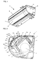
- Figure 1 is a perspective view of an indoor machine of an air conditioner according to the present invention.
- Figure 2 is a sectional view taken along line A-A in Figure 1 .
- Figure 3 is a sectional view showing a state where a guide section is opened in Figure 2 .
- Figure 4 is a sectional view taken along line B-B in Figure 1 .
- Figure 5 is a sectional view showing a state where a guide section is opened in Figure 4 .
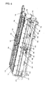
- Figure 6 is a perspective view showing a unit configured by a guide apparatus and a cleaning apparatus.
- Figure 7 is a perspective view of the guide section in the sectional view taken along line A-A in Figure 1 .
- Figure 8 is an enlarged sectional view of the guide section in the sectional view taken along line A-A in Figure 1 .
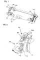
- Figure 9 is a figure showing a state where the guide section in Figure 7 is opened.
- Figure 10 is a figure showing a state where the guide section in Figure 8 is opened.
- Figure 11 is an enlarged perspective view showing a holding mechanism.
- Figure 12 is a figure showing a holding state of the holding mechanism in Figure 11 .
- Figure 13 is a perspective view of a filter.
- Figure 14 is an enlarged view of the main part in Figure 13 .
- Figure 15 is a front view of the filter.
- An air conditioner according to the present invention is configured by an indoor machine 1 and an outdoor machine (not shown).
- the indoor machine 1 includes a casing 4 which houses a heat exchanger 2, an indoor fan 3, and the like.
- the casing 4 includes a front panel 5 whose front opening is supported in an openable and closable manner, a suction port 6 which is formed on the top surface side of the casing 4 and which is formed in a grid shape for sucking the indoor air, and a blow-out port 7 which is formed in a front lower portion of the casing, for blowing out heat-exchanged cool and warm air.
- the whole surface of the blow-out port 7 is covered by an air guide panel 8.
- the size of the air guide panel 8 is set so that the air guide panel 8 covers the blow-out port 7 to reach above the blow-out port 7.
- the air guide panel 8 is configured such that rotary shafts are respectively formed in the upper and lower ends of the air guide panel 8, and that about the rotary shaft at one end side, the other end side of the air guide panel 8 is rotated so that wind is made to blow out in a desired direction.
- the front opening of the casing 4 serves as an opening through which a sheet-like filter 9 is attached into the casing 4.
- the upper portion of the front panel 5 is rotatably fixed to the side surface of the casing 4, so that the front surface of the casing 4 can be opened by pulling up the lower portion of the front panel 5.
- a ventilation path is formed between the suction port 6 and the blow-out port 7.
- the filter 9, the indoor heat exchanger 2, and the blower fan 3 are arranged in this order by taking the suction port 6 side as the upstream side.
- the indoor heat exchanger 2 is formed into a reverse V shape.
- the suction port 6 is formed in substantially the whole surface of the top surface of the casing 4 in the right and left direction.
- the filter 9 is arranged along the inner surface of the suction port 6. Specifically, the filter 9 has a bending property and is configured by a right filter 9b covering the right half of the suction port 6, and a left filter 9a covering the left half of the suction port 6. All the air sucked from the suction port 6 is made to pass through the filter 9, and thereby the contaminant and dust in the air are removed.
- the filters 9a and 9b are supported by guide apparatuses 10, respectively.
- the guide apparatuses 10 are respectively provided on the inner surface side of side walls 17 of the casing 4, and on both side surfaces of a central body 18 which bridges over substantially the center of the casing 4 in the forward and rearward direction. Thereby, the guide apparatuses 10 are configured so as to support the right and left filters 9a and 9b.
- the guide apparatuses 10 not only support the filter 9 in the vicinity of the inner surface of the suction port 6, but also function as a moving path A for moving the filter 9. That is, the guide apparatus 10 is provided along the suction port 6 of the casing 4 (region 10a), and is further extended from the suction port 6 to the front side. Specifically, as shown in Figure 2 and Figure 3 , the guide apparatus 10 is inclined downward on the front side of the region 10a to reach the vicinity of the front panel 5 (region 10b), from where the guide apparatus 10 is folded back in a U-shape to the inside (region 10c), so as to reach the vicinity of the suction port 6 through between the region 10b and the heat exchanger 2 (region 10d).
- the respective regions 10a to 10d are connected by smooth curves.
- the guide apparatus 10 functions as the moving path A along which the filter 9 can be moved.
- the moving path A is provided so as to pass through the cleaning apparatus 12 in the region 10b, where the filter 9 being moved along the moving path A is cleaned.
- the guide apparatus 10 and the cleaning apparatus 12 are configured to be able to be integrally assembled, and thereby are handled as one unit. Therefore, the guide apparatus 10 and the cleaning apparatus 12 are attached into the casing 4 as a unit. Note that Figure 6 shows a state where among left and right guide sections 50 and 50, the left guide section 50 is closed and the right guide section 50 is opened.
- the guide apparatus 10 includes an inner rail 21 which guides the inner peripheral side of the moving path A formed in the U shape, and an outer rail 22 which guides the outer peripheral side of the moving path A.
- the moving path A preferably has such a length that when the filter 9 is moved to the lower side, the upper end of the filter 9 reaches the position from which the upper end of the filter 9 is introduced into the cleaning apparatus 12. With such configuration, it is possible to clean the filter 9 from the lower end to the upper end thereof.
- the guide section 50 for opening and closing the moving path A is provided instead of the inner rail 21 and the outer rail 22.
- the guide section 50 is provided at a position closer to the front side of the casing (closer to the front panel 5) than the cleaning apparatus 12.
- the guide section 50 is provided on each side of the left filter 9a and the right filter 9b.
- the guide section 50 configures a portion of the moving path A in the state where the moving path is closed, and functions as an opening section of the moving path A at the time when the moving path A is opened.
- the guide section 50 is configured by a front face member 52 and a rear face member 53.
- the front face member 52 and the rear face member 53 are formed in a plate shape elongated in the left and right direction of the filter 9 (in the left and right longitudinal direction of the air conditioner).
- the front face member 52 functions as the outer rail 22, and the rear face member 53 functions as the inner rail 21. Therefore, in the front face member 52 and the rear face member 53, the surface for guiding the filter 9 is formed into a curved shape in correspondence with the curved shape in the region 10c.
- Bearings 52a having a C-shaped cross section are provided at the rear end sections (upper end sections seen from the front of the air conditioner) of the longitudinal end sections of the front face member 52.
- the bearing 52a is attached to the guide shaft 54 so as to be rotatable about the guide shaft 54. That is, the lower end (the other end) of the front face member 52 is made rotatable about the upper end side (one end side).
- the guide shaft 54 is fixed to the cleaning apparatus 12. Note that the cleaning apparatus 12 is fixed to the guide apparatus 10 at the both end sections in the left and right longitudinal direction, and thereby the positional relationship between the guide shaft 54 and the guide apparatus 10 is fixed.
- bearings 53a having a substantially C-shaped cross section are similarly provided at the rear end sections (at the upper end sections when seen from the front of the air conditioner) of the longitudinal end sections of the rear face member 53, so that the rear face member 53 is made rotatable about the guide shaft 54. That is, the front face member 52 and the rear face member 53 are configured such that the lower end (the other end) is made rotatable about the same rotation axis at the upper end side (one end side).
- the front face member 52 and the rear face member 53 are made to function as a part of the moving path A in the state where the members are not rotated (in a closed attitude), the front face member 52 and the rear face member 53 are arranged so as to face each other at an interval. Thereby, a gap for guiding the filter 9 is provided between the front face member 52 and the rear face member 53.
- the gap is set substantially equal to a width X of the moving path A except the guide section 50 so that the filter 9 guided by the inner rail 21 and the outer rail 22 can be made to smoothly and continuously pass through the guide section 50.
- the guide section 50 is able to open the moving path A by rotating (by opening rotation of) the front face member 52 and the rear face member 53 so that the other end side (lower end side) of the surface member 52 and the rear face member 53 is directed toward the front of the casing. At this time, the guide section 50 and the region 10b are linearly arranged. Thus, the filter 9 can be easily introduced into and extracted from the moving path A by using the guide section 50 as an inlet/outlet port.
- the lower end section of the front face member 52 is rotated so as to be pulled up, and thereby the rear face member 53 is rotated together with the front face member 52 via a link mechanism 55.
- engagement pins 56 are provided substantially in parallel with the longitudinal direction of the front face member 52.
- receiving plates 57 extended substantially in the perpendicular direction from the rear face member 53 are provided at both the left and right ends of the rear face member 53.
- the engagement hole 58 is configured so as to have a play in the direction of rotation of the engagement pin 56 at the time when the front face member 52 is rotated in the opening direction in the state where the engagement pin 56 is loosely fitted in the engagement hole 58.
- the link mechanism 55 is configured by the engagement pin 56 and the engagement hole 58.
- the engagement pin 56 and the receiving plate 57 are respectively provided on the side close to the guide shaft 54, but the engagement pin 56 and the receiving plate 57 may be provided on the side away from the guide shaft 54. Note that in the configuration in which the engagement pin 56 and the receiving plate 57 are provided on the side close to the guide shaft 54, the height of play necessary for obtaining a predetermined angle ⁇ 1 can be reduced as compared with the case where the engagement pin 56 and the receiving plate 57 are provided on the side away from the guide shaft 54. Therefore, the engagement pin 56 and the receiving plate 57 hardly become an obstacle inside the air conditioner.
- the guide section 50 configured as described above. Now, it is assumed that the guide section 50 is in the closed attitude.
- the filter 9 is taken out from the indoor machine in order to perform cleaning, exchange, or the like, of the filter 9, the front panel 5 is first opened. Then, the front face member 52 is exposed.
- a locking mechanism 59 configured to lock the front face member 52 and the rear face member 53 in the closed attitude.
- the locking mechanism 59 in the present embodiment is configured as a mechanism in which lock and release can be switched by sliding an operation lever in the left and right direction.
- the locking mechanism 59 is not limited to this, and a known mechanism may be adopted as the locking mechanism 59.
- the front face member 52 is made rotatable by releasing the locking mechanism 59.
- the rear face member 53 tends to be rotated (rotated in the closing direction) by the gravity. However, when the front face member 52 continues to be rotated in the opening direction in the state where the engagement pin 56 is brought into contact with the engagement hole 58, the rear face member 53 is also rotated in the opening direction according to the front face member 52.
- the width between the front face member 52 and the rear face member 53 is about the width X on the upper end side (one end side) and is a width X1 (X1 > X) on the lower end side (the other end side).
- the width between the front face member 52 and the rear face member 53 is increased from the upper end side to the lower end side. That is, the inner surface of the guide section 50 can be formed in a tapered shape which is narrowed from the side of the inlet/outlet port 50a to the inside, so that the filter 9 can be easily inserted into the moving path A.
- a holding mechanism 60 for holding the front face member 52 in the opened attitude.
- the holding mechanism 60 includes a holding bar 61 which is formed so as to interfere with the rotational orbit of the front face member 52.
- the base section of the holding bar 61 is fixed to the cleaning apparatus 12.
- the distal end section 61a of the holding bar 61 is formed in a semispherical shape and is bent so as to become substantially perpendicular to a main body section 61b of the holding bar 61. That is, the holding bar 61 is formed such that the axial direction of the distal end section 61a is substantially in parallel with the longitudinal direction of the front face member 52.
- the front face member 52 has an opening 62 formed at the position where the holding bar 61 is brought into contact with the front face member 52.
- the opening 62 is formed so that the main body section 61b of the holding bar 61 is able to pass through the opening 62, but that the distal end section 61a of the holding bar 61 is brought into contact with the opening edge of the opening 62.
- the holding bar 61 is formed so as to be inclined with respect to the front face member 52 in the opened attitude, and is formed so that the distal end section 61a is brought into contact with the edge of the opening 62 just before the front face member 52 reaches the opened attitude.
- the holding mechanism 60 including the holding bar 61 and the opening 62.
- the distal end section 61a of the holding bar 61 is, as shown in Figure 11 , brought into contact with the edge of the opening 62 formed in the front face member 52.
- the holding bar 61 is formed of a synthetic resin and has elasticity. Thus, when an external force is applied to the distal end section 61a, the holding bar 61 is easily deformed and bent.
- the distal end section 61a of the holding bar 61 is left in the state of being hooked by the opening 62 of the front face member 52.
- the front face member 52 holds the opened attitude even when the hand is released from the front face member 52.
- the rear face member 53 is made to be rotated in the closing direction by the gravity.
- the engagement pin 56 is in contact with the engagement hole 58, the rear face member 53 cannot be rotated in the closing direction. In other words, the rear face member 53 is in the state of being held by the link mechanism 55.
- the filter 9 is taken out from the moving path A.
- the holding mechanism 60 also plays a role of stopper which regulates the rotation of the front face member 52.
- the filter 9 is configured to have such a length that the end of the filter 9 is set at substantially the same position as that of the lower end of the guide section 50 in the use state of the air conditioner (in the state where the filter 9 is arranged so as to cover the suction port 6).
- the rear face member 53 is rotated together with the front face member 52, so that the filter 9 is also rotated in the state of being pressed by the rear face member. Therefore, when the guide section 50 is opened, the end of the filter 9 is directed toward the front of the casing 4, so as to be easily taken out.
- the end of the filter 9 (the end on the front panel side) can be moved by the rear face member 53 from the inside place of the air conditioner to the place where the end can be easily taken out. Thereby, the filter 9 can be easily taken out by holding the end of the filter 9.
- the interval between the front face member 52 and the rear face member 53 is set in a funnel-shape (in side view) in which the interval is reduced from the side of the inlet/outlet port 50a to the inside.
- the interval on the side of the inside is set to the width X which is substantially the same as the width of the moving paths A other than the guide section 50, and the interval on the side of the inlet/outlet port 50a is set larger than the width on the side of the inside.
- the filter 9 can be easily inserted into the moving path A from the inlet/outlet port 50a having the width larger than the width of the moving path A.
- the indoor machine of the separate type air conditioner as in the present embodiment is installed at a high position on the wall surface. This often makes it difficult to take out and insert the filter 9.
- the filter 9 is thin and flexible, and hence is easily bent. Thus, when the filter 9 is inserted from the inlet/outlet port 50a by holding the lower portion of the filter 9, the filter 9 is easily bent. This makes it difficult to insert the filter in the case where the width of the inlet/outlet port is substantially the same as the width of the moving path A as in the prior art form.
- the opening width of the inlet/outlet port is made larger than the width X of the moving path A as in the present invention, even when the filter is bent to a certain extent, the filter 9 can be easily inserted into the opening. Further, the opening width is gradually reduced from the opening distal end to the inside. Thus, the filter is inserted into the inside according to such change, so as to reach the moving path.
- the filter 9 can be easily inserted and taken out.
- the surface member 52 is pressed in the closing rotation direction, so that the holding bar 61 is bent to come off from the opening 62. Then, when the surface member 52 continues to be pressed as it is, the guide section 50 is returned to the state of the moving path. Then, the guide section 50 may be locked by the locking mechanism.
- the link mechanism 55 is configured by the engagement pin 56 and the engagement hole 58.
- the link mechanism 55 may also be configured in such a manner that a projecting section is provided in the receiving plate 57 instead of the engagement hole 58, and that the projecting section is brought into contact with the engagement pin 56.
- the front face member and the rear face member can be brought into contact with each other at the predetermined angle ⁇ 1.
- the link mechanism may also be configured in such a manner that a projecting section is provided only in the receiving plate 57, and that the projection section is brought into contact with the front face side of the front face member 52 in the state where the surface member and the rear face member are set to form the predetermined angle ⁇ 1.
- the holding mechanism 60 for holding the front face member is described, but a holding mechanism for holding the rear face member may also be provided at the same time. Further, in the present embodiment, the holding mechanism 60 for holding the front face member is used, but the holding mechanism 60 for holding the front face member may not be used. In this case, the front face member is not held, but instead of the holding mechanism 60, a holding mechanism for holding the rear face member is provided.
- the front face member When the guide is in the opened state, the front face member is made to be rotated in the closing direction by the gravity, so that the interval between the front face member and the rear face member of the guide section 50 becomes the same as the width in the state of the moving path.
- the filter when the filter is inserted so as to be brought into contact with the front face member, the front face member is rotated by the filter in the opening direction because the front face member is rotatable in the opening direction. As a result, the interval between the front face member and the rear face member is increased. Therefore, even in such configuration, the filter can be easily inserted.
- the front face member and the rear face member which configure the above described guide section are freely rotated about the same rotation shaft 54 provided on the side of the outer rail 22, but the rotation shaft may be separately provided for each of the front face member and the rear face member.
- the rotation shaft may be separately provided for each of the front face member and the rear face member.
- it is configured such that the front face member is rotated about the rotation shaft provided on the side of the outer rail 22, and that the rear face member is rotated about the rotation shaft provided on the side of the inner rail 21.
- the filter 9 is configured by a filter net 13 and a filter frame 14 for supporting the four sides of the filter net 13.
- the filter frame 14 is configured by a vertical frame 14a for supporting the left and right sides, and a lateral frame 14b for supporting the upper and lower sides.
- the vertical frame 14a is formed in a corrugated shape in side view.
- recessions and projections are formed in the vertical direction (moving direction) on the inner surface side of the vertical frame 14a.
- a gear 32 rotated by a motor 30 is provided on the inner side of the rear face member 53. Both the left and right end sections of the rear face member are cut out so as to expose the gear 32 in the moving path A (see Figure 6 ) from the cut out sections.
- the recessions and projections of the vertical frame 14a are configured to mesh with the gear 32. Thereby, the filter 9 can be moved forward and rearward by the rotation of the gear 32. Further, the filter 9 can be easily bent in the vertical direction by forming the recessions and projections into the corrugated shape. Thereby, the filter 9 can be easily folded back in the U-shape.
- the recessed and projected surface formed on the inner surface side of the vertical frame 14a may only have a shape which can be meshed with the teeth of the driven gear 32. However, it is preferred that the pitch of the recessions and projections is set to be equal to the pitch of the teeth of the driven gear 32. Thus, the tooth skip can be more effectively prevented.
- a rib 15 is provided so that the inside of the filter frame 14 is divided in a grid shape.
- the rib 15 is fixed to the filter net 13 so as to support the filter net 13. Thereby, the bending and waving of the filter 9 can be prevented.
- the rib 15 is configured by a vertical rib 15a arranged in the vertical direction and a lateral rib 15b arranged in the lateral direction.
- the vertical rib 15a is formed to have a small thickness, and the lateral rib 15b has a thickness larger than the thickness of the vertical rib 15a.
- a slit 16 is provided between the lateral rib 15b and the vertical frame 14a of the filter frame 14, so that the lateral rib 15 and the vertical frame 14a are discontinuous from each other.
- the vertical frame 14a and the lateral rib 15b are configured to be discontinuous from each other, the vertical frame 14a is hardly influenced by the lateral rib 15b, so that the bending property of the filter 9 in the vertical direction can be held.
- any material only having flexibility can be used as the material of the filter frame 14, and hence any of polypropylene (PP), polyethylene terephthalate (PET), synthetic resin such as soft resin, rubber and paper may be used.
- the filter net 13 for passing the air sucked from the suction port 6 is stretched in the upper portion of the filter 9.
- a thin resin sheet 13a is stretched in the lower portion of the filter 9 instead of the filter net 13, so that the lower portion of the filter 9 is configured to prevent the passage of the air.
- the resin sheet 13a is formed to have a small thickness similarly to the vertical rib 15a. Thereby, the bending property in the vertical direction is secured for the filter 9 as a whole.
- the filter net 13 may be stretched on the whole surface of the filter 9.
- the cleaning apparatus 12 is provided in the region 10b of the guide apparatus 10. Since the region 10b is formed in the linear shape, the filter 9 can be easily attached to the cleaning apparatus 12. Further, since the cleaning apparatus 12 is provided on the front side of the casing 4, the filter 9 can be easily attached to the cleaning apparatus 12.
- the cleaning apparatus 12 is configured by an upper case 37 and a lower case 38 which have a substantially U-shaped cross section, and is fixed to the casing 4 so as to laterally bridge the front of the casing 4 in the state where the recessed sections of the upper case 37 and the lower case 38 are set to face each other.
- a gap is between the upper case 37 and the lower case 38, so that the filter 9 can be moved through the gap.
- a very narrow interval is maintained between the upper case 37 and the surface of the filter 9 and between the lower case 38 and the surface of the filter 9.
- the left and right ends of a suction section 34 are opened. That is, it is configured such that the filter 9 can be made to pass through the cleaning apparatus 12 formed in the box shape as a whole.
- the suction apparatus 35 is configured by a suction fan, and is connected to a duct (not shown) communicating the outside. A suction force is generated by rotating the suction fan, so that dust in the filter 9 can be sucked by the cleaning apparatus 12. The sucked air is exhausted to the outside from the duct.
- the interval between the upper case 37 and the lower case 38 is set to be substantially equal to the width of the lateral ribs 15b of the filter 9.
- the filter 9 when the filter 9 is cleaned, the filter 9 is moved forward by the rotation of the gear 32. At this time, the moving path A is formed by the guide apparatus 10 so as to be folded back into the U-shape in the front portion of the casing 4. Thereby, the front end of the filter 9 is guided backward (on the downstream side) while the filter 9 is bent according to the forward movement. As a result, the whole surface of the filter 9 can be cleaned.
- the present invention can be effectively used for an air conditioner which is capable of blowing off conditioned air at the time of cooling and warming operation.
Landscapes
- Engineering & Computer Science (AREA)
- Chemical & Material Sciences (AREA)
- Combustion & Propulsion (AREA)
- Mechanical Engineering (AREA)
- General Engineering & Computer Science (AREA)
- Air Filters, Heat-Exchange Apparatuses, And Housings Of Air-Conditioning Units (AREA)
Abstract
Description
- The present invention relates to an air conditioner capable of cleaning a filter.
- In an air conditioner, a filter is provided along the inner surface side of a suction port of a casing of an indoor machine. The filter is able to remove dust in the air sucked from the suction port, and thereby able to prevent the dust from entering into the casing. When the filter is soiled, the air-conditioning capacity of the air conditioner is decreased due to clogging of the filter, and hence it is necessary to clean the filter.
- Thus, there is an air conditioner which is capable of automatically cleaning the filter. For example, there is disclosed in
patent document 1 an air conditioning apparatus (air conditioner) which includes a plate-shaped filter arranged along the inner surface side of a suction port of a casing, a cleaning apparatus configured to clean the filter, and a moving path for moving the filter with respect to the cleaning apparatus, and in which a guide piece configuring a portion of the moving path is provided so that the moving path is opened to the outside of the casing by rotating the other end of the guide piece about a rotating section provided at one end side of the guide piece. - Thereby, when the filter is reciprocated, the whole surface of the filter can be automatically cleaned by the filter cleaning apparatus. Also, the guide piece is opened to the outside of the casing, so that when the filter is again attached after being removed, the filter can be easily inserted into the moving path. Then, when the filter is reciprocated, the whole surface of the filter can be automatically cleaned by the filter cleaning apparatus.
- Patent document 1: Japanese Patent Laid-Open Publication No.
2007-147122 - However, in the air conditioner as disclosed in
patent document 1, the guide piece is configured to be opened to the outside of the casing, but an inner guide and an outer guide, which configure the guide piece, are integrally formed. Thus, the size of the opening section of the guide piece is substantially the same as the width of the moving path of the filter. As a result, the width of the opening section is not enough to insert the filter, and hence it takes time and labor to insert the filter. - In view of the above described problem, it is an object of the present invention to provide an air conditioner in which the filter can be easily inserted in the opening section.
- In order to achieve the above described object, according to the present invention, there is provided an air conditioner which includes: a filter arranged along the inner surface side of a suction port of a casing; a cleaning apparatus configured to clean the filter; a moving path for moving the filter with respect to the cleaning apparatus; and a guide section configuring a portion of the moving path, and which opens the moving path to the outside of the casing by rotating the other end of the guide section about one end side of the guide section, the air conditioner being featured in that the guide section is configured by a front face member arranged on the front face side of the filter, and a rear face member arranged on the rear face side of the filter.
- According to the above described configuration, the guide section is provided so as to be separated into the front face member and the rear face member. Thus, it is possible to open the moving path to the outside of the casing by respectively rotating the front face member and the rear face member. Further, when the filter is inserted, and when the filter abuts on the surface member, the front face member is rotated in the opening direction to enlarge the opening section. Thereby, the filter can be easily inserted.
- Further, in the air conditioner according to the present invention, the width between the front face member and the rear face member is preferably increased from the one end side to the other end side of the guide section in the state where the moving path is opened.
- That is, the width of the moving path is set to have substantially the same width as a whole in the state where the moving path is closed, and the front face member and the rear face member are arranged so as to face each other at an interval. Then, when the front face member and the rear face member is respectively rotated in the direction to open the moving path, the width (the width between the front face member and the rear face member) of the guide section which is to serve as the opening section of the moving path, can be increased from the one end side to the other end side of the guide section.
- In other words, the inner surface of the guide section (opening section) can be formed in a tapered shape whose width is reduced from the inlet/outlet port side to the inside. Thereby, the filter can be easily inserted into the moving path.
- Further, the air conditioner according to the present invention is preferably configured such that the rear face member is rotated via a link mechanism by rotating the front face member. In such configuration, the rear face member can also be rotated by the rotation of the front face member, and thereby the operability can be improved.
- Further, in the air conditioner according to the present invention, the link mechanism is preferably configured such that after the front face member is rotated by a predetermined angle, the rear face member is rotated according to the rotation of the front face member.
- In the above described configuration, the rear face member is not rotated until the front face member is rotated by the predetermined angle. Therefore, it is possible to configure such that the width between the front face member and the rear face member is increased from one end side to the other end side of the guide section only by rotating the front face member.
- Further, by rotating the surface member together with the rear face member in such state, the guide section can be directed toward the outside of the casing, so that the filter can be smoothly introduced into the moving path.
- Further, when the guide section is made to function as the moving path, the front face member may only be rotated in the reverse direction. Thereby, it is possible to reduce the width between the front face member and the rear face member, so as to return the surface member and the rear face member to the original state (the state where the interval between the front face member and the rear face member is substantially fixed) .
- The air conditioner according to the present invention is preferably provided with a holding mechanism configured to make the front face member, which is rotated by the predetermined angle together with the rear face member, held in the state rotated by the predetermined angle. In such configuration, when the filter is inserted, the width of the guide section, which serves as the opening section of the moving path, can be held sufficiently wide, and hence the filter can be easily inserted.
- Further, the air conditioner according to the present invention may also be configured such that in the state where the front face member is fixed and held by the holding mechanism, the rear face member is held by the link mechanism so as to be inclined at a fixed angle with respect to the front face member.
- In such configuration, the angle formed between the front face member and the rear face member can be held at the predetermined angle only by the holding mechanism configured to hold only the front face member, and the rear face member is held by the link mechanism. Thus, the holding mechanism for holding the rear face member need not be separately provided.
- Further, in the air conditioner according to the present invention, the holding mechanism may also be configured so as to regulate the rotation of the front face member.
- In such configuration, it is possible to prevent the front face member from being excessively rotated. Further, a rotation regulation member need not be separately provided.
- Note that it may also be configured such that the front face member and the rear face member, which configure the guide section, are freely rotated about the same rotation axis.
- In the air conditioner according to the present invention, a portion of the moving path for moving the filter is configured by the guide section formed by the front face member and the rear face member, and also the other end of the guide section is rotated in the opening direction about one end of the guide section so that the moving path is opened toward the outside of the casing. Thereby, the filter can be easily inserted into the moving path.
-
-
Figure 1 is a perspective view of an indoor machine of an air conditioner according to the present invention; -
Figure 2 is a sectional view taken along line A-A inFigure 1 ; -
Figure 3 is a sectional view showing a state where a guide section is opened inFigure 2 ; -
Figure 4 is a sectional view taken along line B-B inFigure 1 ; -
Figure 5 is a sectional view showing a state where a guide section is opened inFigure 4 ; -
Figure 6 is a perspective view showing a unit configured by a guide apparatus and a cleaning apparatus; -
Figure 7 is a perspective view of the guide section in the sectional view taken along line A-A inFigure 1 ; -
Figure 8 is an enlarged sectional view of the guide section in the sectional view taken along line A-A inFigure 1 ; -
Figure 9 is a figure showing a state where the guide section inFigure 7 is opened; -
Figure 10 is a figure showing a state where the guide section inFigure 8 is opened; -
Figure 11 is an enlarged perspective view showing a holding mechanism; -
Figure 12 is a figure showing a holding state of the holding mechanism inFigure 11 ; -
Figure 13 is a perspective view of a filter; -
Figure 14 is an enlarged view of the main part inFigure 13 ; and -
Figure 15 is a front view of the filter. -
- A
- Moving path
- 1
- Indoor machine
- 2
- Heat exchanger
- 3
- Indoor fan
- 4
- Casing
- 5
- Front panel
- 6
- Suction port
- 7
- Blow-out port
- 8
- Air guide panel
- 9
- Filter
- 10
- Guide apparatus
- 12
- Cleaning apparatus
- 13
- Filter net
- 13a
- Resin sheet
- 14
- Filter frame
- 14a
- Vertical frame
- 14b
- Lateral frame
- 14c
- Projecting section
- 14d
- Groove section
- 15
- Rib
- 15a
- Vertical rib
- 15b
- Lateral rib
- 17
- Side wall
- 18
- Central body
- 19
- Guide section
- 20
- Stopper
- 21
- Inner rail
- 22
- Outer rail
- 30
- Motor
- 32
- Driven gear
- 35
- Suction apparatus
- 37
- Upper case
- 38
- Lower case
- 50
- Guide section
- 52
- Front face member
- 53
- Rear face member
- 54
- Guide shaft
- 55
- Link mechanism
- 56
- Engagement pin
- 57
- Receiving plate
- 58
- Engagement hole
- 59
- Locking mechanism
- 60
- Holding mechanism
- 61
- Holding bar
- 62
- Opening
- In the following, an embodiment according to the present invention will be described with reference to the accompanying drawings.
Figure 1 is a perspective view of an indoor machine of an air conditioner according to the present invention.Figure 2 is a sectional view taken along line A-A inFigure 1 .Figure 3 is a sectional view showing a state where a guide section is opened inFigure 2 .Figure 4 is a sectional view taken along line B-B inFigure 1 .Figure 5 is a sectional view showing a state where a guide section is opened inFigure 4 .Figure 6 is a perspective view showing a unit configured by a guide apparatus and a cleaning apparatus.Figure 7 is a perspective view of the guide section in the sectional view taken along line A-A inFigure 1 .Figure 8 is an enlarged sectional view of the guide section in the sectional view taken along line A-A inFigure 1 .Figure 9 is a figure showing a state where the guide section inFigure 7 is opened.Figure 10 is a figure showing a state where the guide section inFigure 8 is opened.Figure 11 is an enlarged perspective view showing a holding mechanism.Figure 12 is a figure showing a holding state of the holding mechanism inFigure 11 .Figure 13 is a perspective view of a filter.Figure 14 is an enlarged view of the main part inFigure 13 .Figure 15 is a front view of the filter. - An air conditioner according to the present invention is configured by an
indoor machine 1 and an outdoor machine (not shown). Theindoor machine 1 includes acasing 4 which houses aheat exchanger 2, anindoor fan 3, and the like. As shown inFigure 1 to Figure 6 , thecasing 4 includes afront panel 5 whose front opening is supported in an openable and closable manner, asuction port 6 which is formed on the top surface side of thecasing 4 and which is formed in a grid shape for sucking the indoor air, and a blow-outport 7 which is formed in a front lower portion of the casing, for blowing out heat-exchanged cool and warm air. - The whole surface of the blow-out
port 7 is covered by anair guide panel 8. The size of theair guide panel 8 is set so that theair guide panel 8 covers the blow-outport 7 to reach above the blow-outport 7. Theair guide panel 8 is configured such that rotary shafts are respectively formed in the upper and lower ends of theair guide panel 8, and that about the rotary shaft at one end side, the other end side of theair guide panel 8 is rotated so that wind is made to blow out in a desired direction. - The front opening of the
casing 4 serves as an opening through which a sheet-like filter 9 is attached into thecasing 4. The upper portion of thefront panel 5 is rotatably fixed to the side surface of thecasing 4, so that the front surface of thecasing 4 can be opened by pulling up the lower portion of thefront panel 5. - As shown in
Figure 2 , in thecasing 4, a ventilation path is formed between thesuction port 6 and the blow-outport 7. In the ventilation path, thefilter 9, theindoor heat exchanger 2, and theblower fan 3 are arranged in this order by taking thesuction port 6 side as the upstream side. Theindoor heat exchanger 2 is formed into a reverse V shape. In thecasing 4, there is also provided acleaning apparatus 12 for cleaning thefilter 9. - The
suction port 6 is formed in substantially the whole surface of the top surface of thecasing 4 in the right and left direction. Thefilter 9 is arranged along the inner surface of thesuction port 6. Specifically, thefilter 9 has a bending property and is configured by aright filter 9b covering the right half of thesuction port 6, and aleft filter 9a covering the left half of thesuction port 6. All the air sucked from thesuction port 6 is made to pass through thefilter 9, and thereby the contaminant and dust in the air are removed. - The
filters guide apparatuses 10, respectively. The guide apparatuses 10 are respectively provided on the inner surface side ofside walls 17 of thecasing 4, and on both side surfaces of acentral body 18 which bridges over substantially the center of thecasing 4 in the forward and rearward direction. Thereby, theguide apparatuses 10 are configured so as to support the right and leftfilters - The guide apparatuses 10 not only support the
filter 9 in the vicinity of the inner surface of thesuction port 6, but also function as a moving path A for moving thefilter 9. That is, theguide apparatus 10 is provided along thesuction port 6 of the casing 4 (region 10a), and is further extended from thesuction port 6 to the front side. Specifically, as shown inFigure 2 andFigure 3 , theguide apparatus 10 is inclined downward on the front side of theregion 10a to reach the vicinity of the front panel 5 (region 10b), from where theguide apparatus 10 is folded back in a U-shape to the inside (region 10c), so as to reach the vicinity of thesuction port 6 through between theregion 10b and the heat exchanger 2 (region 10d). Therespective regions 10a to 10d are connected by smooth curves. - In this way, the
guide apparatus 10 functions as the moving path A along which thefilter 9 can be moved. The moving path A is provided so as to pass through thecleaning apparatus 12 in theregion 10b, where thefilter 9 being moved along the moving path A is cleaned. As shown inFigure 6 , theguide apparatus 10 and thecleaning apparatus 12 are configured to be able to be integrally assembled, and thereby are handled as one unit. Therefore, theguide apparatus 10 and thecleaning apparatus 12 are attached into thecasing 4 as a unit. Note thatFigure 6 shows a state where among left andright guide sections left guide section 50 is closed and theright guide section 50 is opened. - The
guide apparatus 10 includes aninner rail 21 which guides the inner peripheral side of the moving path A formed in the U shape, and anouter rail 22 which guides the outer peripheral side of the moving path A. When both the left and right end sections of thefilter 9 are held between theinner rail 21 and theouter rail 22 of theguide apparatus 10, which are configured in this way, thefilter 9 can be guided so as to be moved substantially in the U shape. - The moving path A preferably has such a length that when the
filter 9 is moved to the lower side, the upper end of thefilter 9 reaches the position from which the upper end of thefilter 9 is introduced into thecleaning apparatus 12. With such configuration, it is possible to clean thefilter 9 from the lower end to the upper end thereof. - Further, in a portion of the
region 10c, which ranges from near the boundary between theregion 10b and theregion 10c, to the position closest to thefront panel 5, theguide section 50 for opening and closing the moving path A is provided instead of theinner rail 21 and theouter rail 22. Theguide section 50 is provided at a position closer to the front side of the casing (closer to the front panel 5) than thecleaning apparatus 12. - The
guide section 50 is provided on each side of theleft filter 9a and theright filter 9b. Theguide section 50 configures a portion of the moving path A in the state where the moving path is closed, and functions as an opening section of the moving path A at the time when the moving path A is opened. - The
guide section 50 is configured by afront face member 52 and arear face member 53. Thefront face member 52 and therear face member 53 are formed in a plate shape elongated in the left and right direction of the filter 9 (in the left and right longitudinal direction of the air conditioner). In the state where the moving path A is closed, thefront face member 52 functions as theouter rail 22, and therear face member 53 functions as theinner rail 21. Therefore, in thefront face member 52 and therear face member 53, the surface for guiding thefilter 9 is formed into a curved shape in correspondence with the curved shape in theregion 10c. -
Bearings 52a having a C-shaped cross section are provided at the rear end sections (upper end sections seen from the front of the air conditioner) of the longitudinal end sections of thefront face member 52.
On the front side of thecleaning apparatus 12, there is provided aguide shaft 54 whose axial direction is in parallel with the left and right longitudinal direction of the air conditioner. Thebearing 52a is attached to theguide shaft 54 so as to be rotatable about theguide shaft 54. That is, the lower end (the other end) of thefront face member 52 is made rotatable about the upper end side (one end side). - The
guide shaft 54 is fixed to thecleaning apparatus 12. Note that thecleaning apparatus 12 is fixed to theguide apparatus 10 at the both end sections in the left and right longitudinal direction, and thereby the positional relationship between theguide shaft 54 and theguide apparatus 10 is fixed. - Further,
bearings 53a having a substantially C-shaped cross section are similarly provided at the rear end sections (at the upper end sections when seen from the front of the air conditioner) of the longitudinal end sections of therear face member 53, so that therear face member 53 is made rotatable about theguide shaft 54. That is, thefront face member 52 and therear face member 53 are configured such that the lower end (the other end) is made rotatable about the same rotation axis at the upper end side (one end side). - When the
front face member 52 and therear face member 53 are made to function as a part of the moving path A in the state where the members are not rotated (in a closed attitude), thefront face member 52 and therear face member 53 are arranged so as to face each other at an interval. Thereby, a gap for guiding thefilter 9 is provided between thefront face member 52 and therear face member 53. The gap is set substantially equal to a width X of the moving path A except theguide section 50 so that thefilter 9 guided by theinner rail 21 and theouter rail 22 can be made to smoothly and continuously pass through theguide section 50. - The
guide section 50 is able to open the moving path A by rotating (by opening rotation of) thefront face member 52 and therear face member 53 so that the other end side (lower end side) of thesurface member 52 and therear face member 53 is directed toward the front of the casing. At this time, theguide section 50 and theregion 10b are linearly arranged. Thus, thefilter 9 can be easily introduced into and extracted from the moving path A by using theguide section 50 as an inlet/outlet port. - In order to actually rotate the
guide section 50 in the opening direction, the lower end section of thefront face member 52 is rotated so as to be pulled up, and thereby therear face member 53 is rotated together with thefront face member 52 via alink mechanism 55. - The
link mechanism 55 will be described. At both the left and right ends of thefront face member 52, engagement pins 56 are provided substantially in parallel with the longitudinal direction of thefront face member 52. Further, receivingplates 57 extended substantially in the perpendicular direction from therear face member 53 are provided at both the left and right ends of therear face member 53. In the receivingplate 57, there is provided a long hole-shapedengagement hole 58, into which theengagement pin 56 of the front face member is made to loosely fit. Theengagement hole 58 is configured so as to have a play in the direction of rotation of theengagement pin 56 at the time when thefront face member 52 is rotated in the opening direction in the state where theengagement pin 56 is loosely fitted in theengagement hole 58. Thelink mechanism 55 is configured by theengagement pin 56 and theengagement hole 58. - Note that although the
engagement pin 56 and the receivingplate 57 are respectively provided on the side close to theguide shaft 54, but theengagement pin 56 and the receivingplate 57 may be provided on the side away from theguide shaft 54. Note that in the configuration in which theengagement pin 56 and the receivingplate 57 are provided on the side close to theguide shaft 54, the height of play necessary for obtaining a predetermined angle θ1 can be reduced as compared with the case where theengagement pin 56 and the receivingplate 57 are provided on the side away from theguide shaft 54. Therefore, theengagement pin 56 and the receivingplate 57 hardly become an obstacle inside the air conditioner. - There will be described the operation of the
guide section 50 configured as described above. Now, it is assumed that theguide section 50 is in the closed attitude. When thefilter 9 is taken out from the indoor machine in order to perform cleaning, exchange, or the like, of thefilter 9, thefront panel 5 is first opened. Then, thefront face member 52 is exposed. In thesurface member 52, there is provided alocking mechanism 59 configured to lock thefront face member 52 and therear face member 53 in the closed attitude. - As shown in
Figure 6 , thelocking mechanism 59 in the present embodiment is configured as a mechanism in which lock and release can be switched by sliding an operation lever in the left and right direction. However, thelocking mechanism 59 is not limited to this, and a known mechanism may be adopted as thelocking mechanism 59. Thefront face member 52 is made rotatable by releasing thelocking mechanism 59. - As shown in
Figure 8 , when thefront face member 52 which is made rotatable is rotated in the opening direction (rotated clockwise in the figure), theengagement pin 56 is also rotated. Theengagement pin 56 is brought into contact with theengagement hole 58 at an intermediate position M at which the angle formed between thefront face member 52 and therear face member 53 becomes the predetermined angle θ1. - The
rear face member 53 tends to be rotated (rotated in the closing direction) by the gravity. However, when thefront face member 52 continues to be rotated in the opening direction in the state where theengagement pin 56 is brought into contact with theengagement hole 58, therear face member 53 is also rotated in the opening direction according to thefront face member 52. - That is, as shown in
Figure 10 , when thefront face member 52 is further rotated from the intermediate position M, therear face member 53 is simultaneously rotated in the opening direction in the state where theengagement pin 56 is brought into contact with theengagement hole 58, in other words, in the state where the predetermined angle θ1 is maintained. Then, when thefront face member 52 is further rotated by a predetermined angle θ2 from the intermediate position M, thefront face member 52 and therear face member 53 are set in an opened attitude. - In the present embodiment, when the
front face member 52 is rotated simultaneously with therear face member 53, thefront face member 52 and therear face member 53 are rotated about the same axis (guide shaft 54). Thus, the relative positional relationship between thefront face member 52 and therear face member 53 is not changed, so that the link mechanism can be simply configured. - As described above, in the opened attitude of the
guide section 50, the width between thefront face member 52 and therear face member 53 is about the width X on the upper end side (one end side) and is a width X1 (X1 > X) on the lower end side (the other end side). Thus, the width between thefront face member 52 and therear face member 53 is increased from the upper end side to the lower end side. That is, the inner surface of theguide section 50 can be formed in a tapered shape which is narrowed from the side of the inlet/outlet port 50a to the inside, so that thefilter 9 can be easily inserted into the moving path A. - In the present embodiment, there is provided a
holding mechanism 60 for holding thefront face member 52 in the opened attitude. The holdingmechanism 60 includes a holdingbar 61 which is formed so as to interfere with the rotational orbit of thefront face member 52. The base section of the holdingbar 61 is fixed to thecleaning apparatus 12. Thedistal end section 61a of the holdingbar 61 is formed in a semispherical shape and is bent so as to become substantially perpendicular to amain body section 61b of the holdingbar 61. That is, the holdingbar 61 is formed such that the axial direction of thedistal end section 61a is substantially in parallel with the longitudinal direction of thefront face member 52. - On the other hand, the
front face member 52 has anopening 62 formed at the position where the holdingbar 61 is brought into contact with thefront face member 52. Theopening 62 is formed so that themain body section 61b of the holdingbar 61 is able to pass through theopening 62, but that thedistal end section 61a of the holdingbar 61 is brought into contact with the opening edge of theopening 62. Further, the holdingbar 61 is formed so as to be inclined with respect to thefront face member 52 in the opened attitude, and is formed so that thedistal end section 61a is brought into contact with the edge of theopening 62 just before thefront face member 52 reaches the opened attitude. - There will be described the operation of the
holding mechanism 60 including the holdingbar 61 and theopening 62. When theguide section 50 is rotated in the opening direction and when thefront face member 52 approaches the opened attitude, thedistal end section 61a of the holdingbar 61 is, as shown inFigure 11 , brought into contact with the edge of theopening 62 formed in thefront face member 52. The holdingbar 61 is formed of a synthetic resin and has elasticity. Thus, when an external force is applied to thedistal end section 61a, the holdingbar 61 is easily deformed and bent. - Thus, when the
front face member 52 continues to be rotated as it is in the state where thedistal end section 61a is brought into contact with the opening edge, thedistal end section 61a is bent backward while riding onto the edge of theopening 62. Thedistal end section 61a is quickly returned to the original state at the time when riding across theopening 62, so that theguide section 50 is held in this attitude by the holding bar 61 (Figure 12 ). - Thereby, the
distal end section 61a of the holdingbar 61 is left in the state of being hooked by theopening 62 of thefront face member 52. Thus, thefront face member 52 holds the opened attitude even when the hand is released from thefront face member 52. At this time, therear face member 53 is made to be rotated in the closing direction by the gravity. However, since theengagement pin 56 is in contact with theengagement hole 58, therear face member 53 cannot be rotated in the closing direction. In other words, therear face member 53 is in the state of being held by thelink mechanism 55. - Then, when the
front face member 52 is held by the holdingmechanism 60, the angle formed between thefront face member 52 and therear face member 53 can be kept at the predetermined angle θ1. In this holding state, thefilter 9 is taken out from the moving path A. - Note that when the
front face member 52 in the opened attitude is forced to be further rotated in the opening direction, the rotation of thefront face member 52 is regulated because the edge of theopening 62 on the side closest to thebearing 52a is brought into contact with the holdingbar 61. That is, the holdingmechanism 60 also plays a role of stopper which regulates the rotation of thefront face member 52. - The
filter 9 is configured to have such a length that the end of thefilter 9 is set at substantially the same position as that of the lower end of theguide section 50 in the use state of the air conditioner (in the state where thefilter 9 is arranged so as to cover the suction port 6). In the opened attitude of theguide section 50, as shown inFigure 3 andFigure 5 , therear face member 53 is rotated together with thefront face member 52, so that thefilter 9 is also rotated in the state of being pressed by the rear face member. Therefore, when theguide section 50 is opened, the end of thefilter 9 is directed toward the front of thecasing 4, so as to be easily taken out. - In this way, the end of the filter 9 (the end on the front panel side) can be moved by the
rear face member 53 from the inside place of the air conditioner to the place where the end can be easily taken out. Thereby, thefilter 9 can be easily taken out by holding the end of thefilter 9. - In the state where the
front face member 52 is held by the holdingmechanism 60, the interval between thefront face member 52 and therear face member 53 is set in a funnel-shape (in side view) in which the interval is reduced from the side of the inlet/outlet port 50a to the inside. The interval on the side of the inside is set to the width X which is substantially the same as the width of the moving paths A other than theguide section 50, and the interval on the side of the inlet/outlet port 50a is set larger than the width on the side of the inside. - Therefore, the
filter 9 can be easily inserted into the moving path A from the inlet/outlet port 50a having the width larger than the width of the moving path A. In many cases, the indoor machine of the separate type air conditioner as in the present embodiment is installed at a high position on the wall surface. This often makes it difficult to take out and insert thefilter 9. - The
filter 9 is thin and flexible, and hence is easily bent. Thus, when thefilter 9 is inserted from the inlet/outlet port 50a by holding the lower portion of thefilter 9, thefilter 9 is easily bent. This makes it difficult to insert the filter in the case where the width of the inlet/outlet port is substantially the same as the width of the moving path A as in the prior art form. - However, in the case where the opening width of the inlet/outlet port is made larger than the width X of the moving path A as in the present invention, even when the filter is bent to a certain extent, the
filter 9 can be easily inserted into the opening. Further, the opening width is gradually reduced from the opening distal end to the inside. Thus, the filter is inserted into the inside according to such change, so as to reach the moving path. - In this way, the
filter 9 can be easily inserted and taken out. Note that when theguide section 50 is to be returned to the state of the moving path, thesurface member 52 is pressed in the closing rotation direction, so that the holdingbar 61 is bent to come off from theopening 62. Then, when thesurface member 52 continues to be pressed as it is, theguide section 50 is returned to the state of the moving path. Then, theguide section 50 may be locked by the locking mechanism. - Note that in the present embodiment, the
link mechanism 55 is configured by theengagement pin 56 and theengagement hole 58. However, thelink mechanism 55 may also be configured in such a manner that a projecting section is provided in the receivingplate 57 instead of theengagement hole 58, and that the projecting section is brought into contact with theengagement pin 56. In this case, when the lower surface of the projecting section is located at the position where theengagement hole 58 is brought into contact with theengagement pin 56, the front face member and the rear face member can be brought into contact with each other at the predetermined angle θ1. - Alternatively, the link mechanism may also be configured in such a manner that a projecting section is provided only in the receiving
plate 57, and that the projection section is brought into contact with the front face side of thefront face member 52 in the state where the surface member and the rear face member are set to form the predetermined angle θ1. - In the present embodiment, only the
holding mechanism 60 for holding the front face member is described, but a holding mechanism for holding the rear face member may also be provided at the same time. Further, in the present embodiment, the holdingmechanism 60 for holding the front face member is used, but theholding mechanism 60 for holding the front face member may not be used. In this case, the front face member is not held, but instead of theholding mechanism 60, a holding mechanism for holding the rear face member is provided. - When the guide is in the opened state, the front face member is made to be rotated in the closing direction by the gravity, so that the interval between the front face member and the rear face member of the
guide section 50 becomes the same as the width in the state of the moving path. At this time, when the filter is inserted so as to be brought into contact with the front face member, the front face member is rotated by the filter in the opening direction because the front face member is rotatable in the opening direction. As a result, the interval between the front face member and the rear face member is increased. Therefore, even in such configuration, the filter can be easily inserted. - Note that in the present embodiment, the front face member and the rear face member which configure the above described guide section are freely rotated about the
same rotation shaft 54 provided on the side of theouter rail 22, but the rotation shaft may be separately provided for each of the front face member and the rear face member. For example, it is configured such that the front face member is rotated about the rotation shaft provided on the side of theouter rail 22, and that the rear face member is rotated about the rotation shaft provided on the side of theinner rail 21. - As shown in
Figure 13 andFigure 15 , thefilter 9 is configured by afilter net 13 and afilter frame 14 for supporting the four sides of thefilter net 13. Thefilter frame 14 is configured by avertical frame 14a for supporting the left and right sides, and alateral frame 14b for supporting the upper and lower sides. - As shown in
Figure 14 , thevertical frame 14a is formed in a corrugated shape in side view. When thevertical frame 14a is formed in the corrugated shape, recessions and projections are formed in the vertical direction (moving direction) on the inner surface side of thevertical frame 14a. On the other hand, in theregion 10c, agear 32 rotated by amotor 30 is provided on the inner side of therear face member 53. Both the left and right end sections of the rear face member are cut out so as to expose thegear 32 in the moving path A (seeFigure 6 ) from the cut out sections. - Also, the recessions and projections of the
vertical frame 14a are configured to mesh with thegear 32. Thereby, thefilter 9 can be moved forward and rearward by the rotation of thegear 32. Further, thefilter 9 can be easily bent in the vertical direction by forming the recessions and projections into the corrugated shape. Thereby, thefilter 9 can be easily folded back in the U-shape. - The recessed and projected surface formed on the inner surface side of the
vertical frame 14a may only have a shape which can be meshed with the teeth of the drivengear 32. However, it is preferred that the pitch of the recessions and projections is set to be equal to the pitch of the teeth of the drivengear 32. Thus, the tooth skip can be more effectively prevented. - Further, a rib 15 is provided so that the inside of the
filter frame 14 is divided in a grid shape. The rib 15 is fixed to the filter net 13 so as to support thefilter net 13. Thereby, the bending and waving of thefilter 9 can be prevented. The rib 15 is configured by avertical rib 15a arranged in the vertical direction and alateral rib 15b arranged in the lateral direction. Thevertical rib 15a is formed to have a small thickness, and thelateral rib 15b has a thickness larger than the thickness of thevertical rib 15a. By being configured in this way, thefilter 9 can be easily bent in the vertical direction while maintaining the lateral rigidity. - Further, as shown in
Figure 14 , aslit 16 is provided between thelateral rib 15b and thevertical frame 14a of thefilter frame 14, so that the lateral rib 15 and thevertical frame 14a are discontinuous from each other. When thevertical frame 14a and thelateral rib 15b are configured to be discontinuous from each other, thevertical frame 14a is hardly influenced by thelateral rib 15b, so that the bending property of thefilter 9 in the vertical direction can be held. Further, any material only having flexibility can be used as the material of thefilter frame 14, and hence any of polypropylene (PP), polyethylene terephthalate (PET), synthetic resin such as soft resin, rubber and paper may be used. - The
filter net 13 for passing the air sucked from thesuction port 6 is stretched in the upper portion of thefilter 9. However, athin resin sheet 13a is stretched in the lower portion of thefilter 9 instead of thefilter net 13, so that the lower portion of thefilter 9 is configured to prevent the passage of the air. Note that theresin sheet 13a is formed to have a small thickness similarly to thevertical rib 15a. Thereby, the bending property in the vertical direction is secured for thefilter 9 as a whole. Note that thefilter net 13 may be stretched on the whole surface of thefilter 9. - The
cleaning apparatus 12 is provided in theregion 10b of theguide apparatus 10. Since theregion 10b is formed in the linear shape, thefilter 9 can be easily attached to thecleaning apparatus 12. Further, since thecleaning apparatus 12 is provided on the front side of thecasing 4, thefilter 9 can be easily attached to thecleaning apparatus 12. - The
cleaning apparatus 12 is configured by anupper case 37 and alower case 38 which have a substantially U-shaped cross section, and is fixed to thecasing 4 so as to laterally bridge the front of thecasing 4 in the state where the recessed sections of theupper case 37 and thelower case 38 are set to face each other. - There is a gap is between the
upper case 37 and thelower case 38, so that thefilter 9 can be moved through the gap. A very narrow interval is maintained between theupper case 37 and the surface of thefilter 9 and between thelower case 38 and the surface of thefilter 9. The left and right ends of a suction section 34 are opened. That is, it is configured such that thefilter 9 can be made to pass through thecleaning apparatus 12 formed in the box shape as a whole. - One of the both longitudinal ends of the
cleaning apparatus 12 is opened, and the other end is connected to asuction apparatus 35. Thesuction apparatus 35 is configured by a suction fan, and is connected to a duct (not shown) communicating the outside. A suction force is generated by rotating the suction fan, so that dust in thefilter 9 can be sucked by thecleaning apparatus 12. The sucked air is exhausted to the outside from the duct. - Further, the interval between the
upper case 37 and thelower case 38 is set to be substantially equal to the width of thelateral ribs 15b of thefilter 9. When the side walls of theupper case 37 and thelower case 38 are overlapped with thelateral ribs 15b, the inside of thecleaning apparatus 12 becomes a substantially closed space, so that the suction force is increased. - In the above described configuration, when the
filter 9 is cleaned, thefilter 9 is moved forward by the rotation of thegear 32. At this time, the moving path A is formed by theguide apparatus 10 so as to be folded back into the U-shape in the front portion of thecasing 4. Thereby, the front end of thefilter 9 is guided backward (on the downstream side) while thefilter 9 is bent according to the forward movement. As a result, the whole surface of thefilter 9 can be cleaned. - The present invention can be effectively used for an air conditioner which is capable of blowing off conditioned air at the time of cooling and warming operation.
Claims (7)
- An air conditioner which includes a filter arranged along the inner surface side of a suction port of a casing, a cleaning apparatus configured to clean the filter, a moving path for moving the filter with respect to the cleaning apparatus, and a guide section configuring a portion of the moving path, and which is configured to open the moving path to the outside of the casing by rotating the other end of the guide section about one end side of the guide section, characterized in that
the guide section comprises: a front face member arranged on the front face side of the filter; and a rear face member arranged on the rear face side of the filter. - The air conditioner according to claim 1, characterized in that in the state where the moving path is opened, the width between the front face member and the rear face member is increased from the one end side to the other end side of the guide section.
- The air conditioner according to claim 2, characterized in that the rear face member is rotated via a link mechanism by rotating the front face member.
- The air conditioner according to claim 3, characterized in that the link mechanism is configured, after the front face member is rotated by a predetermined angle, to rotate the rear face member according to the rotation of the front face member.
- The air conditioner according to claim 4, characterized by further comprising a holding mechanism configured to fix and hold the front face member which is rotated by a predetermined angle together with the rear face member, in the state rotated by the predetermined angle.
- The air conditioner according to claim 5, characterized in that in the state where the front face member is fixed and held by the holding mechanism, the rear face member is held by the link mechanism in the state of being inclined at a fixed angle with respect to the front face member.
- The air conditioner according to one of claim 5 and claim 6, characterized in that the holding mechanism regulates the rotation of the front face member.
Applications Claiming Priority (2)
| Application Number | Priority Date | Filing Date | Title |
|---|---|---|---|
| JP2007322135A JP4309450B2 (en) | 2007-12-13 | 2007-12-13 | Air conditioner |
| PCT/JP2008/064927 WO2009075125A1 (en) | 2007-12-13 | 2008-08-21 | Air conditioner |
Publications (2)
| Publication Number | Publication Date |
|---|---|
| EP2233852A1 true EP2233852A1 (en) | 2010-09-29 |
| EP2233852A4 EP2233852A4 (en) | 2014-12-03 |
Family
ID=40755371
Family Applications (1)
| Application Number | Title | Priority Date | Filing Date |
|---|---|---|---|
| EP08860607.4A Withdrawn EP2233852A4 (en) | 2007-12-13 | 2008-08-21 | Air conditioner |
Country Status (5)
| Country | Link |
|---|---|
| EP (1) | EP2233852A4 (en) |
| JP (1) | JP4309450B2 (en) |
| CN (1) | CN101802510B (en) |
| MY (1) | MY150306A (en) |
| WO (1) | WO2009075125A1 (en) |
Cited By (2)
| Publication number | Priority date | Publication date | Assignee | Title |
|---|---|---|---|---|
| EP2924363A1 (en) * | 2014-03-07 | 2015-09-30 | Mitsubishi Heavy Industries, Ltd. | Air conditioner |
| CN111780251A (en) * | 2020-06-16 | 2020-10-16 | 青岛海尔空调器有限总公司 | Air conditioner indoor unit |
Families Citing this family (5)
| Publication number | Priority date | Publication date | Assignee | Title |
|---|---|---|---|---|
| JP5334310B2 (en) * | 2009-07-15 | 2013-11-06 | 東芝キヤリア株式会社 | Air conditioner indoor unit |
| JP4713658B2 (en) * | 2009-09-09 | 2011-06-29 | シャープ株式会社 | Air conditioner |
| CN111503744B (en) * | 2019-01-31 | 2021-12-03 | Lg电子株式会社 | Air conditioner |
| CN112944487B (en) * | 2021-04-07 | 2024-12-27 | 珠海格力电器股份有限公司 | Filter structures, ventilation devices and air conditioners |
| CN115574448B (en) * | 2021-06-21 | 2025-07-18 | 青岛海尔空调器有限总公司 | Track board, motion assembly driving box and air conditioner indoor unit |
Family Cites Families (8)
| Publication number | Priority date | Publication date | Assignee | Title |
|---|---|---|---|---|
| US6534769B1 (en) * | 1999-12-31 | 2003-03-18 | Ge Medical Systems Information Technologies, Inc. | Low cost main stream gas analyzer system |
| JP2001280687A (en) * | 2000-03-30 | 2001-10-10 | Sharp Corp | Air conditioner |
| JP4110375B2 (en) * | 2002-06-27 | 2008-07-02 | 株式会社富士通ゼネラル | Air conditioner |
| JP2005083721A (en) * | 2003-09-11 | 2005-03-31 | Matsushita Electric Ind Co Ltd | Air conditioner |
| JP4449450B2 (en) * | 2003-12-25 | 2010-04-14 | 株式会社富士通ゼネラル | Air conditioner |
| JP4119448B2 (en) * | 2005-11-25 | 2008-07-16 | シャープ株式会社 | Air conditioner |
| CN101313179B (en) * | 2005-12-06 | 2010-12-29 | 东芝开利株式会社 | Indoor unit for air conditioner |
| JP4676422B2 (en) * | 2006-12-26 | 2011-04-27 | シャープ株式会社 | Air conditioner |
-
2007
- 2007-12-13 JP JP2007322135A patent/JP4309450B2/en not_active Expired - Fee Related
-
2008
- 2008-08-21 CN CN2008801062582A patent/CN101802510B/en not_active Expired - Fee Related
- 2008-08-21 WO PCT/JP2008/064927 patent/WO2009075125A1/en not_active Ceased
- 2008-08-21 MY MYPI2010000325A patent/MY150306A/en unknown
- 2008-08-21 EP EP08860607.4A patent/EP2233852A4/en not_active Withdrawn
Cited By (3)
| Publication number | Priority date | Publication date | Assignee | Title |
|---|---|---|---|---|
| EP2924363A1 (en) * | 2014-03-07 | 2015-09-30 | Mitsubishi Heavy Industries, Ltd. | Air conditioner |
| CN111780251A (en) * | 2020-06-16 | 2020-10-16 | 青岛海尔空调器有限总公司 | Air conditioner indoor unit |
| CN111780251B (en) * | 2020-06-16 | 2021-11-23 | 青岛海尔空调器有限总公司 | Indoor machine of air conditioner |
Also Published As
| Publication number | Publication date |
|---|---|
| EP2233852A4 (en) | 2014-12-03 |
| CN101802510B (en) | 2013-05-22 |
| JP4309450B2 (en) | 2009-08-05 |
| JP2009144972A (en) | 2009-07-02 |
| CN101802510A (en) | 2010-08-11 |
| WO2009075125A1 (en) | 2009-06-18 |
| MY150306A (en) | 2013-12-31 |
Similar Documents
| Publication | Publication Date | Title |
|---|---|---|
| EP2233852A1 (en) | Air conditioner | |
| JP4913696B2 (en) | Wind direction changing device and air conditioner having the same | |
| CN101278159B (en) | air conditioner | |
| JP5069988B2 (en) | Wind direction changing device and air conditioner having the same | |
| JP4456168B1 (en) | Filter and air conditioner having the same | |
| EP3276274A1 (en) | Indoor unit for air conditioning device | |
| JP2009299991A (en) | Wind direction changing device and air conditioning device comprising the same | |
| CN101517333B (en) | Air conditioner | |
| CN101278158A (en) | Filter cleaning device and air conditioner provided with same | |
| JP2009115424A (en) | Filter cleaning device | |
| JP4399011B2 (en) | Air conditioner | |
| CN102384572B (en) | Conditioner and the filter used wherein | |
| JPWO2018047365A1 (en) | Filter cleaning device | |
| JP4185542B2 (en) | Filter and air conditioner using the same | |
| JP6262095B2 (en) | Filter cleaning device for air conditioner and air conditioner | |
| JP6124847B2 (en) | Filter cleaning device for air conditioner and air conditioner | |
| JP5062114B2 (en) | Air conditioner indoor unit | |
| JP4676423B2 (en) | Air conditioner | |
| JP6223926B2 (en) | Filter cleaning device for air conditioner and air conditioner | |
| JP2007152307A (en) | Filter and filter feeder | |
| JP4676422B2 (en) | Air conditioner | |
| JP2007147122A (en) | Air conditioner | |
| JP6355803B2 (en) | Filter cleaning device for air conditioner and air conditioner | |
| JP2008122073A (en) | Air conditioner | |
| WO2007037198A1 (en) | Filter cleaning device and air conditioner having the same |
Legal Events
| Date | Code | Title | Description |
|---|---|---|---|
| PUAI | Public reference made under article 153(3) epc to a published international application that has entered the european phase |
Free format text: ORIGINAL CODE: 0009012 |
|
| 17P | Request for examination filed |
Effective date: 20100708 |
|
| AK | Designated contracting states |
Kind code of ref document: A1 Designated state(s): AT BE BG CH CY CZ DE DK EE ES FI FR GB GR HR HU IE IS IT LI LT LU LV MC MT NL NO PL PT RO SE SI SK TR |
|
| AX | Request for extension of the european patent |
Extension state: AL BA MK RS |
|
| DAX | Request for extension of the european patent (deleted) | ||
| A4 | Supplementary search report drawn up and despatched |
Effective date: 20141030 |
|
| RIC1 | Information provided on ipc code assigned before grant |
Ipc: F24F 13/28 20060101AFI20141024BHEP Ipc: F24F 1/00 20110101ALI20141024BHEP |
|
| 17Q | First examination report despatched |
Effective date: 20160829 |
|
| STAA | Information on the status of an ep patent application or granted ep patent |
Free format text: STATUS: EXAMINATION IS IN PROGRESS |
|
| GRAP | Despatch of communication of intention to grant a patent |
Free format text: ORIGINAL CODE: EPIDOSNIGR1 |
|
| STAA | Information on the status of an ep patent application or granted ep patent |
Free format text: STATUS: GRANT OF PATENT IS INTENDED |
|
| INTG | Intention to grant announced |
Effective date: 20171030 |
|
| STAA | Information on the status of an ep patent application or granted ep patent |
Free format text: STATUS: THE APPLICATION IS DEEMED TO BE WITHDRAWN |
|
| 18D | Application deemed to be withdrawn |
Effective date: 20180310 |