EP2233799A1 - Seal assemblies for movable and static shafts - Google Patents
Seal assemblies for movable and static shafts Download PDFInfo
- Publication number
- EP2233799A1 EP2233799A1 EP10003007A EP10003007A EP2233799A1 EP 2233799 A1 EP2233799 A1 EP 2233799A1 EP 10003007 A EP10003007 A EP 10003007A EP 10003007 A EP10003007 A EP 10003007A EP 2233799 A1 EP2233799 A1 EP 2233799A1
- Authority
- EP
- European Patent Office
- Prior art keywords
- seal
- shaft
- locking ring
- primary
- sealing
- Prior art date
- Legal status (The legal status is an assumption and is not a legal conclusion. Google has not performed a legal analysis and makes no representation as to the accuracy of the status listed.)
- Granted
Links
- 230000003068 static effect Effects 0.000 title claims abstract description 40
- 230000000712 assembly Effects 0.000 title abstract description 19
- 238000000429 assembly Methods 0.000 title abstract description 19
- 238000007789 sealing Methods 0.000 claims abstract description 48
- 239000000463 material Substances 0.000 claims description 31
- 238000000034 method Methods 0.000 claims description 10
- 229920002725 thermoplastic elastomer Polymers 0.000 claims description 7
- 239000004033 plastic Substances 0.000 claims description 6
- 229920003023 plastic Polymers 0.000 claims description 6
- 229920001971 elastomer Polymers 0.000 claims description 5
- 239000000806 elastomer Substances 0.000 claims description 5
- 239000002184 metal Substances 0.000 claims description 3
- 238000004891 communication Methods 0.000 claims 2
- 238000007790 scraping Methods 0.000 claims 1
- 239000000356 contaminant Substances 0.000 abstract description 6
- 239000002245 particle Substances 0.000 abstract description 3
- 239000000314 lubricant Substances 0.000 abstract description 2
- 239000012530 fluid Substances 0.000 abstract 1
- 230000000717 retained effect Effects 0.000 description 5
- 238000001125 extrusion Methods 0.000 description 4
- 238000004519 manufacturing process Methods 0.000 description 4
- 230000009977 dual effect Effects 0.000 description 3
- 230000014759 maintenance of location Effects 0.000 description 3
- 239000004696 Poly ether ether ketone Substances 0.000 description 2
- 239000004952 Polyamide Substances 0.000 description 2
- 239000004721 Polyphenylene oxide Substances 0.000 description 2
- 239000004734 Polyphenylene sulfide Substances 0.000 description 2
- 238000010276 construction Methods 0.000 description 2
- 238000012986 modification Methods 0.000 description 2
- 230000004048 modification Effects 0.000 description 2
- 229920002492 poly(sulfone) Polymers 0.000 description 2
- 229920002647 polyamide Polymers 0.000 description 2
- -1 polybutylene terephthalate Polymers 0.000 description 2
- 229920001707 polybutylene terephthalate Polymers 0.000 description 2
- 239000004417 polycarbonate Substances 0.000 description 2
- 229920000515 polycarbonate Polymers 0.000 description 2
- 229920002530 polyetherether ketone Polymers 0.000 description 2
- 229920000139 polyethylene terephthalate Polymers 0.000 description 2
- 239000005020 polyethylene terephthalate Substances 0.000 description 2
- 229920006380 polyphenylene oxide Polymers 0.000 description 2
- 229920000069 polyphenylene sulfide Polymers 0.000 description 2
- 229920008285 Poly(ether ketone) PEK Polymers 0.000 description 1
- 239000004642 Polyimide Substances 0.000 description 1
- 230000009286 beneficial effect Effects 0.000 description 1
- 239000000428 dust Substances 0.000 description 1
- 230000006870 function Effects 0.000 description 1
- 238000010348 incorporation Methods 0.000 description 1
- 229920001721 polyimide Polymers 0.000 description 1
- 238000003825 pressing Methods 0.000 description 1
- 230000008569 process Effects 0.000 description 1
- 230000009467 reduction Effects 0.000 description 1
Images


Classifications
-
- F—MECHANICAL ENGINEERING; LIGHTING; HEATING; WEAPONS; BLASTING
- F16—ENGINEERING ELEMENTS AND UNITS; GENERAL MEASURES FOR PRODUCING AND MAINTAINING EFFECTIVE FUNCTIONING OF MACHINES OR INSTALLATIONS; THERMAL INSULATION IN GENERAL
- F16J—PISTONS; CYLINDERS; SEALINGS
- F16J15/00—Sealings
- F16J15/16—Sealings between relatively-moving surfaces
- F16J15/32—Sealings between relatively-moving surfaces with elastic sealings, e.g. O-rings
- F16J15/3204—Sealings between relatively-moving surfaces with elastic sealings, e.g. O-rings with at least one lip
- F16J15/3232—Sealings between relatively-moving surfaces with elastic sealings, e.g. O-rings with at least one lip having two or more lips
- F16J15/3236—Sealings between relatively-moving surfaces with elastic sealings, e.g. O-rings with at least one lip having two or more lips with at least one lip for each surface, e.g. U-cup packings
-
- F—MECHANICAL ENGINEERING; LIGHTING; HEATING; WEAPONS; BLASTING
- F16—ENGINEERING ELEMENTS AND UNITS; GENERAL MEASURES FOR PRODUCING AND MAINTAINING EFFECTIVE FUNCTIONING OF MACHINES OR INSTALLATIONS; THERMAL INSULATION IN GENERAL
- F16J—PISTONS; CYLINDERS; SEALINGS
- F16J15/00—Sealings
- F16J15/16—Sealings between relatively-moving surfaces
- F16J15/166—Sealings between relatively-moving surfaces with means to prevent the extrusion of the packing
-
- F—MECHANICAL ENGINEERING; LIGHTING; HEATING; WEAPONS; BLASTING
- F16—ENGINEERING ELEMENTS AND UNITS; GENERAL MEASURES FOR PRODUCING AND MAINTAINING EFFECTIVE FUNCTIONING OF MACHINES OR INSTALLATIONS; THERMAL INSULATION IN GENERAL
- F16J—PISTONS; CYLINDERS; SEALINGS
- F16J15/00—Sealings
- F16J15/16—Sealings between relatively-moving surfaces
- F16J15/32—Sealings between relatively-moving surfaces with elastic sealings, e.g. O-rings
- F16J15/3204—Sealings between relatively-moving surfaces with elastic sealings, e.g. O-rings with at least one lip
- F16J15/3208—Sealings between relatively-moving surfaces with elastic sealings, e.g. O-rings with at least one lip provided with tension elements, e.g. elastic rings
- F16J15/3212—Sealings between relatively-moving surfaces with elastic sealings, e.g. O-rings with at least one lip provided with tension elements, e.g. elastic rings with metal springs
-
- F—MECHANICAL ENGINEERING; LIGHTING; HEATING; WEAPONS; BLASTING
- F16—ENGINEERING ELEMENTS AND UNITS; GENERAL MEASURES FOR PRODUCING AND MAINTAINING EFFECTIVE FUNCTIONING OF MACHINES OR INSTALLATIONS; THERMAL INSULATION IN GENERAL
- F16J—PISTONS; CYLINDERS; SEALINGS
- F16J15/00—Sealings
- F16J15/16—Sealings between relatively-moving surfaces
- F16J15/32—Sealings between relatively-moving surfaces with elastic sealings, e.g. O-rings
- F16J15/3204—Sealings between relatively-moving surfaces with elastic sealings, e.g. O-rings with at least one lip
- F16J15/3232—Sealings between relatively-moving surfaces with elastic sealings, e.g. O-rings with at least one lip having two or more lips
Definitions
- the present invention relates to shaft seals for use in rotary, reciprocating, and static applications.
- Shaft seals generally include a seal that extends around a shaft and prevents the passage of lubricant from a relatively high pressure area on a first side of the seal to a relatively low pressure area on a second side of the seal.
- these seals are energized by circular springs to provide energized force to the seal to keep the seal in contact with the rotating or reciprocating shaft.
- Embodiments of the present seal assemblies for rotary, reciprocating, and/or static shafts have several features, no single one of which is solely responsible for their desirable attributes.
- Embodiments of the present seal assemblies for rotary, reciprocating, and/or static shafts include redundant or dual seals and may include various locking rings. Without limiting the scope of the present embodiments as expressed by the claims that follow, their more prominent features will now be discussed briefly. After considering this discussion, and particularly after reading the section entitled Detailed Description, one will understand how the features of the present embodiments provide advantages, which include increased sturdiness, resistance to rotation, resistance to axial movement, and extrusion resistance, among others.
- the secondary seal provides initial moderate sealing against abrasive particles or contaminants to reduce the exposure and wear of the primary seal.
- the present embodiments achieve enhanced performance, reliability, and improved seal life, among others.
- One aspect of the present seal assemblies includes the realization that with conventional rotary, liplike, energized seals, the single energized sealing lip or single sealing component may not be enough to provide complete sealing in some applications. In the event that the seal leaks or fails, a secondary seal would be very beneficial to the sealing component to provide backup or redundant sealing ability on a temporary basis.
- a feature of the present assembly is the structure and arrangement of components to enable incorporation of a secondary seal into a small and often confined space.
- One embodiment of the present seal assembly is configured for sealing around a movable or static shaft.
- the seal assembly comprises a primary seal engaging the shaft at a first location.
- the seal assembly further comprises a secondary seal engaging the shaft at a second location spaced apart from the first location.
- the seal assembly further comprises a locking ring for retaining the primary and secondary seals with respect to the shaft.
- the primary seal is constructed of a first material and the secondary seal is constructed of a second material.
- the second material has a higher modulus of elasticity than the first material.
- the seal assembly is configured for sealing around a movable or static shaft.
- the seal assembly comprises a primary seal engaging the shaft at a first location.
- the seal assembly further comprises a secondary seal engaging the shaft at a second location spaced apart from the first location.
- the seal assembly further comprises a locking ring for retaining the primary and secondary seals with respect to the shaft.
- the locking ring and the secondary seal comprise a unitary component.
- the seal assembly is configured for sealing around a movable or static shaft.
- the seal assembly comprises a primary seal engaging the shaft at a first location.
- the seal assembly further comprises a locking ring for retaining the primary seal with respect to the shaft.
- a portion of the locking ring comprises a secondary seal engaging the shaft at a second location spaced apart from the first location.
- the seal assembly is configured for sealing around a movable or static shaft.
- the seal assembly comprises a primary seal engaging the shaft at a first location.
- the seal assembly further comprises a secondary seal engaging the shaft at a second location spaced apart from the first location.
- the seal assembly further comprises a housing containing the primary and secondary seals.
- the seal assembly further comprises a locking ring for retaining the primary and secondary seals with respect to the housing and the shaft.
- the locking ring includes a circumferential groove that reduces a contact area between the locking ring and the housing.
- the seal assembly is configured for sealing around a movable or static shaft.
- the seal assembly comprises a primary seal engaging the shaft at a first location.
- a secondary seal engaging the shaft at a second location spaced apart from the first location.
- one of the primary seal and the secondary seal is constructed of a first material and the other of the primary seal and the secondary seal is constructed of a second material, and the second material has a higher modulus of elasticity than the first material.
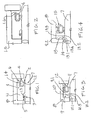
- Figure 1 is a front cross-sectional view of one embodiment of the present rotary, reciprocating, and/or static shaft redundant seal with locking means
- Figure 2 is a front cross-sectional view of another embodiment of the present rotary, reciprocating, and/or static shaft redundant seal with locking means;
- Figure 3 is a front cross-sectional view of another embodiment of the present rotary, reciprocating, and/or static shaft redundant seal with locking means;
- Figure 4 is a front cross-sectional view of another embodiment of the present rotary, reciprocating, and/or static shaft redundant seal with locking means;
- Figure 5 is a front cross-sectional view of another embodiment of the present rotary, reciprocating, and/or static shaft redundant seal with locking means
- Figure 6 is a front cross-sectional view of another embodiment of the present rotary, reciprocating, and/or static shaft redundant seal with locking means
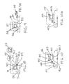
- Figure 7 is a front cross-sectional view of another embodiment of the present rotary, reciprocating, and/or static shaft redundant seal with locking means
- Figure 7A is a detail view of the rotary, reciprocating, and/or static shaft redundant seal with locking means of Figure 7 showing an alternative configuration of the secondary seal;
- Figure 7B is a detail view of the rotary, reciprocating, and/or static shaft redundant seal with locking means of Figure 7 showing an alternative configuration of the secondary seal;
- Figure 8 is a front cross-sectional view of another embodiment of the present rotary, reciprocating, and/or static shaft redundant seal with locking means
- Figure 8A is a detail view of the rotary, reciprocating, and/or static shaft redundant seal with locking means of Figure 8 showing an alternative configuration of the secondary seal;
- Figure 8B is a detail view of the rotary, reciprocating, and/or static shaft redundant seal with locking means of Figure 8 showing an alternative configuration of the secondary seal;
- Figure 9 is a front cross-sectional view of another embodiment of the present rotary, reciprocating, and/or static shaft redundant seal with locking means
- Figure 9A is a detail view of the rotary, reciprocating, and/or static shaft redundant seal with locking means of Figure 9 showing an alternative configuration of the secondary seal;
- Figure 10 is a front cross-sectional view of another embodiment of the present rotary, reciprocating, and/or static shaft redundant seal with locking means;
- Figure 10A is a front cross-sectional view of another embodiment of the present rotary, reciprocating, and/or static shaft redundant seal with locking means;
- Figure 11 is a front cross-sectional view of another embodiment of the present rotary, reciprocating, and/or static shaft redundant seal with locking means;
- Figure 11A is a detail view of the circled portion of the rotary, reciprocating, and/or static shaft redundant seal with locking means of Figure 11 ;
- Figure 11B is a front cross-sectional view of another embodiment of the present rotary, reciprocating, and/or static shaft redundant seal with locking means
- Figure 11C is a detail view of the circled portion of the rotary, reciprocating, and/or static shaft redundant seal with locking means of Figure 11B ;
- Figure 11D is a front cross-sectional view of another embodiment of the present rotary, reciprocating, and/or static shaft redundant seal with locking means.
- Figure 11E is a detail view of the circled portion of the rotary, reciprocating, and/or static shaft redundant seal with locking means of Figure 11D .
- the embodiments illustrated herein describe spring-energized seals.
- the springs used in the present embodiments may comprise canted-coil springs.
- Other energizers including O-rings, "V" springs, finger springs, etc., can be used in place of or in conjunction with the canted coil spring.
- the coil springs may be radially canted, while in certain other embodiments the coil springs may be axially canted. In still further embodiments, the coil springs may be both radially canted and axially canted.
- Canted-coil springs are described in detail in U.S. Patent Nos.
- Figure 1 shows one embodiment of the present rotary, reciprocating, and/or static shaft redundant seal assembly with locking means.
- Redundant indicates that the two seals are incorporated into a single unit, as opposed to two sealing grooves forming part of an assembly whereby various seals are included.
- Redundant seal 1 comprises primary seal 2 energized by a spring 4 and a secondary seal 3 energized by a spring 5, both providing sealing against shaft 7.
- the redundant seal 1 comprises a cavity in which spring 4 and locking ring 6 is retained.
- the locking ring 6 retains and resists rotation or axial movement of the redundant seal 1 and thus the entire sealing assembly in retained in the housing 8 by creating interference between the locking ring 6 and the housing 8.
- a seal body 1.1 comprising two spaced apart seal lips 1.2, 1.3. As shown, the primary seal lip 1.2 is larger than the secondary seal lip 1.3, both in length, thickness, and cavity for receiving a respective energizer.
- the seal body may be made from an elastomer material or a thermoplastic elastomer (TPE) material of the type selected for the operating conditions.
- TPE thermoplastic elastomer
- the locking ring 6 engages the seal body and forms parts of the cavity 1.4 for retaining the primary loading spring 4.
- Figure 2 shows an alternative embodiment of a redundant seal 1.5 similar to Figure 1 , except that the locking ring is omitted.
- a retaining lip 1.6 is formed with the seal body for retaining the loading spring 4.
- the seal of Figure 2 is particularly advantageous for reciprocating shaft applications.
- Figure 3 shows another embodiment in which a triangular or inverted-V scraper 10 is incorporated into the inside diameter of the seal 9, which is energized by a spring 11, to act as a backup scraper to the seal 9.
- the seal 9 comprises a cavity in which the spring 11 and a locking ring 12 are retained.
- the locking ring 12 retains and resists rotation or axial movement of the seal assembly in housing 8 by creating interference between locking ring 12 and housing 8.
- the scraper 10 may be considered as an additional seal, in this instance a secondary seal.
- a feature of the present device, assembly and method includes a backup scraper 10 having a generally triangular shape, which in one embodiment is a V-shape.
- the backup scraper 10 is positioned further away from a high pressure source than the seal 9.
- the backup scraper 10 is made from a harder material than the seal body 9.1, such as from an engineered plastic or a metal, and resists seal extruding, such as by providing axial support for the seal along the direction of the shaft 7.
- the backup scraper 10 comprises two spaced apart scraper edges 10.1, 10.2, which are separated from one another by a space 10.3, which in one example has a V-shaped contour.
- a still yet further feature of the present embodiment is a method of making the seal and method of using the seal.
- Exemplary engineered plastic includes polycarbonates (PC), polyamides (PA), polybutylene terephthalate (PBT), polyethylene terephthalate (PET), polyphenylene oxide (PPO), polysulphone (PSU), polyetherketone (PEK), polyetheretherketone (PEEK), polyimides, and polyphenylene sulfide (PPS).
- PC polycarbonates
- PA polyamides
- PBT polybutylene terephthalate
- PET polyethylene terephthalate
- PPO polyphenylene oxide
- PSU polysulphone
- PEK polyetherketone
- PEEK polyetheretherketone
- polyimides polyimides
- PPS polyphenylene sulfide
- Figure 4 shows an alternative embodiment similar to Figure 3 that includes a different type of backup ring 13.
- the backup ring 13 is similar in design to the one in Figure 3 , but is locked into the internal end portion of the seal 14, which improves retention during use.
- the backup ring 13 is also located in the internal end portion of the seal 14 to resist extrusion of the seal material and as shown contacts the housing 8.
- the backup ring 13 includes a circumferential tapered groove 13A to reduce the contact area between the backup ring 13 and the shaft 7 to reduce heat generated by friction.
- the scraper surfaces or edges 13.1, 13.2 are made narrower lengthwise compared to if the groove 13A was straight or not as tapered.
- a locking ring 15 resists the seal moving in a rotating or reciprocating manner.
- the backup ring 13 has a projection 13.3 that projects into the seal body 9.2 and contacts the housing 8.
- the backup ring 13 contacts the seal body 9.2, the housing 8, and the shaft 7, simultaneously.
- Figure 5 shows an alternative embodiment similar to Figure 4 that is particularly advantageous for reciprocating applications.
- the embodiment of Figure 5 includes no locking ring, since under conditions of high pressure the seal 16 is usually forced toward the end of the cavity. There is thus less incentive to have a locking ring to resist axial movement.
- Figure 6 shows an alternative embodiment that includes two seals.
- Primary seal 17 is energized by a spring 20 and secondary seal 18 is energized by a spring 21.
- the two seals are incorporated into one assembly and are held together by an integrated locking ring 19.
- the locking ring 19 may comprise a material, such as a plastic, that provides locking and sealing in combination with the secondary seal 18.
- the primary seal 17 offers superior sealing ability compared to the secondary seal 18.
- certain material properties such as an elastomer or a TPE
- the seal lip is more pliable and seals against the shaft better than the secondary seal 18, which may be made from a high modulus material and therefore has relatively lesser sealing ability.
- a feature of the present embodiment is a combination locking ring 19 that engages with a primary seal 17 and that has a sealing lip 18.1 and a cavity having an energizer 21 disposed therein for energizing the sealing lip 18.1 towards the shaft 7.
- a further feature of the present seal assembly is a secondary seal 18 that is positioned closer to a high pressure source than the primary seal 17 to reduce abrasive and/or contaminants from reaching the primary seal.
- a still further feature of the present seal assembly is a locking ring 19 that engages a primary seal 17, that has a sealing lip 18.1 to provide secondary sealing, and that forms part of a cavity 17.1 for retaining a primary energizer 17.2.
- a still yet further feature of the present embodiment is a method of making the alternative seal and method of using the alternative seal.
- Figure 7 shows an alternative embodiment similar to Figure 6 except that the secondary seal 24 has been replaced with a memory liplike seal 23 instead of a spring energized seal.
- the liplike seal has elastic properties that allow it to bias against the shaft 7 without an energizer.
- Figure 7A shows another alternative embodiment in which a garter spring 26 is incorporated into the secondary seal 23 to provide radial force to increase sealing ability at the lip.
- Figure 7B shows another alternative embodiment in which a toroidal O-ring 27 provides the radial sealing force.
- Figure 8 shows an alternative embodiment of the present rotary, reciprocating, and/or static shaft seal assembly having a primary seal 28 energized by a spring 31 and a secondary seal 29.
- the secondary seal 29 is part of the locking ring 30 and includes a toroidal O-ring or rectangular cross-section O-ring 29.1 located within a groove 29.2 to provide secondary sealing against the shaft 7.
- the sealing ring is detachable from the groove 29.2.
- the locking ring 30 comprises a flange 30.1 having the groove 29.2 formed at a radial end thereof.
- the locking ring 30, and in particular the flange 30.1 contacts the spring 31 and forms part of the cavity for retaining the spring 31.
- the locking ring 30 provides a support that allows for the mounting of the secondary seal, thus providing sealing ability between the shaft 7 and the locking ring 30.
- Figure 8A shows an alternate embodiment including a circumferential seal 32 having a small contact area 32.1 with the shaft.
- Figure 8B shows an alternate embodiment of the secondary seal in which an extension garter spring 33 provides additional energizing force to affect sealing.
- a still yet further feature of the present embodiment is a method of making the seal assembly and method of using the seal assembly.
- Figure 9 shows an alternative embodiment comprising a dual in-line sealing system with locking ring 37 and primary seal 34 having an energizer 38, such as a canted coil spring.
- the secondary seal 35 may be molded integrally with the locking ring 37 or separately molded and bonded or engaged to the locking ring.
- the seal lip 35.1 of the secondary seal may be made from a high modulus material to reduce abrasive and/or contaminants from reaching the primary seal or may be made from a softer material, such as an elastomer or a TPE, that engages the locking ring.
- Figure 9A shows an alternative embodiment of the secondary seal 37 in which the secondary seal 39 is energized with a canted-coil spring 39A.
- Figure 10 shows an alternative embodiment comprising a redundant rotary, reciprocating, and/or static shaft seal assembly with a locking ring 44.
- the secondary seal 41 is located rearward from the primary seal 40 and functions primarily as a dust seal.
- the secondary seal 41 is energized with a canted-coil spring 43.
- the locking ring 44 retains the seal in the housing 45.
- the seal body 40.1 thus comprises both the primary sealing lip 10.2 and secondary sealing lip 41.1.
- a feature of the present seal assembly is a double seal comprising a singularly formed seal body that is energized by two energizers.
- a still further feature is a singularly formed seal body that has two sealing lips and two energizers and wherein the energizers energize the two sealing lips.
- Figure 10A shows an alternative embodiment similar to Figure 10 in which no locking ring is provided to retain the seal in position. Instead, a support ring 47 retained the seal in the housing 46. Also shown are primary sealing lip 40.5 and secondary sealing lip 40.6.
- Figure 11 shows an alternative embodiment in which a single locking ring 50 retains two separate seals, primary seal 48 and secondary seal 49, thus providing a rotary, reciprocating, and/or static shaft dual seal spring energized by springs 51 and 52.
- the single locking ring 50 may be retained in the housing 8 by pressing the locking ring into the housing with an interference between the outside diameter of the locking ring and the inside diameter of the housing 8.
- Figure 11A shows a detail view of the circled section of Figure 11 , outlining the manner in which the locking or engagement is achieved between the interference of the locking ring outside diameter and the housing inside diameter.
- the locking ring 50 has a plus "+" shape cross-section comprising a vertical arm 50.1 and a crossing horizontal arm 50.2.
- both the primary seal body 48.1 and the secondary seal body 49.1 are made from a pliable material, such as an appropriate elastomer or TPE material.
- the secondary seal body 49.1 is made from a more rigid material than the primary seal body 48.1, such as a high modulus material, for example engineered plastic or metal.
- Figure 11B shows an alternative embodiment similar to Figure 11 in which a variation of the locking ring 50.5 includes a circumferential groove 53 that reduces the area of contact at the interference between the outside diameter of the locking ring and the housing diameter.
- Figure 11C shows a detail view of the circled section of Figure 11B , outlining the circumferential groove 53 and the manner in which the engagement is achieved between the interference of the locking ring outside diameter and the housing inside diameter.
- Figure 11D shows yet another alternative embodiment similar to Figures 11 and 11B in which an axial groove 54 includes a cantilever spring 55 that allows for variation in tolerances due to the deflection of the cantilever spring 55, thus affording greater variation in tolerances and facilitating ease of manufacturing.
- Figure 11E shows a detail view of the circled section of Figure 11D , outlining the manner in which the interference occurs between the outside diameter of the locking ring and the inside diameter of the housing.
- the present seal assemblies for rotary, reciprocating, and/or static shafts and static applications offers a series of double-sealing seal assemblies with multiple design features such as increased sturdiness, resistance to rotation, resistance to axial movement, and extrusion resistance.
- the present seal assemblies also offer increased seal life through using a secondary seal to provide initial moderate sealing against abrasive particles or contaminants to reduce the exposure and wear of the primary seal.
- the present assemblies also provide a back up seal that can provide moderate sealing if the primary seal happens to fail or leak, all resulting in enhanced performance and reliability.
Landscapes
- Engineering & Computer Science (AREA)
- General Engineering & Computer Science (AREA)
- Mechanical Engineering (AREA)
- Sealing With Elastic Sealing Lips (AREA)
- Sealing Devices (AREA)
Abstract
Description
- This is a regular utility application of provisional application Ser. No.
61/162,431 filed March 23, 2009 - The present invention relates to shaft seals for use in rotary, reciprocating, and static applications.
- Shaft seals generally include a seal that extends around a shaft and prevents the passage of lubricant from a relatively high pressure area on a first side of the seal to a relatively low pressure area on a second side of the seal. In some embodiments, these seals are energized by circular springs to provide energized force to the seal to keep the seal in contact with the rotating or reciprocating shaft.
- The various embodiments of the present seal assemblies for rotary, reciprocating, and/or static shafts have several features, no single one of which is solely responsible for their desirable attributes. Embodiments of the present seal assemblies for rotary, reciprocating, and/or static shafts include redundant or dual seals and may include various locking rings. Without limiting the scope of the present embodiments as expressed by the claims that follow, their more prominent features will now be discussed briefly. After considering this discussion, and particularly after reading the section entitled Detailed Description, one will understand how the features of the present embodiments provide advantages, which include increased sturdiness, resistance to rotation, resistance to axial movement, and extrusion resistance, among others. The secondary seal provides initial moderate sealing against abrasive particles or contaminants to reduce the exposure and wear of the primary seal. The present embodiments achieve enhanced performance, reliability, and improved seal life, among others.
- One aspect of the present seal assemblies includes the realization that with conventional rotary, liplike, energized seals, the single energized sealing lip or single sealing component may not be enough to provide complete sealing in some applications. In the event that the seal leaks or fails, a secondary seal would be very beneficial to the sealing component to provide backup or redundant sealing ability on a temporary basis. A feature of the present assembly is the structure and arrangement of components to enable incorporation of a secondary seal into a small and often confined space.
- One embodiment of the present seal assembly is configured for sealing around a movable or static shaft. The seal assembly comprises a primary seal engaging the shaft at a first location. The seal assembly further comprises a secondary seal engaging the shaft at a second location spaced apart from the first location. The seal assembly further comprises a locking ring for retaining the primary and secondary seals with respect to the shaft. The primary seal is constructed of a first material and the secondary seal is constructed of a second material. The second material has a higher modulus of elasticity than the first material.
- Another embodiment of the present seal assembly is configured for sealing around a movable or static shaft. The seal assembly comprises a primary seal engaging the shaft at a first location. The seal assembly further comprises a secondary seal engaging the shaft at a second location spaced apart from the first location. The seal assembly further comprises a locking ring for retaining the primary and secondary seals with respect to the shaft. The locking ring and the secondary seal comprise a unitary component.
- Another embodiment of the present seal assembly is configured for sealing around a movable or static shaft. The seal assembly comprises a primary seal engaging the shaft at a first location. The seal assembly further comprises a locking ring for retaining the primary seal with respect to the shaft. A portion of the locking ring comprises a secondary seal engaging the shaft at a second location spaced apart from the first location.
- Another embodiment of the present seal assembly is configured for sealing around a movable or static shaft. The seal assembly comprises a primary seal engaging the shaft at a first location. The seal assembly further comprises a secondary seal engaging the shaft at a second location spaced apart from the first location. The seal assembly further comprises a housing containing the primary and secondary seals. The seal assembly further comprises a locking ring for retaining the primary and secondary seals with respect to the housing and the shaft. The locking ring includes a circumferential groove that reduces a contact area between the locking ring and the housing.
- Another embodiment of the present seal assembly is configured for sealing around a movable or static shaft. The seal assembly comprises a primary seal engaging the shaft at a first location. A secondary seal engaging the shaft at a second location spaced apart from the first location. Wherein one of the primary seal and the secondary seal is constructed of a first material and the other of the primary seal and the secondary seal is constructed of a second material, and the second material has a higher modulus of elasticity than the first material.
- The various embodiments of the present seal assemblies now will be discussed in detail with an emphasis on highlighting the advantageous features. These embodiments depict the novel and non-obvious seal assemblies shown in the accompanying drawings, which are for illustrative purposes only. These drawings include the following figures, in which like numerals indicate like parts:
-
Figure 1 is a front cross-sectional view of one embodiment of the present rotary, reciprocating, and/or static shaft redundant seal with locking means; -
Figure 2 is a front cross-sectional view of another embodiment of the present rotary, reciprocating, and/or static shaft redundant seal with locking means; -
Figure 3 is a front cross-sectional view of another embodiment of the present rotary, reciprocating, and/or static shaft redundant seal with locking means; -
Figure 4 is a front cross-sectional view of another embodiment of the present rotary, reciprocating, and/or static shaft redundant seal with locking means; -
Figure 5 is a front cross-sectional view of another embodiment of the present rotary, reciprocating, and/or static shaft redundant seal with locking means; -
Figure 6 is a front cross-sectional view of another embodiment of the present rotary, reciprocating, and/or static shaft redundant seal with locking means; -
Figure 7 is a front cross-sectional view of another embodiment of the present rotary, reciprocating, and/or static shaft redundant seal with locking means; -
Figure 7A is a detail view of the rotary, reciprocating, and/or static shaft redundant seal with locking means ofFigure 7 showing an alternative configuration of the secondary seal; -
Figure 7B is a detail view of the rotary, reciprocating, and/or static shaft redundant seal with locking means ofFigure 7 showing an alternative configuration of the secondary seal; -
Figure 8 is a front cross-sectional view of another embodiment of the present rotary, reciprocating, and/or static shaft redundant seal with locking means; -
Figure 8A is a detail view of the rotary, reciprocating, and/or static shaft redundant seal with locking means ofFigure 8 showing an alternative configuration of the secondary seal; -
Figure 8B is a detail view of the rotary, reciprocating, and/or static shaft redundant seal with locking means ofFigure 8 showing an alternative configuration of the secondary seal; -
Figure 9 is a front cross-sectional view of another embodiment of the present rotary, reciprocating, and/or static shaft redundant seal with locking means; -
Figure 9A is a detail view of the rotary, reciprocating, and/or static shaft redundant seal with locking means ofFigure 9 showing an alternative configuration of the secondary seal; -
Figure 10 is a front cross-sectional view of another embodiment of the present rotary, reciprocating, and/or static shaft redundant seal with locking means; -
Figure 10A is a front cross-sectional view of another embodiment of the present rotary, reciprocating, and/or static shaft redundant seal with locking means; -
Figure 11 is a front cross-sectional view of another embodiment of the present rotary, reciprocating, and/or static shaft redundant seal with locking means; -
Figure 11A is a detail view of the circled portion of the rotary, reciprocating, and/or static shaft redundant seal with locking means ofFigure 11 ; -
Figure 11B is a front cross-sectional view of another embodiment of the present rotary, reciprocating, and/or static shaft redundant seal with locking means -
Figure 11C is a detail view of the circled portion of the rotary, reciprocating, and/or static shaft redundant seal with locking means ofFigure 11B ; -
Figure 11D is a front cross-sectional view of another embodiment of the present rotary, reciprocating, and/or static shaft redundant seal with locking means; and -
Figure 11E is a detail view of the circled portion of the rotary, reciprocating, and/or static shaft redundant seal with locking means ofFigure 11D . - The following detailed description describes the present embodiments with reference to the drawings. In the drawings, reference numbers label elements of the present embodiments. These reference numbers are reproduced below in connection with the discussion of the corresponding drawing features.
- The embodiments illustrated herein describe spring-energized seals. The springs used in the present embodiments may comprise canted-coil springs. Other energizers, including O-rings, "V" springs, finger springs, etc., can be used in place of or in conjunction with the canted coil spring. In certain embodiments, the coil springs may be radially canted, while in certain other embodiments the coil springs may be axially canted. In still further embodiments, the coil springs may be both radially canted and axially canted. Canted-coil springs are described in detail in
U.S. Patent Nos. 4,655,462 ;4,826,144 ;4,876781 ;4,907,788 ;4,915,366 ;4,964,204 ;5,139,243 ;5,160,122 ;5,503,375 ;5,615,870 ;5,709,371 ;5,791,638 ; and7,055,812 . The contents of each of the foregoing patents are hereby expressly incorporated herein b y reference. -
Figure 1 shows one embodiment of the present rotary, reciprocating, and/or static shaft redundant seal assembly with locking means. Redundant, in this case, indicates that the two seals are incorporated into a single unit, as opposed to two sealing grooves forming part of an assembly whereby various seals are included.Redundant seal 1 comprisesprimary seal 2 energized by aspring 4 and asecondary seal 3 energized by a spring 5, both providing sealing againstshaft 7. Theredundant seal 1 comprises a cavity in whichspring 4 and lockingring 6 is retained. Thelocking ring 6 retains and resists rotation or axial movement of theredundant seal 1 and thus the entire sealing assembly in retained in the housing 8 by creating interference between the lockingring 6 and the housing 8. - In one example, a seal body 1.1 is provided comprising two spaced apart seal lips 1.2, 1.3. As shown, the primary seal lip 1.2 is larger than the secondary seal lip 1.3, both in length, thickness, and cavity for receiving a respective energizer. The seal body may be made from an elastomer material or a thermoplastic elastomer (TPE) material of the type selected for the operating conditions. In addition, as shown, the
locking ring 6 engages the seal body and forms parts of the cavity 1.4 for retaining theprimary loading spring 4. -
Figure 2 shows an alternative embodiment of a redundant seal 1.5 similar toFigure 1 , except that the locking ring is omitted. A retaining lip 1.6 is formed with the seal body for retaining theloading spring 4. The seal ofFigure 2 is particularly advantageous for reciprocating shaft applications. -
Figure 3 shows another embodiment in which a triangular or inverted-V scraper 10 is incorporated into the inside diameter of theseal 9, which is energized by a spring 11, to act as a backup scraper to theseal 9. Theseal 9 comprises a cavity in which the spring 11 and alocking ring 12 are retained. The lockingring 12 retains and resists rotation or axial movement of the seal assembly in housing 8 by creating interference between lockingring 12 and housing 8. Thescraper 10 may be considered as an additional seal, in this instance a secondary seal. - Under conditions of elevated pressure and temperature, the
scraper backup ring 10 resists theseal 9 extruding, thus increasing seal life. The reduction in area due to the triangular cross-section of thescraper 10 compared to, for example, a cavity with an energizer is preferred since the compactness of the scraper backup ring allows for greater retention of the triangular shape into the inside diameter of theseal 9. In turn, the arrangement provides a greater degree of retention and limits the extrusion of the seal plastic at elevated temperatures. Thus, a feature of the present device, assembly and method includes abackup scraper 10 having a generally triangular shape, which in one embodiment is a V-shape. In one example, thebackup scraper 10 is positioned further away from a high pressure source than theseal 9. In another example, thebackup scraper 10 is made from a harder material than the seal body 9.1, such as from an engineered plastic or a metal, and resists seal extruding, such as by providing axial support for the seal along the direction of theshaft 7. In still yet another embodiment, thebackup scraper 10 comprises two spaced apart scraper edges 10.1, 10.2, which are separated from one another by a space 10.3, which in one example has a V-shaped contour. A still yet further feature of the present embodiment is a method of making the seal and method of using the seal. Exemplary engineered plastic includes polycarbonates (PC), polyamides (PA), polybutylene terephthalate (PBT), polyethylene terephthalate (PET), polyphenylene oxide (PPO), polysulphone (PSU), polyetherketone (PEK), polyetheretherketone (PEEK), polyimides, and polyphenylene sulfide (PPS). -
Figure 4 shows an alternative embodiment similar toFigure 3 that includes a different type ofbackup ring 13. Thebackup ring 13 is similar in design to the one inFigure 3 , but is locked into the internal end portion of theseal 14, which improves retention during use. Thebackup ring 13 is also located in the internal end portion of theseal 14 to resist extrusion of the seal material and as shown contacts the housing 8. Thebackup ring 13 includes a circumferentialtapered groove 13A to reduce the contact area between thebackup ring 13 and theshaft 7 to reduce heat generated by friction. In other words, the scraper surfaces or edges 13.1, 13.2 are made narrower lengthwise compared to if thegroove 13A was straight or not as tapered. A lockingring 15 resists the seal moving in a rotating or reciprocating manner. As shown, thebackup ring 13 has a projection 13.3 that projects into the seal body 9.2 and contacts the housing 8. In another example, thebackup ring 13 contacts the seal body 9.2, the housing 8, and theshaft 7, simultaneously. -
Figure 5 shows an alternative embodiment similar toFigure 4 that is particularly advantageous for reciprocating applications. The embodiment ofFigure 5 includes no locking ring, since under conditions of high pressure theseal 16 is usually forced toward the end of the cavity. There is thus less incentive to have a locking ring to resist axial movement. -
Figure 6 shows an alternative embodiment that includes two seals.Primary seal 17 is energized by aspring 20 andsecondary seal 18 is energized by aspring 21. The two seals are incorporated into one assembly and are held together by anintegrated locking ring 19. The lockingring 19 may comprise a material, such as a plastic, that provides locking and sealing in combination with thesecondary seal 18. In one embodiment, theprimary seal 17 offers superior sealing ability compared to thesecondary seal 18. For example, by incorporating certain material properties, such as an elastomer or a TPE, the seal lip is more pliable and seals against the shaft better than thesecondary seal 18, which may be made from a high modulus material and therefore has relatively lesser sealing ability. However, by using a high modulus material, the secondary seal provides moderate sealing of abrasive and/or contaminants to thereby reduce the exposure and wear of theprimary seal 17. The lockingring 19 retains the two seals in one assembly unit. In an alternative embodiment, the lockingring 19 may be omitted, leaving a primary seal and a secondary seal, with one or the other of the seals being made from a high modulus material. Thus, a feature of the present embodiment is acombination locking ring 19 that engages with aprimary seal 17 and that has a sealing lip 18.1 and a cavity having anenergizer 21 disposed therein for energizing the sealing lip 18.1 towards theshaft 7. A further feature of the present seal assembly is asecondary seal 18 that is positioned closer to a high pressure source than theprimary seal 17 to reduce abrasive and/or contaminants from reaching the primary seal. A still further feature of the present seal assembly is a lockingring 19 that engages aprimary seal 17, that has a sealing lip 18.1 to provide secondary sealing, and that forms part of a cavity 17.1 for retaining a primary energizer 17.2. A still yet further feature of the present embodiment is a method of making the alternative seal and method of using the alternative seal. -
Figure 7 shows an alternative embodiment similar toFigure 6 except that thesecondary seal 24 has been replaced with amemory liplike seal 23 instead of a spring energized seal. In other words, the liplike seal has elastic properties that allow it to bias against theshaft 7 without an energizer.Figure 7A shows another alternative embodiment in which agarter spring 26 is incorporated into thesecondary seal 23 to provide radial force to increase sealing ability at the lip.Figure 7B shows another alternative embodiment in which a toroidal O-ring 27 provides the radial sealing force. -
Figure 8 shows an alternative embodiment of the present rotary, reciprocating, and/or static shaft seal assembly having aprimary seal 28 energized by aspring 31 and asecondary seal 29. Thesecondary seal 29 is part of the lockingring 30 and includes a toroidal O-ring or rectangular cross-section O-ring 29.1 located within a groove 29.2 to provide secondary sealing against theshaft 7. The sealing ring is detachable from the groove 29.2. As shown, the lockingring 30 comprises a flange 30.1 having the groove 29.2 formed at a radial end thereof. The lockingring 30, and in particular the flange 30.1, contacts thespring 31 and forms part of the cavity for retaining thespring 31. The lockingring 30 provides a support that allows for the mounting of the secondary seal, thus providing sealing ability between theshaft 7 and the lockingring 30. Figure 8A shows an alternate embodiment including acircumferential seal 32 having a small contact area 32.1 with the shaft. Figure 8B shows an alternate embodiment of the secondary seal in which anextension garter spring 33 provides additional energizing force to affect sealing. A still yet further feature of the present embodiment is a method of making the seal assembly and method of using the seal assembly. -
Figure 9 shows an alternative embodiment comprising a dual in-line sealing system with lockingring 37 andprimary seal 34 having anenergizer 38, such as a canted coil spring. Thesecondary seal 35 may be molded integrally with the lockingring 37 or separately molded and bonded or engaged to the locking ring. The seal lip 35.1 of the secondary seal may be made from a high modulus material to reduce abrasive and/or contaminants from reaching the primary seal or may be made from a softer material, such as an elastomer or a TPE, that engages the locking ring.Figure 9A shows an alternative embodiment of thesecondary seal 37 in which the secondary seal 39 is energized with a canted-coil spring 39A. -
Figure 10 shows an alternative embodiment comprising a redundant rotary, reciprocating, and/or static shaft seal assembly with a lockingring 44. Thesecondary seal 41 is located rearward from theprimary seal 40 and functions primarily as a dust seal. Thesecondary seal 41 is energized with a canted-coil spring 43. The lockingring 44 retains the seal in thehousing 45. The seal body 40.1 thus comprises both the primary sealing lip 10.2 and secondary sealing lip 41.1. Thus, a feature of the present seal assembly is a double seal comprising a singularly formed seal body that is energized by two energizers. A still further feature is a singularly formed seal body that has two sealing lips and two energizers and wherein the energizers energize the two sealing lips.Figure 10A shows an alternative embodiment similar toFigure 10 in which no locking ring is provided to retain the seal in position. Instead, asupport ring 47 retained the seal in thehousing 46. Also shown are primary sealing lip 40.5 and secondary sealing lip 40.6. -
Figure 11 shows an alternative embodiment in which asingle locking ring 50 retains two separate seals,primary seal 48 and secondary seal 49, thus providing a rotary, reciprocating, and/or static shaft dual seal spring energized bysprings single locking ring 50 may be retained in the housing 8 by pressing the locking ring into the housing with an interference between the outside diameter of the locking ring and the inside diameter of the housing 8.Figure 11A shows a detail view of the circled section ofFigure 11 , outlining the manner in which the locking or engagement is achieved between the interference of the locking ring outside diameter and the housing inside diameter. As shown, the lockingring 50 has a plus "+" shape cross-section comprising a vertical arm 50.1 and a crossing horizontal arm 50.2. In one example, both the primary seal body 48.1 and the secondary seal body 49.1 are made from a pliable material, such as an appropriate elastomer or TPE material. In another example, the secondary seal body 49.1 is made from a more rigid material than the primary seal body 48.1, such as a high modulus material, for example engineered plastic or metal. -
Figure 11B shows an alternative embodiment similar toFigure 11 in which a variation of the locking ring 50.5 includes acircumferential groove 53 that reduces the area of contact at the interference between the outside diameter of the locking ring and the housing diameter.Figure 11C shows a detail view of the circled section ofFigure 11B , outlining thecircumferential groove 53 and the manner in which the engagement is achieved between the interference of the locking ring outside diameter and the housing inside diameter. -
Figure 11D shows yet another alternative embodiment similar toFigures 11 and 11B in which anaxial groove 54 includes acantilever spring 55 that allows for variation in tolerances due to the deflection of thecantilever spring 55, thus affording greater variation in tolerances and facilitating ease of manufacturing.Figure 11E shows a detail view of the circled section ofFigure 11D , outlining the manner in which the interference occurs between the outside diameter of the locking ring and the inside diameter of the housing. - The present seal assemblies for rotary, reciprocating, and/or static shafts and static applications offers a series of double-sealing seal assemblies with multiple design features such as increased sturdiness, resistance to rotation, resistance to axial movement, and extrusion resistance. The present seal assemblies also offer increased seal life through using a secondary seal to provide initial moderate sealing against abrasive particles or contaminants to reduce the exposure and wear of the primary seal. The present assemblies also provide a back up seal that can provide moderate sealing if the primary seal happens to fail or leak, all resulting in enhanced performance and reliability.
- The above description presents the best mode contemplated for carrying out the present seal assemblies, and of the manner and process of making and using them, in such full, clear, concise, and exact terms as to enable any person skilled in the art to which it pertains to make and use these seal assemblies. These seal assemblies are, however, susceptible to modifications and alternate constructions from that discussed above that are fully equivalent. Consequently, these seal assemblies are not limited to the particular embodiments disclosed. On the contrary, these seal assemblies cover all modifications and alternate constructions coming within the spirit and scope of the seal assemblies as generally expressed by the following claims, which particularly point out and distinctly claim the subject matter of the seal assemblies.
Claims (17)
- A seal assembly for sealing around a moveable or static shaft, comprising:a primary seal engaging the shaft at a first location;a secondary seal engaging the shaft at a second location spaced apart from the first location; anda locking ring for retaining the primary and secondary seals with respect to the shaft;wherein the primary seal is constructed of a first material and the secondary seal is constructed of a second material, and the second material has a higher modulus of elasticity than the first material.
- The seal assembly of claim 1, wherein the first material is at least one of an elastomer material and a thermoplastic elastomer (TPE) material.
- The seal assembly of claim 1, wherein the second material is at least one of a metal and an engineered plastic.
- The seal assembly of claim 1, wherein the locking ring forms at least part of the secondary seal including a seal lip.
- The seal assembly of claim 1, wherein the locking ring includes a circumferential groove that reduces a contact area between the locking ring and a housing.
- The seal assembly of claim 1, wherein the secondary seal is a scraper.
- The seal assembly of claim 6, wherein the scraper comprises two spaced apart scraping edges.
- A seal assembly for sealing around a moveable or static shaft, comprising:a primary seal engaging the shaft at a first location;a secondary seal engaging the shaft at a second location spaced apart from the first location; anda locking ring for retaining the primary and secondary seals with respect to the shaft;wherein the locking ring and the secondary seal comprise a unitary component.
- The seal assembly of claim 8, further comprising an energizer in contact with the primary seal.
- The seal assembly of claim 9, wherein the energizer is in contact with the locking ring, which forms part of a cavity of the primary seal.
- The seal assembly of claim 8, wherein the secondary seal is a memory lip seal not in contact with an energizer.
- The seal assembly of claim 8, wherein the secondary seal comprises a groove having a detachable sealing ring.
- A method for sealing a shaft comprising:placing a seal assembly around the shaft;positioning the assembly such that a primary seal or a secondary seal is located closer to a pressure source than the other one of the primary seal or the secondary seal;wedging a locking ring against a housing to prevent rotation of the seal assembly relative to the housing;providing at least one energizer in mechanical communication with the primary seal to energize a primary seal lip against the shaft.
- The method for sealing of claim 13, wherein the secondary seal and the locking ring are singularly formed.
- The method for sealing of claim 13, further comprising placing a second energizer in mechanical communication with the secondary seal.
- The method for sealing of claim 13, further comprising contacting the at least one energizer with the locking ring.
- The method for sealing of claim 13, wherein the primary seal, the secondary seal, and the locking ring are singularly formed.
Applications Claiming Priority (2)
| Application Number | Priority Date | Filing Date | Title |
|---|---|---|---|
| US16243109P | 2009-03-23 | 2009-03-23 | |
| US12/726,943 US8544850B2 (en) | 2009-03-23 | 2010-03-18 | Seal assemblies for movable and static shafts |
Publications (2)
| Publication Number | Publication Date |
|---|---|
| EP2233799A1 true EP2233799A1 (en) | 2010-09-29 |
| EP2233799B1 EP2233799B1 (en) | 2012-12-12 |
Family
ID=42321120
Family Applications (1)
| Application Number | Title | Priority Date | Filing Date |
|---|---|---|---|
| EP10003007A Active EP2233799B1 (en) | 2009-03-23 | 2010-03-22 | Seal assemblies for movable and static shafts |
Country Status (2)
| Country | Link |
|---|---|
| US (1) | US8544850B2 (en) |
| EP (1) | EP2233799B1 (en) |
Cited By (4)
| Publication number | Priority date | Publication date | Assignee | Title |
|---|---|---|---|---|
| WO2012122445A2 (en) | 2011-03-10 | 2012-09-13 | Waters Technologies Corporation | Seal assemblies for reciprocating and rotary applications |
| EP2846068A3 (en) * | 2013-09-03 | 2015-03-25 | Bal Seal Engineering, Inc. | Elastic seals with dynamic lips and related methods |
| ITUB20152510A1 (en) * | 2015-07-27 | 2017-01-27 | Fluorten S R L | SEAL FOR SEALING A TREE OR A ROTATING OR ALTERNATIVE PISTON. |
| US11536373B2 (en) | 2016-03-07 | 2022-12-27 | Bal Seal Engineering, Llc | Seal assemblies and related methods |
Families Citing this family (41)
| Publication number | Priority date | Publication date | Assignee | Title |
|---|---|---|---|---|
| DE102009019890A1 (en) * | 2009-05-04 | 2010-11-11 | Trw Automotive Gmbh | Rack and pinion steering |
| US10520091B2 (en) * | 2009-07-08 | 2019-12-31 | Bal Seal Engineering, Inc. | Double direction seal with locking |
| US8684362B2 (en) | 2009-08-12 | 2014-04-01 | Bal Seal Engineering, Inc. | Cartridge seal assemblies and associated methods |
| CA2781719A1 (en) * | 2009-12-11 | 2011-06-16 | Saint-Gobain Performance Plastics Corporation | System, method and apparatus for spring-energized dynamic sealing assembly |
| CN102695878B (en) * | 2010-01-14 | 2016-08-03 | 开利公司 | Reciprocal refrigeration compressor oil seal |
| JP5370310B2 (en) * | 2010-08-03 | 2013-12-18 | 株式会社島津製作所 | Feed pump |
| DE102010051403A1 (en) * | 2010-11-16 | 2012-05-16 | Carl Freudenberg Kg | Seal and method for producing a sealing ring |
| DE102011018584A1 (en) * | 2011-04-11 | 2012-10-11 | Blohm + Voss Industries Gmbh | Seal for sealing waves |
| US10125872B2 (en) | 2011-08-18 | 2018-11-13 | Bal Seal Engineering, Inc. | Reciprocating seal for high pulsating pressure |
| DE102012202571A1 (en) * | 2012-02-20 | 2013-08-22 | Trelleborg Sealing Solutions Germany Gmbh | Sealing arrangement and method for its production |
| US20130330122A1 (en) * | 2012-06-12 | 2013-12-12 | Bal Seal Engineering, Inc. | Canted coil springs with contoured wire shapes, related systems, and related methods |
| US9829028B2 (en) * | 2012-11-15 | 2017-11-28 | Bal Seal Engineering, Inc. | Connectors with a pin, a housing, and one or more springs |
| US9228659B2 (en) * | 2013-05-31 | 2016-01-05 | Aktiebolaget Skf | Seal with replaceable lip |
| US10047570B2 (en) | 2013-12-19 | 2018-08-14 | Halliburton Energy Services, Inc. | Energized paek seals |
| US10598241B2 (en) | 2014-02-26 | 2020-03-24 | Bal Seal Engineering, Inc. | Multi deflection canted coil springs and related methods |
| US9869395B2 (en) * | 2014-02-26 | 2018-01-16 | Garlock Sealing Technologies, Llc | Shaft sealing apparatus and associated methods |
| CA3053128C (en) * | 2014-07-09 | 2021-10-19 | Saint-Gobain Performance Plastics Corporation | Polymer seal assembly |
| JP6280010B2 (en) * | 2014-09-25 | 2018-02-14 | ファナック株式会社 | Rotating shaft device and electric discharge machine equipped with the rotating shaft device |
| US10184564B2 (en) | 2015-02-02 | 2019-01-22 | Bal Seal Engineering, Inc. | Seal assemblies and related methods |
| US10117366B2 (en) | 2015-12-14 | 2018-10-30 | Bal Seal Engineering, Inc. | Spring energized seals and related methods |
| US10451061B2 (en) * | 2016-05-06 | 2019-10-22 | Ingersoll-Rand Company | Compressor having non-contact and contact seals |
| US10181668B2 (en) | 2016-06-24 | 2019-01-15 | Bal Seal Engineering, Inc. | Spring contacts and related methods |
| WO2018031443A1 (en) * | 2016-08-08 | 2018-02-15 | Waters Technologies Corporation | Spring-energized check valve |
| US10520092B2 (en) | 2016-10-24 | 2019-12-31 | Bal Seal Engineering, Inc. | Seal assemblies for extreme temperatures and related methods |
| US10989305B2 (en) * | 2016-10-31 | 2021-04-27 | Bal Seal Engineering, Llc | Axial and radial floating seals |
| DE102017203083A1 (en) * | 2017-02-24 | 2018-08-30 | Aktiebolaget Skf | stem seal |
| EP3726103B1 (en) | 2017-03-16 | 2024-02-21 | Bal Seal Engineering, LLC | V-springs, seals with v-springs, and related methods |
| EP3385167A1 (en) * | 2017-04-03 | 2018-10-10 | Adient US LLC | A seat for a vehicle |
| US11739653B2 (en) * | 2017-05-03 | 2023-08-29 | Stein Seal Company | Circumferential seal assembly with adjustable seating forces |
| EP4098845B1 (en) | 2017-05-03 | 2025-03-05 | Stein Seal Company | Improved circumferential seal assembly with adjustable seating forces |
| US10604995B2 (en) * | 2017-06-22 | 2020-03-31 | Sejong Pharmatech Co., Ltd. | Sealing door and method of forming channel |
| US10900531B2 (en) | 2017-08-30 | 2021-01-26 | Bal Seal Engineering, Llc | Spring wire ends to faciliate welding |
| US11353079B2 (en) | 2017-10-05 | 2022-06-07 | Bal Seal Engineering, Llc | Spring assemblies, applications of spring assemblies, and related methods |
| CA3083964C (en) * | 2017-11-30 | 2023-12-12 | Saint-Gobain Performance Plastics Corporation | Seal, assembly, and methods of using the same |
| EP3567285B1 (en) | 2018-05-08 | 2025-01-15 | Bal Seal Engineering, LLC | Seal assemblies and related methods |
| EP3830456B1 (en) * | 2018-08-03 | 2024-09-04 | Saint-Gobain Performance Plastics Corporation | Ball valve seal |
| US11708910B2 (en) * | 2018-12-31 | 2023-07-25 | Saint-Gobain Performance Plastics Corporation | Seals |
| US12092160B2 (en) | 2021-09-23 | 2024-09-17 | Bal Seal Engineering Llc | Integrated seal and bearing assembly and related methods |
| US11940049B1 (en) | 2022-11-01 | 2024-03-26 | Bal Seal Engineering, Llc | Lip seals and related methods |
| US12247663B2 (en) * | 2022-11-01 | 2025-03-11 | Bal Seal Engineering, Llc | Lip seals and related methods |
| US11746906B1 (en) | 2022-11-01 | 2023-09-05 | Bal Seal Engineering, Llc | Lip seals and related methods |
Citations (4)
| Publication number | Priority date | Publication date | Assignee | Title |
|---|---|---|---|---|
| DE839651C (en) | 1950-05-20 | 1952-05-23 | Deutsche Bundesbahn | Seal for locomotive bearings made of elastic, oil and temperature-resistant material |
| US6267383B1 (en) * | 1986-02-25 | 2001-07-31 | John D. Morvant | V-shaped seal with anti-extrusion section |
| EP1598579A1 (en) | 2003-02-27 | 2005-11-23 | EAGLE INDUSTRY Co., Ltd. | Lip-type seal |
| US20060022414A1 (en) | 2004-07-30 | 2006-02-02 | Balsells Peter J | Rotary cartridge seals with composite retainer |
Family Cites Families (37)
| Publication number | Priority date | Publication date | Assignee | Title |
|---|---|---|---|---|
| US2368137A (en) * | 1943-12-22 | 1945-01-30 | Beech Aircraft Corp | Protected packing seal |
| US2651534A (en) * | 1949-06-15 | 1953-09-08 | Victor Mfg & Gasket Co | Sealing device |
| US2833577A (en) * | 1956-12-24 | 1958-05-06 | Chicago Rawhide Mfg Co | Scraper seal |
| US2966376A (en) * | 1958-04-30 | 1960-12-27 | Chicago Rawhide Mfg Co | Shaft seal assembly |
| GB1371610A (en) * | 1970-12-10 | 1974-10-23 | Hall Hall Ltd | Scraper rings |
| US3871665A (en) * | 1973-04-09 | 1975-03-18 | Greene Tweed & Co Inc | Rod wiper assembly |
| DE2442338C2 (en) * | 1974-09-04 | 1982-07-01 | Alfred Teves Gmbh, 6000 Frankfurt | Sealing ring for sealing a pin in a pin bushing |
| US4566701A (en) * | 1983-09-19 | 1986-01-28 | Halliburton Company | Cushioning unit shaft seal |
| JPS60184461U (en) * | 1984-05-17 | 1985-12-06 | エヌオーケー株式会社 | oil seal |
| US5244215A (en) * | 1985-05-10 | 1993-09-14 | Chicago Rawhide Manufacturing Company | Rotary shaft seal with retractable excluder lip |
| DE3765249D1 (en) * | 1986-03-24 | 1990-10-31 | Zahnradfabrik Friedrichshafen | SEALING RING FOR ARRANGEMENT BETWEEN AXIAL AND ROTATING MACHINE PARTS. |
| US4805943A (en) * | 1986-08-15 | 1989-02-21 | Peter J. Balsells | Rotary/reciprocating seal apparatus |
| DE3702977A1 (en) * | 1987-02-02 | 1988-08-18 | Busak & Luyken Gmbh & Co | SEAL AND SCRAPER ARRANGEMENT |
| DE8912315U1 (en) * | 1989-10-17 | 1989-11-30 | Hewlett-Packard GmbH, 7030 Böblingen | Sealing arrangement for a piston pump |
| WO1991013277A1 (en) * | 1990-02-26 | 1991-09-05 | Zahnradfabrik Friedrichshafen Ag | Sealing arrangement |
| US5058487A (en) * | 1990-05-01 | 1991-10-22 | Litton Industrial Automation Systems, Inc. | Cylinder with radially movable rod |
| US5265890A (en) * | 1990-12-03 | 1993-11-30 | Peter J. Balsells | Seal with spring energizer |
| US5199718A (en) * | 1992-04-13 | 1993-04-06 | Vickers, Incorporated | Rotary machine shaft seal |
| US6053502A (en) * | 1995-01-13 | 2000-04-25 | Ab Volvo Penta | Seat for a sealing ring |
| DE19730120A1 (en) * | 1997-07-14 | 1999-01-21 | Gebr Hennig Gmbh | Scraper |
| US5984316A (en) * | 1997-12-12 | 1999-11-16 | Bal Seal Engineering Company, Inc. | Rotary reciprocating seals with internal metal band |
| US5992856A (en) * | 1997-12-12 | 1999-11-30 | Bal Seal Engineering Company, Inc. | Rotary, reciprocating seals with double spring and separating band rings |
| US5979904A (en) * | 1997-12-12 | 1999-11-09 | Bal Seal Engineering Company, Inc. | Rotary reciprocating seals with exterior metal band |
| US6047970A (en) * | 1997-12-22 | 2000-04-11 | Caterpillar Inc. | Rod scraper |
| US6050572A (en) * | 1998-03-09 | 2000-04-18 | Bal Seal Engineering Company, Inc. | Rotary cartridge seals with retainer |
| FR2786547B1 (en) * | 1998-12-01 | 2001-02-16 | Hutchinson | SEAL FOR A ROTATING SHAFT, AND DEVICE COMPRISING SUCH A SEAL |
| US6561519B1 (en) * | 2000-11-08 | 2003-05-13 | Freudenberg-Nok General Partnership | Dual seal |
| WO2002079676A2 (en) * | 2001-03-28 | 2002-10-10 | Balseal Engineering Co., Inc. | Media isolation seal system |
| EP1461548A4 (en) * | 2001-04-18 | 2007-03-14 | Bal Seal Engineering Co | Self contained anti-blowout seal for fluids or gases |
| JP2003120823A (en) * | 2001-10-19 | 2003-04-23 | Eagle Ind Co Ltd | Seal device |
| DE10208936B4 (en) * | 2002-02-28 | 2006-11-02 | Federal-Mogul Sealing Systems Bretten Gmbh | poetry |
| JP2005299808A (en) * | 2004-04-13 | 2005-10-27 | Nok Corp | Seal for pump |
| US8196933B2 (en) * | 2004-07-12 | 2012-06-12 | Skf Usa Inc. | Seal with plastic inner cup |
| US7832735B2 (en) * | 2006-01-11 | 2010-11-16 | Skf Usa Inc. | Seal assembly with protective filter |
| BRPI0621390A2 (en) * | 2006-03-08 | 2011-12-06 | Eagle Ind Co Ltd | sealing device with a snap ring that projects toward a fluid storage chamber to confine a rotary shaft |
| JP4875597B2 (en) * | 2007-11-28 | 2012-02-15 | イーグル工業株式会社 | Lip type seal |
| US8096559B2 (en) * | 2008-05-23 | 2012-01-17 | Bal Seal Engineering, Inc. | Rotary seals |
-
2010
- 2010-03-18 US US12/726,943 patent/US8544850B2/en not_active Expired - Fee Related
- 2010-03-22 EP EP10003007A patent/EP2233799B1/en active Active
Patent Citations (4)
| Publication number | Priority date | Publication date | Assignee | Title |
|---|---|---|---|---|
| DE839651C (en) | 1950-05-20 | 1952-05-23 | Deutsche Bundesbahn | Seal for locomotive bearings made of elastic, oil and temperature-resistant material |
| US6267383B1 (en) * | 1986-02-25 | 2001-07-31 | John D. Morvant | V-shaped seal with anti-extrusion section |
| EP1598579A1 (en) | 2003-02-27 | 2005-11-23 | EAGLE INDUSTRY Co., Ltd. | Lip-type seal |
| US20060022414A1 (en) | 2004-07-30 | 2006-02-02 | Balsells Peter J | Rotary cartridge seals with composite retainer |
Cited By (10)
| Publication number | Priority date | Publication date | Assignee | Title |
|---|---|---|---|---|
| WO2012122445A2 (en) | 2011-03-10 | 2012-09-13 | Waters Technologies Corporation | Seal assemblies for reciprocating and rotary applications |
| CN103403412A (en) * | 2011-03-10 | 2013-11-20 | 沃特世科技公司 | Seal assemblies for reciprocating and rotating applications |
| EP2683968A4 (en) * | 2011-03-10 | 2015-05-27 | Waters Technologies Corp | SEALING ASSEMBLIES FOR RANGE AND ROTATING APPLICATIONS |
| US9488277B2 (en) | 2011-03-10 | 2016-11-08 | Waters Technologies Corporation | Seal assemblies for reciprocating and rotary applications |
| US10302102B2 (en) | 2011-03-10 | 2019-05-28 | Waters Technologies Corporation | Seal assemblies for reciprocating and rotary applications |
| EP2846068A3 (en) * | 2013-09-03 | 2015-03-25 | Bal Seal Engineering, Inc. | Elastic seals with dynamic lips and related methods |
| US9194497B2 (en) | 2013-09-03 | 2015-11-24 | Bal Seal Engineering, Inc. | Elastic seals with dynamic lips and related methods |
| ITUB20152510A1 (en) * | 2015-07-27 | 2017-01-27 | Fluorten S R L | SEAL FOR SEALING A TREE OR A ROTATING OR ALTERNATIVE PISTON. |
| US11536373B2 (en) | 2016-03-07 | 2022-12-27 | Bal Seal Engineering, Llc | Seal assemblies and related methods |
| EP3217046B1 (en) * | 2016-03-07 | 2024-05-01 | Bal Seal Engineering, LLC | Seal assemblies and related methods |
Also Published As
| Publication number | Publication date |
|---|---|
| US20100237566A1 (en) | 2010-09-23 |
| US8544850B2 (en) | 2013-10-01 |
| EP2233799B1 (en) | 2012-12-12 |
Similar Documents
| Publication | Publication Date | Title |
|---|---|---|
| US8544850B2 (en) | Seal assemblies for movable and static shafts | |
| US6161838A (en) | Cartridge seal stack | |
| US10184564B2 (en) | Seal assemblies and related methods | |
| US10520091B2 (en) | Double direction seal with locking | |
| JP5654607B2 (en) | System, method and apparatus for a spring activated dynamic sealing assembly | |
| EP2971879B1 (en) | High pressure lip seals with anti-extrusion and anti-galling properties and related methods | |
| US9512924B2 (en) | Sealing structure | |
| US20060022414A1 (en) | Rotary cartridge seals with composite retainer | |
| CN109642675B (en) | Sealing means | |
| JP5159309B2 (en) | Seal assembly and shaft seal system | |
| MXPA05003406A (en) | Unitizing element and method for assembling a seal. | |
| EP0867647B1 (en) | Seal arrangement including a pair of relatively axially movable coaxial components and a spring energised plastic seal | |
| JP2004308906A (en) | Packing | |
| US7604243B2 (en) | Composite seals, seal structures and related methods | |
| EP1256749A2 (en) | Sealing assembly for relatively rotating mechanical members | |
| US11131387B2 (en) | Sealing ring and seal arrangement comprising such a sealing ring | |
| CN110686036A (en) | Supporting ring | |
| US20070187902A1 (en) | Robust sealing system for power steering input shaft | |
| JP2011112202A (en) | Piston ring | |
| CN110869654B (en) | Central butterfly valve | |
| JP2011058585A (en) | Sealing device | |
| JPH11351401A (en) | Sealing device | |
| JP2008121846A (en) | Backup ring | |
| KR20230145486A (en) | sealing device | |
| JP2007092791A (en) | Seal ring |
Legal Events
| Date | Code | Title | Description |
|---|---|---|---|
| PUAI | Public reference made under article 153(3) epc to a published international application that has entered the european phase |
Free format text: ORIGINAL CODE: 0009012 |
|
| AK | Designated contracting states |
Kind code of ref document: A1 Designated state(s): AT BE BG CH CY CZ DE DK EE ES FI FR GB GR HR HU IE IS IT LI LT LU LV MC MK MT NL NO PL PT RO SE SI SK SM TR |
|
| AX | Request for extension of the european patent |
Extension state: AL BA ME RS |
|
| 17P | Request for examination filed |
Effective date: 20110329 |
|
| 17Q | First examination report despatched |
Effective date: 20110531 |
|
| GRAP | Despatch of communication of intention to grant a patent |
Free format text: ORIGINAL CODE: EPIDOSNIGR1 |
|
| GRAS | Grant fee paid |
Free format text: ORIGINAL CODE: EPIDOSNIGR3 |
|
| GRAA | (expected) grant |
Free format text: ORIGINAL CODE: 0009210 |
|
| AK | Designated contracting states |
Kind code of ref document: B1 Designated state(s): AT BE BG CH CY CZ DE DK EE ES FI FR GB GR HR HU IE IS IT LI LT LU LV MC MK MT NL NO PL PT RO SE SI SK SM TR |
|
| REG | Reference to a national code |
Ref country code: GB Ref legal event code: FG4D |
|
| REG | Reference to a national code |
Ref country code: CH Ref legal event code: EP |
|
| REG | Reference to a national code |
Ref country code: AT Ref legal event code: REF Ref document number: 588488 Country of ref document: AT Kind code of ref document: T Effective date: 20121215 |
|
| REG | Reference to a national code |
Ref country code: IE Ref legal event code: FG4D |
|
| REG | Reference to a national code |
Ref country code: DE Ref legal event code: R096 Ref document number: 602010004005 Country of ref document: DE Effective date: 20130207 |
|
| PG25 | Lapsed in a contracting state [announced via postgrant information from national office to epo] |
Ref country code: NO Free format text: LAPSE BECAUSE OF FAILURE TO SUBMIT A TRANSLATION OF THE DESCRIPTION OR TO PAY THE FEE WITHIN THE PRESCRIBED TIME-LIMIT Effective date: 20130312 Ref country code: FI Free format text: LAPSE BECAUSE OF FAILURE TO SUBMIT A TRANSLATION OF THE DESCRIPTION OR TO PAY THE FEE WITHIN THE PRESCRIBED TIME-LIMIT Effective date: 20121212 Ref country code: SE Free format text: LAPSE BECAUSE OF FAILURE TO SUBMIT A TRANSLATION OF THE DESCRIPTION OR TO PAY THE FEE WITHIN THE PRESCRIBED TIME-LIMIT Effective date: 20121212 Ref country code: ES Free format text: LAPSE BECAUSE OF FAILURE TO SUBMIT A TRANSLATION OF THE DESCRIPTION OR TO PAY THE FEE WITHIN THE PRESCRIBED TIME-LIMIT Effective date: 20130323 Ref country code: LT Free format text: LAPSE BECAUSE OF FAILURE TO SUBMIT A TRANSLATION OF THE DESCRIPTION OR TO PAY THE FEE WITHIN THE PRESCRIBED TIME-LIMIT Effective date: 20121212 |
|
| REG | Reference to a national code |
Ref country code: NL Ref legal event code: VDEP Effective date: 20121212 |
|
| REG | Reference to a national code |
Ref country code: AT Ref legal event code: MK05 Ref document number: 588488 Country of ref document: AT Kind code of ref document: T Effective date: 20121212 |
|
| REG | Reference to a national code |
Ref country code: LT Ref legal event code: MG4D |
|
| PG25 | Lapsed in a contracting state [announced via postgrant information from national office to epo] |
Ref country code: LV Free format text: LAPSE BECAUSE OF FAILURE TO SUBMIT A TRANSLATION OF THE DESCRIPTION OR TO PAY THE FEE WITHIN THE PRESCRIBED TIME-LIMIT Effective date: 20121212 Ref country code: GR Free format text: LAPSE BECAUSE OF FAILURE TO SUBMIT A TRANSLATION OF THE DESCRIPTION OR TO PAY THE FEE WITHIN THE PRESCRIBED TIME-LIMIT Effective date: 20130313 Ref country code: SI Free format text: LAPSE BECAUSE OF FAILURE TO SUBMIT A TRANSLATION OF THE DESCRIPTION OR TO PAY THE FEE WITHIN THE PRESCRIBED TIME-LIMIT Effective date: 20121212 |
|
| PG25 | Lapsed in a contracting state [announced via postgrant information from national office to epo] |
Ref country code: BG Free format text: LAPSE BECAUSE OF FAILURE TO SUBMIT A TRANSLATION OF THE DESCRIPTION OR TO PAY THE FEE WITHIN THE PRESCRIBED TIME-LIMIT Effective date: 20130312 Ref country code: AT Free format text: LAPSE BECAUSE OF FAILURE TO SUBMIT A TRANSLATION OF THE DESCRIPTION OR TO PAY THE FEE WITHIN THE PRESCRIBED TIME-LIMIT Effective date: 20121212 Ref country code: EE Free format text: LAPSE BECAUSE OF FAILURE TO SUBMIT A TRANSLATION OF THE DESCRIPTION OR TO PAY THE FEE WITHIN THE PRESCRIBED TIME-LIMIT Effective date: 20121212 Ref country code: BE Free format text: LAPSE BECAUSE OF FAILURE TO SUBMIT A TRANSLATION OF THE DESCRIPTION OR TO PAY THE FEE WITHIN THE PRESCRIBED TIME-LIMIT Effective date: 20121212 Ref country code: CZ Free format text: LAPSE BECAUSE OF FAILURE TO SUBMIT A TRANSLATION OF THE DESCRIPTION OR TO PAY THE FEE WITHIN THE PRESCRIBED TIME-LIMIT Effective date: 20121212 Ref country code: IS Free format text: LAPSE BECAUSE OF FAILURE TO SUBMIT A TRANSLATION OF THE DESCRIPTION OR TO PAY THE FEE WITHIN THE PRESCRIBED TIME-LIMIT Effective date: 20130412 Ref country code: SK Free format text: LAPSE BECAUSE OF FAILURE TO SUBMIT A TRANSLATION OF THE DESCRIPTION OR TO PAY THE FEE WITHIN THE PRESCRIBED TIME-LIMIT Effective date: 20121212 |
|
| PG25 | Lapsed in a contracting state [announced via postgrant information from national office to epo] |
Ref country code: PL Free format text: LAPSE BECAUSE OF FAILURE TO SUBMIT A TRANSLATION OF THE DESCRIPTION OR TO PAY THE FEE WITHIN THE PRESCRIBED TIME-LIMIT Effective date: 20121212 Ref country code: RO Free format text: LAPSE BECAUSE OF FAILURE TO SUBMIT A TRANSLATION OF THE DESCRIPTION OR TO PAY THE FEE WITHIN THE PRESCRIBED TIME-LIMIT Effective date: 20121212 Ref country code: NL Free format text: LAPSE BECAUSE OF FAILURE TO SUBMIT A TRANSLATION OF THE DESCRIPTION OR TO PAY THE FEE WITHIN THE PRESCRIBED TIME-LIMIT Effective date: 20121212 Ref country code: PT Free format text: LAPSE BECAUSE OF FAILURE TO SUBMIT A TRANSLATION OF THE DESCRIPTION OR TO PAY THE FEE WITHIN THE PRESCRIBED TIME-LIMIT Effective date: 20130412 |
|
| PLBE | No opposition filed within time limit |
Free format text: ORIGINAL CODE: 0009261 |
|
| STAA | Information on the status of an ep patent application or granted ep patent |
Free format text: STATUS: NO OPPOSITION FILED WITHIN TIME LIMIT |
|
| PG25 | Lapsed in a contracting state [announced via postgrant information from national office to epo] |
Ref country code: DK Free format text: LAPSE BECAUSE OF FAILURE TO SUBMIT A TRANSLATION OF THE DESCRIPTION OR TO PAY THE FEE WITHIN THE PRESCRIBED TIME-LIMIT Effective date: 20121212 Ref country code: MC Free format text: LAPSE BECAUSE OF NON-PAYMENT OF DUE FEES Effective date: 20130331 |
|
| 26N | No opposition filed |
Effective date: 20130913 |
|
| PG25 | Lapsed in a contracting state [announced via postgrant information from national office to epo] |
Ref country code: CY Free format text: LAPSE BECAUSE OF FAILURE TO SUBMIT A TRANSLATION OF THE DESCRIPTION OR TO PAY THE FEE WITHIN THE PRESCRIBED TIME-LIMIT Effective date: 20121212 Ref country code: HR Free format text: LAPSE BECAUSE OF FAILURE TO SUBMIT A TRANSLATION OF THE DESCRIPTION OR TO PAY THE FEE WITHIN THE PRESCRIBED TIME-LIMIT Effective date: 20121212 |
|
| PG25 | Lapsed in a contracting state [announced via postgrant information from national office to epo] |
Ref country code: IT Free format text: LAPSE BECAUSE OF FAILURE TO SUBMIT A TRANSLATION OF THE DESCRIPTION OR TO PAY THE FEE WITHIN THE PRESCRIBED TIME-LIMIT Effective date: 20121212 |
|
| REG | Reference to a national code |
Ref country code: IE Ref legal event code: MM4A |
|
| REG | Reference to a national code |
Ref country code: DE Ref legal event code: R097 Ref document number: 602010004005 Country of ref document: DE Effective date: 20130913 |
|
| PG25 | Lapsed in a contracting state [announced via postgrant information from national office to epo] |
Ref country code: IE Free format text: LAPSE BECAUSE OF NON-PAYMENT OF DUE FEES Effective date: 20130322 |
|
| PG25 | Lapsed in a contracting state [announced via postgrant information from national office to epo] |
Ref country code: MT Free format text: LAPSE BECAUSE OF FAILURE TO SUBMIT A TRANSLATION OF THE DESCRIPTION OR TO PAY THE FEE WITHIN THE PRESCRIBED TIME-LIMIT Effective date: 20121212 |
|
| REG | Reference to a national code |
Ref country code: CH Ref legal event code: PL |
|
| GBPC | Gb: european patent ceased through non-payment of renewal fee |
Effective date: 20140322 |
|
| PG25 | Lapsed in a contracting state [announced via postgrant information from national office to epo] |
Ref country code: LI Free format text: LAPSE BECAUSE OF NON-PAYMENT OF DUE FEES Effective date: 20140331 Ref country code: CH Free format text: LAPSE BECAUSE OF NON-PAYMENT OF DUE FEES Effective date: 20140331 Ref country code: GB Free format text: LAPSE BECAUSE OF NON-PAYMENT OF DUE FEES Effective date: 20140322 |
|
| PG25 | Lapsed in a contracting state [announced via postgrant information from national office to epo] |
Ref country code: SM Free format text: LAPSE BECAUSE OF FAILURE TO SUBMIT A TRANSLATION OF THE DESCRIPTION OR TO PAY THE FEE WITHIN THE PRESCRIBED TIME-LIMIT Effective date: 20121212 |
|
| PG25 | Lapsed in a contracting state [announced via postgrant information from national office to epo] |
Ref country code: TR Free format text: LAPSE BECAUSE OF FAILURE TO SUBMIT A TRANSLATION OF THE DESCRIPTION OR TO PAY THE FEE WITHIN THE PRESCRIBED TIME-LIMIT Effective date: 20121212 |
|
| PG25 | Lapsed in a contracting state [announced via postgrant information from national office to epo] |
Ref country code: LU Free format text: LAPSE BECAUSE OF NON-PAYMENT OF DUE FEES Effective date: 20130322 Ref country code: MK Free format text: LAPSE BECAUSE OF FAILURE TO SUBMIT A TRANSLATION OF THE DESCRIPTION OR TO PAY THE FEE WITHIN THE PRESCRIBED TIME-LIMIT Effective date: 20121212 Ref country code: HU Free format text: LAPSE BECAUSE OF FAILURE TO SUBMIT A TRANSLATION OF THE DESCRIPTION OR TO PAY THE FEE WITHIN THE PRESCRIBED TIME-LIMIT; INVALID AB INITIO Effective date: 20100322 |
|
| REG | Reference to a national code |
Ref country code: FR Ref legal event code: PLFP Year of fee payment: 7 |
|
| REG | Reference to a national code |
Ref country code: FR Ref legal event code: PLFP Year of fee payment: 8 |
|
| REG | Reference to a national code |
Ref country code: FR Ref legal event code: PLFP Year of fee payment: 9 |
|
| PGFP | Annual fee paid to national office [announced via postgrant information from national office to epo] |
Ref country code: DE Payment date: 20250327 Year of fee payment: 16 |
|
| PGFP | Annual fee paid to national office [announced via postgrant information from national office to epo] |
Ref country code: FR Payment date: 20250325 Year of fee payment: 16 |