EP2233666A1 - Enclosure structure of building - Google Patents
Enclosure structure of building Download PDFInfo
- Publication number
- EP2233666A1 EP2233666A1 EP08868125A EP08868125A EP2233666A1 EP 2233666 A1 EP2233666 A1 EP 2233666A1 EP 08868125 A EP08868125 A EP 08868125A EP 08868125 A EP08868125 A EP 08868125A EP 2233666 A1 EP2233666 A1 EP 2233666A1
- Authority
- EP
- European Patent Office
- Prior art keywords
- film material
- solar battery
- battery modules
- building
- enclosure structure
- Prior art date
- Legal status (The legal status is an assumption and is not a legal conclusion. Google has not performed a legal analysis and makes no representation as to the accuracy of the status listed.)
- Withdrawn
Links
Images



Classifications
-
- E—FIXED CONSTRUCTIONS
- E04—BUILDING
- E04H—BUILDINGS OR LIKE STRUCTURES FOR PARTICULAR PURPOSES; SWIMMING OR SPLASH BATHS OR POOLS; MASTS; FENCING; TENTS OR CANOPIES, IN GENERAL
- E04H15/00—Tents or canopies, in general
- E04H15/20—Tents or canopies, in general inflatable, e.g. shaped, strengthened or supported by fluid pressure
-
- A—HUMAN NECESSITIES
- A01—AGRICULTURE; FORESTRY; ANIMAL HUSBANDRY; HUNTING; TRAPPING; FISHING
- A01G—HORTICULTURE; CULTIVATION OF VEGETABLES, FLOWERS, RICE, FRUIT, VINES, HOPS OR SEAWEED; FORESTRY; WATERING
- A01G9/00—Cultivation in receptacles, forcing-frames or greenhouses; Edging for beds, lawn or the like
- A01G9/14—Greenhouses
- A01G9/1407—Greenhouses of flexible synthetic material
- A01G9/1415—Greenhouses of flexible synthetic material with double or multiple walls
-
- A—HUMAN NECESSITIES
- A01—AGRICULTURE; FORESTRY; ANIMAL HUSBANDRY; HUNTING; TRAPPING; FISHING
- A01G—HORTICULTURE; CULTIVATION OF VEGETABLES, FLOWERS, RICE, FRUIT, VINES, HOPS OR SEAWEED; FORESTRY; WATERING
- A01G9/00—Cultivation in receptacles, forcing-frames or greenhouses; Edging for beds, lawn or the like
- A01G9/24—Devices or systems for heating, ventilating, regulating temperature, illuminating, or watering, in greenhouses, forcing-frames, or the like
- A01G9/243—Collecting solar energy
-
- F—MECHANICAL ENGINEERING; LIGHTING; HEATING; WEAPONS; BLASTING
- F24—HEATING; RANGES; VENTILATING
- F24S—SOLAR HEAT COLLECTORS; SOLAR HEAT SYSTEMS
- F24S20/00—Solar heat collectors specially adapted for particular uses or environments
- F24S20/80—Airborne solar heat collector modules, e.g. inflatable structures
-
- H—ELECTRICITY
- H02—GENERATION; CONVERSION OR DISTRIBUTION OF ELECTRIC POWER
- H02S—GENERATION OF ELECTRIC POWER BY CONVERSION OF INFRARED RADIATION, VISIBLE LIGHT OR ULTRAVIOLET LIGHT, e.g. USING PHOTOVOLTAIC [PV] MODULES
- H02S20/00—Supporting structures for PV modules
- H02S20/20—Supporting structures directly fixed to an immovable object
-
- E—FIXED CONSTRUCTIONS
- E04—BUILDING
- E04H—BUILDINGS OR LIKE STRUCTURES FOR PARTICULAR PURPOSES; SWIMMING OR SPLASH BATHS OR POOLS; MASTS; FENCING; TENTS OR CANOPIES, IN GENERAL
- E04H15/00—Tents or canopies, in general
- E04H15/20—Tents or canopies, in general inflatable, e.g. shaped, strengthened or supported by fluid pressure
- E04H2015/202—Tents or canopies, in general inflatable, e.g. shaped, strengthened or supported by fluid pressure with inflatable panels, without inflatable tubular framework
- E04H2015/203—Tents or canopies, in general inflatable, e.g. shaped, strengthened or supported by fluid pressure with inflatable panels, without inflatable tubular framework supported by a non-inflatable structure or framework
-
- Y—GENERAL TAGGING OF NEW TECHNOLOGICAL DEVELOPMENTS; GENERAL TAGGING OF CROSS-SECTIONAL TECHNOLOGIES SPANNING OVER SEVERAL SECTIONS OF THE IPC; TECHNICAL SUBJECTS COVERED BY FORMER USPC CROSS-REFERENCE ART COLLECTIONS [XRACs] AND DIGESTS
- Y02—TECHNOLOGIES OR APPLICATIONS FOR MITIGATION OR ADAPTATION AGAINST CLIMATE CHANGE
- Y02A—TECHNOLOGIES FOR ADAPTATION TO CLIMATE CHANGE
- Y02A40/00—Adaptation technologies in agriculture, forestry, livestock or agroalimentary production
- Y02A40/10—Adaptation technologies in agriculture, forestry, livestock or agroalimentary production in agriculture
- Y02A40/25—Greenhouse technology, e.g. cooling systems therefor
-
- Y—GENERAL TAGGING OF NEW TECHNOLOGICAL DEVELOPMENTS; GENERAL TAGGING OF CROSS-SECTIONAL TECHNOLOGIES SPANNING OVER SEVERAL SECTIONS OF THE IPC; TECHNICAL SUBJECTS COVERED BY FORMER USPC CROSS-REFERENCE ART COLLECTIONS [XRACs] AND DIGESTS
- Y02—TECHNOLOGIES OR APPLICATIONS FOR MITIGATION OR ADAPTATION AGAINST CLIMATE CHANGE
- Y02B—CLIMATE CHANGE MITIGATION TECHNOLOGIES RELATED TO BUILDINGS, e.g. HOUSING, HOUSE APPLIANCES OR RELATED END-USER APPLICATIONS
- Y02B10/00—Integration of renewable energy sources in buildings
- Y02B10/10—Photovoltaic [PV]
-
- Y—GENERAL TAGGING OF NEW TECHNOLOGICAL DEVELOPMENTS; GENERAL TAGGING OF CROSS-SECTIONAL TECHNOLOGIES SPANNING OVER SEVERAL SECTIONS OF THE IPC; TECHNICAL SUBJECTS COVERED BY FORMER USPC CROSS-REFERENCE ART COLLECTIONS [XRACs] AND DIGESTS
- Y02—TECHNOLOGIES OR APPLICATIONS FOR MITIGATION OR ADAPTATION AGAINST CLIMATE CHANGE
- Y02B—CLIMATE CHANGE MITIGATION TECHNOLOGIES RELATED TO BUILDINGS, e.g. HOUSING, HOUSE APPLIANCES OR RELATED END-USER APPLICATIONS
- Y02B10/00—Integration of renewable energy sources in buildings
- Y02B10/20—Solar thermal
-
- Y—GENERAL TAGGING OF NEW TECHNOLOGICAL DEVELOPMENTS; GENERAL TAGGING OF CROSS-SECTIONAL TECHNOLOGIES SPANNING OVER SEVERAL SECTIONS OF THE IPC; TECHNICAL SUBJECTS COVERED BY FORMER USPC CROSS-REFERENCE ART COLLECTIONS [XRACs] AND DIGESTS
- Y02—TECHNOLOGIES OR APPLICATIONS FOR MITIGATION OR ADAPTATION AGAINST CLIMATE CHANGE
- Y02E—REDUCTION OF GREENHOUSE GAS [GHG] EMISSIONS, RELATED TO ENERGY GENERATION, TRANSMISSION OR DISTRIBUTION
- Y02E10/00—Energy generation through renewable energy sources
- Y02E10/40—Solar thermal energy, e.g. solar towers
- Y02E10/47—Mountings or tracking
-
- Y—GENERAL TAGGING OF NEW TECHNOLOGICAL DEVELOPMENTS; GENERAL TAGGING OF CROSS-SECTIONAL TECHNOLOGIES SPANNING OVER SEVERAL SECTIONS OF THE IPC; TECHNICAL SUBJECTS COVERED BY FORMER USPC CROSS-REFERENCE ART COLLECTIONS [XRACs] AND DIGESTS
- Y02—TECHNOLOGIES OR APPLICATIONS FOR MITIGATION OR ADAPTATION AGAINST CLIMATE CHANGE
- Y02E—REDUCTION OF GREENHOUSE GAS [GHG] EMISSIONS, RELATED TO ENERGY GENERATION, TRANSMISSION OR DISTRIBUTION
- Y02E10/00—Energy generation through renewable energy sources
- Y02E10/50—Photovoltaic [PV] energy
-
- Y—GENERAL TAGGING OF NEW TECHNOLOGICAL DEVELOPMENTS; GENERAL TAGGING OF CROSS-SECTIONAL TECHNOLOGIES SPANNING OVER SEVERAL SECTIONS OF THE IPC; TECHNICAL SUBJECTS COVERED BY FORMER USPC CROSS-REFERENCE ART COLLECTIONS [XRACs] AND DIGESTS
- Y02—TECHNOLOGIES OR APPLICATIONS FOR MITIGATION OR ADAPTATION AGAINST CLIMATE CHANGE
- Y02P—CLIMATE CHANGE MITIGATION TECHNOLOGIES IN THE PRODUCTION OR PROCESSING OF GOODS
- Y02P60/00—Technologies relating to agriculture, livestock or agroalimentary industries
- Y02P60/12—Technologies relating to agriculture, livestock or agroalimentary industries using renewable energies, e.g. solar water pumping
Definitions
- the present invention relates to an enclosure structure for various buildings such as an atrium and a greenhouse, which has a double film structure and has a power generation function by the sunlight.
- the roof structure a structure composing the roof by disposing a film material is known.
- Patent Document 1 proposes an attaching structure of a solar battery attached on the film surface in such a manner that flexible modules are used as the above solar battery modules, and the periphery of a thermoplastic resin film capable of covering the whole of the flexible solar battery modules is welded to the film surface to store the flexible solar battery modules therein.
- Patent Document 1 JP-A-11-46007
- the present invention has been made under the above mentioned circumstances and its object is to provide an enclosure structure for a building, capable of forming a lightweight enclosure capable of photovoltaic generation, which prevents formation of a concavo-convex on the outer surface of the enclosure such as a roof or a wall, and application of an external force to solar battery modules, and which can maintain a high power generation efficiency.
- the present invention provides an enclosure structure for a building, comprising an outer film material made of a light transmitting material and arranged on the outer surface side of the building, an inner film material arranged along inside of the outer film material, an air supply means for supplying air to the space between the outer film material and the inner film material, and solar battery modules provided on the inner surface (the surface on the space side) of the inner film material.
- the present invention provides an enclosure structure for a building, comprising an outer film material made of a light transmitting material and arranged on the outer surface side of the building, an inner film material arranged along inside of the outer film material, an intermediate film material disposed between the outer film material and the inner film material in a state to or not to provide communication between the outer film material and the inner film material, an air supply means for supplying air to the space between the outer film material and the inner film material, and solar battery modules provided on the surface of the intermediate film material facing the outer film material.
- the inner film material is preferably air-tightly integrated along the periphery with the outer film material.
- the solar battery modules preferably have flexibility.
- the solar battery modules are preferably battery modules using an amorphous silicon solar battery.
- the output sides of the solar battery modules are connected to a battery, and at least a part of the electric power stored by the battery is supplied as a drive resource for the air supply means.
- the solar battery modules are arranged with a space one another so that the sunlight is transmitted between the solar battery modules.
- a building panel having a cushion type double film structure having a space between the outer film material and the inner film material filled with air under pressure (hereinafter referred to as a pneumatic panel) is used as an enclosure material, and solar battery modules are assembled inside the pneumatic panel.
- a pneumatic panel comprising the outer film material and the inner film material
- the strain amount changes by e.g. a change of an external force or an internal pressure it is difficult to provide the solar battery modules directly on the outer film material. Therefore, it is preferred to provide the solar battery modules on the inner surface of the inner film material, where the affect of the external force is relatively small.
- the enclosure structure comprising an intermediate film material disposed between the outer film material and the inner film material, and solar battery modules provided on the surface of the intermediate film material facing the outer film material, since the intermediate film material is unaffected by e.g. the change of the internal pressure, it is possible to maintain the shapes of the solar battery modules in a stable state.
- the outer film material is made of a light transmitting material, the sunlight is transmitted through the outer film material and applied to the solar battery modules, whereby it is possible to generate power.
- a lightweight enclosure such as a roof or a wall, capable of photovoltaic generation, and further, when the inner film material and the intermediate film material are also made of a light transmitting material, the sunlight can enter a building. Accordingly, it is possible to suitably use it as e.g. a roof or a wall of a building such as an atrium, a horticultural greenhouse or a pool which is an original application of the pneumatic panel.
- the enclosure structure since the whole of the solar battery modules is provided inside the pneumatic panel, no external force will be applied to the solar battery modules, whereby it is possible to maintain a high power generation efficiency for a long period of time. Furthermore, since no protrusion will be formed on the outer surface of the film material, dust or the like will not collect, so that no reduction in the power generation efficiency nor obstacle to snow slipping in a snow season will occur.
- the solar battery modules are not provided on the outer film material and the inner film material, respectively constructing the outer surface and the inner surface of the enclosure, while they are subjected to a tension by air supplied to the inside, and the solar battery modules are provided on the intermediate film material disposed between the outer film material and the inner film material. Therefore, unlike a conventional one, there is no risk that the outer film material or the inner film material constructing the pneumatic panel itself is broken due to the attachment of the solar battery modules.
- various solar battery modules using e.g. a single crystal silicon solar battery, a polycrystal silicon solar battery, an amorphous silicon solar battery or a single crystal + amorphous hybrid solar battery are known.
- a crystal silicon solar battery since a crystal silicon solar battery has a drawback that its mechanical strength is small and it is easily broken, it is usually used by combining a reinforcing member so that there will be no problem for handling.
- an amorphous silicon solar battery has advantages that it is a thin film and it has flexibility, whereby it will not break easily.
- the solar battery modules are provided on the intermediate film material, it is possible to apply both the solar battery modules using a crystal silicon solar battery and an amorphous silicon solar battery.
- the intermediate film material also has flexibility, and as a result, the enclosure structure will be deformed as a whole. Therefore, in the present invention, it is preferred to use one having flexibility as the solar battery modules.
- the enclosure structure will have flexibility and a high voltage will be obtained as compared with one using the crystal silicon solar battery.
- the output sides of the solar battery modules are connected to a battery, and at least a part of the electric power stored by the battery is supplied as a drive resource for the air supply means such as a fan. Therefore, it is possible to constitute an enclosure structure using a self-support pneumatic panel which does not need power supply from outside.
- Figs. 1 to 3 illustrate one embodiment wherein the enclosure structure for a building of the present invention is applied to a roof structure of a building, and Fig. 4 illustrates its modification.
- the roof structure of a building C is schematically constituted by providing a plurality of solar battery modules 7 inside a pneumatic panel 1.
- the pneumatic panel 1 comprises an outer film material 2 and an inner film material 3 formed in two rectangle sheets, each made of a transparent plastic film material such as an ethylene/tetrafluoroethylene copolymer (hereinafter referred to as ETFE), air-tightly integrated along the respective peripheries, and held by a peripheral frame 4.
- ETFE ethylene/tetrafluoroethylene copolymer
- the roof of the building C is constituted by a plurality of such pneumatic panels 1 supported by the peripheral frame 4 in such a manner that the respective outer film materials 2 are declined facing the sun on the outer surface side of the building C and the inner film materials 3 are arranged facing the inside of the building C, and such peripheral frames 4 being connected with and supported by a beam/column structure F of the building C.
- the pneumatic panel 1 has an intermediate film material 6 disposed between the outer film material 2 and the inner film material 3.
- the intermediate film material 6 is made of a transparent plastic film material such as ETFE in the same manner as the outer film material 2 and the inner film material 3 as is formed into a shape such that the sag is somewhat smaller than that of the inner film material 3, and its periphery is sandwiched between peripheries of the outer film material 2 and the inner film material 3 and integrated therewith.
- the intermediate film material 6 has an opening 6a formed to communicate the upper space between it and the outer film material 2 with the lower space between it and the inner film material 3.
- the solar battery modules 7 are battery modules using an amorphous silicon solar battery and are attached to the intermediate film material 6 with their light receiving cell surface facing upward.
- the above plurality of the solar battery modules 7 can be arranged optionally, and in the building C according to the present embodiment, they are arranged in a checkerboard pattern over the entire surface of the roof as illustrated in Fig. 3 . Therefore, between the solar battery modules 7, the sunlight can enter the building C through the outer film material 2, the intermediate film material 6 and the inner film material 3.
- a battery 8 is provided under the peripheral frame 4 of the pneumatic panel 1. Electric wires 9 connected to the output sides of the respective solar battery modules 7 attached to the intermediate film material 6 are drawn toward the peripheral frame 4 side in the pneumatic panel 1, and then, become an assembled line 10 to be connected to the input side of the battery 8. Thus, the electric power generated by the power generation by the solar battery modules 7 is input and stored in the battery 8.
- a fan (air supply means) 11 supplying air (gas) to between the inner film material 3 and the intermediate film material 6 in the pneumatic panel 1, and a timer 12 maintaining the internal pressure of the pneumatic panel 1 at a predetermined range by supplying the electric power stored in the battery 8 to the fan 11 by on-off control at predetermined time intervals interlocked with the decrease speed of the internal pressure in the pneumatic panel 1, are provided adjacent to each other.
- the solar battery modules 7 are provided on the upper surface of the intermediate film material 6 in the pneumatic panel 1 where the strain by e.g. a change of an external force or an internal pressure rarely occurs, it is possible to maintain the shapes of the solar battery modules 7 in a stable state. Further, as illustrated in Fig. 1 , a part of the sunlight which has reached the roof is transmitted through the light transmitting outer film material 2 and applied to the surface of the solar battery modules 7 to generate power.
- the outer film material 2 the inner film material 3 and the intermediate film material 6 in this roof structure are all made of a light transmitting material, the sunlight transmitted between the solar battery modules 7 can enter a building.
- the periphery of the intermediate film material 6 is sandwiched between the peripheries of the outer film material 2 and the inner film material 3 and is integrated therewith, and the opening 6a is arranged on the intermediate film material 6 to provide communication between the outer film material 2 and the inner film material 3. Therefore, it is possible to form the pneumatic panel 1 by uniformly pressurizing the whole of inside without the intermediate film material 6 being an obstacle by supplying a gas inside from between the intermediate film material 6 and the inner film material 3, and furthermore, it is also possible to maintain the solar battery modules 7 stably by stabilizing the posture of the intermediate film material 6.
- the pneumatic panel 1 may be formed by using the intermediate film material 6 without the opening 6a, and supplying a gas separately to the space between the outer film material 2 and the intermediate film material 6 and the space between the inner film material 3 and the intermediate film material 6 for pressurization.
- the output obtained by the power generation by the solar battery modules 7 is stored in the battery 8 and is used as a drive resource for the fan 11 which is to maintain the internal pressure of the pneumatic panel 1 constant. Therefore, it is possible to constitute a roof structure using a self-support pneumatic panel which requires no power supply from outside.
- Fig. 4 illustrates a modification of the above embodiment.
- This roof structure is different from one illustrated in Fig. 3 in that solar battery modules 7 are intensively arranged on an intermediate film material 6 inside a pneumatic panel 1 located at the upper part of a declined roof of a building C, and no solar battery modules are arranged inside the pneumatic panel 1 located at the lower part.
- the solar battery modules 7 are intensively arranged at the upper part of the declined roof, as illustrated by broken line arrows in Fig., the position of a shadow created by the sunlight being shut off by these solar battery modules 7 is formed on the wall surface of the building C. Therefore, even when the above roof structure is applied to a building C which requires sufficient sunlight even on the floor, such as an atrium, a horticultural greenhouse or a pool, such an effect can be obtained that shutting off the sunlight by the solar battery modules 7 is not problematic.
- the above embodiment has been explained only with reference to a case where the enclosure structure of a building according to the present invention is applied to a roof structure of a building.
- the present invention is by no means limited thereto, and it is also applicable to other enclosure structures such as a wall in the same manner.
- the above embodiment has been explained only with reference to a case where the intermediate film material 6 is provided between the outer film material 2 and the inner film material 3, and the solar battery modules 7 are attached on the upper surface of the intermediate film material 6.
- the present invention is by no means limited thereto, and for example, as illustrated in Fig. 5 , it is also possible to constitute a pneumatic panel 20 only with an outer film material 2 and an inner film material 3 and to provide solar battery modules 7 on the upper surface of the inner film material 3.
- the above embodiment has been explained only with reference to a case where the outer film material 2 and the inner film material 3 are air-tightly integrated along the respective peripheries.
- the present invention is by no means limited thereto, and the outer film material 2 and the inner film material 3 may be air-tightly sealed along the respective peripheries by, for example, a peripheral frame 4 or the like.
- the above embodiment has been explained only with reference to a case where the solar battery modules 7 using an amorphous silicon solar battery which is thin and excellent in flexibility, are provided on the intermediate film material 6 as the most preferable embodiment.
- the present invention is by no means limited thereto, and since particularly the intermediate film material 6 is rarely affected by the strain caused by a change of an external force or an internal pressure, unlike the outer film material 2 and the inner film material 3, it is also possible to provide solar battery modules using a crystal silicon solar battery.
- the present invention provides an enclosure structure useful for various buildings such as an atrium and a greenhouse, which have a power generation function by the sunlight.
Landscapes
- Engineering & Computer Science (AREA)
- Life Sciences & Earth Sciences (AREA)
- Architecture (AREA)
- Environmental Sciences (AREA)
- Sustainable Energy (AREA)
- Physics & Mathematics (AREA)
- Sustainable Development (AREA)
- Chemical & Material Sciences (AREA)
- Mechanical Engineering (AREA)
- General Engineering & Computer Science (AREA)
- Combustion & Propulsion (AREA)
- Fluid Mechanics (AREA)
- Thermal Sciences (AREA)
- Civil Engineering (AREA)
- Structural Engineering (AREA)
- Roof Covering Using Slabs Or Stiff Sheets (AREA)
- Photovoltaic Devices (AREA)
- Tents Or Canopies (AREA)
Abstract
Description
- The present invention relates to an enclosure structure for various buildings such as an atrium and a greenhouse, which has a double film structure and has a power generation function by the sunlight.
- In recent years, from demands for environmental protection and energy saving, a technique of installing solar battery modules on a roof which is one type of an enclosure for a building and converting the sunlight energy which is natural energy to electric power to use it as a power resource for inside of the building and also to sell remained power, is in practical use.
- On the other hand, as the roof structure, a structure composing the roof by disposing a film material is known.
- Since in such a roof structure using a film material, the film surface has a curved shape with a specific tension applied, there is a problem of the difficulty to attach the above mentioned solar battery modules.
- Therefore, the following
Patent Document 1 proposes an attaching structure of a solar battery attached on the film surface in such a manner that flexible modules are used as the above solar battery modules, and the periphery of a thermoplastic resin film capable of covering the whole of the flexible solar battery modules is welded to the film surface to store the flexible solar battery modules therein.
Patent Document 1:JP-A-11-46007 - However, with respect to the above conventional attaching structure of a solar battery in the roof structure using a film material, since a convex caused by covering the flexible solar battery modules with a resin film is formed on the surface of the film material, dust or the like is likely collect on a step part formed with the film material, thus leading to a decrease in the power generation efficiency or an obstacle to snow slipping in a snow season.
- Besides, there are also problems that since the periphery of a thermoplastic resin film is welded on the surface of a thin film material, the film material at the welded part is hardened or weakened, and further, that the film material is likely to break because of the concentration of the stress, caused by an increase in the rigidity of the welded part.
- The present invention has been made under the above mentioned circumstances and its object is to provide an enclosure structure for a building, capable of forming a lightweight enclosure capable of photovoltaic generation, which prevents formation of a concavo-convex on the outer surface of the enclosure such as a roof or a wall, and application of an external force to solar battery modules, and which can maintain a high power generation efficiency.
- In order to accomplish the above object, the present invention provides an enclosure structure for a building, comprising an outer film material made of a light transmitting material and arranged on the outer surface side of the building, an inner film material arranged along inside of the outer film material, an air supply means for supplying air to the space between the outer film material and the inner film material, and solar battery modules provided on the inner surface (the surface on the space side) of the inner film material.
- Further, the present invention provides an enclosure structure for a building, comprising an outer film material made of a light transmitting material and arranged on the outer surface side of the building, an inner film material arranged along inside of the outer film material, an intermediate film material disposed between the outer film material and the inner film material in a state to or not to provide communication between the outer film material and the inner film material, an air supply means for supplying air to the space between the outer film material and the inner film material, and solar battery modules provided on the surface of the intermediate film material facing the outer film material.
- In the present invention, the inner film material is preferably air-tightly integrated along the periphery with the outer film material.
- In the present invention, the solar battery modules preferably have flexibility.
- Further, in the present invention, the solar battery modules are preferably battery modules using an amorphous silicon solar battery.
- Furthermore, according to a preferred embodiment of the present invention, the output sides of the solar battery modules are connected to a battery, and at least a part of the electric power stored by the battery is supplied as a drive resource for the air supply means.
- Furthermore, according to a preferred embodiment of the present invention, the solar battery modules are arranged with a space one another so that the sunlight is transmitted between the solar battery modules.
- In the preferred embodiment of the present invention, a building panel having a cushion type double film structure having a space between the outer film material and the inner film material filled with air under pressure (hereinafter referred to as a pneumatic panel) is used as an enclosure material, and solar battery modules are assembled inside the pneumatic panel. In this case, with respect to the pneumatic panel comprising the outer film material and the inner film material, since particularly the outer film material is largely strained and the strain amount changes by e.g. a change of an external force or an internal pressure, it is difficult to provide the solar battery modules directly on the outer film material. Therefore, it is preferred to provide the solar battery modules on the inner surface of the inner film material, where the affect of the external force is relatively small.
- Further, with respect to the enclosure structure comprising an intermediate film material disposed between the outer film material and the inner film material, and solar battery modules provided on the surface of the intermediate film material facing the outer film material, since the intermediate film material is unaffected by e.g. the change of the internal pressure, it is possible to maintain the shapes of the solar battery modules in a stable state.
- Further, with respect to the enclosure structure of the present invention, since the outer film material is made of a light transmitting material, the sunlight is transmitted through the outer film material and applied to the solar battery modules, whereby it is possible to generate power.
- Therefore, it is possible to form a lightweight enclosure such as a roof or a wall, capable of photovoltaic generation, and further, when the inner film material and the intermediate film material are also made of a light transmitting material, the sunlight can enter a building. Accordingly, it is possible to suitably use it as e.g. a roof or a wall of a building such as an atrium, a horticultural greenhouse or a pool which is an original application of the pneumatic panel.
- Further, in the enclosure structure, since the whole of the solar battery modules is provided inside the pneumatic panel, no external force will be applied to the solar battery modules, whereby it is possible to maintain a high power generation efficiency for a long period of time. Furthermore, since no protrusion will be formed on the outer surface of the film material, dust or the like will not collect, so that no reduction in the power generation efficiency nor obstacle to snow slipping in a snow season will occur.
- Further, in the enclosure structure comprising solar battery modules provided on the intermediate film material, the solar battery modules are not provided on the outer film material and the inner film material, respectively constructing the outer surface and the inner surface of the enclosure, while they are subjected to a tension by air supplied to the inside, and the solar battery modules are provided on the intermediate film material disposed between the outer film material and the inner film material. Therefore, unlike a conventional one, there is no risk that the outer film material or the inner film material constructing the pneumatic panel itself is broken due to the attachment of the solar battery modules.
- Further, with respect to such an enclosure structure, in a case where the intermediate film material is disposed in a state to provide communication between the outer film material and the inner film material, by supplying air to the inside from either between the film material and the intermediate film material, or between the intermediate film material and the inner film material, whereby it is possible to form the pneumatic panel by uniformly pressurizing the whole of inside without the intermediate film material being an obstacle.
- Here, as the solar battery modules, various solar battery modules using e.g. a single crystal silicon solar battery, a polycrystal silicon solar battery, an amorphous silicon solar battery or a single crystal + amorphous hybrid solar battery are known. Here, since a crystal silicon solar battery has a drawback that its mechanical strength is small and it is easily broken, it is usually used by combining a reinforcing member so that there will be no problem for handling.
- On the other hand, an amorphous silicon solar battery has advantages that it is a thin film and it has flexibility, whereby it will not break easily.
- For the reference, in the enclosure structure having an intermediate member provided, since the solar battery modules are provided on the intermediate film material, it is possible to apply both the solar battery modules using a crystal silicon solar battery and an amorphous silicon solar battery.
- However, the intermediate film material also has flexibility, and as a result, the enclosure structure will be deformed as a whole. Therefore, in the present invention, it is preferred to use one having flexibility as the solar battery modules.
- Further, particularly when battery modules using an amorphous silicon solar battery are used as the above solar battery modules, the enclosure structure will have flexibility and a high voltage will be obtained as compared with one using the crystal silicon solar battery.
- Further, while there is a tendency in the above pneumatic panel that the inner temperature becomes higher by sunlight, there is a tendency generally in a solar battery that the output decreases as the temperature increases.
- However, with respect to the above amorphous silicon solar battery, by an annealing phenomenon, the decrease in the output is small even when the temperature increases. Therefore, by the solar battery modules using an amorphous silicon solar battery, it is possible to obtain a power generation efficiency higher by about 10% than the crystal silicon solar battery.
- Further, in the preferred embodiment of the present invention, the output sides of the solar battery modules are connected to a battery, and at least a part of the electric power stored by the battery is supplied as a drive resource for the air supply means such as a fan. Therefore, it is possible to constitute an enclosure structure using a self-support pneumatic panel which does not need power supply from outside.
- Further, in the preferred embodiment of the present invention, since a plurality of solar battery modules are arranged with a space one another so that the sunlight is transmitted between them, it is possible to obtain desired light inside a building.
-
-
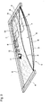
Fig. 1 is a cross-sectional view illustrating the pneumatic panel structure according to one embodiment of the enclosure structure for a building of the present invention. -
Fig. 2 is a perspective view illustratingFig. 1 partly in section. -
Fig. 3 is a perspective view illustrating the whole of a building ofFig. 1 . -
Fig. 4 is a perspective view of the whole of a building, illustrating a modification of the above one embodiment. -
Fig. 5 is a cross-sectional view illustrating the structure of a pneumatic panel according to another embodiment of the present invention. -
- 1:
- Pneumatic panel
- 2:
- Outer film material
- 3:
- Inner film material
- 5:
- Inner space
- 6:
- Intermediate film material
- 6a:
- Opening
- 7:
- Solar battery module
- 8:
- Battery
- 11:
- Fan (air supply means)
- C:
- Building
-
Figs. 1 to 3 illustrate one embodiment wherein the enclosure structure for a building of the present invention is applied to a roof structure of a building, andFig. 4 illustrates its modification. - In these Figs., the roof structure of a building C is schematically constituted by providing a plurality of
solar battery modules 7 inside apneumatic panel 1. - That is, the
pneumatic panel 1 comprises anouter film material 2 and aninner film material 3 formed in two rectangle sheets, each made of a transparent plastic film material such as an ethylene/tetrafluoroethylene copolymer (hereinafter referred to as ETFE), air-tightly integrated along the respective peripheries, and held by aperipheral frame 4. As a result, aninner space 5 is created between theouter film material 2 and theinner film material 3. Further, the roof of the building C is constituted by a plurality of suchpneumatic panels 1 supported by theperipheral frame 4 in such a manner that the respectiveouter film materials 2 are declined facing the sun on the outer surface side of the building C and theinner film materials 3 are arranged facing the inside of the building C, and suchperipheral frames 4 being connected with and supported by a beam/column structure F of the building C. - Further, the
pneumatic panel 1 has anintermediate film material 6 disposed between theouter film material 2 and theinner film material 3. Theintermediate film material 6 is made of a transparent plastic film material such as ETFE in the same manner as theouter film material 2 and theinner film material 3 as is formed into a shape such that the sag is somewhat smaller than that of theinner film material 3, and its periphery is sandwiched between peripheries of theouter film material 2 and theinner film material 3 and integrated therewith. Further, theintermediate film material 6 has anopening 6a formed to communicate the upper space between it and theouter film material 2 with the lower space between it and theinner film material 3. - Further, on the upper surface of the
intermediate film material 6, a plurality (among them, only two sheets are exemplified inFig. 2 ) ofsolar battery modules 7 are attached with a predetermined space one another. Thesolar battery modules 7 are battery modules using an amorphous silicon solar battery and are attached to theintermediate film material 6 with their light receiving cell surface facing upward. - Further, the above plurality of the
solar battery modules 7 can be arranged optionally, and in the building C according to the present embodiment, they are arranged in a checkerboard pattern over the entire surface of the roof as illustrated inFig. 3 . Therefore, between thesolar battery modules 7, the sunlight can enter the building C through theouter film material 2, theintermediate film material 6 and theinner film material 3. - On the other hand, a
battery 8 is provided under theperipheral frame 4 of thepneumatic panel 1.Electric wires 9 connected to the output sides of the respectivesolar battery modules 7 attached to theintermediate film material 6 are drawn toward theperipheral frame 4 side in thepneumatic panel 1, and then, become an assembledline 10 to be connected to the input side of thebattery 8. Thus, the electric power generated by the power generation by thesolar battery modules 7 is input and stored in thebattery 8. - Further, under the
peripheral frame 4, a fan (air supply means) 11 supplying air (gas) to between theinner film material 3 and theintermediate film material 6 in thepneumatic panel 1, and atimer 12 maintaining the internal pressure of thepneumatic panel 1 at a predetermined range by supplying the electric power stored in thebattery 8 to thefan 11 by on-off control at predetermined time intervals interlocked with the decrease speed of the internal pressure in thepneumatic panel 1, are provided adjacent to each other. - According to the roof structure of the building C with the above constitution, since the
solar battery modules 7 are provided on the upper surface of theintermediate film material 6 in thepneumatic panel 1 where the strain by e.g. a change of an external force or an internal pressure rarely occurs, it is possible to maintain the shapes of thesolar battery modules 7 in a stable state. Further, as illustrated inFig. 1 , a part of the sunlight which has reached the roof is transmitted through the light transmittingouter film material 2 and applied to the surface of thesolar battery modules 7 to generate power. - Therefore, it is possible to form a lightweight roof capable of photovoltaic generation, and since the
outer film material 2, theinner film material 3 and theintermediate film material 6 in this roof structure are all made of a light transmitting material, the sunlight transmitted between thesolar battery modules 7 can enter a building. - Besides, in the roof structure, since the whole of the
solar battery modules 7 are provided inside thepneumatic panel 1, no external force will be applied to thesolar battery modules 7, whereby it is possible to maintain a high power generation efficiency for a long period of time, and since no protrusion will be formed on the outer surface of theouter film material 2 and theinner film material 3, unlike a conventional one, dust or the like will not collect, so that no reduction in the power generation efficiency nor obstacle to snow slipping in a snow season will occur. - Further, the periphery of the
intermediate film material 6 is sandwiched between the peripheries of theouter film material 2 and theinner film material 3 and is integrated therewith, and theopening 6a is arranged on theintermediate film material 6 to provide communication between theouter film material 2 and theinner film material 3. Therefore, it is possible to form thepneumatic panel 1 by uniformly pressurizing the whole of inside without theintermediate film material 6 being an obstacle by supplying a gas inside from between theintermediate film material 6 and theinner film material 3, and furthermore, it is also possible to maintain thesolar battery modules 7 stably by stabilizing the posture of theintermediate film material 6. - However, the
pneumatic panel 1 may be formed by using theintermediate film material 6 without theopening 6a, and supplying a gas separately to the space between theouter film material 2 and theintermediate film material 6 and the space between theinner film material 3 and theintermediate film material 6 for pressurization. - Further, since battery modules using an amorphous silicon solar battery excellent in flexibility are used as the
solar battery modules 7, even when theintermediate film material 6 sags, no cracks will occur and a high voltage will be obtained as compared with one using a crystal silicon solar battery. Besides, even when the internal temperature of thepneumatic panel 1 is increased by the sunlight, it is possible to obtain a power generation efficiency higher by about 10% than solar battery modules using other crystal silicon solar battery. - Further, in this roof structure, the output obtained by the power generation by the
solar battery modules 7 is stored in thebattery 8 and is used as a drive resource for thefan 11 which is to maintain the internal pressure of thepneumatic panel 1 constant. Therefore, it is possible to constitute a roof structure using a self-support pneumatic panel which requires no power supply from outside. -
Fig. 4 illustrates a modification of the above embodiment. - This roof structure is different from one illustrated in
Fig. 3 in thatsolar battery modules 7 are intensively arranged on anintermediate film material 6 inside apneumatic panel 1 located at the upper part of a declined roof of a building C, and no solar battery modules are arranged inside thepneumatic panel 1 located at the lower part. - According to the roof structure of the above constitution, since the
solar battery modules 7 are intensively arranged at the upper part of the declined roof, as illustrated by broken line arrows in Fig., the position of a shadow created by the sunlight being shut off by thesesolar battery modules 7 is formed on the wall surface of the building C. Therefore, even when the above roof structure is applied to a building C which requires sufficient sunlight even on the floor, such as an atrium, a horticultural greenhouse or a pool, such an effect can be obtained that shutting off the sunlight by thesolar battery modules 7 is not problematic. - Here, the above embodiment has been explained only with reference to a case where the enclosure structure of a building according to the present invention is applied to a roof structure of a building. However, the present invention is by no means limited thereto, and it is also applicable to other enclosure structures such as a wall in the same manner.
- Further, the above embodiment has been explained only with reference to a case where the
intermediate film material 6 is provided between theouter film material 2 and theinner film material 3, and thesolar battery modules 7 are attached on the upper surface of theintermediate film material 6. However, the present invention is by no means limited thereto, and for example, as illustrated inFig. 5 , it is also possible to constitute apneumatic panel 20 only with anouter film material 2 and aninner film material 3 and to providesolar battery modules 7 on the upper surface of theinner film material 3. - Further, the above embodiment has been explained only with reference to a case where the
outer film material 2 and theinner film material 3 are air-tightly integrated along the respective peripheries. However, the present invention is by no means limited thereto, and theouter film material 2 and theinner film material 3 may be air-tightly sealed along the respective peripheries by, for example, aperipheral frame 4 or the like. - Further, the above embodiment has been explained only with reference to a case where the
solar battery modules 7 using an amorphous silicon solar battery which is thin and excellent in flexibility, are provided on theintermediate film material 6 as the most preferable embodiment. However, the present invention is by no means limited thereto, and since particularly theintermediate film material 6 is rarely affected by the strain caused by a change of an external force or an internal pressure, unlike theouter film material 2 and theinner film material 3, it is also possible to provide solar battery modules using a crystal silicon solar battery. - The present invention provides an enclosure structure useful for various buildings such as an atrium and a greenhouse, which have a power generation function by the sunlight.
- The entire disclosure of Japanese Patent Application No.
2007-335655 filed on December 27, 2007
Claims (8)
- An enclosure structure for a building, comprising an outer film material made of a light transmitting material and arranged on the outer surface side of the building, an inner film material arranged along inside of the outer film material, an air supply means for supplying air to the space between the outer film material and the inner film material, and solar battery modules provided on the inner surface of the inner film material.
- An enclosure structure for a building, comprising an outer film material made of a light transmitting material and arranged on the outer surface side of the building, an inner film material arranged along inside of the outer film material, an intermediate film material disposed between the outer film material and the inner film material, an air supply means for supplying air to the space between the outer film material and the inner film material, and solar battery modules provided on the surface of the intermediate film material facing the outer film material.
- The enclosure structure for a building according to Claim 2, wherein the intermediate film material has an opening and is disposed in a state to provide communication between the outer film material and the inner film material.
- The enclosure structure for a building according to any one of Claims 1 to 3, wherein the inner film material is air-tightly integrated along the periphery with the outer film material.
- The enclosure structure for a building according to any one of Claims 1 to 4, wherein the solar battery modules have flexibility.
- The enclosure structure for a building according to any one of Claims 1 to 5, wherein the solar battery modules are battery modules using an amorphous silicon solar battery.
- The enclosure structure for a building according to any one of Claims 1 to 6, wherein the output sides of the solar battery modules are connected to a battery, and at least a part of the electric power stored by the battery is supplied as a drive resource for the air supply means.
- The enclosure structure for a building according to any one of Claims 1 to 7, wherein the solar battery modules are arranged with a space one another so that the sunlight is transmitted between the solar battery modules.
Applications Claiming Priority (2)
| Application Number | Priority Date | Filing Date | Title |
|---|---|---|---|
| JP2007335655 | 2007-12-27 | ||
| PCT/JP2008/073831 WO2009084672A1 (en) | 2007-12-27 | 2008-12-26 | Enclosure structure of building |
Publications (2)
| Publication Number | Publication Date |
|---|---|
| EP2233666A1 true EP2233666A1 (en) | 2010-09-29 |
| EP2233666A4 EP2233666A4 (en) | 2013-12-18 |
Family
ID=40824385
Family Applications (1)
| Application Number | Title | Priority Date | Filing Date |
|---|---|---|---|
| EP08868125.9A Withdrawn EP2233666A4 (en) | 2007-12-27 | 2008-12-26 | BUILDING ENCLOSURE STRUCTURE |
Country Status (5)
| Country | Link |
|---|---|
| US (1) | US8146296B2 (en) |
| EP (1) | EP2233666A4 (en) |
| JP (1) | JP5003670B2 (en) |
| CN (1) | CN101910532B (en) |
| WO (1) | WO2009084672A1 (en) |
Cited By (1)
| Publication number | Priority date | Publication date | Assignee | Title |
|---|---|---|---|---|
| WO2011073448A3 (en) * | 2009-12-18 | 2012-05-03 | Seele Holding Gmbh & Co. Kg | Membrane building component with a solar panel |
Families Citing this family (25)
| Publication number | Priority date | Publication date | Assignee | Title |
|---|---|---|---|---|
| US20080283112A1 (en) * | 2003-04-02 | 2008-11-20 | Conger Steven J | Solar array support methods and systems |
| US8381464B2 (en) * | 2003-04-02 | 2013-02-26 | P4P Holdings Llc | Solar array support methods and systems |
| US8429861B2 (en) * | 2003-04-02 | 2013-04-30 | P4P Holdings Llc | Solar array support methods and systems |
| US9564851B2 (en) | 2003-04-02 | 2017-02-07 | P4P Holdings, LLC | Solar array support methods and systems |
| US8875450B2 (en) | 2003-04-02 | 2014-11-04 | P4P Holdings, LLC | Solar array system for covering a body of water |
| US8212140B2 (en) | 2003-04-02 | 2012-07-03 | P4P, Llc | Solar array support methods and systems |
| US8278547B2 (en) * | 2003-04-02 | 2012-10-02 | P4P Holdings Llc | Solar array support methods and systems |
| US20100314509A1 (en) | 2003-04-02 | 2010-12-16 | Conger Steven J | Solar array support methods and systems |
| US7285719B2 (en) | 2003-04-02 | 2007-10-23 | Solar Suspension Systems, Llc | Solar array support methods and systems |
| USD605585S1 (en) | 2003-06-25 | 2009-12-08 | Solar Suspension Systems, Llc | Solar array |
| USD649112S1 (en) | 2003-06-25 | 2011-11-22 | P4P Holdings, LLC | Solar array |
| KR100954727B1 (en) * | 2009-10-19 | 2010-04-23 | (주) 스위텍 | Translucent pannel |
| US20120031488A1 (en) * | 2010-08-06 | 2012-02-09 | Wattlots Llc | Photovoltaic cell module assembly |
| USD664916S1 (en) | 2011-06-21 | 2012-08-07 | P4P Holdings, LLC | Solar array |
| USD679242S1 (en) | 2011-12-06 | 2013-04-02 | P4P Holdings, LLC | Solar array |
| FR3004004B1 (en) * | 2013-03-29 | 2016-08-12 | Soitec Silicon On Insulator | METHOD FOR ASSEMBLING PHOTOVOLTAIC CELLS WITH MULTIPLE TRANSFER |
| KR101429109B1 (en) | 2013-06-27 | 2014-08-13 | 협성대학교산학협력단 | Double layered membrane structures with cushion system |
| KR101429119B1 (en) * | 2014-05-23 | 2014-08-13 | 협성대학교산학협력단 | Double layered membrane structures with cushion system |
| US20180050784A1 (en) * | 2015-03-10 | 2018-02-22 | Antoine Marcel PAULUS | Mobile artificial cloud |
| CN104763052B (en) * | 2015-03-25 | 2016-10-05 | 东南大学 | A foldable and unfolded cable-membrane truss structure |
| KR101715679B1 (en) * | 2016-09-28 | 2017-03-13 | 주식회사 에이원스페이스 | Membrane structures of using reinforced built-up beam and dual air cushion |
| KR101715680B1 (en) * | 2016-09-28 | 2017-03-13 | 주식회사 에이원스페이스 | Prefabricated building structures with built-up beam and air panel |
| DE102017129059A1 (en) * | 2017-12-06 | 2019-06-06 | Vector Foiltec Gmbh | Device for discharging a liquid and building envelope elements with such a device |
| US11686097B2 (en) * | 2019-11-22 | 2023-06-27 | Arizona Board Of Regents On Behalf Of Arizona State University | Skylights with integrated photovoltaics and refractive light-steering |
| WO2026049612A1 (en) * | 2024-08-29 | 2026-03-05 | Taylor’s University Sdn Bhd | Assembly for variably regulating light transmission between building indoor and outdoor spaces to achieve tunable shading, method and system thereof |
Family Cites Families (35)
| Publication number | Priority date | Publication date | Assignee | Title |
|---|---|---|---|---|
| US3375136A (en) * | 1965-05-24 | 1968-03-26 | Army Usa | Laminated thin film flexible alkaline battery |
| US3658596A (en) * | 1970-09-21 | 1972-04-25 | Lockheed Missiles Space | Flexible solar cell modular assembly |
| US3908631A (en) * | 1974-03-12 | 1975-09-30 | Frank E Rom | Method and apparatus for converting solar radiation to heat energy |
| US4057439A (en) * | 1976-08-25 | 1977-11-08 | Solarex Corporation | Solar panel |
| US4182307A (en) * | 1977-07-21 | 1980-01-08 | Donald Shanfelt | Inflatable solar energy collector |
| US4262457A (en) * | 1978-09-12 | 1981-04-21 | Darmstadt Robert M | Pneumatic structures |
| US4258697A (en) * | 1979-03-15 | 1981-03-31 | Flagg Rodger H | Pneumatic collection, storage and transfer of solar heat |
| ES8100843A1 (en) * | 1979-05-08 | 1980-12-16 | Saint Gobain Vitrage | Method of manufacturing solar-cell panels and panels obtained by this method. |
| FR2461901A1 (en) * | 1979-07-19 | 1981-02-06 | Rhone Poulenc Ind | SOLAR ENERGY SENSOR, WATER HEATER AND HEATING DEVICE WITH HEAT PUMP COMPRISING SAID SENSOR |
| US4321912A (en) * | 1980-07-11 | 1982-03-30 | Larsen Raymond B | Solar energy collector assembly and frame |
| US4485804A (en) * | 1981-01-30 | 1984-12-04 | T. E. Sharpe | Solar heat collector system |
| US4390010A (en) * | 1981-03-12 | 1983-06-28 | Skillman Dale N | Solar energy collecting apparatus and roll-formed metal building |
| US5027564A (en) * | 1988-05-09 | 1991-07-02 | Colux Gesellschaft fur Licht - und Leichtbau mbH | Building construction with a chamber which can be acted upon by a fluid medium |
| JPH022849U (en) * | 1988-06-20 | 1990-01-10 | ||
| JP2557809B2 (en) * | 1989-12-04 | 1996-11-27 | 株式会社フジタ | Air dome equipped with solar cells |
| JPH05221387A (en) * | 1992-02-13 | 1993-08-31 | Sanyo Electric Co Ltd | Airship with solar battery |
| DE4240616A1 (en) * | 1992-12-03 | 1994-06-09 | Westsolar Gmbh | Solar cell arrangement |
| US5505788A (en) * | 1994-06-29 | 1996-04-09 | Dinwoodie; Thomas L. | Thermally regulated photovoltaic roofing assembly |
| JP3759799B2 (en) * | 1996-08-30 | 2006-03-29 | 大和ハウス工業株式会社 | Joint between outer panel of corner of dome-shaped building |
| JPH1146007A (en) | 1997-07-26 | 1999-02-16 | Taiyo Kogyo Kk | Solar battery mounting structure |
| US6224016B1 (en) * | 1997-12-19 | 2001-05-01 | Sky Station International, Inc. | Integrated flexible solar cell material and method of production |
| US6295663B1 (en) * | 1998-06-30 | 2001-10-02 | Stearns Inc. | Pressurized solar heated shower |
| DE19982011D2 (en) * | 1998-10-05 | 2001-09-27 | Powerpulse Holding Ag Zug | Light element with a translucent surface |
| DE19950500C2 (en) * | 1999-10-20 | 2001-12-20 | Uwe Rudolf Brueckner | Double-walled film field, in particular film wall segment |
| JP2001291888A (en) * | 2000-04-10 | 2001-10-19 | Tdk Corp | Photovoltaic generator and attaching method thereof |
| GB2387183B (en) * | 2002-04-02 | 2005-07-27 | Vector Special Projects Ltd | Building component |
| GB2387395B (en) * | 2002-04-12 | 2005-08-24 | Benedict George Morris | Liquid retaining cushion roof element |
| CN2642033Y (en) * | 2003-10-13 | 2004-09-22 | 中国农业科学院农业气象研究所 | Lighting device suitable to daylight greenhouse |
| US7303166B2 (en) * | 2003-11-04 | 2007-12-04 | Daniel Geery | Highly maneuverable powered airship |
| DE102005048403A1 (en) * | 2005-10-10 | 2007-04-12 | Verena Herzog-Loibl | Pneumatically stabilized cover for a building |
| US20070234945A1 (en) * | 2005-11-28 | 2007-10-11 | Khouri Bruce M | Photovoltaic floatation device |
| DE202007015754U1 (en) * | 2007-11-09 | 2009-03-26 | Vector Foiltec Gmbh | Foil cushion arrangement |
| US7849635B2 (en) * | 2009-01-23 | 2010-12-14 | Vector Foiltec | Building encasement element |
| JP2011045525A (en) * | 2009-08-27 | 2011-03-10 | Fujifilm Corp | Endoscope |
| US8438797B2 (en) * | 2009-12-25 | 2013-05-14 | Institute Of Nuclear Energy Research, Atomic Energy Council, Executive Yuan | Outer frame drainage structure of concentrator type solar cell module |
-
2008
- 2008-12-25 JP JP2008329717A patent/JP5003670B2/en not_active Expired - Fee Related
- 2008-12-26 CN CN200880123199XA patent/CN101910532B/en not_active Expired - Fee Related
- 2008-12-26 EP EP08868125.9A patent/EP2233666A4/en not_active Withdrawn
- 2008-12-26 WO PCT/JP2008/073831 patent/WO2009084672A1/en not_active Ceased
-
2010
- 2010-06-17 US US12/817,257 patent/US8146296B2/en not_active Expired - Fee Related
Cited By (1)
| Publication number | Priority date | Publication date | Assignee | Title |
|---|---|---|---|---|
| WO2011073448A3 (en) * | 2009-12-18 | 2012-05-03 | Seele Holding Gmbh & Co. Kg | Membrane building component with a solar panel |
Also Published As
| Publication number | Publication date |
|---|---|
| JP5003670B2 (en) | 2012-08-15 |
| CN101910532A (en) | 2010-12-08 |
| US20100251618A1 (en) | 2010-10-07 |
| US8146296B2 (en) | 2012-04-03 |
| CN101910532B (en) | 2012-12-26 |
| WO2009084672A1 (en) | 2009-07-09 |
| EP2233666A4 (en) | 2013-12-18 |
| JP2009177163A (en) | 2009-08-06 |
Similar Documents
| Publication | Publication Date | Title |
|---|---|---|
| US8146296B2 (en) | Enclosure structure for building | |
| US20080034684A1 (en) | Building component | |
| US20110277809A1 (en) | Modular Tensile Structure with Integrated Photovoltaic Modules | |
| CN109415111B (en) | Floating plate, floating plate assembly and method for installing floating plate assembly | |
| US20190288639A1 (en) | Systems and methods for applying flexible solar panels to flexible underlying membranes | |
| US10381498B2 (en) | Flexible laminates for solar modules | |
| JPWO2009107776A1 (en) | Solar power system | |
| WO2011090160A1 (en) | Solar cell module | |
| CN114175499B (en) | Solar panels | |
| JP2011187657A (en) | Solar cell module and method of reinforcing solar cell module | |
| JP2005317588A (en) | Solar power plant | |
| JP2022082923A (en) | Solar battery panel | |
| KR102771733B1 (en) | Connection Plate-Integrated Solar Cell Module And Laminating Method For Solar Cell Module | |
| JP6993091B2 (en) | Construction structure of solar cell sheet | |
| EP3408868B1 (en) | Arrangements of flexible photovoltaic modules | |
| EP3710760B1 (en) | Actuator, mechanism comprising the actuator, solar energy harnessing apparatus, arrangement of buildings, and a method for manufacturing the actuator | |
| JP4412087B2 (en) | Waterproof sheet solar panel set, construction method and construction structure | |
| DE202009017110U1 (en) | Membranbaukomponente | |
| JP2013062453A (en) | Flexible solar cell module and fixing mechanism of the same | |
| JP2007180314A (en) | Solar cell module | |
| CN211369177U (en) | Photovoltaic curtain wall system and structure-reinforced photovoltaic curtain wall module | |
| JP7858944B2 (en) | Solar cell structure and method for installing solar cells | |
| IT201600107594A1 (en) | Photovoltaic panel having a flexible structure and relative manufacturing method. | |
| JP3245695U (en) | Solar power sheet installation stand | |
| JP2011151278A (en) | Photovoltaic power generation system |
Legal Events
| Date | Code | Title | Description |
|---|---|---|---|
| PUAI | Public reference made under article 153(3) epc to a published international application that has entered the european phase |
Free format text: ORIGINAL CODE: 0009012 |
|
| 17P | Request for examination filed |
Effective date: 20100610 |
|
| AK | Designated contracting states |
Kind code of ref document: A1 Designated state(s): AT BE BG CH CY CZ DE DK EE ES FI FR GB GR HR HU IE IS IT LI LT LU LV MC MT NL NO PL PT RO SE SI SK TR |
|
| AX | Request for extension of the european patent |
Extension state: AL BA MK RS |
|
| DAX | Request for extension of the european patent (deleted) | ||
| RAP1 | Party data changed (applicant data changed or rights of an application transferred) |
Owner name: ASAHI GLASS COMPANY, LIMITED |
|
| A4 | Supplementary search report drawn up and despatched |
Effective date: 20131119 |
|
| RIC1 | Information provided on ipc code assigned before grant |
Ipc: H01L 31/042 20060101ALI20131113BHEP Ipc: E04D 13/18 20060101ALI20131113BHEP Ipc: E04H 15/20 20060101AFI20131113BHEP |
|
| 17Q | First examination report despatched |
Effective date: 20150223 |
|
| STAA | Information on the status of an ep patent application or granted ep patent |
Free format text: STATUS: THE APPLICATION IS DEEMED TO BE WITHDRAWN |
|
| 18D | Application deemed to be withdrawn |
Effective date: 20160225 |