EP2233629A2 - Multi-needle sewing machine - Google Patents
Multi-needle sewing machine Download PDFInfo
- Publication number
- EP2233629A2 EP2233629A2 EP10156094A EP10156094A EP2233629A2 EP 2233629 A2 EP2233629 A2 EP 2233629A2 EP 10156094 A EP10156094 A EP 10156094A EP 10156094 A EP10156094 A EP 10156094A EP 2233629 A2 EP2233629 A2 EP 2233629A2
- Authority
- EP
- European Patent Office
- Prior art keywords
- thread guide
- thread
- machine frame
- needle
- frame side
- Prior art date
- Legal status (The legal status is an assumption and is not a legal conclusion. Google has not performed a legal analysis and makes no representation as to the accuracy of the status listed.)
- Withdrawn
Links
Images







Classifications
-
- D—TEXTILES; PAPER
- D05—SEWING; EMBROIDERING; TUFTING
- D05C—EMBROIDERING; TUFTING
- D05C11/00—Devices for guiding, feeding, handling, or treating the threads in embroidering machines; Machine needles; Operating or control mechanisms therefor
- D05C11/16—Arrangements for repeating thread patterns or for changing threads
-
- D—TEXTILES; PAPER
- D05—SEWING; EMBROIDERING; TUFTING
- D05C—EMBROIDERING; TUFTING
- D05C3/00—General types of embroidering machines
- D05C3/02—General types of embroidering machines with vertical needles
Definitions
- the present invention relates to a multi-needle sewing machine provided with a needle-bar moving mechanism which moves a needle bar case housing a plurality of needle bars.
- Multi-needle sewing machines have conventionally been used to sew an embroidery pattern of a plurality of colors.
- the multi-needle sewing machine is generally provided with needle bar case in which are housed a plurality of needle bars having lower ends to which needles are attached respectively. The needle bar case is moved in a right-left direction so that one of the plural needle bars is selected. Threads are supplied from thread spools to the needles respectively.
- the conventional multi-needle sewing machines have a possibility that the movement of the needle bar case may entangle the needles drawn from the plural thread spools with each other or one another.
- the multi-needle embroidery sewing machines disclosed by the respective above-referenced first and second documents employ the construction that the needle bar case and a spool holder on which thread spools are placed are moved synchronously.
- this countermeasure complicates the construction of the multi-needle sewing machine and increases the size of the multi-needle sewing machine.
- the third document discloses a spool holder device for an embroidery sewing machine, wherein threads are passed through a plurality of elongate tubes respectively so that the threads are prevented from interference with each other or one another. Passing the threads through the respective tubes has a difficulty.
- an object of the invention is to provide a multi-needle sewing machine which has a simple construction and is compact in size and can prevent thread entanglement without a troublesome work of passing the threads through tubes.
- the present invention provides a multi-needle sewing machine which comprises a plurality of needle bars having lower ends to which needles are attached, respectively; a needle bar case which supports the needles so that the needles are movable upward and downward; and a needle bar case moving mechanism which moves the needle bar case so that a predetermined one of the needle bars is moved to a needle position that is a sewing position, characterized by a machine frame side thread guide member which is fixed to a machine frame and has a plurality of machine frame side thread guide portions which are arranged at predetermined intervals and guide threads drawn from a plurality of thread spools provided on the machine frame respectively; a plurality of thread entrances which are defined in the needle bar case to introduce the threads guided by the machine frame side thread guide portions to the needle sides of the needle bars, respectively; a plurality of intermediate thread guide portions which are provided between the machine frame side thread guide portions and the thread entrances so as to be movable respectively, the intermediate thread guide portions guiding intermediate portions of the threads extending from the machine frame
- FIGS. 1 to 22 A first embodiment will be described with reference to FIGS. 1 to 22 .
- the side of a multi-needle sewing machine M where the user or operator is located is referred to as "front.”
- the multi-needle sewing machine M includes a pair of right and left legs 1 supporting the overall sewing machine, a pillar 2 standing on rear ends of the legs 1, an arm 3 extending frontward from an upper part of the pillar 2, a cylinder bed 4 extending frontward from a rear end of the pillar 2, and a needle bar case 5 mounted on a front end of the arm 3.
- the legs 1, pillar 2, arm 3 and cylinder bed 4 are formed integrally with one another into a sewing machine body 7.
- a control device (not shown) controlling the overall multi-needle sewing machine M, an operation panel 6 and the like are provided at the sewing machine body 7 side.
- a needle plate 4a is mounted on an upper surface of the cylinder bed 4.
- the needle plate 4a is formed with a needle hole (not shown) serving as a needle position for needles 10a to 10f as will be described later.
- a carriage 8 directed in the right-left direction is disposed above the legs 1.
- An X-direction drive mechanism (not shown) is provided inside the carriage 8 to drive a frame mounting (not shown) in the X direction (the right-left direction).
- a Y-direction drive mechanism is provided inside the legs 1 to drive the carriage 8 in the Y direction (the front-back direction).
- the frame mounting is located in front of the carriage 8.
- a generally rectangular embroidery frame (not shown) holds a workpiece cloth on which embroidery is to be sewn.
- the embroidery frame is to be mounted on the frame mounting.
- the carriage 8 is driven in the Y direction by the Y-direction drive mechanism, and the frame mounting is driven in the X direction by the X-direction drive mechanism as described above. Accordingly, the embroidery frame is moved in the Y direction in synchronization with the carriage 8 and in the X direction with the frame mounting, whereby the workpiece cloth is fed.
- Six needle bars 9a to 9f are arranged in the right-left direction so as to extend in the up-down direction in the needle bar case 5 and supported so as to be movable upward and downward.
- Six needles 10a to 10f are attached to lower ends of the needle bars 9a-9f respectively.
- Six thread take-up levers 11 corresponding to the respective needle bars 9a-9f are also provided in the needle bar case 5 so as to be movable upward and downward.
- a cover 5a made of a synthetic resin is mounted on a front side of the needle bar case 5.
- a thread tension bracket 12 inclined forwardly downward is mounted on the upper surface of the needle bar case 5 so as to be continuous to the upper end of the cover 5a.
- Six cylindrical members 13A to 13F are aligned on a rear end of the thread tension bracket 12 in the right-left direction as shown in FIGS. 6 and 7 .
- the cylindrical members 13A-13F have hollow interiors serving as thread entrances 13a to 13f respectively.
- Six auxiliary thread guide portions 14a to 14f are provided on the front sides of the thread entrances 13a-13f respectively.
- Six thread tensioners 15a to 15f are mounted on the thread tension bracket 12 to adjust tensions of upper threads supplied to the needles 10a-10f respectively.
- a needle bar case moving mechanism 16 moves the needle bar case 5 in the right-left direction so that a predetermined one of the six needle bars 9a-9f is moved to the needle position that is a sewing position.
- the needle bar case moving mechanism 16 includes a guide rail 17, six roller bearings 18, a spiral cam 19, a reduction gear assembly 20 and a needle bar case moving motor 21.
- the guide rail 17 is mounted on the front end of the arm 3 so as to extend in the right-left direction.
- the needle-case 5 is supported on the guide rail 17 so as to be slid along the guide rail 17.
- the needle bar case 5 has an upper rear end protruding toward an upper surface of the front end of the arm 3.
- the roller bearings 18 are aligned on the upper rear end of the needle bar case 5 in the right-left direction.
- the roller bearings 18 have the same pitch as the needle bars 9a-9f and are pivotally mounted on respective shafts 18a protruding rearward.
- the spiral cam 19 is coupled with a shaft 19a on the upper surface of the arm 3 so as to be rotatable with it.
- the shaft 19a is directed in the right-left direction.
- Rotation of the needle bar case moving motor 21 is transmitted via the reduction gear 20 to the shaft 19a.
- the reduction gear 20 is mounted on the upper surface of the arm 3.
- the spiral cam 19 is formed with a spiral groove 19b into which each roller bearing 18 is fittable. Thus, at least one of the roller bearings 18 is fitted in the spiral groove 19b.
- the spiral cam 19 is rotated in a predetermined direction upon rotation of the needle bar case moving motor 21 in a predetermined direction.
- the aforesaid roller bearings 18 receive a rightward moving force from the spiral groove 19b such that the needle bar case 5 is moved rightward.
- the needle bar case 5 is moved leftward when the motor 21 is rotated in the direction opposite the aforesaid predetermined direction.
- one of six sets of the needle bars 9a-9f and the thread take-up lever 11 is selectively changed to the needle position.
- the selected one set is moved upward and downward in synchronization with drive of a sewing machine motor (not shown) provided in the pillar 2.
- one set of the needle bar and the thread take-up lever 11 forms embroidery stitches on the workpiece cloth held on the embroidery frame in cooperation with a rotary hook (not shown) mounted on the front end of the cylinder bed 4.
- a spool holder base 22 is mounted on a fixed frame 3a corresponding to the machine frame mounted on the arm 3 of the sewing machine body 7.
- Six spool pins 22a stand on the spool holder base 22 so as to be aligned in the right-left direction.
- Six thread spools 23a to 23f are attached to the spool pins 22a respectively.
- a thread holding member 24 is provided on a front of the fixed frame 3a and includes a support holder 25a, a support 25, a passing member 26, a thread hooking member 27 and a machine frame side thread guide member 28.
- the support holder 25a is formed into a generally long cylindrical shape in a planar view and fixed to a front right part of the fixed frame 3a (a part protruding from the arm 3) by screws 25b so as to stand on the fixed frame 3a.
- a support insertion hole 3b is formed in the front right part of the fixed frame 3a and is slightly larger than a hollow interior of the support holder 25a in a planar view as shown in FIG. 10 .
- the support 25 has a lower end that is inserted into the support holder 25a and fixed by a screw 25c.
- the passing member 26 is fixed to an upper end of the support 25 by a screw 26a so as to be directed in the front-back direction.
- the thread hooking member 27 is fixed to a rear end of the passing member 26 by a screw 27g so as to be directed in the right-left direction.
- the thread hooking member 27 has six threading holes (see FIG. 4 ) which are formed therein so as to be located substantially right above the respective spool pins 22a.
- the machine frame side thread guide member 28 is fixed to a front end of the passing member 26 so as to be directed in the right-left direction.
- the machine frame side thread guide member 28 has three elongate plate members 28a, 28b and 28c stacked one upon another as shown in FIGS. 11 to 18 .
- the plate members 28a and 28b are spaced from each other so that a thread is allowed to pass therebetween in a curved state, as will be described in detail later.
- the plate members 28b and 28c are also spaced from each other so that a thread is allowed to pass therebetween in a curved state.
- Both outer plate members 28a and 28c are fixed by a spacer 28d (see FIG. 13 ) and a screw 28e so that a space allowing movement of the intermediate plate member 28b is defined therebetween.
- the machine frame side thread guide member 28 is provided with six machine frame side thread guide portions 29a to 29f including six outer thread insertion holes 30a to 30f formed in one outer plate member 28a, six outer thread insertion holes 32a to 32f formed in the other outer plate member 28c, and six inner thread insertion holes 31a to 31f formed in the intermediate plate member 28b.
- the outer thread insertion holes 30a-30f are formed substantially at regular intervals in the outer plate member 28a.
- the outer thread insertion holes 32a-32f are also formed substantially at regular intervals in the other outer plate member 28c so as to correspond to the outer thread insertion holes 30a-30f respectively in a front view.
- the outer thread insertions holes 30a-30f and 32a-32f have upper portions open at upper ends of the plate members 28a and 28c respectively.
- the inner thread insertion holes 31a-31f are formed in the intermediate plate member 28b and have the same intervals as the outer thread insertion holes 30a-30f and 32a-32f.
- the inner thread insertion holes 31a-31f also have upper portions open at upper ends of the intermediate plate member 28b respectively.
- the intermediate plate member 28b has a left end formed with a guide groove 33 (see FIG. 17 ) which is directed in the right-left direction and comprises an elongate hole.
- the plate member 28b has a right end formed with a guide groove 34 comprising an upwardly directed hole 34a and a horizontally directed elongate hole 34b both of which are continuous to each other.
- Two guide pins 35 and 36 mounted on the outer plate members 28a and 28c are inserted through the guide grooves 33 and 34 respectively.
- the intermediate plate member 28b is switchable between a use position (a position during sewing) as shown in FIG. 17 and a threading position as shown in FIG. 18 .
- the guide pin 36 is fitted in the upward hole 34a of the guide groove 34 thereby to prevent the intermediate plate member 28b from rightward and leftward movement.
- the inner thread insertion holes 31a-31f are shifted in the right direction relative to the outer thread insertion holes 30a-30f and 32a-32f.
- the locations of the inner thread insertion holes 31a-31f correspond substantially to the locations of the outer thread insertion holes 30a-30f and 32a-32f respectively.
- the outer thread insertion holes 30a-30f and 32a-32f and the inner thread insertion holes 31a-31f constitute the machine frame side thread guides 29a-39f respectively and further constitute curving units 37a-37f respectively.
- the intermediate plate member 28b occupies the threading position as shown in FIG. 18 , the thread can be inserted, from above, through the outer thread insertion holes 30a-30f and 32a-32f and the inner thread insertion holes 31a-31f positionally correspond to one another respectively.
- the intermediate plate member 28b is moved to the use position as shown in FIG.
- the threads are curved by the curving units 37a-37f the inner thread insertion holes 31a-31f are shifted in the right direction relative to the outer thread insertion holes 30a-30f and 32a-32f respectively as shown in FIGS. 15 and 16 .
- the support 25 is movable downward (a retracted position as shown in FIGS. 9 and 10 ) in the support holder 25a and the support insertion hole 3b relative to the support holder 25a by loosening the screw 25c.
- an intermediate thread guide member 38 and an intermediate thread guide moving mechanism 39 both of which will be described later are also retracted as well as the support 25.
- intermediate thread guide portions 38a to 38f are located between the machine frame side thread guide portions 29a to 29f and the thread entrances 13a-13f respectively as shown in FIGS. 1 and 6 .
- the intermediate thread guide portions 38a-38f are provided on the intermediate thread guide member 38 at the same intervals as the machine frame side thread guide portions 29a-29f.
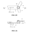
- the intermediate thread guide portions 38a-38f are made by bending metal wire rods generally into a U-shape in a plan view, as shown in FIG. 21 .
- the intermediate thread guide portion moving mechanism 39 moves the intermediate thread guide portions 38a-38f according to movement of the needle bar case 5 when the thread entrances 13a-13f are moved with the movement of the needle bar case 5, as shown in FIGS. 1 to 6 and 19 .
- the intermediate thread guide portion moving mechanism 39 includes a pair of first link members 40 and 41 and a pair of second link members 42 and 43.
- the first link members 40 and 41 are set so as to have the same length (the same link length A), and the second link members 42 and 43 are set so as to have the same length (the same link length B).
- the first link member 40 has one (an upper end as viewed in FIGS. 6 and 19 ) of two ends that is formed with a pivot pin 40a which is mounted on one (a right end as viewed in FIG.
- the first link member 40 has the other end that is formed with a pivot pin 40b which is mounted on one (a right end as viewed in FIG. 6 ) of two ends of the intermediate thread guide member 38 so that the first link member 40 is pivotally movable about the pivot pin 40b in the direction of arrow Ra.
- the other first link member 41 has one (an upper end as viewed in FIGS. 6 and 19 ) of two ends that is formed with a pivot pin 41a which is mounted on the other end (a left end) of the machine frame side thread guide member 28 so that the first link member 41 is pivotally movable about the pivot pin 41a in the direction f arrow Ra.
- the first link member 41 has the other end that is formed with a pivot pin 41b which is mounted on the other end of the intermediate thread guide member 38 so that the first link member 41 is pivotally movable about the pivot pin 41b in the direction of arrow Ra.
- a support piece 44 has a support shaft 44a, and the second link member 42 has one (a lower end as viewed in FIGS. 6 and 19 ) of two ends that is mounted on a support shaft 44a so that the second link member 42 is pivotable in the direction of arrow Ra.
- the support piece 44 is provided near the thread entrance which constitutes one end of the row of thread entrances 13a-13f of the needle bar case 5.
- the second link member 42 has the other end (an upper end as viewed in FIGS. 6 and 19 ) that is mounted on the pin 40b mounted on the aforesaid one end of the intermediate thread guide member 38 so that the second link member 42 is pivotable in the direction of arrow Ra.
- a support piece 45 has a support shaft 45a, and the other second link member 43 has one (a lower end as viewed in FIGS. 6 and 19 ) of two ends that is mounted on the support shaft 45a so that the support piece 45 is pivotable in the direction of arrow Ra.
- the support piece 45 is provided near the thread entrance which constitutes the other end of the row of thread entrances 13a-13f of the needle bar case 5.
- the second link member 43 has the other end that is mounted on the pin 41b mounted on the aforesaid other end of the intermediate thread guide member 38 so that the second link member 43 is pivotable in the direction of arrow Ra.
- Reference symbols I1, I2 and I3 designate a distance between the pins 40a and 41a, a distance between the pins 40b and 41b and a distance between the support shafts 44a and 45a respectively. These distances I1, I2 and I3 are set so as to be equal to one another. Furthermore, the first link members 40 and 41 have the same length A, and the second link members 42 and 43 have the same length B. A parallel link mechanism is constituted by the paired first link members 40 and 41, the paired second link members 42 and 43 and the intermediate thread guide member 38.
- Reference symbols C1, C2 and C3 designate a distance between the pin 41a and the machine frame side thread guide portion 29a, a distance between the pin 41b and the intermediate thread guide portion 38a and a distance between the support shaft 45a and the thread entrance 13a respectively. These distances C1, C2 and C3 are set so as to be equal to one another. Furthermore, reference symbols D1, E1, F1, G1 and H1 designate distances between the machine frame side thread guide portions 29a-29f respectively. Reference symbols D2, E2, F2, G2 and H2 designate distances between the thread entrances 13a-13f corresponding to the distances D1, E1, F1, G1 and H1, respectively. Reference symbols D3, E3, F3, G3 and H3 designate distances between the thread entrances 13a-13f respectively.
- the threads having been introduced into the thread entrances 13a-13f are further passed through auxiliary thread guide portions 14a to 14f, thread tensioners 15a to 15f, thread take-up levers 11 and the like thereafter to be passed through eyes (not shown) of the needles 10a to 10f, respectively.
- the intermediate thread guide portions 38a-38f of the intermediate thread guide member 38 guide the intermediate portions of the threads Ia-If between the machine-frame side thread guide portions 29a-29f serving as a fixed side and the thread entrances 13a-13f serving as a movement side.
- the above-described multi-needle sewing machine will work as follows.
- the needle bar case 5 is moved by the needle-bar moving mechanism 16 so that one of the needle bars 9a-9f occupies the sewing position P (see FIG. 6 ).
- a leftmost movement position is the position (a position shown by solid line in FIGS. 6 and 22 ) where the needle bar 9f corresponds to the sewing position P.
- a rightmost movement position is the position (a position shown by two-dot chain line in FIG. 6 ) where the needle bar 9a corresponds to the sewing position P.
- the thread entrances 13a-13f are also moved in the right-left direction with the movement of the needle bar case 5 in the right-left direction.
- FIG. 22 shows only one thread Ib for the sake of easiness in the explanation of operation of the intermediate thread guide portion moving mechanism 39. However, it is assumed that six threads Ia-If would actually be used.
- the lower ends of the first link members 40 and 41 of the second link members 42 and 43 of the intermediate thread guide portion moving mechanism 39 are also moved with the movement of the needle bar case 5.
- the first and second link members 40, 41 and 42, 43 are curved in the right-left direction.
- the intermediate thread guide member 38 is also moved in the right-left direction.
- the second link members 42 and 43 are swung in parallel to each other, and the first link members 40 and 41 are also swung in parallel to each other.
- the intermediate thread guide member 38 is moved in parallel to the rows of the machine frame side thread guide portions 29a-29f and the thread entrances 13a-13f.
- the intermediate thread guide portions 38a-38f are also moved in parallel to one another while being spaced from one another.
- the intermediate portions of the threads Ia-If between the machine frame side thread guide portions 29a-29f and the thread entrances 13a-13f are guided by the intermediate thread guide portions 38a-38f individually, respectively. Consequently, the threads Ia-If can effectively be prevented from being entangled.
- the intermediate thread guide portion moving mechanism 39 moves the intermediate thread guide portions 38a-38f according to the movement of the needle bar case 5 during the movement of the thread entrances 13a-13f with the movement of the needle bar case 5 while the guide portions 38a-38f are spaced from one another.
- the intermediate thread guide portions 38a-38f are moved between the guide portions 29a-29f and the thread entrances 13a-13f while being spaced from one another. Consequently, the threads Ia-If can be prevented from being entangled with one another, and an occurrence of thread entanglement can reliably be prevented.
- the thread spools 23a-23f are provided on the sewing machine frame (the fixed frame 3a) but not on the needle bar case 5, which construction differs from the construction of conventional multi-needle sewing machines in which the needle bar case 5 and the spool holder base to which the thread spools 23a-23f are attached are moved together. Accordingly, the foregoing construction of the embodiment is simplified and rendered more compact as compared with the conventional construction.
- the multi-needle sewing machine M is constructed so that the intermediate portions of the threads Ia-If are guided through the intermediate thread guide portions 38a-38f. This does not necessitate the troublesome work of passing the threads through the elongate tubes respectively, and the threading work can also be simplified.
- the intermediate thread guide portion moving mechanism 39 is constructed into the parallel link mechanism including the paired first link members 40 and 41, the paired second link members 42 and 43 and the intermediate thread guide portions 38a-38f. Accordingly, the plural intermediate thread guide portions 38a-38f are moved substantially in parallel to the movement direction of the thread entrances 13a-13f. Consequently, an occurrence of thread entanglement can reliably be prevented. Furthermore, when the intermediate thread guide member 38 has been moved by the intermediate thread guide portion moving mechanism 39, the lengths of the threads Ia-If from the machine frame side thread guide portions 29a-29f to the thread entrances 13a-13f are substantially limited to the length (A+B) of addition of the lengths of the first and second link members 40 (41) and 42 (43). As a result, the threads Ia-If can be prevented from being loosened.
- the machine frame side thread guide portions 29a-29f of the machine frame side thread guide member 28 includes the curving units 37a-37f which curve the threads Ia-If respectively. As a result, a slight passage resistance is applied to each of the threads Ia-If, whereby the behavior of each thread can be rendered more stable.
- the machine frame side thread guide member 28 includes three elongate plate members 28a, 28b and 28c which are stacked one upon another.
- the outer plate members 28a and 28c have the outer thread insertion holes 30a-30f and 32a-32f whose positions correspond with one another, respectively.
- the intermediate plate member 28b is formed with the inner thread insertion holes 31a-31f shifted from the outer thread insertion holes 30a-30f and 32a-32f respectively.
- These thread insertion holes 30a-30f, 31a-31f and 32a-32f constitute the curving units 37a-37f respectively. Consequently, the threads Ia-If can be curved easily and reliably.
- FIG. 23 illustrates a second embodiment.
- Two intermediate thread guide members 51 and 52 are added to the intermediate thread guide portion moving mechanism 39 in the second embodiment.
- the upper intermediate thread guide member 51 is pivotally mounted between the intermediate portions of the first link members 40 and 41.
- the lower intermediate thread guide member 52 is pivotally mounted between the intermediate portions of the second link members 42 and 43.
- the intermediate thread guide members 51 and 52 are provided with the intermediate thread guide portions 51a-51f and 52a-52f guiding the threads Ia-If respectively in the same manner as the intermediate thread guide member 38.
- FIG. 23 Although only one thread Ib is shown in FIG. 23 for the sake of easiness in the explanation of the operation of the intermediate thread guide portion moving mechanism, it is assumed that six threads Ia-If would be provided as shown in FIGS. 1 and 6 .
- the thread Ia-If can further be prevented from being loosened.
- FIGS. 24 to 28 illustrate a third embodiment.
- the third embodiment differs from the first embodiment in the construction of the intermediate thread guide portion moving mechanisms 61a to 61f.
- the intermediate thread guide portion moving mechanisms 61a to 61f are provided so as to correspond to the intermediate thread guide portions 62a to 62f (shown in FIG. 27 ) respectively.
- the intermediate thread guide portion moving mechanisms 61a to 61f have respective first arm members 63a to 63f and respective second arm members 64a to 64f.
- Pins 67a to 67f are mounted on the machine frame side thread guide members so as to be located near the machine frame side 66a to 66f (substantially beneath the guide portions 66a-66f as viewed in FIG. 24 ) respectively.
- the first arm members 63a-63f have one ends which are pivotally mounted on the pins 67a to 67f respectively.
- Pins 68a to 68f (shown in FIG. 27 ) are mounted on one ends of the second arm members 64a-64f respectively.
- the first arm members 63a-63f have the other ends which are pivotally mounted on the pins 68a-68f respectively.
- the second armmembers 64a-64f have the other ends which are pivotally mounted on the cylindrical members 13A to 13F defining the thread entrances 13a-13f so as to be located near the thread entrances, respectively.
- the pins 67a-67f are formed with threading holes 69a to 69f respectively as shown in FIG. 26 .
- the pins 68a-68f serving as pivots for the first and second arm members 63a-63f and 64a-64f are formed with the foregoing intermediate thread guide portions 62a to 62f respectively as shown in FIG. 27 .
- the threads Ia-If passed through machine frame side thread guide portions 66a-66f are guided through the threading holes 69a-69f, the intermediate thread guide portions 62a-62f and the thread entrances 13a-13f respectively. Although only one thread Ia is shown in FIGS. 24 and 25 , it is assumed that six threads Ia-If would be provided.
- the machine frame side thread guide member 65 comprises a single plate member in the third embodiment.
- the intermediate thread guide portions 62a-62f are provided on the pins 68a-68f of the intermediate thread guide portion moving mechanisms 61a-61f respectively.
- the pins 68a-68f serve as the pivots for the first and second arm members 63a-63f and 64a-64f respectively.
- the intermediate thread guide portions 62a-62f are moved between the machine frame side guide portions 66a-66f and the thread entrances 13a-13f respectively while being spaced from one another. Consequently, the threads can be prevented from being entangled with one another, and an occurrence of thread entanglement can reliably be prevented.
- the multi-needle sewing machine M is simple in construction and compact in size and does not necessitate a complicated work of passing the threads through the respective tubes.
- the lengths of the threads Ia-If from the machine frame side thread guide portions 66a-66f to the thread entrances 13a-13f remain equal to addition (A+B) of the lengths of the first arm members 63a-63f and the lengths of the second arm members 64a-64f when the intermediate thread guide portions 62a-62f have been moved by the intermediate thread guide portion moving mechanisms 61a-61f, respectively. Consequently, the threads Ia-If can be prevented from being loosened.
- FIGS. 29 to 33 illustrate a fourth embodiment.
- the fourth embodiment differs from the third embodiment in the following respects.
- the intermediate thread guide portion moving mechanisms 61a-61f are constructed so as to move the intermediate thread guide portions 62a-62f only in the right-left direction in the third embodiment.
- the intermediate thread guide portion moving mechanisms 71a to 71f are constructed so as to move the intermediate thread guide portions 72a to 72f (only two of the six guide portions are shown) in the front-back direction as well as in the right-left direction.
- six bidirectional rotation supports 75 are mounted on the machine frame side thread guide member 65.
- the first arm members 73a-73f have one ends which are mounted on the bidirectional rotation supports 75 so as to pivot in the directions of arrow Ra and arrows Sa, respectively.
- Pins 76 are mounted on one end of the second arm member 74a-74f respectively.
- the first arm members 73a-73f have the other ends which are mounted on the pins 76 so as to pivot in the directions of arrows Ra and Sa, respectively.
- Six bidirectional rotation supports 77 are mounted on the cylindrical members 13A-13F (only two members shown) respectively.
- the second arm members 74a-74f have the other ends which are mounted on the supports 77 so as to pivot in the directions of arrows Ra and Sa.
- Each bidirectional rotation support 75 includes a pin 75a mounted on the machine frame side thread guide member 65, a support body 75b which is mounted on the pin 75a so as to be pivotable in the direction of arrow Ra, as shown in FIG. 31 .
- the one ends of the first arm members 73a, 73b and so on are mounted on the bidirectional rotation support 75 so as to be pivotable in the direction of arrow Sa.
- the intermediate thread guide portions 72a, 72b and so on are formed on the pin 76 as shown in FIG. 32 .
- the bidirectional rotation supports 77 include support bodies 77a which are rotatably mounted around the cylindrical members 13A, 13B and so on, respectively.
- the bidirectional rotation supports 77 also include respective pins 77b mounted thereon.
- the other ends of the second arm members 74a, 74b and so on are mounted on the pins 77b so as to be pivotable in the direction of arrow Sa respectively. Consequently, the fourth embodiment can achieve the same effect as the third embodiment.
- FIGS. 34 and 35 illustrate a fifth embodiment.
- the fifth embodiment differs from the first embodiment in the following.
- the intermediate thread guide portion moving mechanism 81 has a pair of support members 82 and 83 and a plurality of intermediate thread guide members 84, 85 and 86.
- the support member 82 has one end on which a pin 82a is mounted.
- the pin 82a is mounted on one of two ends of the machine frame side thread guide member 28 so that the one end of the support member 82 is pivotable.
- the support member 82 has the other end on which a pin 82b is mounted.
- the pin 82b is mounted on the support piece 44 so that the support member 82 is pivotable.
- the support member 82 has an elongate hole 82h in which the pin 82a is fitted so that the support member 82 is allowed to be moved upward and downward.
- the other support member 83 has one of two ends on which a pin 83a is mounted.
- the other end of the machine frame side thread guide member 28 is mounted on the pin 83a so that the one end of the support member 83 is pivotable.
- a pin 83b is mounted on the other end of the support member 83.
- the pin 83b is further mounted on the support piece 45 so that the other end of the support member 83 is pivotable.
- the support member 83 has an elongate hole 83h in which the pin 83a is fitted so that the support member 83 is allowed to be moved upward and downward.
- the intermediate thread guide members 84, 85 and 86 are parallel with one another and are pivotally mounted on the respective paired pins 82c and 83c, 82d and 83d, 82e and 83e between the paired support members 82 and 83.
- Each one of the intermediate thread guide members 84, 85 and 86 is provided with the plural intermediate thread guide portions 38a-38f.
- the operating state of the intermediate thread guide portion moving mechanism 81 as shown in FIG. 34 differs from the operating state thereof as shown in FIG. 35 .
- the intermediate thread guide portion moving mechanism 81 is operated with movement of the needle bar case 5.
- a leftmost movement position is shown by solid line in FIG. 34 regarding the swinging of the first support member 82.
- a rightmost movement position is shown by a dashed-dotted line Q in FIG. 34 .
- Six threads Ia-If are assumed to be provided although only two threads Ib and Ic are shown in FIGS. 34 and 35 .
- the intermediate thread guide portion moving mechanism 81 includes the paired support members 82 and 83 and the intermediate thread guide members 84 and 85.
- the support members 82 and 83 are pivotally mounted between the machine frame side thread guide member 28 and the thread entrances 13a-13f of the needle bar case 5.
- the intermediate thread guide members 84 and 85 are mounted between the support members 82 and 83 so as to be in parallel to each other. Consequently, the threads Ia-If can be guided at the plural portions of each thread, whereupon the threads can reliably be prevented from being entangled with one another.
- the multi-needle sewing machine M is simple in construction and compact in size and does not necessitate a complicated work of passing the threads through the respective tubes.
- FIG. 36 illustrates a sixth embodiment.
- the sixth embodiment differs from the first embodiment in the construction of the intermediate thread guide portion moving mechanism 91.
- the intermediate thread guide portion moving mechanism 39 is constructed as the link mechanism in the first embodiment and is operated in synchronization with the movement of the needle bar case 5.
- the intermediate thread guide portion moving mechanism 91 includes a rack 92, a pinion 93 and an electric motor (not shown) driving the pinion 93.
- the intermediate thread guide member 38 including the intermediate thread guide portions 38a-38f is moved in the right-left direction by the motor of the mechanism 91. In this case, the motor is driven so that the intermediate thread guide member 38 in the right-left direction in synchronization with the right-left movement of the needle bar case 5. Consequently, the sixth embodiment can achieve the same effect as the first embodiment.
- the machine frame side thread guide portions may be formed into through holes.
- the intermediate thread guide portions may be groove-like holes or through holes both formed in plates although the intermediate thread guide portions are made by bending the metal wire rods in the foregoing embodiments.
- the number of the needle bars may be changed and the number of the intermediate thread guide portions may also be changed according to the number of the needle bars.
Landscapes
- Engineering & Computer Science (AREA)
- Textile Engineering (AREA)
- Sewing Machines And Sewing (AREA)
Abstract
A multi-needle sewing machine (M) includes a machine frame side thread guide member (28) fixed to a machine frame (3a) and having plural machine frame side thread guide portions (29a-29f) and guide threads (Ia-If) drawn from plural thread spools (23a-23f) located on a machine frame (3a) respectively, plural thread entrances (13a-13f) defined in a needle bar case (5) to introduce threads (Ia-If) guided by the machine frame side thread guide portions (29a-29f) to needle sides of needle bars (9a-9f), respectively, plural intermediate thread guide portions (38a-38f) located between the machine frame side thread guide portions (29a-29f) and the thread entrances (13a-13f) so as to be movable respectively, the intermediate thread guide portions (38a-38f) guiding intermediate portions of the threads (Ia-If), and an intermediate thread guide portion moving mechanism (39) moving the intermediate thread guide portions (38a-38f) according to movement of the needle bar case (5) during movement of the thread entrances (13a-13f) with movement of the needle bar case (5) while the intermediate thread guide portions (38a-38f) are spaced from each other.
Description
- The present invention relates to a multi-needle sewing machine provided with a needle-bar moving mechanism which moves a needle bar case housing a plurality of needle bars.
- Multi-needle sewing machines have conventionally been used to sew an embroidery pattern of a plurality of colors. For embodiment, Japanese Utility Model Application Publications,
JP-U-H06-46676 JP-U-H06-81478 JP-A-2006-61179 - The conventional multi-needle sewing machines have a possibility that the movement of the needle bar case may entangle the needles drawn from the plural thread spools with each other or one another. As a countermeasure, the multi-needle embroidery sewing machines disclosed by the respective above-referenced first and second documents employ the construction that the needle bar case and a spool holder on which thread spools are placed are moved synchronously. However, this countermeasure complicates the construction of the multi-needle sewing machine and increases the size of the multi-needle sewing machine. Furthermore, the third document discloses a spool holder device for an embroidery sewing machine, wherein threads are passed through a plurality of elongate tubes respectively so that the threads are prevented from interference with each other or one another. Passing the threads through the respective tubes has a difficulty.
- Therefore, an object of the invention is to provide a multi-needle sewing machine which has a simple construction and is compact in size and can prevent thread entanglement without a troublesome work of passing the threads through tubes.
- The present invention provides a multi-needle sewing machine which comprises a plurality of needle bars having lower ends to which needles are attached, respectively; a needle bar case which supports the needles so that the needles are movable upward and downward; and a needle bar case moving mechanism which moves the needle bar case so that a predetermined one of the needle bars is moved to a needle position that is a sewing position, characterized by a machine frame side thread guide member which is fixed to a machine frame and has a plurality of machine frame side thread guide portions which are arranged at predetermined intervals and guide threads drawn from a plurality of thread spools provided on the machine frame respectively; a plurality of thread entrances which are defined in the needle bar case to introduce the threads guided by the machine frame side thread guide portions to the needle sides of the needle bars, respectively; a plurality of intermediate thread guide portions which are provided between the machine frame side thread guide portions and the thread entrances so as to be movable respectively, the intermediate thread guide portions guiding intermediate portions of the threads extending from the machine frame side thread guide portions toward the thread entrances respectively; and an intermediate thread guide portion moving mechanism which moves the intermediate thread guide portions according to movement of the needle bar case during movement of the thread entrances with movement of the needle bar case while the intermediate thread guide portions are spaced from each other.
- The invention will be described, merely by way of embodiment, with reference to the accompanying drawings, in which:
-
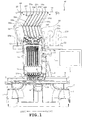
FIG. 1 is a front view of an overall multi-needle sewing machine of one embodiment; -
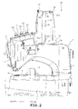
FIG. 2 is a right side view of the multi-needle sewing machine; -
FIG. 3 is a left side view of the multi-needle sewing machine; -
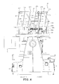
FIG. 4 is a rear view of the multi-needle sewing machine; -
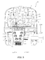
FIG. 5 is a plan view of the multi-needle sewing machine; -
FIG. 6 is a front view of a part of the multi-needle sewing machine from an intermediate thread guide portion moving mechanism to needles; -
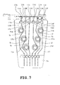
FIG. 7 is a plan view of a thread tension bracket; -
FIGS. 8A and 8B are front views of a needle bar case moving mechanism in two different operating states respectively; -
FIG. 9 is a left side view of the multi-needle sewing machine with a pillar being retracted; -
FIG. 10 is a front view of a thread holding members with the pillar being retracted; -
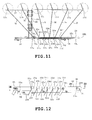
FIG. 11 is a plan view of a part of the multi-needle sewing machine from thread hook members to a machine frame side thread guide member; -
FIG. 12 is a front view of the machine frame side thread guide member; -
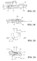
FIG. 13 is a sectional view taken along line XIII-XIII inFIG. 12 ; -
FIG. 14 is a sectional view taken along line XIV-XIV inFIG. 12 ; -
FIG. 15 is a front view of the machine frame side thread guide member; -
FIG. 16 is a sectional view taken along line XVI-XVI inFIG. 15 ; -
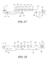
FIG. 17 is a front view of the machine frame side thread guide member with a front side plate member being eliminated; -
FIG. 18 is a view similar toFIG. 17 with an intermediate plate member occupying a different position; -
FIG. 19 is a front view of an intermediate thread guide portion moving mechanism; -
FIG. 20 is a front view of one end of the intermediate thread guide member; -
FIG. 21 is a sectional view taken along line XXI-XXI inFIG. 20 ; -
FIG. 22 is a front view of the intermediate thread guide portion moving mechanism, explaining the operation thereof; -
FIG. 23 is a view similar toFIG. 22 , showing the multi-needle sewing machine of a second embodiment; -
FIG. 24 is a view similar toFIG. 19 , showing the multi-needle sewing machine of a third embodiment; -
FIG. 25 is a view similar toFIG. 24 , showing a different operating state of the intermediate thread guide portion moving mechanism; -
FIG. 26 is a sectional view taken along line XXVI-XXVI inFIG. 24 ; -
FIG. 27 is a sectional view taken along line XXVII-XXVII inFIG. 24 ; -
FIG. 28 is a sectional view taken along line XXVIII-XXVIII inFIG. 24 ; -
FIGS. 29A and 29B are a partial front view and a right side view of the intermediate thread guide portion moving mechanism, showing the multi-needle sewing machine of a fourth embodiment, respectively; -
FIGS. 30A and 30B are similar toFIGS. 29A and 29B , showing the different operating states, respectively; -
FIG. 31 is a sectional view taken along line XXXI-XXXI inFIG. 29A ; -
FIG. 32 is a sectional view taken along line XXXII-XXXII inFIG. 29B ; -
FIG. 33 is a sectional view taken along line XXXIII-XXXIII inFIG. 29A ; -
FIG. 34 is a front view of the intermediate thread guide portion moving mechanism, showing a fifth embodiment; -
FIG. 35 is a view similar toFIG. 34 , showing a different operating state; -
FIG. 36 is a front view of the intermediate thread guide portion moving mechanism, showing a sixth embodiment. - A first embodiment will be described with reference to
FIGS. 1 to 22 . The side of a multi-needle sewing machine M where the user or operator is located is referred to as "front." - Referring to
FIGS. 1 to 5 , the multi-needle sewing machine M includes a pair of right andleft legs 1 supporting the overall sewing machine, apillar 2 standing on rear ends of thelegs 1, anarm 3 extending frontward from an upper part of thepillar 2, acylinder bed 4 extending frontward from a rear end of thepillar 2, and aneedle bar case 5 mounted on a front end of thearm 3. Thelegs 1,pillar 2,arm 3 andcylinder bed 4 are formed integrally with one another into asewing machine body 7. A control device (not shown) controlling the overall multi-needle sewing machine M, anoperation panel 6 and the like are provided at thesewing machine body 7 side. Aneedle plate 4a is mounted on an upper surface of thecylinder bed 4. Theneedle plate 4a is formed with a needle hole (not shown) serving as a needle position forneedles 10a to 10f as will be described later. - A
carriage 8 directed in the right-left direction is disposed above thelegs 1. An X-direction drive mechanism (not shown) is provided inside thecarriage 8 to drive a frame mounting (not shown) in the X direction (the right-left direction). A Y-direction drive mechanism is provided inside thelegs 1 to drive thecarriage 8 in the Y direction (the front-back direction). The frame mounting is located in front of thecarriage 8. A generally rectangular embroidery frame (not shown) holds a workpiece cloth on which embroidery is to be sewn. The embroidery frame is to be mounted on the frame mounting. Thecarriage 8 is driven in the Y direction by the Y-direction drive mechanism, and the frame mounting is driven in the X direction by the X-direction drive mechanism as described above. Accordingly, the embroidery frame is moved in the Y direction in synchronization with thecarriage 8 and in the X direction with the frame mounting, whereby the workpiece cloth is fed. - Six
needle bars 9a to 9f are arranged in the right-left direction so as to extend in the up-down direction in theneedle bar case 5 and supported so as to be movable upward and downward. Sixneedles 10a to 10f are attached to lower ends of the needle bars 9a-9f respectively. Six thread take-uplevers 11 corresponding to therespective needle bars 9a-9f are also provided in theneedle bar case 5 so as to be movable upward and downward. Acover 5a made of a synthetic resin is mounted on a front side of theneedle bar case 5. Athread tension bracket 12 inclined forwardly downward is mounted on the upper surface of theneedle bar case 5 so as to be continuous to the upper end of thecover 5a. Sixcylindrical members 13A to 13F are aligned on a rear end of thethread tension bracket 12 in the right-left direction as shown inFIGS. 6 and7 . Thecylindrical members 13A-13F have hollow interiors serving as thread entrances 13a to 13f respectively. Six auxiliarythread guide portions 14a to 14f are provided on the front sides of the thread entrances 13a-13f respectively. Sixthread tensioners 15a to 15f are mounted on thethread tension bracket 12 to adjust tensions of upper threads supplied to theneedles 10a-10f respectively. - Referring to
FIGS. 8A and 8B , a needle barcase moving mechanism 16 moves theneedle bar case 5 in the right-left direction so that a predetermined one of the sixneedle bars 9a-9f is moved to the needle position that is a sewing position. The needle barcase moving mechanism 16 includes aguide rail 17, sixroller bearings 18, aspiral cam 19, areduction gear assembly 20 and a needle barcase moving motor 21. Theguide rail 17 is mounted on the front end of thearm 3 so as to extend in the right-left direction. The needle-case 5 is supported on theguide rail 17 so as to be slid along theguide rail 17. - The
needle bar case 5 has an upper rear end protruding toward an upper surface of the front end of thearm 3. Theroller bearings 18 are aligned on the upper rear end of theneedle bar case 5 in the right-left direction. Theroller bearings 18 have the same pitch as the needle bars 9a-9f and are pivotally mounted onrespective shafts 18a protruding rearward. Thespiral cam 19 is coupled with ashaft 19a on the upper surface of thearm 3 so as to be rotatable with it. Theshaft 19a is directed in the right-left direction. Rotation of the needle barcase moving motor 21 is transmitted via thereduction gear 20 to theshaft 19a. Thereduction gear 20 is mounted on the upper surface of thearm 3. Thespiral cam 19 is formed with aspiral groove 19b into which eachroller bearing 18 is fittable. Thus, at least one of theroller bearings 18 is fitted in thespiral groove 19b. - The
spiral cam 19 is rotated in a predetermined direction upon rotation of the needle barcase moving motor 21 in a predetermined direction. Theaforesaid roller bearings 18 receive a rightward moving force from thespiral groove 19b such that theneedle bar case 5 is moved rightward. Theneedle bar case 5 is moved leftward when themotor 21 is rotated in the direction opposite the aforesaid predetermined direction. Thus, when theneedle bar case 5 is moved in the right-left direction relative to thesewing machine body 7 by the needle barcase moving mechanism 16, one of six sets of the needle bars 9a-9f and the thread take-uplever 11 is selectively changed to the needle position. The selected one set is moved upward and downward in synchronization with drive of a sewing machine motor (not shown) provided in thepillar 2. Furthermore, one set of the needle bar and the thread take-uplever 11 forms embroidery stitches on the workpiece cloth held on the embroidery frame in cooperation with a rotary hook (not shown) mounted on the front end of thecylinder bed 4. - A
spool holder base 22 is mounted on a fixedframe 3a corresponding to the machine frame mounted on thearm 3 of thesewing machine body 7. Six spool pins 22a stand on thespool holder base 22 so as to be aligned in the right-left direction. Six thread spools 23a to 23f are attached to the spool pins 22a respectively. Athread holding member 24 is provided on a front of the fixedframe 3a and includes asupport holder 25a, asupport 25, a passingmember 26, athread hooking member 27 and a machine frame sidethread guide member 28. Thesupport holder 25a is formed into a generally long cylindrical shape in a planar view and fixed to a front right part of the fixedframe 3a (a part protruding from the arm 3) byscrews 25b so as to stand on the fixedframe 3a. Asupport insertion hole 3b is formed in the front right part of the fixedframe 3a and is slightly larger than a hollow interior of thesupport holder 25a in a planar view as shown inFIG. 10 . - The
support 25 has a lower end that is inserted into thesupport holder 25a and fixed by ascrew 25c. The passingmember 26 is fixed to an upper end of thesupport 25 by ascrew 26a so as to be directed in the front-back direction. Thethread hooking member 27 is fixed to a rear end of the passingmember 26 by ascrew 27g so as to be directed in the right-left direction. Thethread hooking member 27 has six threading holes (seeFIG. 4 ) which are formed therein so as to be located substantially right above therespective spool pins 22a. The machine frame sidethread guide member 28 is fixed to a front end of the passingmember 26 so as to be directed in the right-left direction. - The machine frame side
thread guide member 28 has threeelongate plate members FIGS. 11 to 18 . Theplate members plate members outer plate members spacer 28d (seeFIG. 13 ) and ascrew 28e so that a space allowing movement of theintermediate plate member 28b is defined therebetween. The machine frame sidethread guide member 28 is provided with six machine frame sidethread guide portions 29a to 29f including six outerthread insertion holes 30a to 30f formed in oneouter plate member 28a, six outerthread insertion holes 32a to 32f formed in the otherouter plate member 28c, and six innerthread insertion holes 31a to 31f formed in theintermediate plate member 28b. - The outer
thread insertion holes 30a-30f are formed substantially at regular intervals in theouter plate member 28a. The outerthread insertion holes 32a-32f are also formed substantially at regular intervals in the otherouter plate member 28c so as to correspond to the outerthread insertion holes 30a-30f respectively in a front view. The outer thread insertions holes 30a-30f and 32a-32f have upper portions open at upper ends of theplate members thread insertion holes 31a-31f are formed in theintermediate plate member 28b and have the same intervals as the outerthread insertion holes 30a-30f and 32a-32f. The innerthread insertion holes 31a-31f also have upper portions open at upper ends of theintermediate plate member 28b respectively. - The
intermediate plate member 28b has a left end formed with a guide groove 33 (seeFIG. 17 ) which is directed in the right-left direction and comprises an elongate hole. Theplate member 28b has a right end formed with aguide groove 34 comprising an upwardly directedhole 34a and a horizontally directedelongate hole 34b both of which are continuous to each other. Two guide pins 35 and 36 mounted on theouter plate members guide grooves intermediate plate member 28b is switchable between a use position (a position during sewing) as shown inFIG. 17 and a threading position as shown inFIG. 18 . - When the
intermediate plate member 28b occupies the use position as shown inFIG. 17 , theguide pin 36 is fitted in theupward hole 34a of theguide groove 34 thereby to prevent theintermediate plate member 28b from rightward and leftward movement. In this state, the innerthread insertion holes 31a-31f are shifted in the right direction relative to the outerthread insertion holes 30a-30f and 32a-32f. Furthermore, when theintermediate plate member 28b occupies the threading position as shown inFIG. 18 , the locations of the innerthread insertion holes 31a-31f correspond substantially to the locations of the outerthread insertion holes 30a-30f and 32a-32f respectively. - The outer
thread insertion holes 30a-30f and 32a-32f and the innerthread insertion holes 31a-31f constitute the machine frame side thread guides 29a-39f respectively and further constitute curvingunits 37a-37f respectively. When theintermediate plate member 28b occupies the threading position as shown inFIG. 18 , the thread can be inserted, from above, through the outerthread insertion holes 30a-30f and 32a-32f and the innerthread insertion holes 31a-31f positionally correspond to one another respectively. When theintermediate plate member 28b is moved to the use position as shown inFIG. 17 in this state, the threads are curved by the curvingunits 37a-37f the innerthread insertion holes 31a-31f are shifted in the right direction relative to the outerthread insertion holes 30a-30f and 32a-32f respectively as shown inFIGS. 15 and 16 . Thesupport 25 is movable downward (a retracted position as shown inFIGS. 9 and10 ) in thesupport holder 25a and thesupport insertion hole 3b relative to thesupport holder 25a by loosening thescrew 25c. In this case, an intermediatethread guide member 38 and an intermediate threadguide moving mechanism 39 both of which will be described later are also retracted as well as thesupport 25. - Six intermediate
thread guide portions 38a to 38f are located between the machine frame sidethread guide portions 29a to 29f and the thread entrances 13a-13f respectively as shown inFIGS. 1 and6 . The intermediatethread guide portions 38a-38f are provided on the intermediatethread guide member 38 at the same intervals as the machine frame sidethread guide portions 29a-29f. The intermediatethread guide portions 38a-38f are made by bending metal wire rods generally into a U-shape in a plan view, as shown inFIG. 21 . - The intermediate thread guide
portion moving mechanism 39 moves the intermediatethread guide portions 38a-38f according to movement of theneedle bar case 5 when the thread entrances 13a-13f are moved with the movement of theneedle bar case 5, as shown inFIGS. 1 to 6 and19 . The intermediate thread guideportion moving mechanism 39 includes a pair offirst link members second link members first link members second link members first link member 40 has one (an upper end as viewed inFIGS. 6 and19 ) of two ends that is formed with apivot pin 40a which is mounted on one (a right end as viewed inFIG. 6 ) of two ends of the machine frame sidethread guide member 28 so that thefirst link member 40 is pivotally movable about thepivot pin 40a in a direction of arrow Ra (seeFIG. 19 ). Thefirst link member 40 has the other end that is formed with apivot pin 40b which is mounted on one (a right end as viewed inFIG. 6 ) of two ends of the intermediatethread guide member 38 so that thefirst link member 40 is pivotally movable about thepivot pin 40b in the direction of arrow Ra. - The other
first link member 41 has one (an upper end as viewed inFIGS. 6 and19 ) of two ends that is formed with apivot pin 41a which is mounted on the other end (a left end) of the machine frame sidethread guide member 28 so that thefirst link member 41 is pivotally movable about thepivot pin 41a in the direction f arrow Ra. Thefirst link member 41 has the other end that is formed with apivot pin 41b which is mounted on the other end of the intermediatethread guide member 38 so that thefirst link member 41 is pivotally movable about thepivot pin 41b in the direction of arrow Ra. - A
support piece 44 has asupport shaft 44a, and thesecond link member 42 has one (a lower end as viewed inFIGS. 6 and19 ) of two ends that is mounted on asupport shaft 44a so that thesecond link member 42 is pivotable in the direction of arrow Ra. Thesupport piece 44 is provided near the thread entrance which constitutes one end of the row ofthread entrances 13a-13f of theneedle bar case 5. Furthermore, thesecond link member 42 has the other end (an upper end as viewed inFIGS. 6 and19 ) that is mounted on thepin 40b mounted on the aforesaid one end of the intermediatethread guide member 38 so that thesecond link member 42 is pivotable in the direction of arrow Ra. - A
support piece 45 has asupport shaft 45a, and the othersecond link member 43 has one (a lower end as viewed inFIGS. 6 and19 ) of two ends that is mounted on thesupport shaft 45a so that thesupport piece 45 is pivotable in the direction of arrow Ra. Thesupport piece 45 is provided near the thread entrance which constitutes the other end of the row ofthread entrances 13a-13f of theneedle bar case 5. Furthermore, thesecond link member 43 has the other end that is mounted on thepin 41b mounted on the aforesaid other end of the intermediatethread guide member 38 so that thesecond link member 43 is pivotable in the direction of arrow Ra. - Reference symbols I1, I2 and I3 designate a distance between the
pins pins support shafts first link members second link members first link members second link members thread guide member 38. - Reference symbols C1, C2 and C3 designate a distance between the
pin 41a and the machine frame sidethread guide portion 29a, a distance between thepin 41b and the intermediatethread guide portion 38a and a distance between thesupport shaft 45a and thethread entrance 13a respectively. These distances C1, C2 and C3 are set so as to be equal to one another. Furthermore, reference symbols D1, E1, F1, G1 and H1 designate distances between the machine frame sidethread guide portions 29a-29f respectively. Reference symbols D2, E2, F2, G2 and H2 designate distances between the thread entrances 13a-13f corresponding to the distances D1, E1, F1, G1 and H1, respectively. Reference symbols D3, E3, F3, G3 and H3 designate distances between the thread entrances 13a-13f respectively. These distances D1, E1, F1, G1 and H1, D2, E2, F2, G2 and H2 and D3, E3, F3, G3 and H3 are set so as to be equal to one another, respectively, that is, D1=D2=D3, E1=E2=E3 and so on. - Threads (upper threads) Ia to If of the thread spools 23a-23f are passed through the threading holes 27a-27f, the machine frame side
thread guide portions 29a-29f and the intermediatethread guide portions 38a-38f to be introduced into the thread entrances 13a-13f respectively. The threads having been introduced into the thread entrances 13a-13f are further passed through auxiliarythread guide portions 14a to 14f,thread tensioners 15a to 15f, thread take-uplevers 11 and the like thereafter to be passed through eyes (not shown) of theneedles 10a to 10f, respectively. Accordingly, the intermediatethread guide portions 38a-38f of the intermediatethread guide member 38 guide the intermediate portions of the threads Ia-If between the machine-frame sidethread guide portions 29a-29f serving as a fixed side and the thread entrances 13a-13f serving as a movement side. - The above-described multi-needle sewing machine will work as follows. The
needle bar case 5 is moved by the needle-bar moving mechanism 16 so that one of the needle bars 9a-9f occupies the sewing position P (seeFIG. 6 ). In this case, a leftmost movement position is the position (a position shown by solid line inFIGS. 6 and22 ) where theneedle bar 9f corresponds to the sewing position P. A rightmost movement position is the position (a position shown by two-dot chain line inFIG. 6 ) where theneedle bar 9a corresponds to the sewing position P. The thread entrances 13a-13f are also moved in the right-left direction with the movement of theneedle bar case 5 in the right-left direction.FIG. 22 shows only one thread Ib for the sake of easiness in the explanation of operation of the intermediate thread guideportion moving mechanism 39. However, it is assumed that six threads Ia-If would actually be used. - The lower ends of the
first link members second link members portion moving mechanism 39 are also moved with the movement of theneedle bar case 5. As a result, the first andsecond link members thread guide member 38 is also moved in the right-left direction. In this case, thesecond link members first link members thread guide member 38 is moved in parallel to the rows of the machine frame sidethread guide portions 29a-29f and the thread entrances 13a-13f. As a result, the intermediatethread guide portions 38a-38f are also moved in parallel to one another while being spaced from one another. - The threads Ia-If between the machine frame side
thread guide portions 29a-29f which are at the fixed side and the intermediatethread guide portions 38a-38f of the intermediatethread guide member 38 during the foregoing movement of theneedle bar case 5, respectively. In the embodiment, however, the intermediate portions of the threads Ia-If between the machine frame sidethread guide portions 29a-29f and the thread entrances 13a-13f are guided by the intermediatethread guide portions 38a-38f individually, respectively. Consequently, the threads Ia-If can effectively be prevented from being entangled. In this case, if the intermediatethread guide member 38 should be fixed (immovable) in the same manner as the machine frame sidethread guide portions 29a-29f, it would be difficult to prevent each one of the threads Ia-If between theguide portions 29a-29f and 38a-38f from being entangled with the adjacent threads. In the foregoing embodiment, however, the intermediate thread guideportion moving mechanism 39 moves the intermediatethread guide portions 38a-38f according to the movement of theneedle bar case 5 during the movement of the thread entrances 13a-13f with the movement of theneedle bar case 5 while theguide portions 38a-38f are spaced from one another. Thus, the intermediatethread guide portions 38a-38f are moved between theguide portions 29a-29f and the thread entrances 13a-13f while being spaced from one another. Consequently, the threads Ia-If can be prevented from being entangled with one another, and an occurrence of thread entanglement can reliably be prevented. Moreover, the thread spools 23a-23f are provided on the sewing machine frame (the fixedframe 3a) but not on theneedle bar case 5, which construction differs from the construction of conventional multi-needle sewing machines in which theneedle bar case 5 and the spool holder base to which the thread spools 23a-23f are attached are moved together. Accordingly, the foregoing construction of the embodiment is simplified and rendered more compact as compared with the conventional construction. Additionally, the multi-needle sewing machine M is constructed so that the intermediate portions of the threads Ia-If are guided through the intermediatethread guide portions 38a-38f. This does not necessitate the troublesome work of passing the threads through the elongate tubes respectively, and the threading work can also be simplified. - Furthermore, the intermediate thread guide
portion moving mechanism 39 is constructed into the parallel link mechanism including the pairedfirst link members second link members thread guide portions 38a-38f. Accordingly, the plural intermediatethread guide portions 38a-38f are moved substantially in parallel to the movement direction of the thread entrances 13a-13f. Consequently, an occurrence of thread entanglement can reliably be prevented. Furthermore, when the intermediatethread guide member 38 has been moved by the intermediate thread guideportion moving mechanism 39, the lengths of the threads Ia-If from the machine frame sidethread guide portions 29a-29f to the thread entrances 13a-13f are substantially limited to the length (A+B) of addition of the lengths of the first and second link members 40 (41) and 42 (43). As a result, the threads Ia-If can be prevented from being loosened. - Furthermore, the machine frame side
thread guide portions 29a-29f of the machine frame sidethread guide member 28 includes the curvingunits 37a-37f which curve the threads Ia-If respectively. As a result, a slight passage resistance is applied to each of the threads Ia-If, whereby the behavior of each thread can be rendered more stable. Furthermore, the machine frame sidethread guide member 28 includes threeelongate plate members outer plate members thread insertion holes 30a-30f and 32a-32f whose positions correspond with one another, respectively. Theintermediate plate member 28b is formed with the innerthread insertion holes 31a-31f shifted from the outerthread insertion holes 30a-30f and 32a-32f respectively. Thesethread insertion holes 30a-30f, 31a-31f and 32a-32f constitute the curvingunits 37a-37f respectively. Consequently, the threads Ia-If can be curved easily and reliably. -
FIG. 23 illustrates a second embodiment. Two intermediatethread guide members portion moving mechanism 39 in the second embodiment. The upper intermediatethread guide member 51 is pivotally mounted between the intermediate portions of thefirst link members thread guide member 52 is pivotally mounted between the intermediate portions of thesecond link members thread guide members thread guide portions 51a-51f and 52a-52f guiding the threads Ia-If respectively in the same manner as the intermediatethread guide member 38. Although only one thread Ib is shown inFIG. 23 for the sake of easiness in the explanation of the operation of the intermediate thread guide portion moving mechanism, it is assumed that six threads Ia-If would be provided as shown inFIGS. 1 and6 . - According to the above-described second embodiment, the thread Ia-If can further be prevented from being loosened.
-
FIGS. 24 to 28 illustrate a third embodiment. The third embodiment differs from the first embodiment in the construction of the intermediate thread guideportion moving mechanisms 61a to 61f. The intermediate thread guideportion moving mechanisms 61a to 61f are provided so as to correspond to the intermediatethread guide portions 62a to 62f (shown inFIG. 27 ) respectively. The intermediate thread guideportion moving mechanisms 61a to 61f have respectivefirst arm members 63a to 63f and respectivesecond arm members 64a to 64f.Pins 67a to 67f (seeFIG. 26 ) are mounted on the machine frame side thread guide members so as to be located near themachine frame side 66a to 66f (substantially beneath theguide portions 66a-66f as viewed inFIG. 24 ) respectively. Thefirst arm members 63a-63f have one ends which are pivotally mounted on thepins 67a to 67f respectively.Pins 68a to 68f (shown inFIG. 27 ) are mounted on one ends of thesecond arm members 64a-64f respectively. Thefirst arm members 63a-63f have the other ends which are pivotally mounted on thepins 68a-68f respectively. Thesecond armmembers 64a-64f have the other ends which are pivotally mounted on thecylindrical members 13A to 13F defining the thread entrances 13a-13f so as to be located near the thread entrances, respectively. - The
pins 67a-67f are formed with threadingholes 69a to 69f respectively as shown inFIG. 26 . Thepins 68a-68f serving as pivots for the first andsecond arm members 63a-63f and 64a-64f are formed with the foregoing intermediatethread guide portions 62a to 62f respectively as shown inFIG. 27 . The threads Ia-If passed through machine frame sidethread guide portions 66a-66f are guided through the threading holes 69a-69f, the intermediatethread guide portions 62a-62f and the thread entrances 13a-13f respectively. Although only one thread Ia is shown inFIGS. 24 and25 , it is assumed that six threads Ia-If would be provided. The machine frame sidethread guide member 65 comprises a single plate member in the third embodiment. - According to the third embodiment, the intermediate
thread guide portions 62a-62f are provided on thepins 68a-68f of the intermediate thread guideportion moving mechanisms 61a-61f respectively. Thepins 68a-68f serve as the pivots for the first andsecond arm members 63a-63f and 64a-64f respectively. As the result of the foregoing construction, the intermediatethread guide portions 62a-62f are moved between the machine frameside guide portions 66a-66f and the thread entrances 13a-13f respectively while being spaced from one another. Consequently, the threads can be prevented from being entangled with one another, and an occurrence of thread entanglement can reliably be prevented. Moreover, the multi-needle sewing machine M is simple in construction and compact in size and does not necessitate a complicated work of passing the threads through the respective tubes. - Furthermore, the lengths of the threads Ia-If from the machine frame side
thread guide portions 66a-66f to the thread entrances 13a-13f remain equal to addition (A+B) of the lengths of thefirst arm members 63a-63f and the lengths of thesecond arm members 64a-64f when the intermediatethread guide portions 62a-62f have been moved by the intermediate thread guideportion moving mechanisms 61a-61f, respectively. Consequently, the threads Ia-If can be prevented from being loosened. -
FIGS. 29 to 33 illustrate a fourth embodiment. The fourth embodiment differs from the third embodiment in the following respects. The intermediate thread guideportion moving mechanisms 61a-61f are constructed so as to move the intermediatethread guide portions 62a-62f only in the right-left direction in the third embodiment. In the fourth embodiment, however, the intermediate thread guideportion moving mechanisms 71a to 71f (only two of the six mechanisms are shown) are constructed so as to move the intermediatethread guide portions 72a to 72f (only two of the six guide portions are shown) in the front-back direction as well as in the right-left direction. More specifically, six bidirectional rotation supports 75 are mounted on the machine frame sidethread guide member 65. Thefirst arm members 73a-73f have one ends which are mounted on the bidirectional rotation supports 75 so as to pivot in the directions of arrow Ra and arrows Sa, respectively.Pins 76 are mounted on one end of thesecond arm member 74a-74f respectively. Thefirst arm members 73a-73f have the other ends which are mounted on thepins 76 so as to pivot in the directions of arrows Ra and Sa, respectively. Six bidirectional rotation supports 77 are mounted on thecylindrical members 13A-13F (only two members shown) respectively. Thesecond arm members 74a-74f have the other ends which are mounted on thesupports 77 so as to pivot in the directions of arrows Ra and Sa. - Each
bidirectional rotation support 75 includes apin 75a mounted on the machine frame sidethread guide member 65, asupport body 75b which is mounted on thepin 75a so as to be pivotable in the direction of arrow Ra, as shown inFIG. 31 . The one ends of thefirst arm members bidirectional rotation support 75 so as to be pivotable in the direction of arrow Sa. The intermediatethread guide portions pin 76 as shown inFIG. 32 . - The bidirectional rotation supports 77 include
support bodies 77a which are rotatably mounted around thecylindrical members respective pins 77b mounted thereon. The other ends of thesecond arm members pins 77b so as to be pivotable in the direction of arrow Sa respectively. Consequently, the fourth embodiment can achieve the same effect as the third embodiment. -
FIGS. 34 and35 illustrate a fifth embodiment. The fifth embodiment differs from the first embodiment in the following. The intermediate thread guideportion moving mechanism 81 has a pair ofsupport members thread guide members support member 82 has one end on which apin 82a is mounted. Thepin 82a is mounted on one of two ends of the machine frame sidethread guide member 28 so that the one end of thesupport member 82 is pivotable. Thesupport member 82 has the other end on which apin 82b is mounted. Thepin 82b is mounted on thesupport piece 44 so that thesupport member 82 is pivotable. Thesupport member 82 has anelongate hole 82h in which thepin 82a is fitted so that thesupport member 82 is allowed to be moved upward and downward. - Furthermore, the
other support member 83 has one of two ends on which apin 83a is mounted. The other end of the machine frame sidethread guide member 28 is mounted on thepin 83a so that the one end of thesupport member 83 is pivotable. Apin 83b is mounted on the other end of thesupport member 83. Thepin 83b is further mounted on thesupport piece 45 so that the other end of thesupport member 83 is pivotable. Thesupport member 83 has anelongate hole 83h in which thepin 83a is fitted so that thesupport member 83 is allowed to be moved upward and downward. - The intermediate
thread guide members pins support members thread guide members thread guide portions 38a-38f. - The operating state of the intermediate thread guide
portion moving mechanism 81 as shown inFIG. 34 differs from the operating state thereof as shown inFIG. 35 . The intermediate thread guideportion moving mechanism 81 is operated with movement of theneedle bar case 5. In this case, a leftmost movement position is shown by solid line inFIG. 34 regarding the swinging of thefirst support member 82. A rightmost movement position is shown by a dashed-dotted line Q inFIG. 34 . Six threads Ia-If are assumed to be provided although only two threads Ib and Ic are shown inFIGS. 34 and35 . - According to the fifth embodiment, the intermediate thread guide
portion moving mechanism 81 includes the pairedsupport members thread guide members support members thread guide member 28 and the thread entrances 13a-13f of theneedle bar case 5. The intermediatethread guide members support members -
FIG. 36 illustrates a sixth embodiment. The sixth embodiment differs from the first embodiment in the construction of the intermediate thread guideportion moving mechanism 91. The intermediate thread guideportion moving mechanism 39 is constructed as the link mechanism in the first embodiment and is operated in synchronization with the movement of theneedle bar case 5. On the other hand, the intermediate thread guideportion moving mechanism 91 includes arack 92, apinion 93 and an electric motor (not shown) driving thepinion 93. The intermediatethread guide member 38 including the intermediatethread guide portions 38a-38f is moved in the right-left direction by the motor of themechanism 91. In this case, the motor is driven so that the intermediatethread guide member 38 in the right-left direction in synchronization with the right-left movement of theneedle bar case 5. Consequently, the sixth embodiment can achieve the same effect as the first embodiment. - The foregoing embodiments should not be restrictive and may be modified as follows. The machine frame side thread guide portions may be formed into through holes. The intermediate thread guide portions may be groove-like holes or through holes both formed in plates although the intermediate thread guide portions are made by bending the metal wire rods in the foregoing embodiments. The number of the needle bars may be changed and the number of the intermediate thread guide portions may also be changed according to the number of the needle bars.
Claims (6)
- A multi-needle sewing machine which comprises:a plurality of needle bars (9a-9f) having lower ends to which needles (10a-10f) are attached, respectively;a needle bar case (5) which supports the needles (10a-10f) so that the needles (10a-10f) are movable upward and downward; anda needle bar case moving mechanism (16) which moves the needle bar case (5) so that a predetermined one of the needle bars (9a-9f) is moved to a needle position that is a sewing position, characterized by:a machine frame side thread guide member (28) which is fixed to a machine frame (3a) and has a plurality of machine frame side thread guide portions (29a-29f) which are arranged at predetermined intervals and guide threads (Ia-If) drawn from a plurality of thread spools (23a-23f) provided on the machine frame (3a) respectively;a plurality of thread entrances (13a-13f) which are defined in the needle bar case (5) to introduce the threads (Ia-If) guided by the machine frame side thread guide portions (29a-29f) to the needle sides of the needle bars (9a-9f), respectively;a plurality of intermediate thread guide portions (38a-38f) which are provided between the machine frame side thread guide portions (29a-29f) and the thread entrances (13a-13f) so as to be movable respectively, the intermediate thread guide portions (38a-38f) guiding intermediate portions of the threads (Ia-If) extending from the machine frame side thread guide portions (29a-29f) toward the thread entrances (13a-13f) respectively; andan intermediate thread guide portion moving mechanism (39) which moves the intermediate thread guide portions (38a-38f) according to movement of the needle bar case (5) during movement of the thread entrances (13a-13f) with movement of the needle bar case (5) while the intermediate thread guide portions (38a-38f) are spaced from each other.
- The multi-needle sewing machine according to claim 1, wherein:the intermediate thread guide portions (38a-38f) are provided in the single intermediate thread guide member (38) so as to be aligned;the intermediate thread guide portion moving mechanism (39) includes a pair of first link members (40, 41) and a pair of second link members (42, 43);one (40) of the paired first link members (40, 41) has one of two ends that is pivotally mounted on one of two ends of the machine frame side thread guide member (28) and the other end that is pivotally mounted on one of two ends of the intermediate thread guide member (38);the other first link member (41) has one of two ends that is pivotally mounted on the other end of the machine frame side thread guide member (28) and the other end that is pivotally mounted on the other end of the intermediate thread guide member (38);the thread entrances (13a-13f) are aligned, and one (42) of the paired second link members (42, 43) has one of two ends that is pivotally mounted on a part of the needle bar case (5) near one of two endmost thread entrances and the other end that is pivotally mounted on said one end of the intermediate thread guide member (38);the other (43) of the paired second link members (42,43) has one of two ends that is pivotally mounted on another part of the needle bar case (5) near the other endmost thread entrance and the other end that is pivotally mounted on said the other end of the intermediate thread guide member (38); andthe paired first and second link members (40, 41 and 42, 43) and the intermediate thread guide member (38) constitute a parallel link mechanism.
- The multi-needle sewing machine according to claim 1 or 2, wherein:the plural intermediate thread guide portion moving mechanisms (61a-61f) are provided for the respective intermediate thread guide portions (62a-62f), and the intermediate thread guide portion moving mechanisms (61a-61f) have respective first arm members (63a-63f) and respective second arm members (64a-64f);the first arm members (63a-63f) have one ends that are pivotally mounted near the machine frame side thread guide portions (66a-66f) respectively and the other ends that are pivotally mounted one of two ends of the second arm members (64a-64f), the second arm members (64a-64f) having the other ends that are mounted on parts of the needle bar case (5) near the thread entrances (13a-13f) respectively; andthe intermediate thread guide portions (62a-62f) are provided in pivotally mounted portions (68a-68f) of the first and second arm members (64a-64f) respectively.
- The multi-needle sewing machine according to any one of claims 1-3, wherein:the intermediate thread guide portion moving mechanism (81) includes a pair of support members (82, 83) and a plurality of intermediate thread guide members (84, 85, 86);the thread entrances (13a-13f) are aligned, and one (82) of the paired support members (82, 83) has one of two ends that is pivotally mounted on one of two ends of the machine frame side thread guide member (28) and the other end that is pivotally mounted on a part of the needle bar case (5) near one of two endmost thread entrances (13a-13f);the other support member (83) has one of two ends that is pivotally mounted on the other end of the machine frame side thread guide member (28) and the other end that is pivotally mounted near the other endmost thread entrance;the intermediate thread guide members (84, 85, 86) are pivotally mounted between the support members (82, 83) so as to be parallel with each other; andthe intermediate thread guide portions (84, 85, 86) are provided in the intermediate thread guide members (38a-38f) respectively.
- The multi-needle sewing machine according to any one of claims 1-4, wherein the machine frame side thread guide portions (29a-29f) of the machine frame side thread guide member (28) include curving units (37a-37f) which curve the threads (Ia-If) respectively.
- The multi-needle sewing machine according to claim 5, wherein:the machine frame side thread guide member (28) includes three lengthy plate members (28a, 28b, 28c) stacked one upon another;outer thread insertion holes (30a-30f, 32a-32f) are defined in both outside plate members (28a, 28c) and have locations substantially corresponding to each other, respectively;the intermediate plate member (28b) has an inside thread insertion hole that is defined therein so as to be shifted from the outer thread insertion holes (30a-30f, 32a-32f); andthe outer thread insertion holes (30a-30f, 32a-32f) defined in the respective outer plate members (28a, 28c) and the inside thread insertion hole defined in the intermediate plate member (28b) constitute the respective curving units (37a-37f).
Applications Claiming Priority (1)
| Application Number | Priority Date | Filing Date | Title |
|---|---|---|---|
| JP2009071927A JP4862907B2 (en) | 2009-03-24 | 2009-03-24 | Multi-needle sewing machine |
Publications (1)
| Publication Number | Publication Date |
|---|---|
| EP2233629A2 true EP2233629A2 (en) | 2010-09-29 |
Family
ID=42359548
Family Applications (1)
| Application Number | Title | Priority Date | Filing Date |
|---|---|---|---|
| EP10156094A Withdrawn EP2233629A2 (en) | 2009-03-24 | 2010-03-10 | Multi-needle sewing machine |
Country Status (4)
| Country | Link |
|---|---|
| US (1) | US8651035B2 (en) |
| EP (1) | EP2233629A2 (en) |
| JP (1) | JP4862907B2 (en) |
| CN (1) | CN101845730B (en) |
Cited By (1)
| Publication number | Priority date | Publication date | Assignee | Title |
|---|---|---|---|---|
| WO2017148886A1 (en) * | 2016-03-01 | 2017-09-08 | Pfaff Industriesysteme Und Maschinen Gmbh | Material web fixing device as part of a filter pocket manufacturing system |
Families Citing this family (11)
| Publication number | Priority date | Publication date | Assignee | Title |
|---|---|---|---|---|
| JP4862907B2 (en) | 2009-03-24 | 2012-01-25 | ブラザー工業株式会社 | Multi-needle sewing machine |
| JP2011019700A (en) | 2009-07-15 | 2011-02-03 | Brother Industries Ltd | Spool holder and sewing machine |
| JP2011019699A (en) | 2009-07-15 | 2011-02-03 | Brother Industries Ltd | Spool holder and sewing machine |
| JP2013502974A (en) * | 2009-08-28 | 2013-01-31 | リムサイエンス カンパニー リミテッド | Suture instrument for selecting and supplying sutures |
| JP5532979B2 (en) | 2010-02-01 | 2014-06-25 | ブラザー工業株式会社 | Multi-needle sewing machine |
| RU2530796C1 (en) * | 2013-04-01 | 2014-10-10 | Чээ Сыан Индастриал Ко., Лтд. | Device of replacement of needle bars in sewing machine |
| CN103361899B (en) * | 2013-07-12 | 2014-05-21 | 宁波舒普机电科技有限公司 | Multi-needle bar module for sewing machine |
| US11511452B2 (en) * | 2017-04-25 | 2022-11-29 | Tism Co., Ltd | Punching device |
| US12331443B2 (en) | 2021-08-17 | 2025-06-17 | Inteva Products, Llc | Method and apparatus for auto thread color change |
| US12123119B1 (en) * | 2022-02-08 | 2024-10-22 | John D. Martelli | Independent thread tension apparatus and method |
| CN116536840B (en) * | 2023-05-05 | 2023-11-14 | 广东康特斯织造装备有限公司 | Staggered warp yarn pattern weaving device |
Citations (3)
| Publication number | Priority date | Publication date | Assignee | Title |
|---|---|---|---|---|
| JPH0646676U (en) | 1992-12-07 | 1994-06-28 | 東海工業ミシン株式会社 | Multi-needle embroidery sewing machine |
| JPH0681478U (en) | 1993-05-08 | 1994-11-22 | ハッピー工業株式会社 | Multi-needle embroidery sewing machine |
| JP2006061179A (en) | 2004-08-24 | 2006-03-09 | Barudan Co Ltd | Embroidery sewing machine thread stand |
Family Cites Families (31)
| Publication number | Priority date | Publication date | Assignee | Title |
|---|---|---|---|---|
| US1730431A (en) * | 1924-10-06 | 1929-10-08 | Charles R Keefer | Combined spool holder and tensioner |
| US1690367A (en) * | 1926-09-07 | 1928-11-06 | Frances B Gotchette | Thread rack for sewing machines |
| US2090286A (en) * | 1935-11-05 | 1937-08-17 | Fred D Chura | Spool holder |
| US2940685A (en) * | 1956-01-25 | 1960-06-14 | Glass Willie Fred | Spool and bobbin supporting rack for sewing machines |
| JPS5673765A (en) | 1979-11-15 | 1981-06-18 | Matsushita Electric Works Ltd | Lifting gear for floor underrsection housing box |
| US4351458A (en) * | 1981-02-09 | 1982-09-28 | Wolfe Jack L | Rotary thread spool storage tree |
| JPS5941804Y2 (en) * | 1981-03-23 | 1984-12-04 | 「あ」 「とみ」沢 | Sewing machine thread stand device |
| JPS5898074U (en) | 1981-12-24 | 1983-07-04 | 株式会社ジユ−キ | sewing machine |
| CH659499A5 (en) * | 1983-06-16 | 1987-01-30 | Saurer Ag Adolph | SWITCHABLE BRAKE DEVICE FOR THE THREADS OF AN EMBROIDERY MACHINE. |
| JPS6027877A (en) | 1983-07-25 | 1985-02-12 | Ishida Scales Mfg Co Ltd | Worker identifier |
| JPS6030779A (en) | 1983-07-26 | 1985-02-16 | 日本電子ロツク株式会社 | Padlock |
| CH677509A5 (en) * | 1988-11-30 | 1991-05-31 | Mefina Sa | |
| JPH0544073U (en) | 1991-11-22 | 1993-06-15 | ジユーキ株式会社 | Lock sewing machine thread stand |
| JP2576546Y2 (en) | 1992-10-20 | 1998-07-16 | ブラザー工業株式会社 | Needle thread guide device in multi-needle sewing machine |
| CN1087394A (en) * | 1992-11-17 | 1994-06-01 | 巴利欧马奇克机械股份有限公司 | Multiple-needle sewing machine |
| JPH06312073A (en) | 1993-04-30 | 1994-11-08 | Brother Ind Ltd | Multi-needle embroidery machine thread stand structure |
| JPH0871278A (en) | 1994-09-09 | 1996-03-19 | Janome Sewing Mach Co Ltd | Spool holder device for sewing machine |
| JP3364736B2 (en) * | 1995-09-22 | 2003-01-08 | 東海工業ミシン株式会社 | Sewing machine balance guard |
| CN2303017Y (en) * | 1997-06-25 | 1999-01-06 | 孟安 | Presser feet of sewing machine |
| JP2000008265A (en) | 1998-06-18 | 2000-01-11 | Brother Ind Ltd | Thread entanglement prevention device for multi-needle sewing machine |
| JP3835020B2 (en) | 1998-10-27 | 2006-10-18 | ブラザー工業株式会社 | Spool stand |
| JP3835021B2 (en) | 1998-10-27 | 2006-10-18 | ブラザー工業株式会社 | Spool stand |
| CN2587908Y (en) * | 2002-09-24 | 2003-11-26 | 徐石渊 | Improvement of Transmission Mechanism of Multi-needle Sewing Machine |
| JP3729411B2 (en) | 2003-02-17 | 2005-12-21 | ブラザー工業株式会社 | Sewing machine and thread stand |
| JP3729412B2 (en) | 2003-03-03 | 2005-12-21 | ブラザー工業株式会社 | sewing machine |
| JP2006193240A (en) | 2005-01-11 | 2006-07-27 | Sugiyasu Corp | Table moving device |
| DE502005000661D1 (en) * | 2005-01-12 | 2007-06-14 | Bernina Int Ag | Spool holder for a plurality of upper thread spools |
| JP3138430U (en) | 2007-07-03 | 2008-01-10 | 公臣 藤本 | Telescopic thread stand for large winding sewing thread |
| JP4862907B2 (en) | 2009-03-24 | 2012-01-25 | ブラザー工業株式会社 | Multi-needle sewing machine |
| JP2011019699A (en) | 2009-07-15 | 2011-02-03 | Brother Industries Ltd | Spool holder and sewing machine |
| JP2011019700A (en) | 2009-07-15 | 2011-02-03 | Brother Industries Ltd | Spool holder and sewing machine |
-
2009
- 2009-03-24 JP JP2009071927A patent/JP4862907B2/en active Active
-
2010
- 2010-02-01 US US12/697,856 patent/US8651035B2/en active Active
- 2010-03-10 EP EP10156094A patent/EP2233629A2/en not_active Withdrawn
- 2010-03-24 CN CN2010101428418A patent/CN101845730B/en active Active
Patent Citations (3)
| Publication number | Priority date | Publication date | Assignee | Title |
|---|---|---|---|---|
| JPH0646676U (en) | 1992-12-07 | 1994-06-28 | 東海工業ミシン株式会社 | Multi-needle embroidery sewing machine |
| JPH0681478U (en) | 1993-05-08 | 1994-11-22 | ハッピー工業株式会社 | Multi-needle embroidery sewing machine |
| JP2006061179A (en) | 2004-08-24 | 2006-03-09 | Barudan Co Ltd | Embroidery sewing machine thread stand |
Cited By (2)
| Publication number | Priority date | Publication date | Assignee | Title |
|---|---|---|---|---|
| WO2017148886A1 (en) * | 2016-03-01 | 2017-09-08 | Pfaff Industriesysteme Und Maschinen Gmbh | Material web fixing device as part of a filter pocket manufacturing system |
| US10947653B2 (en) | 2016-03-01 | 2021-03-16 | Pfaff Industriesysteme Und Maschinen Gmbh | Material web fixing device as part of a filter bag manufacturing installation |
Also Published As
| Publication number | Publication date |
|---|---|
| CN101845730A (en) | 2010-09-29 |
| CN101845730B (en) | 2011-08-17 |
| US20100242819A1 (en) | 2010-09-30 |
| US8651035B2 (en) | 2014-02-18 |
| JP4862907B2 (en) | 2012-01-25 |
| JP2010220846A (en) | 2010-10-07 |
Similar Documents
| Publication | Publication Date | Title |
|---|---|---|
| US8651035B2 (en) | Multi-needle sewing machine | |
| US8863677B2 (en) | Multi-needle sewing machine | |
| JP5311986B2 (en) | Multi-needle embroidery sewing machine upper thread feeder | |
| JP2007301299A (en) | Multi-head embroidery machine | |
| JP4857318B2 (en) | Sequin supply device for embroidery machine and embroidery machine | |
| US8893631B2 (en) | Multi-needle sewing machine | |
| EP1806445A1 (en) | Embroidery machine | |
| US8464651B2 (en) | Spool holder and sewing machine provided therewith | |
| KR101032508B1 (en) | Upper thread control device of sewing machine | |
| US8251000B2 (en) | Spool holder and sewing machine provided therewith | |
| KR20140145544A (en) | Embroidering machine | |
| CN101027444A (en) | Multi-needle embroidery machine | |
| CN102051767B (en) | Multihead embroidery machine and tension frame thereof | |
| CN101035943B (en) | Chain-stitch sewing machine | |
| US20110048302A1 (en) | Sewing machine provided with auxiliary table | |
| JP3210727U (en) | sewing machine | |
| JPH0646676U (en) | Multi-needle embroidery sewing machine | |
| JP2009528124A (en) | Upper thread supply device for embroidery machine | |
| EP1847640B1 (en) | Multifunction sewing machine designed to sew fabrics using different layouts and types of stitches | |
| JP3759091B2 (en) | sewing machine | |
| KR200445722Y1 (en) | Cord Yarn Feeder | |
| KR100405180B1 (en) | Embroidery machine | |
| JP3729412B2 (en) | sewing machine | |
| JP2000008265A (en) | Thread entanglement prevention device for multi-needle sewing machine | |
| JPH0636585U (en) | Needle thread guide device for multi-needle sewing machines |
Legal Events
| Date | Code | Title | Description |
|---|---|---|---|
| PUAI | Public reference made under article 153(3) epc to a published international application that has entered the european phase |
Free format text: ORIGINAL CODE: 0009012 |
|
| AK | Designated contracting states |
Kind code of ref document: A2 Designated state(s): AT BE BG CH CY CZ DE DK EE ES FI FR GB GR HR HU IE IS IT LI LT LU LV MC MK MT NL NO PL PT RO SE SI SK SM TR |
|
| AX | Request for extension of the european patent |
Extension state: AL BA ME RS |
|
| STAA | Information on the status of an ep patent application or granted ep patent |
Free format text: STATUS: THE APPLICATION HAS BEEN WITHDRAWN |
|
| 18W | Application withdrawn |
Effective date: 20120503 |