EP2233628A2 - Presser foot for sewing machine - Google Patents
Presser foot for sewing machine Download PDFInfo
- Publication number
- EP2233628A2 EP2233628A2 EP10003092A EP10003092A EP2233628A2 EP 2233628 A2 EP2233628 A2 EP 2233628A2 EP 10003092 A EP10003092 A EP 10003092A EP 10003092 A EP10003092 A EP 10003092A EP 2233628 A2 EP2233628 A2 EP 2233628A2
- Authority
- EP
- European Patent Office
- Prior art keywords
- presser foot
- work material
- main body
- restriction
- restriction member
- Prior art date
- Legal status (The legal status is an assumption and is not a legal conclusion. Google has not performed a legal analysis and makes no representation as to the accuracy of the status listed.)
- Granted
Links
- 238000009958 sewing Methods 0.000 title claims abstract description 52
- 239000000463 material Substances 0.000 claims abstract description 166
- 238000003825 pressing Methods 0.000 claims description 12
- 239000011347 resin Substances 0.000 claims description 5
- 229920005989 resin Polymers 0.000 claims description 5
- 230000006835 compression Effects 0.000 description 11
- 238000007906 compression Methods 0.000 description 11
- 239000004744 fabric Substances 0.000 description 9
- 238000001514 detection method Methods 0.000 description 4
- 238000009957 hemming Methods 0.000 description 4
- 238000004519 manufacturing process Methods 0.000 description 4
- 241000282472 Canis lupus familiaris Species 0.000 description 3
- 230000003247 decreasing effect Effects 0.000 description 3
- 230000015572 biosynthetic process Effects 0.000 description 2
- 230000007547 defect Effects 0.000 description 2
- 230000002452 interceptive effect Effects 0.000 description 2
- 229910001297 Zn alloy Inorganic materials 0.000 description 1
- 238000013459 approach Methods 0.000 description 1
- 230000000694 effects Effects 0.000 description 1
- 238000000034 method Methods 0.000 description 1
Images











Classifications
-
- D—TEXTILES; PAPER
- D05—SEWING; EMBROIDERING; TUFTING
- D05B—SEWING
- D05B29/00—Pressers; Presser feet
- D05B29/06—Presser feet
- D05B29/08—Presser feet comprising relatively-movable parts
Definitions
- This disclosure relates to a presser foot for a sewing machine, which presses a stepped portion of a work material for restricting an unexpected movement of the work material.
- a known presser foot 60 for a sewing machine includes a bottom face 61 having a flat surface, a front presser portion 64, and a rear presser portion 67.
- a needle receiving hole 62 is formed in the center of the bottom face 61.
- the presser foot 60 is configured so that the bottom face 61 surely presses a work material (fabric) to thereby prevent the work material from moving vertically in conjunction with a vertical movement of a sewing needle (such vertical movement of the work material resembles a waving flag and therefore will be referred to as "flagging").
- a work material fabric
- a thickest portion of the stepped portion 10 is fed close to the rotary pin 4 and afterwards passes the rotary pin 4, i.e. the presser foot 60 is moved up on and down from the stepped portion 10.
- the work material may be forcibly moved backward in the opposite direction of a feed direction of the work material because of a presser bar pressure and may not be appropriately fed because of a sudden upward movement of the rotary pin 4.
- a known presser foot disclosed in JP1991-65570U (hereinafter referred to as Reference 1) includes a presser plate rotatably attached to a lower end of a presser holder via a pivot shaft. Recessed portions are formed at lateral sides of a bottom face of the presser plate so as to be positioned approximately directly below the pivot shaft.
- a presser foot for a sewing machine disclosed in JP1996-141251A (hereinafter referred to as Reference 2) includes front and rear presser feet arranged in a feed direction of a work material.
- the front and rear presser feet are rotatably attached to a presser arm.
- a first coil spring is arranged between the front and rear presser feet and a second coil spring is arranged between the rear presser foot and the presser arm.
- the fabric feed control apparatus includes a sensor detecting a stepped portion of a work material (fabric) when a front end or the stepped portion of the work material approaches a contact portion with a presser foot.
- the sensor transmits a detection signal to a CPU.
- the CPU issues a command to reduce a pressure of the presser foot; thereby, a horizontal moving distance of feed dogs is increased.
- the presser foot described in Reference 1 is more easily moved up on and down from a stepped portion of a work material by means of the recessed portions of the bottom face of the presser foot.
- the presser foot is difficultly moved up on a stepped portion of the work material because of a flat portion of the bottom face of the presser foot.
- the presser foot may not prevent a fluttering movement of the work material.
- the presserfoot may not surely press the work material flatly and may not prevent the fluttering movement of the work material while the presser foot is moved up on and down from the stepped portion of the work material.
- the presser foot including the front and rear divided presser feet as described in Reference 2, when the work material is backstitched (reversely fed) in a condition where the front presser foot is moved down from the stepped portion, a rear end of the front presser foot is not moved up on the stepped portion again, therefore causing thread tangling. Further, when the presser foot is attached to the sewing machine, the front presser foot tilts downward, therefore causing a user to have difficulties feeding the work material under the presser foot. Furthermore, the presser foot has a complicated configuration and includes more components, therefore increasing manufacturing costs of the presser foot.
- the sensor detects an inclination of the presser foot and transmits the detection signal to the CPU. Accordingly, the CPU processes the detection signal and outputs the processed detection signal to an actuator controlling the pressure of the presser foot and to an actuator controlling a fabric feed amount. As s result, a feeding condition is adjusted in order to easily feed the stepped portion of the work material.
- the fabric control apparatus includes such sensor and actuators and therefore is applied only to a very expensive sewing machine. Accordingly, the fabric control apparatus may not be applicable to various models of sewing machines.
- a presser foot for a sewing machine comprising a main body capable of being pivotally attached to a presser holder of the sewing machine via a pivot shaft so as to press a work material being sewn by the sewing machine against a work bed of the sewing machine, the main body of the presser foot having:
- the presser foot is formed by two types of components such as the main body (for example, formed by die-cast portion of zinc alloy) and the restriction member including the restriction portion; therefore, materials and a manufacturing process of the presser foot are easily provided.
- the presser foot may be applicable to conventional sewing machines and optionally provided thereto.
- the restriction member and the restriction member are formed with resin so as to form a single-piece member.
- the restriction member is manufactured at low cost and easily attached to the presser foot.
- the restriction portion is an elastic member pressing the work material by means of an elastic force.
- the restriction portion is the elastic member pressing the work material by means of the elastic force and therefore elastically biases the restriction member.
- the restriction member does not need a biasing member (for example, a compression coil spring) for protruding the restriction portion from the bottom face of the main body of the presser foot. As a result, the number of components for the presser foot is minimized.
- At least two or more restriction portions are arranged at the restriction member so that the needle receiving hole is positioned between the restriction portions.
- the movement of the work material around the needle receiving hole is restricted by two imaginary lines defined by the restriction portions (in the case of three or more restriction portions, an imaginary surface defined by the restriction portions); therefore, thread loops are uniformly formed and skipped stitches are inhibited.
- the restriction member includes a supplementary restriction member positioned in the needle receiving hole and holding the work material along a feed direction thereof.
- the bottom face of the main body has inclined portions and a deepest portion between the inclined portions is positioned further rearward than the pivot shaft in the feed direction.
- the inclination of the presser foot when the presser foot is moved up on the stepped portion is decreased, therefore reducing an upward movement of the pivot shaft transmitting a presser bar pressure to the work material.
- the pivot shaft does not necessarily move upward so as to be higher than the thickness of the stepped portion of the work material and the work material is smoothly fed under the presser foot.
- the inclination of the presser foot allows the stepped portion to be pressed along shapes of the inclined portions.
- a rear portion of the bottom face, which is located rearward than the pivot shaft is easily moved up on the stepped portion.
- the upward movement of the pivot shaft gently varies; thereby, the presser foot is easily moved up on and down from the stepped portion.
- the inclined portions are formed so as to extend to the needle receiving hole. Accordingly, in the case of sewing a thin work material, a portion of the thin work material, which is positioned around the needle receiving hole may not be pressed by the main body of the presser foot. However, the main body is combined with the restriction member; thereby the portion of the thin work material around the needle receiving hole is pressed by the restriction member to inhibit skipped stitches accordingly.
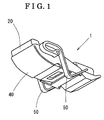
- Fig. 1 is a perspective view of a presser foot for a sewing machine according to a first embodiment disclosed here;
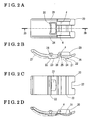
- Fig. 2A is a top view of a main body of the presser foot according to the first embodiment disclosed here;
- Fig. 2B is a lateral view of the main body of the presser foot according to the first embodiment disclosed here;
- Fig. 2C is a bottom view of the main body of the presser foot according to the first embodiment disclosed here;
- Fig. 2D is a cross-sectional view of the main body of the presser foot according to the first embodiment, taken along the line 2D-2D of Fig. 2A ;
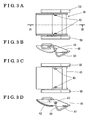
- Fig. 3A is a top view of a restriction member including plate springs according to the first embodiment disclosed here;
- Fig. 3B is a lateral view of the restriction member according to the first embodiment disclosed here;
- Fig. 3C is a bottom view of the restricting member according to the first embodiment disclosed here;
- Fig. 3D is a cross-sectional view of the restriction member according to the first embodiment, taken along the line 3D-3D of Fig. 3A ;
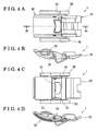
- Fig. 4A is a top view of an assembled condition of the presser foot according to the first embodiment where the restricting member is attached to the main body;
- Fig. 4B is a lateral view of the assembled condition of the presser foot according to the first embodiment
- Fig. Fig. 4C is a bottom view of the presser foot according to the first embodiment
- Fig. 4D is a cross-sectional view showing the assembled condition of the presser foot according to the first embodiment, taken along the line 4D-4D of Fig. 4A ;
- Fig. 5 is an explanation drawing showing a condition before a stepped portion of a work material is moved to a contact position with the presser foot according to the first embodiment
- Fig. 6 is an explanation drawing showing a condition where the presser foot according to the first embodiment starts being moved up on the stepped portion of the work material
- Fig. 7 is an explanation drawing showing a condition where the stepped portion of the work material is moved to a contact position with a front inclined portion of the presser foot according to the first embodiment
- Fig. 8 is an explanation drawing showing a condition where the stepped portion of the work material is further fed close to a rotary pin
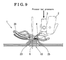
- Fig. 9 is an explanation drawing showing a condition where the stepped portion of the work material is moved directly below the rotary pin
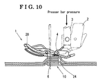
- Fig. 10 is an explanation drawing showing a condition where the stepped portion of the work material passes directly below the rotary pin
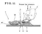
- Fig. 11 is an explanation drawing showing a condition where a terminal portion of the stepped portion of the work material is moved under the rotary pin;
- Fig. 12 is an explanation drawing showing a condition where a rear inclined portion of the main body of the presser foot according to the first embodiment is moved down from the stepped portion of the work material;
- Fig. 13 is an explanation drawing showing a condition where the rear inclined portion of the main body of the presser foot is in contact with the stepped portion of the work material;
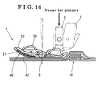
- Fig. 14 is an explanation drawing showing a condition after the presser foot according to the first embodiment is moved down from the stepped portion of the work material;
- Fig. 15 is a perspective view of the presser foot according to a second embodiment disclosed here;
- Fig. 16A is a top view of the main body of the presser foot according to the second embodiment disclosed here;
- Fig. 16B is a lateral view of the main body of the presser foot according to the second embodiment disclosed here;
- Fig. 16C is a bottom view of the main body of the presser foot according to the second embodiment disclosed here;
- Fig. 16D is a cross-sectional view of the main body of the presser foot according to the second embodiment, taken along the line 16D-16D of Fig. 16A ;
- Fig. 17A is a top view of the restriction member according to the second embodiment disclosed here;
- Fig. 17B is a lateral view of the restriction member according to the second embodiment
- Fig. 17C is a bottom view of the restriction member according to the second embodiment.
- Fig. 17D is a cross-sectional view taken of the restriction member according to the second embodiment, taken along the line 17D-17D of Fig. 17A ;
- Fig. 18A is a top view of an assembled condition of the presser foot according to the second embodiment where the restriction member is attached to the main body;
- Fig. 18B is a lateral view of the assembled condition of the presser foot according to the second embodiment
- Fig. Fig. 18C is a bottom view of the assembled condition of the presser foot according to the second embodiment
- Fig. 18D is a cross-sectional view of the presser foot according to the second embodiment, taken along the line 18D-18D of Fig. 18A ;
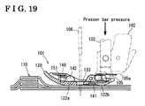
- Fig. 19 is an explanation drawing showing a condition before the stepped portion of the work material is moved to a contact position with the presser foot according to the second embodiment
- Fig. 20 is an explanation drawing showing a condition where the presser foot according to the second embodiment starts being moved up on the stepped portion of the work material;
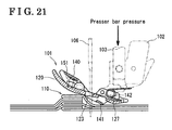
- Fig. 21 is an explanation drawing showing a condition where the stepped portion of the work material is moved to a contact position with the front inclined portion of the presser foot according to the second embodiment
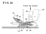
- Fig. 22 is an explanation drawing showing a condition where the stepped portion of the work material is further fed close to the rotary pin;
- Fig. 23 is an explanation drawing showing a condition where the stepped portion of the work material is moved directly below the rotary pin;
- Fig. 24 is an explanation drawing showing a condition where the stepped portion of the work material passes directly below the rotary pin
- Fig. 25 is an explanation drawing showing a condition where the rear inclined portion of the main body of the presser foot according to the second embodiment is moved down from the stepped portion of the work material;
- Fig. 26 is an explanation drawing showing a condition where the rear inclined portion of the main body of the presser foot according to the second embodiment is in contact with the stepped portion of the work material;
- Fig. 27 is an explanation drawing showing a condition after the presser foot according to the second embodiment is moved down from the stepped portion of the work material;
- Fig. 28 is an explanation drawing of a third embodiment that is an modified example of the second embodiment where a supplementary restriction member is attached to the restriction member;
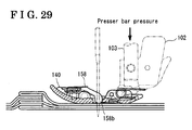
- Fig. 29 is an explanation drawing showing a condition before the stepped portion of the work material is moved to a contact position with the presser foot according to the third embodiment
- Fig. 30 is an explanation drawing illustrating a condition where the stepped portion of the work material is moved to a contact position with the front inclined portion of the presser foot according to the third embodiment
- Fig. 31 is an explanation drawing illustrating a condition where the rear inclined portion of the main body of the presser foot according to the third embodiment is in contact with the stepped portion of the work material;
- Fig. 32 is an perspective view of a known presser foot
- Fig. 33 is an explanation drawing showing a condition while the known presser foot is moved up on the stepped portion of the work material
- Fig. 34 is an explanation drawing showing a condition while the known presser foot is moved up on the stepped portion of the work material.
- Fig. 35 is an explanation drawing showing a condition while the known presser foot is moved down from the stepped portion of the work material.
- an up-and down direction is a vertical direction that coincides with a moving direction of a sewing needle 6.
- a front-and-rear direction corresponds to a feed direction of a work material in the sewing machine.
- Left and right sides in the attached drawings correspond to the front direction and the rear direction, respectively.
- Fig. 1 is a perspective view of the presser foot 1 according to the first embodiment.
- the presser foot 1 includes a main body 20, a restriction member 40 for restricting a vertical movement of the work material, and two plate springs serving as restriction portions (elastic members) 50 attached to the restriction member 40.
- the vertical movement of the work material resembles a waving flag and therefore will be referred to as "flagging" hereinafter.
- the restriction member 40 is to be read as a flagging-preventing member 40.
- Fig. 2A is a top view of the main body 20 of the presser foot 1.
- Fig. 2B is a lateral view of the main body 20.
- Fig. 2C is a bottom view of the main body 20.
- Fig. 2D is a cross-sectional view of the main body 20 taken along the line 2D-2D of Fig. 2A .
- a presser holder 2 transmitting a presser bar pressure of a presser bar spring to the main body 20 is arranged at the main body 2 (see Fig. 5 ).
- the presser holder 2 is fixed to a presser bar 3 that is vertically movable (see Fig. 5 ).
- the main body 20 of the presser foot 1 is movably attached to the presser holder 2 via a pivot pin (pivot shaft) 4.
- a bottom face 21 of the main body 20 of the presser foot 1 includes flat faces 22, a front inclined portion (inclined portion) 23, and a rear inclined portion (inclined portion) 24.
- a deepest portion 25 between the front inclined portion 23 and the rear inclined portion 24 is positioned further rearward than the rotary pin 4.
- a needle receiving hole 33 is formed in the approximately center of the main body 20. The sewing needle 6 penetrates through the needle receiving hole 33.
- a first accommodating portion 27 and a second accommodating portion 28 are arranged in the bottom face 21. The first accommodating portion 27 accommodates a pass over portion 42 (see Fig.
- the bottom face 21 of the main body 20 of the presser foot 1 is flatly connected to either one of the pass over portion 42 and the pressing portion 41.
- first and second recessed potions 31 and 32 are formed in the bottom face 21 for preventing the main body 20 from contacting a contact portion 5 of the presser holder 2.
- Holes 26 are formed in lateral faces of the main body 20. Shafts 43 of the restriction member 40 are inserted into the holes 26 of the main body 20. Furthermore, the rotary pin 4 is attached to the main body 20.
- Fig. 3A is a top view of the restriction member 40 including the plate springs 50.
- Fig. 3B is a lateral view of the restriction member 40.
- Fig. 3C is a bottom view of the restriction member 40.
- Fig. 3D is a cross-sectional view of the restriction member 40 taken along the line 3D-3D of Fig. 3A .
- the restriction member 40 includes the pressing portion 41 and the pass over portion 42.
- the plate springs 50 are attached to lateral faces of the restriction member 40.
- the shafts 43 are arranged at inner portions of the lateral faces of the restriction member 40.
- the restriction member 40 and the plate springs 50 are formed with resin so as to form a single-piece member.
- Fig. 4A is a top view of an assembly condition of the presser foot 1 in which the restriction member 40 is attached to the main body 20.
- Fig. 4B is a lateral view of the assembled condition of the presser foot 1.
- Fig. 4C is a bottom view of the assembled condition of the presser foot 1.
- Fig. 4D is a cross-sectional view of the assembled condition of the presser foot 1 taken along the line 4D-4D of Fig. 4A .
- the shafts 43 are fitted in the holes 26 to thereby movably attach the restriction member 40 to the main body 20.
- Fig. 5 shows a condition before a stepped portion 10 of the work material is fed close to the presser foot 1.
- the presser foot 1 presses (three folds of the stepped portion of) the work material.
- An elastic force of the plate springs 50 of the restriction member 40 is set to be surely smaller than the presser bar pressure. Accordingly, the plate springs 50 are elastically deformed and moved upward as seen in Fig. 5 .
- the pass over portion 42 is accommodated in the accommodating portion 27 of the main body 20 by the presser bar pressure. Furthermore, since the pass over portion 42 is pressed against the work material by the presser bar pressure, a portion of the work material, which is around the needle receiving hole 33, is pressed by the pressing portion 41 via the shafts 43. Such condition is seen similarly in the case of sewing a thin work material, therefore preventing skipped stitches.
- Fig. 6 shows a condition where the presser foot 1 starts being moved up on the stepped portion 10.
- a space 11 having an approximate triangular shape is formed between the presser foot 1 and the work material.
- flagging of the work material is restricted by the elastic force (restoring force) of the plate springs 50 arranged at the restriction member 40 to thereby prevent a non-uniform formation of thread loops. Further, skipped stitches are prevented while the presser foot 1 is moved up on the stepped portion 10.
- Fig. 7 shows a condition where the stepped portion 10 is moved to a contact position with the front inclined portion 23 of the presser foot 1.
- an upper corner of the stepped portion 10 is in contact with the front inclined portion 23 of the main body 20 and the presser bar pressure is not applied to the pass over portion 42 of the restriction member 40.
- the pressing portion 41 is accommodated in the second accommodating portion 28 of the main body 20 by the elastic force (restoring force) of the plate springs 50.
- Fig. 8 shows a condition where the stepped portion 10 of the work material is further fed close to the rotary pin 4.
- the presser bar pressure is stronger than the elastic force of the plate springs 50 and therefore elastically deforms the plate springs 50.
- an inclination ⁇ of the presser foot 1 is reduced by approximately 40 percent as compared with an inclination ⁇ of a known presser foot 60 (see Fig. 34 ).
- a height h1 of the rotary pin 4 from the work material is shorter by approximately 10 percent as compared with a height h2 of the rotary pin 4 of the known presser foot 60 (see Fig. 34 ).
- Fig. 9 shows a condition where the stepped portion 10 of the work material is moved directly below the rotary pin 4.
- the presser bar pressure is applied to a whole area of the front inclined portion 23 of the main body 20 of the presser foot 1. Since the deepest portion 25 that is an inflexion point between the front inclined portion 23 and the rear inclined portion 24 of the main body 20 is located further rearward than the rotary pin 4, the condition shown in Fig. 9 is realized due to the principle of leverage.
- Fig. 10 shows a condition where the stepped portion 10 of the work material passes directly below the rotary pin 4.
- the upper corner of the stepped portion 10 is in contact with the rear inclined portion 24 of the main body 20.
- the height of the rotary pin 4 varies but an amount of the variation is small; therefore, feeding of the work material is not inhibited.
- Fig. 11 shows a terminal portion of the stepped portion 10 of the work material is moved approximately below the rotary pin 4.
- the space 11 having the approximately triangular shape is formed between the stepped portion 10 and the presser foot 1 in the same manner as seen while the presser foot 1 is moved up on the stepped portion 10.
- flagging of the work material is restricted by the plate springs 50 of the restriction member 40; therefore, skipped stitches are inhibited.
- Fig. 12 shows a condition before a rear end inclined portion 29 of the main body 20 of the presser foot 1 is moved down from the stepped portion 10 of the work material.
- the presser foot 1 is moved down from the stepped portion 10 while flagging of the work material in the space 11 formed between the main body 20 and the stepped portion 10 is restricted by the plate springs 50 of the restriction member 40.
- the pressing portion 41 is not in contact with the stepped portion 10 and a load is not applied to the pressing portion 41.
- the pass over portion 42 is accommodated in the first accommodating portion 27 of the main body 20 by the presser bar pressure.
- Fig. 13 shows a condition where the rear end inclined portion 29 of the main body 20 of the presser foot 1 is in contact with the stepped portion 10 of the work material.
- a downwardly inclined angle of the known presser foot 60 is not sufficient for the presser foot 60 to press the work material.
- the stepped portion 10 is moved forcibly or suddenly in the feed direction by a rear end inclined portion 69 of the known presser foot 60 because of the presser bar pressure. Accordingly, a feed amount of the work material is increased. As a result, the sewing needle 6 may be bent by the forcible or sudden movement of the work material.
- a forwardly inclined angle of the main body 20 is increased by the receded portions 31 and 32 preventing the main body 20 from interfering with the contact portion 5 of the presser holder 2 arranged at the main body 20. Further, the work material is held by the presser bar pressure applied to the main body 20, via the pass over portion 42 of the restriction member 40. As a result, the work material is inhibited from being forcibly or suddenly moved in the feed direction.
- Fig. 14 shows a condition after the presser foot 1 is moved down from the stepped portion 10 of the work material.
- the plate springs 50 of the restriction member 40 are elastically deformed and moved upward in the same manner as seen in Fig. 5 .
- the pass over portion 42 is accommodated in the first accommodating portion 27 by the presser bar pressure.
- the restriction member 40 is provided with the plate springs 50 protruding from the bottom face 21 of the main body 20. Accordingly, when the stepped portion 10 is moved to a contact position with a front portion of the presser foot 1, the space 11 having the approximately triangular shape is formed between the stepped portion 10 and the presser foot 1. At this time, the spring plates 50 press the work material to restrict the movement of the work material. Accordingly, thread loops are uniformly formed and skipped stitches are prevented. Such action of the spring plates 50 is effective when the presser foot 1 is moved up on and down from the stepped portion 10.
- the presser foot 1 is formed by two types of components such as the main body 20 and the restriction member 40 including the plate springs 50; therefore, materials and a manufacturing process of the presser foot 1 are easily provided. Furthermore, when the presser foot 1 is applied to the sewing machine, a body of the sewing machine does not require a special configuration. Accordingly, the presser foot 1 may be applicable to conventional sewing machines and optionally provided thereto.
- restriction member 40 and the plate springs 50 are formed with the resin so as to form the single-piece member. Accordingly, the restriction member 40 is manufactured at low cost and easily attached to the presser foot 1.
- the spring member 50 is the elastic member pressing the work material by means of the elastic force and therefore elastically biases the restriction member 40.
- the restriction member 40 does not need a biasing member (for example, a compression coil spring) for protruding the spring plates 50 from the bottom face 21 of the main body 20 of the presser foot 1. As a result, the number of components for the presser foot 1 is minimized.
- the plate springs 50 are arranged at the lateral faces of the restriction member 40 in a condition where the needle receiving hole 33 is positioned between the plate springs 50. Accordingly, the movement of the work material around the needle receiving hole 33 is restricted by two imaginary lines defined by the spring plates 50; therefore, thread loops are uniformly formed.
- the bottom face 21 of the main body 20 of the presser foot 1 is configured so that the deepest portion 25 between the front inclined portion 23 and the rear inclined portion 24 is positioned further rearward than the rotary pin 4. Accordingly, for example, in the case where a stepped portion of a thick work material is sewn (in the case of hemming jeans), the inclination of the presser foot 1 when the presser foot 1 is moved up on the stepped portion is decreased, therefore reducing an upward movement of the rotary pin 4 transmitting the presser bar pressure to the work material.
- the rotary pin 4 does not necessarily move upward due to the position of the deepest portion 25 so as to be higher than the thickness of the stepped portion 10 of the work material; therefore, the work material is smoothly fed under the presser foot 1. Furthermore, after the stepped portion 10 passes the rotary pin 4 in the feed direction, the inclination of the presser foot 1 allows the stepped portion 10 to be pressed along shapes of the front inclined portion 23 and the rear inclined portion 24. Accordingly, a rear portion of the bottom face 21, which is located further rearward than the rotary pin 4 is easily moved up on the stepped portion 10.
- the upward movement of the rotary pin 4 gently varies to thereby allow the presser foot 1 to easily move up on and down from the stepped portion 10.
- the front inclined portion 23 and the rear inclined portion 24 are formed so as to extend to the needle receiving hole 33. Accordingly, when a thin work material is sewn by the sewing machine, a portion of the thin work material, which is around the needle receiving hole 33 may not be pressed by the main body 20 of the presser foot 1. However, the main body 20 is combined with the restriction member 40; thereby the portion of the thin work material around the needle receiving hole 33 is pressed by the restriction member 40. As a result, skipped stitches are inhibited.
- FIG. 15A is a perspective view of the presser foot 101 seen from above.
- Fig. 15B is a perspective view of the presser foot 101 seen from below.
- the presser foot 101 mainly includes a main body 120, a restriction member 140 restricting flagging of a work material, compression coil springs 151 (see Fig. 18 ), and torsion coil springs 152 (see Fig. 18 ).
- Fig. 16A is a top view of the main body 120 of the presser foot 101 according to the second embodiment.
- Fig. 16B is a lateral view of the main body 120.
- Fig. 16C is a bottom view of the main body 120.
- Fig. 16D is a cross-sectional view of the main body 120 taken along the line 16D-16D of Fig. 16A .
- a presser holder 102 transmitting the presser bar pressure of the presser bar spring to the main body 120 is arranged at the main body 120 (see in Fig. 19 ).
- the presser holder 102 is fixed to a presser bar 103 that is vertically movable (see Fig. 19 ).
- the main body 120 is movably attached to the presser holder 102 via a pivot pin (pivot shaft) 104.
- a bottom face 121 of the main body 120 of the presser foot 101 includes a front flat face 122a, a rear flat face 122b, a front inclined portion (inclined portion) 123, and a rear inclined portion (inclined portion) 124.
- a virtual deepest portion 125a between the front inclined portion 123 and the rear inclined portion 124 is positioned further rearward than the rotary pin 104.
- a needle receiving hole 133 is formed in the approximately center of the main body 120.
- a sewing needle 106 (see Fig. 19 ) penetrates through the needle receiving hole 133.
- An accommodating portion 128 is arranged in the bottom face 121. The accommodating portion 128 accommodates a restriction portion 141 (see Fig. 17 ) of the restriction member 140 (see Fig. 17 ).
- the restriction portion 141 is accommodated in the accommodating portion 128 in accordance with a rotation of the restriction member 140 so as to be flatly connected to the bottom face 121 of the main body 120 of the presser foot 101. Further, first and second recessed potions 131 and 132 preventing the main body 120 from contacting a contact portion 105 of the presser holder 102 are formed in the bottom face 121. Holes 126 are formed in lateral faces of the main body 120. Shafts 143 (see Fig. 17 ) of the restriction member 140 are inserted into the holes 126. Furthermore, recessed portions 156 therein retaining the compression coil springs 151 (see Fig. 18 ) and fitting grooves 157 therein retaining the torsion coil springs 152 (see Fig. 18 ) are arranged in the main body 20 of the presser foot 101.
- Fig. 17A is a top view of the restriction member 140 including the restriction portion 141.
- Fig. 17B is a lateral view of the restriction member 140.
- Fig. 17C is a bottom view of the restriction member 140.
- Fig. 17D is a cross-sectional view of the restriction member 140 taken along the line 17D-17D of Fig. Fig. 17 .
- the restriction member 140 includes the restriction portion 141, rotation restriction pins 142, and coil spring retaining portions 150.
- the shafts 143 are arranged at inner portions of lateral faces of the restriction member 140.
- a cross-section of the restriction member 140 is formed so as to conform to shapes of the front inclined portion 123 and the rear inclined portion 124 in a condition where the restriction member 140 is accommodated within the accommodating portion 128 of the main body 120. Under such condition, the virtual deepest portion 125a is set at the restriction member 141.
- Fig. 18A is a top view of an assembly condition of the presser foot 101 in which the restriction member 140 is attached to the main body 120.
- Fig. 18B is a lateral view of the assembled condition of the presser foot 101.
- Fig. 18C is a bottom view of the assembled condition of the presser foot 101.
- Fig. 18D is a cross-sectional view of the assembled condition of the presser foot 101 taken along the line 18D-18D of Fig. 18A .
- the shafts 143 are fitted in the holes 126 to thereby movably attach the restriction member 140 to the main body 120 of the presser foot 101.
- an allowable rotation range of the restriction member 140 is determined by the rotation restriction pins 142 and a restriction surface 127 of the main body 120.
- a load acting in a clockwise direction around the shaft 143 seen in Figs. 18B and 18D is consistently applied to the restriction member 140 by the compression coil springs 151.
- the clockwise direction corresponds to a direction in which the restriction portion 141 of the restriction member 140 protrudes downward from the bottom face 121 of the main body 120 of the presser foot 101.
- flagging of the work material is prevented by the aforementioned action of the compression coil springs 151.
- a load to tilt the whole presser foot 101 rearwardly downward relative to a spring retaining surface 105a (see Fig. 19 ) around the rotary pin 104 is applied to the presser foot 101 by the torsion coil springs 152.
- a feeding failure i.e.
- Fig. 19 shows a condition before the stepped portion 110 of the work material is moved to a contact position with the presser foot 101.
- the presser foot 101 presses (three folds of the stepped portion 110) of the work material.
- An elastic force (restoring force) of the compression coil springs 151 applying the load to the restriction member 140 is set to be surely smaller than the presser bar pressure. Accordingly, the compression coil springs 151 is not resistive to the presser bar pressure to thereby rotate the restriction member 140 around the shafts 143 in a counterclockwise direction and a portion of the work material, which is positioned around the needle receiving hole 133, is pressed by the front flat portion 122a, the rear flat portion 122b, and the restriction portion 141 of the restriction member 140.
- Fig. 20 shows a condition where the presser foot 101 starts being moved up on the stepped portion 110.
- a space 111 having an approximate triangular shape is formed between the presser foot 101 and the work material.
- flagging of the work material is restricted by the restriction portion 141 of the restriction member 140 by the action of the compression coil springs 151. Accordingly, a non-uniform formation of thread loops and an occurrence of skipped stitches are prevented under a condition where the presser foot 101 is moved up on the stepped portion 110.
- Fig. 21 shows a condition where the stepped portion 110 is moved to a contact position with the front inclined portion 123 of the presser foot 101.
- an upper corner of the stepped portion 110 is in contact with the front inclined portion 123 of the main body 120 and the restriction member 140 is further rotated by the action of the compression coil springs 151 to prevent flagging of the work material by the restriction portion 141 accordingly.
- the restriction portion 141 of the restriction member 140 fully protrudes downward from the bottom face 121 of the main body 120 of the presser foot 101.
- the rotation restriction pins 142 are arranged at the restriction member 140.
- the rotation restriction pins 142 adjust the protrusion amount in contact with the restriction surface 127 arranged on the main body 120 of the presser foot 101 in order to prevent the interference between the restriction portion 141 and the sewing needle 106.
- Fig. 22 shows a condition where the stepped portion 110 of the work material is further fed close to the rotary pin 104.
- lower portions 153 of the lateral faces of the restriction member 140 move along the stepped portion 110; thereby the restriction member 140 is rotated around the shafts 143 in the counterclockwise direction and the restriction portion 141 is accommodated in the accommodating portion 128 of the main body 120.
- an inclination ⁇ of the presser foot 101 is reduced by approximately 40 percent as compared with the inclination ⁇ of the known presser foot 60 (see Fig. 34 ).
- a height h1 of the rotary pin 104 from the work material is shorter by approximately 10 percent as compared with the height h2 of the rotary pin 4 of the known presser foot 60. Accordingly, a resistive force (acting in the opposite direction from the feed direction) of the rotary pin 104 relative to the work material, which occurs until the stepped portion 110 is moved directly below the rotary pin 104 is reduced and variations of a load of the presser bar pressure is reduced; thereby, the work material is smoothly fed under the presser foot 101.
- Fig. 23 shows a condition where the stepped portion 110 of the work material is moved directly below the rotary pin 104.
- the presser bar pressure is applied to a whole area of the front inclined portion 123 of the main body 120. Since the virtual deepest portion 125a that is an inflexion point between the front inclined portion 123 and the rear inclined portion 124 of the main body 120 is located further rearward than the rotary pin 104, the condition shown in Fig. 23 is realized due to the principle of leverage.
- Fig. 24 shows a condition where the stepped portion 110 of the work material passes right below the rotary pin 104.
- the upper corner of the stepped portion 110 is in contact with the rear inclined portion 124 of the main body 120.
- the height of the rotary pin 104 varies but an amount of the variation is small; therefore, feeding of the work material is not inhibited.
- Fig. 25 shows a condition where the rear flat portion 122b of the main body 120 is moved down from the stepped portion 110 of the work material.
- the presser foot 101 is moved down from the stepped portion 110 while flagging of the work material in the space 111 having the approximately triangular shape formed between the stepped portion 110 and the main body 120 is restricted by the restriction portion 141 of the restriction member 140. Accordingly, when the work material is backstitched (reversely fed) under such condition shown in Fig. 25 , a rear end portion 155 of the restriction member 140 enables the presser foot 101 to be easily moved up on the stepped portion 110.
- Fig. 26 shows a condition where a rear end inclined portion 129 of the main body 120 of the presser foot 101 is in contact with the stepped portion 110 of the work material.
- the known presser foot 60 illustrated in Fig. 32 does not securely press the work material because the downwardly inclined angle of the known presser foot 60 is not sufficient due to interference between a contact portion 2a of the presser holder 2 and the presser foot 60 as shown in Fig. 35 .
- the feed dogs move lower than the needle plate surface, the stepped portion 10 is suddenly or forcibly moved in the feed direction by the rear end inclined portion 69 of the known presser foot 60 by means of the presser bar pressure; therefore, the feed amount of the work material is increased.
- the sewing needle 6 may be bent by the work material forcibly moved in the feed direction.
- a forwardly inclined angle of the main body 120 is increased by the receded portions 131 and 132 preventing the main body 120 from interfering with the contact portion 105 of the presser holder 102 arranged at the main body 120.
- the work material is held by the presser bar pressure applied to a curved guide portion 154 ( Fig. 16B and Fig. 16D ) of the main body 120. As a result, the work material is inhibited from being forcefully fed in the feed direction.
- Fig. 27 shows a condition after the presser foot 101 is moved down from the stepped portion 110 of the work material.
- the work material is pressed by the restriction member 140 so that the portion of the work material around the needle receiving hole 133 is pressed by the front flat portion 122a, the rear flat portion 122b, and the restriction portion 141.
- Such condition is similarly seen in the case of sewing the thin work material.
- the portion of the thin work material around the needle receiving hole 133 is pressed by the front flat portion 122a, the rear flat portion 122b, and the restriction portion 141 of the restriction member 140, therefore preventing skipped stitches.
- the restriction member 140 is provided with the protruding portion 141 protruding downward from the bottom face 121 of the main body 120. Accordingly, when the stepped portion 110 is moved to a contact position with a front portion of the presser foot 101, the space 111 having the approximately triangular shape is formed between the stepped portion 110 and the presser foot 101. At this time, the restriction portion 141 presses the work material to thereby restrict the movement of the work material. Accordingly, thread loops are uniformly formed and skipped stitches are prevented. Such effect of the restriction portion 141 is seen when the presser foot 101 is moved up on and down from the stepped portion 110.
- the presser foot 101 is formed by four types of components such as the main body 120, the restriction member 140 including the restriction portion 141, the compression coil spring 151, and the torsion coil spring 152 and materials and a manufacturing process of the presser foot 101 are easily provided. Furthermore, when the presser foot 101 is applied to the sewing machine, the body of the sewing machine does not require the special configuration. Accordingly, the presser foot 101 may be applicable to conventional sewing machines and optionally provided thereto.
- restriction member 140 and the restriction portion 141 are integrally molded with resin. Accordingly, the restriction member 140 is easily manufactured at low cost and easily attached to the presser foot 101.
- the bottom face 121 of the main body 120 of the presser foot 101 is configured so that the deepest portion 125a between the front inclined portion 123 and the rear inclined portion 124 is positioned further rearward than the rotary pin 104. Accordingly, for example, in the case where the stepped portion of the thick work material is sewn (in the case of hemming jeans), the inclination of the presser foot 101 when the presser foot 101 is moved up on the stepped portion is decreased, therefore reducing the upward movement of the rotary pin 104 transmitting the presser bar pressure to the work material.
- the rotary pin 104 does not necessarily move upward so as to be higher than the thickness of the stepped portion 110 of the work material and the work material is smoothly fed under the presser foot 101. Furthermore, the inclination of the presser foot 101 allows the stepped portion 110 to be pressed along shapes of the front inclined portion 123 and the rear inclined portion 124. Accordingly, a rear portion of the bottom face 121, which is located further rearward than the rotary pin 104 is easily moved up on the stepped portion 110. The upward movement of the rotary pin 104 gently varies; thereby, the presser foot 101 is easily moved up on and down from the stepped portion 110.
- the front inclined portion 123 and the rear inclined portion 124 are formed so as to extend to the needle receiving hole 133. Accordingly, in the case of sewing the thin work material, the portion of the thin work material around the needle receiving hole 133 may not be pressed by the main body 120 of the presser foot 101. However, the main body 120 is combined with the restriction member 140; thereby the portion of the thin work material around the needle receiving hole 133 is pressed by the restriction member 140 to inhibit skipped stitches accordingly.
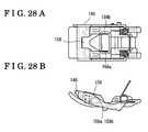
- Fig. 28A and Fig. 28B illustrate a third embodiment that is a modified example of the presser foot 101 according to the second embodiment.
- the presser foot 101 shown in Fig. 28A and Fig. 28B includes the restriction member 140 to which a supplementary restriction member 158 is attached.
- the supplementary restriction member 158 has arm portions 158a and 158b positioned in the needle receiving hole 133 along the feed direction.
- Fig. 28A and Fig. 28B are top and lateral views, respectively, of the presser foot 101 according to the third embodiment.
- Fig. 29 shows a condition where a flat portion of the work material is sewn.
- Fig. 30 shows a condition where the presser foot 101 according to the third embodiment is moved up on the stepped portion 110 of the work material.
- Fig. 31 shows a condition where the presser foot 101 according to the third embodiment is moved down from the stepped portion 110.
- the supplementary restriction member 158 is attached to the restriction member 140 and thereby holds the work material in the needle receiving hole 133 along the feed direction. Accordingly, flagging of the work material is prevented right before the sewing needle 106 moves downward toward and into the needle receiving hole 133. As a result, threat loops are uniformly and effectively formed.
Landscapes
- Engineering & Computer Science (AREA)
- Textile Engineering (AREA)
- Sewing Machines And Sewing (AREA)
Abstract
Description
- This disclosure relates to a presser foot for a sewing machine, which presses a stepped portion of a work material for restricting an unexpected movement of the work material.
- As shown in
Fig. 32 , a knownpresser foot 60 for a sewing machine includes abottom face 61 having a flat surface, afront presser portion 64, and arear presser portion 67. Aneedle receiving hole 62 is formed in the center of thebottom face 61. Thepresser foot 60 is configured so that thebottom face 61 surely presses a work material (fabric) to thereby prevent the work material from moving vertically in conjunction with a vertical movement of a sewing needle (such vertical movement of the work material resembles a waving flag and therefore will be referred to as "flagging"). For example, as shown inFig. 33 , in the case of hemming jeans or sewing belt loops, when astepped portion 10 of the fabric, which includes three, nine, and three folds, is sewn by the sewing machine, thefront presser portion 64 is moved up on thestepped portion 10 via arear end portion 63 of thebottom face 61 serving as a supporting point. Further, since arotary pin 4 is arranged adjacent to therear end portion 63, therotary pin 4 is moved upward simultaneously when thefront presser portion 64 is moved up on thestepped portion 10. - Thus, as illustrated in
Fig. 34 andFig. 35 , a thickest portion of thestepped portion 10 is fed close to therotary pin 4 and afterwards passes therotary pin 4, i.e. thepresser foot 60 is moved up on and down from thestepped portion 10. When the thickest portion of thestepped portion 10 is fed close to therotary pin 4, the work material may be forcibly moved backward in the opposite direction of a feed direction of the work material because of a presser bar pressure and may not be appropriately fed because of a sudden upward movement of therotary pin 4. - Further, as shown in
Fig. 33 , when thefront presser portion 64 is in contact with thestepped portion 10, aspace 68 having an approximately triangular shape is formed by an upper corner of thestepped portion 10, alower end 66 of thestepped portion 10, and therear presser portion 67. Under such condition, the work material in aspace 68 is not surely pressed by thepresser foot 60. Accordingly, when asewing needle 6 penetrates through into the work material, thread loops may not be formed uniformly because the work material is not surely pressed by thepresser foot 60. As a result, sewing defects such as skipped stitches occur. Such sewing defects may occur in a similar way as in the case where thepresser foot 60 is moved down from the stepped portion 10 (seeFig. 35 ). - A known presser foot disclosed in
JP1991-65570U - Further, a presser foot for a sewing machine, disclosed in
JP1996-141251A - Furthermore, a known fabric feed control apparatus for a sewing machine is disclosed in
JP 1993-161771A - The presser foot described in
Reference 1 is more easily moved up on and down from a stepped portion of a work material by means of the recessed portions of the bottom face of the presser foot. However, when the length of the recessed portions is short in a feed direction of a work material, the presser foot is difficultly moved up on a stepped portion of the work material because of a flat portion of the bottom face of the presser foot. When the length of the recessed portion is long in the feed direction, a portion around a needle receiving hole is recessed. Accordingly, the presser foot may not prevent a fluttering movement of the work material. In addition, the presserfoot may not surely press the work material flatly and may not prevent the fluttering movement of the work material while the presser foot is moved up on and down from the stepped portion of the work material. - Moreover, according to the presser foot including the front and rear divided presser feet as described in
Reference 2, when the work material is backstitched (reversely fed) in a condition where the front presser foot is moved down from the stepped portion, a rear end of the front presser foot is not moved up on the stepped portion again, therefore causing thread tangling. Further, when the presser foot is attached to the sewing machine, the front presser foot tilts downward, therefore causing a user to have difficulties feeding the work material under the presser foot. Furthermore, the presser foot has a complicated configuration and includes more components, therefore increasing manufacturing costs of the presser foot. - In addition, according to the fabric feed control apparatus described in
Reference 3, the sensor detects an inclination of the presser foot and transmits the detection signal to the CPU. Accordingly, the CPU processes the detection signal and outputs the processed detection signal to an actuator controlling the pressure of the presser foot and to an actuator controlling a fabric feed amount. As s result, a feeding condition is adjusted in order to easily feed the stepped portion of the work material. The fabric control apparatus includes such sensor and actuators and therefore is applied only to a very expensive sewing machine. Accordingly, the fabric control apparatus may not be applicable to various models of sewing machines. - A need thus exists for an inexpensive presser foot for a sewing machine, which prevents skipped stitches at a stepped portion of a work material, appropriately feeds the work material, and applies to various models of sewing machines.
- According to the invention there is provided a presser foot for a sewing machine according to claim 1 herein. The invention accordingly provides a presser foot for a sewing machine, comprising a main body capable of being pivotally attached to a presser holder of the sewing machine via a pivot shaft so as to press a work material being sewn by the sewing machine against a work bed of the sewing machine, the main body of the presser foot having:
- a needle receiving hole and
- a restriction member or work material control means pivotally attached to the main body and including a portion capable of protruding downwardly from a bottom face of the main body to press against a work material being sewn by the sewing machine even when the presser foot rides up and over a height discontinuity of a stepped portion of the work material being sewn.
- For example, when the stepped portion is moved to a contact position with a front portion of the presser foot, the space having an approximately triangular shape is formed between the stepped portion and the presser foot (in an area where a sewing needle is moved downward). At this time, the restriction portion presses the work material to restrict the movement of the work material. Accordingly, thread loops are uniformly formed and skipped stitches are prevented. Such action of the restriction portion is effective when the presser foot is moved up on and down from the stepped portion. Further, the presser foot is formed by two types of components such as the main body (for example, formed by die-cast portion of zinc alloy) and the restriction member including the restriction portion; therefore, materials and a manufacturing process of the presser foot are easily provided. Furthermore, when the presser foot is applied to the sewing machine, a body of the sewing machine does not require a special configuration. Accordingly, the presser foot may be applicable to conventional sewing machines and optionally provided thereto.
- According to another aspect of the disclosure, the restriction member and the restriction member are formed with resin so as to form a single-piece member.
- Accordingly, the restriction member is manufactured at low cost and easily attached to the presser foot.
- According to further aspect of the disclosure, the restriction portion is an elastic member pressing the work material by means of an elastic force.
- Accordingly, the restriction portion is the elastic member pressing the work material by means of the elastic force and therefore elastically biases the restriction member. Thus, the restriction member does not need a biasing member (for example, a compression coil spring) for protruding the restriction portion from the bottom face of the main body of the presser foot. As a result, the number of components for the presser foot is minimized.
- According to still further aspect of the disclosure, at least two or more restriction portions are arranged at the restriction member so that the needle receiving hole is positioned between the restriction portions.
- Accordingly, the movement of the work material around the needle receiving hole is restricted by two imaginary lines defined by the restriction portions (in the case of three or more restriction portions, an imaginary surface defined by the restriction portions); therefore, thread loops are uniformly formed and skipped stitches are inhibited.
- According to another aspect of the disclosure, the restriction member includes a supplementary restriction member positioned in the needle receiving hole and holding the work material along a feed direction thereof.
- Accordingly, the movement of the work material around the
needle receiving hole 133 is prevented, therefore forming thread loops more effectively. - According to further aspect of the disclosure, wherein the bottom face of the main body has inclined portions and a deepest portion between the inclined portions is positioned further rearward than the pivot shaft in the feed direction.
- Accordingly, for example, in the case where the stepped portion of a thick work material is sewn (in the case of hemming jeans), the inclination of the presser foot when the presser foot is moved up on the stepped portion is decreased, therefore reducing an upward movement of the pivot shaft transmitting a presser bar pressure to the work material. Further, even when the stepped portion is inserted directly under the pivot shaft, the pivot shaft does not necessarily move upward so as to be higher than the thickness of the stepped portion of the work material and the work material is smoothly fed under the presser foot. Furthermore, the inclination of the presser foot allows the stepped portion to be pressed along shapes of the inclined portions. Accordingly, a rear portion of the bottom face, which is located rearward than the pivot shaft is easily moved up on the stepped portion. The upward movement of the pivot shaft gently varies; thereby, the presser foot is easily moved up on and down from the stepped portion. The inclined portions are formed so as to extend to the needle receiving hole. Accordingly, in the case of sewing a thin work material, a portion of the thin work material, which is positioned around the needle receiving hole may not be pressed by the main body of the presser foot. However, the main body is combined with the restriction member; thereby the portion of the thin work material around the needle receiving hole is pressed by the restriction member to inhibit skipped stitches accordingly.
- The foregoing and additional features and characteristics of this disclosure will become more apparent from the following detailed description considered with the reference to the accompanying drawings, wherein:
-
Fig. 1 is a perspective view of a presser foot for a sewing machine according to a first embodiment disclosed here; -
Fig. 2A is a top view of a main body of the presser foot according to the first embodiment disclosed here; -
Fig. 2B is a lateral view of the main body of the presser foot according to the first embodiment disclosed here; -
Fig. 2C is a bottom view of the main body of the presser foot according to the first embodiment disclosed here; -
Fig. 2D is a cross-sectional view of the main body of the presser foot according to the first embodiment, taken along theline 2D-2D ofFig. 2A ; -
Fig. 3A is a top view of a restriction member including plate springs according to the first embodiment disclosed here; -
Fig. 3B is a lateral view of the restriction member according to the first embodiment disclosed here; -
Fig. 3C is a bottom view of the restricting member according to the first embodiment disclosed here; -
Fig. 3D is a cross-sectional view of the restriction member according to the first embodiment, taken along theline 3D-3D ofFig. 3A ; -
Fig. 4A is a top view of an assembled condition of the presser foot according to the first embodiment where the restricting member is attached to the main body; -
Fig. 4B is a lateral view of the assembled condition of the presser foot according to the first embodiment; - Fig.
Fig. 4C is a bottom view of the presser foot according to the first embodiment; -
Fig. 4D is a cross-sectional view showing the assembled condition of the presser foot according to the first embodiment, taken along theline 4D-4D ofFig. 4A ; -
Fig. 5 is an explanation drawing showing a condition before a stepped portion of a work material is moved to a contact position with the presser foot according to the first embodiment; -
Fig. 6 is an explanation drawing showing a condition where the presser foot according to the first embodiment starts being moved up on the stepped portion of the work material; -
Fig. 7 is an explanation drawing showing a condition where the stepped portion of the work material is moved to a contact position with a front inclined portion of the presser foot according to the first embodiment; -
Fig. 8 is an explanation drawing showing a condition where the stepped portion of the work material is further fed close to a rotary pin; -
Fig. 9 is an explanation drawing showing a condition where the stepped portion of the work material is moved directly below the rotary pin; -
Fig. 10 is an explanation drawing showing a condition where the stepped portion of the work material passes directly below the rotary pin; -
Fig. 11 is an explanation drawing showing a condition where a terminal portion of the stepped portion of the work material is moved under the rotary pin; -
Fig. 12 is an explanation drawing showing a condition where a rear inclined portion of the main body of the presser foot according to the first embodiment is moved down from the stepped portion of the work material; -
Fig. 13 is an explanation drawing showing a condition where the rear inclined portion of the main body of the presser foot is in contact with the stepped portion of the work material; -
Fig. 14 is an explanation drawing showing a condition after the presser foot according to the first embodiment is moved down from the stepped portion of the work material; -
Fig. 15 is a perspective view of the presser foot according to a second embodiment disclosed here; -
Fig. 16A is a top view of the main body of the presser foot according to the second embodiment disclosed here; -
Fig. 16B is a lateral view of the main body of the presser foot according to the second embodiment disclosed here; -
Fig. 16C is a bottom view of the main body of the presser foot according to the second embodiment disclosed here; -
Fig. 16D is a cross-sectional view of the main body of the presser foot according to the second embodiment, taken along theline 16D-16D ofFig. 16A ; -
Fig. 17A is a top view of the restriction member according to the second embodiment disclosed here; -
Fig. 17B is a lateral view of the restriction member according to the second embodiment; -
Fig. 17C is a bottom view of the restriction member according to the second embodiment; -
Fig. 17D is a cross-sectional view taken of the restriction member according to the second embodiment, taken along the line 17D-17D ofFig. 17A ; -
Fig. 18A is a top view of an assembled condition of the presser foot according to the second embodiment where the restriction member is attached to the main body; -
Fig. 18B is a lateral view of the assembled condition of the presser foot according to the second embodiment; - Fig.
Fig. 18C is a bottom view of the assembled condition of the presser foot according to the second embodiment; -
Fig. 18D is a cross-sectional view of the presser foot according to the second embodiment, taken along theline 18D-18D ofFig. 18A ; -
Fig. 19 is an explanation drawing showing a condition before the stepped portion of the work material is moved to a contact position with the presser foot according to the second embodiment; -
Fig. 20 is an explanation drawing showing a condition where the presser foot according to the second embodiment starts being moved up on the stepped portion of the work material; -
Fig. 21 is an explanation drawing showing a condition where the stepped portion of the work material is moved to a contact position with the front inclined portion of the presser foot according to the second embodiment; -
Fig. 22 is an explanation drawing showing a condition where the stepped portion of the work material is further fed close to the rotary pin; -
Fig. 23 is an explanation drawing showing a condition where the stepped portion of the work material is moved directly below the rotary pin; -
Fig. 24 is an explanation drawing showing a condition where the stepped portion of the work material passes directly below the rotary pin; -
Fig. 25 is an explanation drawing showing a condition where the rear inclined portion of the main body of the presser foot according to the second embodiment is moved down from the stepped portion of the work material; -
Fig. 26 is an explanation drawing showing a condition where the rear inclined portion of the main body of the presser foot according to the second embodiment is in contact with the stepped portion of the work material; -
Fig. 27 is an explanation drawing showing a condition after the presser foot according to the second embodiment is moved down from the stepped portion of the work material; -
Fig. 28 is an explanation drawing of a third embodiment that is an modified example of the second embodiment where a supplementary restriction member is attached to the restriction member; -
Fig. 29 is an explanation drawing showing a condition before the stepped portion of the work material is moved to a contact position with the presser foot according to the third embodiment; -
Fig. 30 is an explanation drawing illustrating a condition where the stepped portion of the work material is moved to a contact position with the front inclined portion of the presser foot according to the third embodiment; -
Fig. 31 is an explanation drawing illustrating a condition where the rear inclined portion of the main body of the presser foot according to the third embodiment is in contact with the stepped portion of the work material; -
Fig. 32 is an perspective view of a known presser foot; -
Fig. 33 is an explanation drawing showing a condition while the known presser foot is moved up on the stepped portion of the work material; -
Fig. 34 is an explanation drawing showing a condition while the known presser foot is moved up on the stepped portion of the work material; and -
Fig. 35 is an explanation drawing showing a condition while the known presser foot is moved down from the stepped portion of the work material. - A first embodiment of a
presser foot 1 for a sewing machine disclosed here will be explained with reference to the attached drawings. In the following description, an up-and down direction is a vertical direction that coincides with a moving direction of asewing needle 6. A front-and-rear direction corresponds to a feed direction of a work material in the sewing machine. Left and right sides in the attached drawings correspond to the front direction and the rear direction, respectively. -
Fig. 1 is a perspective view of thepresser foot 1 according to the first embodiment. Thepresser foot 1 includes amain body 20, arestriction member 40 for restricting a vertical movement of the work material, and two plate springs serving as restriction portions (elastic members) 50 attached to therestriction member 40. The vertical movement of the work material resembles a waving flag and therefore will be referred to as "flagging" hereinafter. Thus, therestriction member 40 is to be read as a flagging-preventingmember 40. -
Fig. 2A is a top view of themain body 20 of thepresser foot 1.Fig. 2B is a lateral view of themain body 20.Fig. 2C is a bottom view of themain body 20.Fig. 2D is a cross-sectional view of themain body 20 taken along theline 2D-2D ofFig. 2A . Apresser holder 2 transmitting a presser bar pressure of a presser bar spring to themain body 20 is arranged at the main body 2 (seeFig. 5 ). Thepresser holder 2 is fixed to apresser bar 3 that is vertically movable (seeFig. 5 ). Themain body 20 of thepresser foot 1 is movably attached to thepresser holder 2 via a pivot pin (pivot shaft) 4. - As shown in
Figs. 2A to 2D , abottom face 21 of themain body 20 of thepresser foot 1 includes flat faces 22, a front inclined portion (inclined portion) 23, and a rear inclined portion (inclined portion) 24. Adeepest portion 25 between the frontinclined portion 23 and the rearinclined portion 24 is positioned further rearward than therotary pin 4. Aneedle receiving hole 33 is formed in the approximately center of themain body 20. Thesewing needle 6 penetrates through theneedle receiving hole 33. A firstaccommodating portion 27 and a secondaccommodating portion 28 are arranged in thebottom face 21. The firstaccommodating portion 27 accommodates a pass over portion 42 (seeFig. 3 ) of therestriction member 40 in accordance with a rotation of therestriction member 40 while the secondaccommodating portion 28 accommodates a pressing portion 41 (shown inFig. 3 ) pressing the work material around theneedle receiving hole 33, in accordance with the rotation of therestriction member 40. Thus, thebottom face 21 of themain body 20 of thepresser foot 1 is flatly connected to either one of the pass overportion 42 and thepressing portion 41. Further, first and second recessedpotions bottom face 21 for preventing themain body 20 from contacting acontact portion 5 of thepresser holder 2.Holes 26 are formed in lateral faces of themain body 20.Shafts 43 of therestriction member 40 are inserted into theholes 26 of themain body 20. Furthermore, therotary pin 4 is attached to themain body 20. -
Fig. 3A is a top view of therestriction member 40 including the plate springs 50.Fig. 3B is a lateral view of therestriction member 40.Fig. 3C is a bottom view of therestriction member 40.Fig. 3D is a cross-sectional view of therestriction member 40 taken along theline 3D-3D ofFig. 3A . Therestriction member 40 includes thepressing portion 41 and the pass overportion 42. The plate springs 50 are attached to lateral faces of therestriction member 40. Theshafts 43 are arranged at inner portions of the lateral faces of therestriction member 40. Therestriction member 40 and the plate springs 50 are formed with resin so as to form a single-piece member. -
Fig. 4A is a top view of an assembly condition of thepresser foot 1 in which therestriction member 40 is attached to themain body 20.Fig. 4B is a lateral view of the assembled condition of thepresser foot 1.Fig. 4C is a bottom view of the assembled condition of thepresser foot 1.Fig. 4D is a cross-sectional view of the assembled condition of thepresser foot 1 taken along theline 4D-4D ofFig. 4A . Theshafts 43 are fitted in theholes 26 to thereby movably attach therestriction member 40 to themain body 20. - Details of an operation of the
presser foot 1 according to the first embodiment will be described with reference toFigs. 5 to 14 as follows. -
Fig. 5 shows a condition before a steppedportion 10 of the work material is fed close to thepresser foot 1. InFig. 5 , thepresser foot 1 presses (three folds of the stepped portion of) the work material. An elastic force of the plate springs 50 of therestriction member 40 is set to be surely smaller than the presser bar pressure. Accordingly, the plate springs 50 are elastically deformed and moved upward as seen inFig. 5 . Further, the pass overportion 42 is accommodated in theaccommodating portion 27 of themain body 20 by the presser bar pressure. Furthermore, since the pass overportion 42 is pressed against the work material by the presser bar pressure, a portion of the work material, which is around theneedle receiving hole 33, is pressed by thepressing portion 41 via theshafts 43. Such condition is seen similarly in the case of sewing a thin work material, therefore preventing skipped stitches. -
Fig. 6 shows a condition where thepresser foot 1 starts being moved up on the steppedportion 10. Aspace 11 having an approximate triangular shape is formed between thepresser foot 1 and the work material. At this time, flagging of the work material is restricted by the elastic force (restoring force) of the plate springs 50 arranged at therestriction member 40 to thereby prevent a non-uniform formation of thread loops. Further, skipped stitches are prevented while thepresser foot 1 is moved up on the steppedportion 10. -
Fig. 7 shows a condition where the steppedportion 10 is moved to a contact position with the frontinclined portion 23 of thepresser foot 1. In this condition, an upper corner of the steppedportion 10 is in contact with the frontinclined portion 23 of themain body 20 and the presser bar pressure is not applied to the pass overportion 42 of therestriction member 40. Further, thepressing portion 41 is accommodated in the secondaccommodating portion 28 of themain body 20 by the elastic force (restoring force) of the plate springs 50. -
Fig. 8 shows a condition where the steppedportion 10 of the work material is further fed close to therotary pin 4. In this condition, the presser bar pressure is stronger than the elastic force of the plate springs 50 and therefore elastically deforms the plate springs 50. At this time, an inclination α of thepresser foot 1 is reduced by approximately 40 percent as compared with an inclination β of a known presser foot 60 (seeFig. 34 ). Further, a height h1 of therotary pin 4 from the work material is shorter by approximately 10 percent as compared with a height h2 of therotary pin 4 of the known presser foot 60 (seeFig. 34 ). Accordingly, a resistive force (acting in the opposite direction from the feed direction) of therotary pin 4, occurring relative to the work material until the steppedportion 10 is moved directly below therotary pin 4 is reduced and variations of a load of the presser bar pressure is reduced; therefore, the work material is smoothly fed to pass under thepresser foot 1. -
Fig. 9 shows a condition where the steppedportion 10 of the work material is moved directly below therotary pin 4. In this condition, the presser bar pressure is applied to a whole area of the frontinclined portion 23 of themain body 20 of thepresser foot 1. Since thedeepest portion 25 that is an inflexion point between the frontinclined portion 23 and the rearinclined portion 24 of themain body 20 is located further rearward than therotary pin 4, the condition shown inFig. 9 is realized due to the principle of leverage. -
Fig. 10 shows a condition where the steppedportion 10 of the work material passes directly below therotary pin 4. In this condition, the upper corner of the steppedportion 10 is in contact with the rearinclined portion 24 of themain body 20. At this time, the height of therotary pin 4 varies but an amount of the variation is small; therefore, feeding of the work material is not inhibited. -
Fig. 11 shows a terminal portion of the steppedportion 10 of the work material is moved approximately below therotary pin 4. In this condition, thespace 11 having the approximately triangular shape is formed between the steppedportion 10 and thepresser foot 1 in the same manner as seen while thepresser foot 1 is moved up on the steppedportion 10. In addition, flagging of the work material is restricted by the plate springs 50 of therestriction member 40; therefore, skipped stitches are inhibited. -
Fig. 12 shows a condition before a rear end inclinedportion 29 of themain body 20 of thepresser foot 1 is moved down from the steppedportion 10 of the work material. In this condition, thepresser foot 1 is moved down from the steppedportion 10 while flagging of the work material in thespace 11 formed between themain body 20 and the steppedportion 10 is restricted by the plate springs 50 of therestriction member 40. At this time, thepressing portion 41 is not in contact with the steppedportion 10 and a load is not applied to thepressing portion 41. Further, the pass overportion 42 is accommodated in the firstaccommodating portion 27 of themain body 20 by the presser bar pressure. When the work material is backstitched (reversely fed) under the condition shown inFig. 12 , thepresser foot 1 is easily moved up on and down from the steppedportion 10. -
Fig. 13 shows a condition where the rear end inclinedportion 29 of themain body 20 of thepresser foot 1 is in contact with the steppedportion 10 of the work material. As seen inFig. 35 , a downwardly inclined angle of the knownpresser foot 60 is not sufficient for thepresser foot 60 to press the work material. When feed dogs move lower than a needle plate surface, the steppedportion 10 is moved forcibly or suddenly in the feed direction by a rear end inclined portion 69 of the knownpresser foot 60 because of the presser bar pressure. Accordingly, a feed amount of the work material is increased. As a result, thesewing needle 6 may be bent by the forcible or sudden movement of the work material. Meanwhile, according to thepresser foot 1 described in the first embodiment, a forwardly inclined angle of themain body 20 is increased by the recededportions main body 20 from interfering with thecontact portion 5 of thepresser holder 2 arranged at themain body 20. Further, the work material is held by the presser bar pressure applied to themain body 20, via the pass overportion 42 of therestriction member 40. As a result, the work material is inhibited from being forcibly or suddenly moved in the feed direction. -
Fig. 14 shows a condition after thepresser foot 1 is moved down from the steppedportion 10 of the work material. InFig. 14 , the plate springs 50 of therestriction member 40 are elastically deformed and moved upward in the same manner as seen inFig. 5 . In this condition, the pass overportion 42 is accommodated in the firstaccommodating portion 27 by the presser bar pressure. - According to the
press foot 1 of the first embodiment, therestriction member 40 is provided with the plate springs 50 protruding from thebottom face 21 of themain body 20. Accordingly, when the steppedportion 10 is moved to a contact position with a front portion of thepresser foot 1, thespace 11 having the approximately triangular shape is formed between the steppedportion 10 and thepresser foot 1. At this time, thespring plates 50 press the work material to restrict the movement of the work material. Accordingly, thread loops are uniformly formed and skipped stitches are prevented. Such action of thespring plates 50 is effective when thepresser foot 1 is moved up on and down from the steppedportion 10. Further, thepresser foot 1 is formed by two types of components such as themain body 20 and therestriction member 40 including the plate springs 50; therefore, materials and a manufacturing process of thepresser foot 1 are easily provided. Furthermore, when thepresser foot 1 is applied to the sewing machine, a body of the sewing machine does not require a special configuration. Accordingly, thepresser foot 1 may be applicable to conventional sewing machines and optionally provided thereto. - In addition, the
restriction member 40 and the plate springs 50 are formed with the resin so as to form the single-piece member. Accordingly, therestriction member 40 is manufactured at low cost and easily attached to thepresser foot 1. - Moreover, the
spring member 50 is the elastic member pressing the work material by means of the elastic force and therefore elastically biases therestriction member 40. Thus, therestriction member 40 does not need a biasing member (for example, a compression coil spring) for protruding thespring plates 50 from thebottom face 21 of themain body 20 of thepresser foot 1. As a result, the number of components for thepresser foot 1 is minimized. - The plate springs 50 are arranged at the lateral faces of the
restriction member 40 in a condition where theneedle receiving hole 33 is positioned between the plate springs 50. Accordingly, the movement of the work material around theneedle receiving hole 33 is restricted by two imaginary lines defined by thespring plates 50; therefore, thread loops are uniformly formed. - In addition, the
bottom face 21 of themain body 20 of thepresser foot 1 is configured so that thedeepest portion 25 between the frontinclined portion 23 and the rearinclined portion 24 is positioned further rearward than therotary pin 4. Accordingly, for example, in the case where a stepped portion of a thick work material is sewn (in the case of hemming jeans), the inclination of thepresser foot 1 when thepresser foot 1 is moved up on the stepped portion is decreased, therefore reducing an upward movement of therotary pin 4 transmitting the presser bar pressure to the work material. Further, even when the steppedportion 10 is inserted directly under therotary pin 4, therotary pin 4 does not necessarily move upward due to the position of thedeepest portion 25 so as to be higher than the thickness of the steppedportion 10 of the work material; therefore, the work material is smoothly fed under thepresser foot 1. Furthermore, after the steppedportion 10 passes therotary pin 4 in the feed direction, the inclination of thepresser foot 1 allows the steppedportion 10 to be pressed along shapes of the frontinclined portion 23 and the rearinclined portion 24. Accordingly, a rear portion of thebottom face 21, which is located further rearward than therotary pin 4 is easily moved up on the steppedportion 10. The upward movement of therotary pin 4 gently varies to thereby allow thepresser foot 1 to easily move up on and down from the steppedportion 10. In addition, the front inclinedportion 23 and the rearinclined portion 24 are formed so as to extend to theneedle receiving hole 33. Accordingly, when a thin work material is sewn by the sewing machine, a portion of the thin work material, which is around theneedle receiving hole 33 may not be pressed by themain body 20 of thepresser foot 1. However, themain body 20 is combined with therestriction member 40; thereby the portion of the thin work material around theneedle receiving hole 33 is pressed by therestriction member 40. As a result, skipped stitches are inhibited. - A second embodiment of a
presser foot 101 for a sewing machine will be described as follows.Fig. 15A is a perspective view of thepresser foot 101 seen from above.Fig. 15B is a perspective view of thepresser foot 101 seen from below. Thepresser foot 101 mainly includes amain body 120, arestriction member 140 restricting flagging of a work material, compression coil springs 151 (seeFig. 18 ), and torsion coil springs 152 (seeFig. 18 ). -
Fig. 16A is a top view of themain body 120 of thepresser foot 101 according to the second embodiment.Fig. 16B is a lateral view of themain body 120.Fig. 16C is a bottom view of themain body 120.Fig. 16D is a cross-sectional view of themain body 120 taken along theline 16D-16D ofFig. 16A . Apresser holder 102 transmitting the presser bar pressure of the presser bar spring to themain body 120 is arranged at the main body 120 (see inFig. 19 ). Thepresser holder 102 is fixed to apresser bar 103 that is vertically movable (seeFig. 19 ). Themain body 120 is movably attached to thepresser holder 102 via a pivot pin (pivot shaft) 104. - A
bottom face 121 of themain body 120 of thepresser foot 101 includes a frontflat face 122a, a rearflat face 122b, a front inclined portion (inclined portion) 123, and a rear inclined portion (inclined portion) 124. A virtualdeepest portion 125a between the frontinclined portion 123 and the rearinclined portion 124 is positioned further rearward than therotary pin 104. Aneedle receiving hole 133 is formed in the approximately center of themain body 120. A sewing needle 106 (seeFig. 19 ) penetrates through theneedle receiving hole 133. Anaccommodating portion 128 is arranged in thebottom face 121. Theaccommodating portion 128 accommodates a restriction portion 141 (seeFig. 17 ) of the restriction member 140 (seeFig. 17 ). Therestriction portion 141 is accommodated in theaccommodating portion 128 in accordance with a rotation of therestriction member 140 so as to be flatly connected to thebottom face 121 of themain body 120 of thepresser foot 101. Further, first and second recessedpotions main body 120 from contacting acontact portion 105 of thepresser holder 102 are formed in thebottom face 121.Holes 126 are formed in lateral faces of themain body 120. Shafts 143 (seeFig. 17 ) of therestriction member 140 are inserted into theholes 126. Furthermore, recessedportions 156 therein retaining the compression coil springs 151 (seeFig. 18 ) andfitting grooves 157 therein retaining the torsion coil springs 152 (seeFig. 18 ) are arranged in themain body 20 of thepresser foot 101. -
Fig. 17A is a top view of therestriction member 140 including therestriction portion 141.Fig. 17B is a lateral view of therestriction member 140.Fig. 17C is a bottom view of therestriction member 140.Fig. 17D is a cross-sectional view of therestriction member 140 taken along the line 17D-17D of Fig.Fig. 17 . Therestriction member 140 includes therestriction portion 141, rotation restriction pins 142, and coilspring retaining portions 150. Theshafts 143 are arranged at inner portions of lateral faces of therestriction member 140. A cross-section of therestriction member 140 is formed so as to conform to shapes of the frontinclined portion 123 and the rearinclined portion 124 in a condition where therestriction member 140 is accommodated within theaccommodating portion 128 of themain body 120. Under such condition, the virtualdeepest portion 125a is set at therestriction member 141. -
Fig. 18A is a top view of an assembly condition of thepresser foot 101 in which therestriction member 140 is attached to themain body 120.Fig. 18B is a lateral view of the assembled condition of thepresser foot 101.Fig. 18C is a bottom view of the assembled condition of thepresser foot 101.Fig. 18D is a cross-sectional view of the assembled condition of thepresser foot 101 taken along theline 18D-18D ofFig. 18A . Theshafts 143 are fitted in theholes 126 to thereby movably attach therestriction member 140 to themain body 120 of thepresser foot 101. Further, an allowable rotation range of therestriction member 140 is determined by the rotation restriction pins 142 and arestriction surface 127 of themain body 120. Furthermore, a load acting in a clockwise direction around theshaft 143 seen inFigs. 18B and 18D is consistently applied to therestriction member 140 by the compression coil springs 151. The clockwise direction corresponds to a direction in which therestriction portion 141 of therestriction member 140 protrudes downward from thebottom face 121 of themain body 120 of thepresser foot 101. Thus, flagging of the work material is prevented by the aforementioned action of the compression coil springs 151. In addition, a load to tilt thewhole presser foot 101 rearwardly downward relative to aspring retaining surface 105a (seeFig. 19 ) around therotary pin 104 is applied to thepresser foot 101 by the torsion coil springs 152. Thus, a feeding failure (i.e. the work material is not fed appropriately) occurring when thepresser foot 101 is not tilted rearwardly downward, is prevented in the case where thepresser foot 101 is moved up on a steppedportion 110 of the work material. As a result, thepresser foot 101 is easily moved up on the steppedportion 110. - Details of an operation of the
presser foot 101 according to the second embodiment will be described as follows with reference toFigs. 19 to 28 . -
Fig. 19 shows a condition before the steppedportion 110 of the work material is moved to a contact position with thepresser foot 101. InFig. 19 , thepresser foot 101 presses (three folds of the stepped portion 110) of the work material. An elastic force (restoring force) of thecompression coil springs 151 applying the load to therestriction member 140 is set to be surely smaller than the presser bar pressure. Accordingly, the compression coil springs 151 is not resistive to the presser bar pressure to thereby rotate therestriction member 140 around theshafts 143 in a counterclockwise direction and a portion of the work material, which is positioned around theneedle receiving hole 133, is pressed by the frontflat portion 122a, the rearflat portion 122b, and therestriction portion 141 of therestriction member 140. Such condition is seen similarly in the case of sewing a thin work material. Thus, the portion of the thin work material around theneedle receiving hole 133 is pressed by the frontflat portion 122a, the rearflat portion 122b, and therestriction portion 141 of therestriction member 140, therefore preventing skipped stitches. -
Fig. 20 shows a condition where thepresser foot 101 starts being moved up on the steppedportion 110. Aspace 111 having an approximate triangular shape is formed between thepresser foot 101 and the work material. At this time, flagging of the work material is restricted by therestriction portion 141 of therestriction member 140 by the action of the compression coil springs 151. Accordingly, a non-uniform formation of thread loops and an occurrence of skipped stitches are prevented under a condition where thepresser foot 101 is moved up on the steppedportion 110. -
Fig. 21 shows a condition where the steppedportion 110 is moved to a contact position with the frontinclined portion 123 of thepresser foot 101. In this condition, an upper corner of the steppedportion 110 is in contact with the frontinclined portion 123 of themain body 120 and therestriction member 140 is further rotated by the action of thecompression coil springs 151 to prevent flagging of the work material by therestriction portion 141 accordingly. At this time, therestriction portion 141 of therestriction member 140 fully protrudes downward from thebottom face 121 of themain body 120 of thepresser foot 101. When a protrusion amount of therestriction portion 141 is excessively large, therestriction portion 141 may interfere with thesewing needle 106. The rotation restriction pins 142 are arranged at therestriction member 140. The rotation restriction pins 142 adjust the protrusion amount in contact with therestriction surface 127 arranged on themain body 120 of thepresser foot 101 in order to prevent the interference between therestriction portion 141 and thesewing needle 106. -
Fig. 22 shows a condition where the steppedportion 110 of the work material is further fed close to therotary pin 104. In this condition,lower portions 153 of the lateral faces of therestriction member 140 move along the steppedportion 110; thereby therestriction member 140 is rotated around theshafts 143 in the counterclockwise direction and therestriction portion 141 is accommodated in theaccommodating portion 128 of themain body 120. At this time, an inclination α of thepresser foot 101 is reduced by approximately 40 percent as compared with the inclination β of the known presser foot 60 (seeFig. 34 ). Further, a height h1 of therotary pin 104 from the work material is shorter by approximately 10 percent as compared with the height h2 of therotary pin 4 of the knownpresser foot 60. Accordingly, a resistive force (acting in the opposite direction from the feed direction) of therotary pin 104 relative to the work material, which occurs until the steppedportion 110 is moved directly below therotary pin 104 is reduced and variations of a load of the presser bar pressure is reduced; thereby, the work material is smoothly fed under thepresser foot 101. -
Fig. 23 shows a condition where the steppedportion 110 of the work material is moved directly below therotary pin 104. In this condition, the presser bar pressure is applied to a whole area of the frontinclined portion 123 of themain body 120. Since the virtualdeepest portion 125a that is an inflexion point between the frontinclined portion 123 and the rearinclined portion 124 of themain body 120 is located further rearward than therotary pin 104, the condition shown inFig. 23 is realized due to the principle of leverage. -
Fig. 24 shows a condition where the steppedportion 110 of the work material passes right below therotary pin 104. In this condition, the upper corner of the steppedportion 110 is in contact with the rearinclined portion 124 of themain body 120. At this time, the height of therotary pin 104 varies but an amount of the variation is small; therefore, feeding of the work material is not inhibited. -
Fig. 25 shows a condition where the rearflat portion 122b of themain body 120 is moved down from the steppedportion 110 of the work material. Thepresser foot 101 is moved down from the steppedportion 110 while flagging of the work material in thespace 111 having the approximately triangular shape formed between the steppedportion 110 and themain body 120 is restricted by therestriction portion 141 of therestriction member 140. Accordingly, when the work material is backstitched (reversely fed) under such condition shown inFig. 25 , arear end portion 155 of therestriction member 140 enables thepresser foot 101 to be easily moved up on the steppedportion 110. -
Fig. 26 shows a condition where a rear end inclinedportion 129 of themain body 120 of thepresser foot 101 is in contact with the steppedportion 110 of the work material. The knownpresser foot 60 illustrated inFig. 32 does not securely press the work material because the downwardly inclined angle of the knownpresser foot 60 is not sufficient due to interference between a contact portion 2a of thepresser holder 2 and thepresser foot 60 as shown inFig. 35 . For example, when the feed dogs move lower than the needle plate surface, the steppedportion 10 is suddenly or forcibly moved in the feed direction by the rear end inclined portion 69 of the knownpresser foot 60 by means of the presser bar pressure; therefore, the feed amount of the work material is increased. As a result, thesewing needle 6 may be bent by the work material forcibly moved in the feed direction.
Meanwhile, according to thepresser foot 101 described in the second embodiment, a forwardly inclined angle of themain body 120 is increased by the recededportions main body 120 from interfering with thecontact portion 105 of thepresser holder 102 arranged at themain body 120. Further, the work material is held by the presser bar pressure applied to a curved guide portion 154 (Fig. 16B and Fig. 16D ) of themain body 120. As a result, the work material is inhibited from being forcefully fed in the feed direction. -
Fig. 27 shows a condition after thepresser foot 101 is moved down from the steppedportion 110 of the work material. In this condition, the work material is pressed by therestriction member 140 so that the portion of the work material around theneedle receiving hole 133 is pressed by the frontflat portion 122a, the rearflat portion 122b, and therestriction portion 141. Such condition is similarly seen in the case of sewing the thin work material. Thus, the portion of the thin work material around theneedle receiving hole 133 is pressed by the frontflat portion 122a, the rearflat portion 122b, and therestriction portion 141 of therestriction member 140, therefore preventing skipped stitches. - According to the
press foot 101 of the second embodiment, therestriction member 140 is provided with the protrudingportion 141 protruding downward from thebottom face 121 of themain body 120. Accordingly, when the steppedportion 110 is moved to a contact position with a front portion of thepresser foot 101, thespace 111 having the approximately triangular shape is formed between the steppedportion 110 and thepresser foot 101. At this time, therestriction portion 141 presses the work material to thereby restrict the movement of the work material. Accordingly, thread loops are uniformly formed and skipped stitches are prevented. Such effect of therestriction portion 141 is seen when thepresser foot 101 is moved up on and down from the steppedportion 110. Further, thepresser foot 101 is formed by four types of components such as themain body 120, therestriction member 140 including therestriction portion 141, thecompression coil spring 151, and thetorsion coil spring 152 and materials and a manufacturing process of thepresser foot 101 are easily provided. Furthermore, when thepresser foot 101 is applied to the sewing machine, the body of the sewing machine does not require the special configuration. Accordingly, thepresser foot 101 may be applicable to conventional sewing machines and optionally provided thereto. - In addition, the
restriction member 140 and therestriction portion 141 are integrally molded with resin. Accordingly, therestriction member 140 is easily manufactured at low cost and easily attached to thepresser foot 101. - Moreover, the
bottom face 121 of themain body 120 of thepresser foot 101 is configured so that thedeepest portion 125a between the frontinclined portion 123 and the rearinclined portion 124 is positioned further rearward than therotary pin 104. Accordingly, for example, in the case where the stepped portion of the thick work material is sewn (in the case of hemming jeans), the inclination of thepresser foot 101 when thepresser foot 101 is moved up on the stepped portion is decreased, therefore reducing the upward movement of therotary pin 104 transmitting the presser bar pressure to the work material. Further, even when the steppedportion 110 is inserted directly under therotary pin 104, therotary pin 104 does not necessarily move upward so as to be higher than the thickness of the steppedportion 110 of the work material and the work material is smoothly fed under thepresser foot 101. Furthermore, the inclination of thepresser foot 101 allows the steppedportion 110 to be pressed along shapes of the frontinclined portion 123 and the rearinclined portion 124. Accordingly, a rear portion of thebottom face 121, which is located further rearward than therotary pin 104 is easily moved up on the steppedportion 110. The upward movement of therotary pin 104 gently varies; thereby, thepresser foot 101 is easily moved up on and down from the steppedportion 110. The frontinclined portion 123 and the rearinclined portion 124 are formed so as to extend to theneedle receiving hole 133. Accordingly, in the case of sewing the thin work material, the portion of the thin work material around theneedle receiving hole 133 may not be pressed by themain body 120 of thepresser foot 101. However, themain body 120 is combined with therestriction member 140; thereby the portion of the thin work material around theneedle receiving hole 133 is pressed by therestriction member 140 to inhibit skipped stitches accordingly. -
Fig. 28A and Fig. 28B illustrate a third embodiment that is a modified example of thepresser foot 101 according to the second embodiment. Thepresser foot 101 shown inFig. 28A and Fig. 28B includes therestriction member 140 to which asupplementary restriction member 158 is attached. Thesupplementary restriction member 158 hasarm portions needle receiving hole 133 along the feed direction.Fig. 28A and Fig. 28B are top and lateral views, respectively, of thepresser foot 101 according to the third embodiment.
Fig. 29 shows a condition where a flat portion of the work material is sewn.Fig. 30 shows a condition where thepresser foot 101 according to the third embodiment is moved up on the steppedportion 110 of the work material.Fig. 31 shows a condition where thepresser foot 101 according to the third embodiment is moved down from the steppedportion 110. - The
supplementary restriction member 158 is attached to therestriction member 140 and thereby holds the work material in theneedle receiving hole 133 along the feed direction. Accordingly, flagging of the work material is prevented right before thesewing needle 106 moves downward toward and into theneedle receiving hole 133. As a result, threat loops are uniformly and effectively formed. - The principles, preferred embodiment and mode of operation of the present invention have been described in the foregoing specification. However, the invention which is intended to be protected is not to be construed as limited to the particular embodiments disclosed. Further, the embodiments described herein are to be regarded as illustrative rather than restrictive. Variations and changes may be made by others, and equivalents employed, without departing from the spirit of the present invention. Accordingly, it is expressly intended that all such variations, changes and equivalents which fall within the spirit and scope of the present invention as defined in the claims, be embraced thereby.
Claims (6)
- A presser foot (1) for a sewing machine, comprising:a main body (20,120) rotatably attached to a presser holder (2,102) via a pivot shaft (4,104) and having a needle receiving hole (33,133); and
a restriction member (40,140) rotatably attached to the main body (20,120),
wherein the restriction member (40,140) includes a restriction portion (50,141), which protrudes downwardly from a bottom face (21,121) of the main body (20,120) to press a work material to thereby restrict a movement of the work material when a stepped portion (10) of the work material is in contact with the presser foot (1). - The presser foot (1) according to Claim 1, wherein the restriction member (40) and the restriction portion (50) are formed in one-piece resin member.
- The presser foot (1) according to Claim 1 or 2, wherein the restriction portion (50) comprises an elastic member for elastically pressing against the work material.
- The presser foot (1) according to any one of Claims 1 to 3, wherein the restriction portion (50) comprises a plurality of restriction portions (50) which are arranged at the restriction member (40) such that the needle receiving hole (33) is positioned between the restriction portions (50).
- The presser foot (110) according to any one of Claims 1 to 4, wherein the restriction member (140) includes a supplementary restriction member (158) positioned in the needle receiving hole (133) and holding the work material along a feed direction thereof.
- The presser foot (1, 110) according to any one of Claims 1 to 5, wherein the bottom face (21, 121) of the main body (20, 120) has inclined portions (23; 24, 123; 124) and a deepest portion (25, 125a) between the inclined portions (23; 24, 123; 124) is positioned further rearward than the pivot shaft (4, 104) in the feed direction.
Applications Claiming Priority (2)
| Application Number | Priority Date | Filing Date | Title |
|---|---|---|---|
| JP2009079928 | 2009-03-27 | ||
| JP2010055693A JP5963388B2 (en) | 2009-03-27 | 2010-03-12 | Sewing presser foot |
Publications (3)
| Publication Number | Publication Date |
|---|---|
| EP2233628A2 true EP2233628A2 (en) | 2010-09-29 |
| EP2233628A3 EP2233628A3 (en) | 2011-10-05 |
| EP2233628B1 EP2233628B1 (en) | 2013-04-24 |
Family
ID=42342550
Family Applications (1)
| Application Number | Title | Priority Date | Filing Date |
|---|---|---|---|
| EP20100003092 Not-in-force EP2233628B1 (en) | 2009-03-27 | 2010-03-24 | Presser foot for sewing machine |
Country Status (3)
| Country | Link |
|---|---|
| EP (1) | EP2233628B1 (en) |
| JP (1) | JP5963388B2 (en) |
| CN (1) | CN101845717B (en) |
Cited By (2)
| Publication number | Priority date | Publication date | Assignee | Title |
|---|---|---|---|---|
| ITVR20110110A1 (en) * | 2011-05-20 | 2012-11-21 | Vi Be Mac Spa | PREMISTOFFA DEVICE AND SEWING MACHINE INCLUDING THIS DEVICE |
| EP2770099A1 (en) * | 2013-02-22 | 2014-08-27 | Aisin Seiki Kabushiki Kaisha | Embroidery presser of sewing machine |
Families Citing this family (1)
| Publication number | Priority date | Publication date | Assignee | Title |
|---|---|---|---|---|
| CN106192230A (en) * | 2016-08-31 | 2016-12-07 | 江苏红豆实业股份有限公司 | A kind of sewing-machine foot preventing color fourth bar from sliding |
Citations (3)
| Publication number | Priority date | Publication date | Assignee | Title |
|---|---|---|---|---|
| JPH05161771A (en) | 1991-12-18 | 1993-06-29 | Juki Corp | Fabric conveyance control device for sewing machine |
| JPH08141251A (en) | 1994-11-18 | 1996-06-04 | Brother Ind Ltd | Cloth foot for step sewing |
| JP3065570U (en) | 1999-07-08 | 2000-02-02 | 祐文 伊藤 | calendar- |
Family Cites Families (11)
| Publication number | Priority date | Publication date | Assignee | Title |
|---|---|---|---|---|
| US1501901A (en) * | 1922-05-26 | 1924-07-22 | Singer Mfg Co | Presser foot for sewing machines |
| US2147128A (en) * | 1937-04-27 | 1939-02-14 | Singer Mfg Co | Presser-foot for sewing machines |
| US2481175A (en) * | 1944-02-28 | 1949-09-06 | Willcox & Gibbs Sewing Machine | Presser foot |
| US2478073A (en) * | 1947-04-29 | 1949-08-02 | Antonelli Bruno | Adjustable work gauging and guiding presser foot |
| US3334605A (en) * | 1966-11-07 | 1967-08-08 | Ronald J Boser | Adjustable pressure foot construction for sewing machines |
| JPS5153816Y2 (en) * | 1971-02-25 | 1976-12-22 | ||
| DE2210996B2 (en) * | 1972-03-08 | 1974-05-16 | Dorina Naehmaschinen Gmbh, 7500 Karlsruhe | Presser foot for sewing machines |
| JPS5934460Y2 (en) * | 1981-02-09 | 1984-09-25 | 晃信精密機械株式会社 | Presser foot for sewing machine |
| DE3603506C1 (en) * | 1986-02-05 | 1987-07-30 | Union Special Gmbh | Presser foot device |
| US6523791B2 (en) * | 2000-06-01 | 2003-02-25 | Panduit Corp. | Cable duct coupler |
| US6634308B1 (en) * | 2002-05-03 | 2003-10-21 | Alan Roy Martin | Presser foot for high seam stitching |
-
2010
- 2010-03-12 JP JP2010055693A patent/JP5963388B2/en not_active Expired - Fee Related
- 2010-03-24 EP EP20100003092 patent/EP2233628B1/en not_active Not-in-force
- 2010-03-26 CN CN 201010141514 patent/CN101845717B/en not_active Expired - Fee Related
Patent Citations (3)
| Publication number | Priority date | Publication date | Assignee | Title |
|---|---|---|---|---|
| JPH05161771A (en) | 1991-12-18 | 1993-06-29 | Juki Corp | Fabric conveyance control device for sewing machine |
| JPH08141251A (en) | 1994-11-18 | 1996-06-04 | Brother Ind Ltd | Cloth foot for step sewing |
| JP3065570U (en) | 1999-07-08 | 2000-02-02 | 祐文 伊藤 | calendar- |
Cited By (5)
| Publication number | Priority date | Publication date | Assignee | Title |
|---|---|---|---|---|
| ITVR20110110A1 (en) * | 2011-05-20 | 2012-11-21 | Vi Be Mac Spa | PREMISTOFFA DEVICE AND SEWING MACHINE INCLUDING THIS DEVICE |
| EP2535449A1 (en) | 2011-05-20 | 2012-12-19 | VI.BE.MAC. S.p.A. | Presser device and sewing machine comprising said device |
| RU2540394C2 (en) * | 2011-05-20 | 2015-02-10 | ВИ.БЕ.МАК. С.п.А. | Clamping device and sewing machine comprising clamping device |
| TWI503461B (en) * | 2011-05-20 | 2015-10-11 | Vi Be Mac Spa | A presser foot device and a sewing machine comprising the device |
| EP2770099A1 (en) * | 2013-02-22 | 2014-08-27 | Aisin Seiki Kabushiki Kaisha | Embroidery presser of sewing machine |
Also Published As
| Publication number | Publication date |
|---|---|
| JP5963388B2 (en) | 2016-08-03 |
| CN101845717B (en) | 2013-07-10 |
| JP2010246897A (en) | 2010-11-04 |
| EP2233628B1 (en) | 2013-04-24 |
| EP2233628A3 (en) | 2011-10-05 |
| CN101845717A (en) | 2010-09-29 |
Similar Documents
| Publication | Publication Date | Title |
|---|---|---|
| EP2233628B1 (en) | Presser foot for sewing machine | |
| US7867034B1 (en) | Card connector | |
| EP2517594B1 (en) | Slider for slide fastener | |
| EP2028042B1 (en) | Vehicle seat | |
| RU2540394C2 (en) | Clamping device and sewing machine comprising clamping device | |
| CN101824710B (en) | Sewing machine cloth return guide device | |
| US11225178B2 (en) | Slim headrest device | |
| US8770507B2 (en) | Self-locking belt retractor | |
| US20090056607A1 (en) | Cloth pressing device of sewing machine | |
| US5690040A (en) | Presser foot device for feeding elastic member | |
| CN222100315U (en) | Sewing machine presser foot and sewing machine with same | |
| US20220314853A1 (en) | Backboard assembly for vehicular rear seat | |
| CN105401345A (en) | Sewing machine presser foot | |
| JP6090345B2 (en) | Sewing presser foot | |
| JP2016137027A (en) | Presser adjustment mechanism of sewing machine | |
| US20230416960A1 (en) | Sewing machine provided with adjusting mechanism adjusting pressing force applied to workpiece | |
| JP2024004096A (en) | Presser foot device and sewing machine | |
| JP4420050B2 (en) | Sewing machine presser and sewing machine | |
| JP7031475B2 (en) | Presser device | |
| JP2550836Y2 (en) | Sewing machine presser foot device | |
| KR200315322Y1 (en) | Sewing foot for sewing machine | |
| JPH05153Y2 (en) | ||
| JP3427925B2 (en) | connector | |
| JP2016037282A (en) | Seat belt assist device and vehicle seat | |
| JP2556833Y2 (en) | Velvet sewing presser for needle feed sewing machine |
Legal Events
| Date | Code | Title | Description |
|---|---|---|---|
| PUAI | Public reference made under article 153(3) epc to a published international application that has entered the european phase |
Free format text: ORIGINAL CODE: 0009012 |
|
| AK | Designated contracting states |
Kind code of ref document: A2 Designated state(s): AT BE BG CH CY CZ DE DK EE ES FI FR GB GR HR HU IE IS IT LI LT LU LV MC MK MT NL NO PL PT RO SE SI SK SM TR |
|
| AX | Request for extension of the european patent |
Extension state: AL BA ME RS |
|
| PUAL | Search report despatched |
Free format text: ORIGINAL CODE: 0009013 |
|
| AK | Designated contracting states |
Kind code of ref document: A3 Designated state(s): AT BE BG CH CY CZ DE DK EE ES FI FR GB GR HR HU IE IS IT LI LT LU LV MC MK MT NL NO PL PT RO SE SI SK SM TR |
|
| AX | Request for extension of the european patent |
Extension state: AL BA ME RS |
|
| RIC1 | Information provided on ipc code assigned before grant |
Ipc: D05B 29/08 20060101AFI20110830BHEP |
|
| 17P | Request for examination filed |
Effective date: 20120330 |
|
| 17Q | First examination report despatched |
Effective date: 20120427 |
|
| GRAP | Despatch of communication of intention to grant a patent |
Free format text: ORIGINAL CODE: EPIDOSNIGR1 |
|
| GRAS | Grant fee paid |
Free format text: ORIGINAL CODE: EPIDOSNIGR3 |
|
| GRAA | (expected) grant |
Free format text: ORIGINAL CODE: 0009210 |
|
| AK | Designated contracting states |
Kind code of ref document: B1 Designated state(s): AT BE BG CH CY CZ DE DK EE ES FI FR GB GR HR HU IE IS IT LI LT LU LV MC MK MT NL NO PL PT RO SE SI SK SM TR |
|
| REG | Reference to a national code |
Ref country code: GB Ref legal event code: FG4D |
|
| REG | Reference to a national code |
Ref country code: CH Ref legal event code: EP |
|
| REG | Reference to a national code |
Ref country code: AT Ref legal event code: REF Ref document number: 608722 Country of ref document: AT Kind code of ref document: T Effective date: 20130515 |
|
| REG | Reference to a national code |
Ref country code: IE Ref legal event code: FG4D |
|
| REG | Reference to a national code |
Ref country code: DE Ref legal event code: R096 Ref document number: 602010006467 Country of ref document: DE Effective date: 20130620 |
|
| REG | Reference to a national code |
Ref country code: AT Ref legal event code: MK05 Ref document number: 608722 Country of ref document: AT Kind code of ref document: T Effective date: 20130424 |
|
| REG | Reference to a national code |
Ref country code: LT Ref legal event code: MG4D |
|
| REG | Reference to a national code |
Ref country code: NL Ref legal event code: VDEP Effective date: 20130424 |
|
| PG25 | Lapsed in a contracting state [announced via postgrant information from national office to epo] |
Ref country code: PT Free format text: LAPSE BECAUSE OF FAILURE TO SUBMIT A TRANSLATION OF THE DESCRIPTION OR TO PAY THE FEE WITHIN THE PRESCRIBED TIME-LIMIT Effective date: 20130826 Ref country code: SI Free format text: LAPSE BECAUSE OF FAILURE TO SUBMIT A TRANSLATION OF THE DESCRIPTION OR TO PAY THE FEE WITHIN THE PRESCRIBED TIME-LIMIT Effective date: 20130424 Ref country code: FI Free format text: LAPSE BECAUSE OF FAILURE TO SUBMIT A TRANSLATION OF THE DESCRIPTION OR TO PAY THE FEE WITHIN THE PRESCRIBED TIME-LIMIT Effective date: 20130424 Ref country code: AT Free format text: LAPSE BECAUSE OF FAILURE TO SUBMIT A TRANSLATION OF THE DESCRIPTION OR TO PAY THE FEE WITHIN THE PRESCRIBED TIME-LIMIT Effective date: 20130424 Ref country code: GR Free format text: LAPSE BECAUSE OF FAILURE TO SUBMIT A TRANSLATION OF THE DESCRIPTION OR TO PAY THE FEE WITHIN THE PRESCRIBED TIME-LIMIT Effective date: 20130725 Ref country code: BE Free format text: LAPSE BECAUSE OF FAILURE TO SUBMIT A TRANSLATION OF THE DESCRIPTION OR TO PAY THE FEE WITHIN THE PRESCRIBED TIME-LIMIT Effective date: 20130424 Ref country code: SE Free format text: LAPSE BECAUSE OF FAILURE TO SUBMIT A TRANSLATION OF THE DESCRIPTION OR TO PAY THE FEE WITHIN THE PRESCRIBED TIME-LIMIT Effective date: 20130424 Ref country code: LT Free format text: LAPSE BECAUSE OF FAILURE TO SUBMIT A TRANSLATION OF THE DESCRIPTION OR TO PAY THE FEE WITHIN THE PRESCRIBED TIME-LIMIT Effective date: 20130424 Ref country code: ES Free format text: LAPSE BECAUSE OF FAILURE TO SUBMIT A TRANSLATION OF THE DESCRIPTION OR TO PAY THE FEE WITHIN THE PRESCRIBED TIME-LIMIT Effective date: 20130804 Ref country code: NO Free format text: LAPSE BECAUSE OF FAILURE TO SUBMIT A TRANSLATION OF THE DESCRIPTION OR TO PAY THE FEE WITHIN THE PRESCRIBED TIME-LIMIT Effective date: 20130724 Ref country code: IS Free format text: LAPSE BECAUSE OF FAILURE TO SUBMIT A TRANSLATION OF THE DESCRIPTION OR TO PAY THE FEE WITHIN THE PRESCRIBED TIME-LIMIT Effective date: 20130824 |
|
| PG25 | Lapsed in a contracting state [announced via postgrant information from national office to epo] |
Ref country code: BG Free format text: LAPSE BECAUSE OF FAILURE TO SUBMIT A TRANSLATION OF THE DESCRIPTION OR TO PAY THE FEE WITHIN THE PRESCRIBED TIME-LIMIT Effective date: 20130724 Ref country code: LV Free format text: LAPSE BECAUSE OF FAILURE TO SUBMIT A TRANSLATION OF THE DESCRIPTION OR TO PAY THE FEE WITHIN THE PRESCRIBED TIME-LIMIT Effective date: 20130424 Ref country code: HR Free format text: LAPSE BECAUSE OF FAILURE TO SUBMIT A TRANSLATION OF THE DESCRIPTION OR TO PAY THE FEE WITHIN THE PRESCRIBED TIME-LIMIT Effective date: 20130424 Ref country code: CY Free format text: LAPSE BECAUSE OF FAILURE TO SUBMIT A TRANSLATION OF THE DESCRIPTION OR TO PAY THE FEE WITHIN THE PRESCRIBED TIME-LIMIT Effective date: 20130424 Ref country code: PL Free format text: LAPSE BECAUSE OF FAILURE TO SUBMIT A TRANSLATION OF THE DESCRIPTION OR TO PAY THE FEE WITHIN THE PRESCRIBED TIME-LIMIT Effective date: 20130424 |
|
| PG25 | Lapsed in a contracting state [announced via postgrant information from national office to epo] |
Ref country code: SK Free format text: LAPSE BECAUSE OF FAILURE TO SUBMIT A TRANSLATION OF THE DESCRIPTION OR TO PAY THE FEE WITHIN THE PRESCRIBED TIME-LIMIT Effective date: 20130424 Ref country code: CZ Free format text: LAPSE BECAUSE OF FAILURE TO SUBMIT A TRANSLATION OF THE DESCRIPTION OR TO PAY THE FEE WITHIN THE PRESCRIBED TIME-LIMIT Effective date: 20130424 Ref country code: EE Free format text: LAPSE BECAUSE OF FAILURE TO SUBMIT A TRANSLATION OF THE DESCRIPTION OR TO PAY THE FEE WITHIN THE PRESCRIBED TIME-LIMIT Effective date: 20130424 Ref country code: DK Free format text: LAPSE BECAUSE OF FAILURE TO SUBMIT A TRANSLATION OF THE DESCRIPTION OR TO PAY THE FEE WITHIN THE PRESCRIBED TIME-LIMIT Effective date: 20130424 |
|
| PG25 | Lapsed in a contracting state [announced via postgrant information from national office to epo] |
Ref country code: NL Free format text: LAPSE BECAUSE OF FAILURE TO SUBMIT A TRANSLATION OF THE DESCRIPTION OR TO PAY THE FEE WITHIN THE PRESCRIBED TIME-LIMIT Effective date: 20130424 Ref country code: RO Free format text: LAPSE BECAUSE OF FAILURE TO SUBMIT A TRANSLATION OF THE DESCRIPTION OR TO PAY THE FEE WITHIN THE PRESCRIBED TIME-LIMIT Effective date: 20130424 |
|
| PLBE | No opposition filed within time limit |
Free format text: ORIGINAL CODE: 0009261 |
|
| STAA | Information on the status of an ep patent application or granted ep patent |
Free format text: STATUS: NO OPPOSITION FILED WITHIN TIME LIMIT |
|
| 26N | No opposition filed |
Effective date: 20140127 |
|
| REG | Reference to a national code |
Ref country code: DE Ref legal event code: R097 Ref document number: 602010006467 Country of ref document: DE Effective date: 20140127 |
|
| REG | Reference to a national code |
Ref country code: DE Ref legal event code: R119 Ref document number: 602010006467 Country of ref document: DE |
|
| PG25 | Lapsed in a contracting state [announced via postgrant information from national office to epo] |
Ref country code: LU Free format text: LAPSE BECAUSE OF FAILURE TO SUBMIT A TRANSLATION OF THE DESCRIPTION OR TO PAY THE FEE WITHIN THE PRESCRIBED TIME-LIMIT Effective date: 20140324 |
|
| REG | Reference to a national code |
Ref country code: CH Ref legal event code: PL |
|
| REG | Reference to a national code |
Ref country code: FR Ref legal event code: ST Effective date: 20141128 |
|
| REG | Reference to a national code |
Ref country code: IE Ref legal event code: MM4A |
|
| REG | Reference to a national code |
Ref country code: DE Ref legal event code: R119 Ref document number: 602010006467 Country of ref document: DE Effective date: 20141001 |
|
| PG25 | Lapsed in a contracting state [announced via postgrant information from national office to epo] |
Ref country code: LI Free format text: LAPSE BECAUSE OF NON-PAYMENT OF DUE FEES Effective date: 20140331 Ref country code: FR Free format text: LAPSE BECAUSE OF NON-PAYMENT OF DUE FEES Effective date: 20140331 Ref country code: DE Free format text: LAPSE BECAUSE OF NON-PAYMENT OF DUE FEES Effective date: 20141001 Ref country code: IE Free format text: LAPSE BECAUSE OF NON-PAYMENT OF DUE FEES Effective date: 20140324 Ref country code: CH Free format text: LAPSE BECAUSE OF NON-PAYMENT OF DUE FEES Effective date: 20140331 |
|
| PG25 | Lapsed in a contracting state [announced via postgrant information from national office to epo] |
Ref country code: MT Free format text: LAPSE BECAUSE OF FAILURE TO SUBMIT A TRANSLATION OF THE DESCRIPTION OR TO PAY THE FEE WITHIN THE PRESCRIBED TIME-LIMIT Effective date: 20130424 |
|
| PG25 | Lapsed in a contracting state [announced via postgrant information from national office to epo] |
Ref country code: SM Free format text: LAPSE BECAUSE OF FAILURE TO SUBMIT A TRANSLATION OF THE DESCRIPTION OR TO PAY THE FEE WITHIN THE PRESCRIBED TIME-LIMIT Effective date: 20130424 |
|
| PG25 | Lapsed in a contracting state [announced via postgrant information from national office to epo] |
Ref country code: MC Free format text: LAPSE BECAUSE OF FAILURE TO SUBMIT A TRANSLATION OF THE DESCRIPTION OR TO PAY THE FEE WITHIN THE PRESCRIBED TIME-LIMIT Effective date: 20130424 |
|
| PG25 | Lapsed in a contracting state [announced via postgrant information from national office to epo] |
Ref country code: HU Free format text: LAPSE BECAUSE OF FAILURE TO SUBMIT A TRANSLATION OF THE DESCRIPTION OR TO PAY THE FEE WITHIN THE PRESCRIBED TIME-LIMIT; INVALID AB INITIO Effective date: 20100324 Ref country code: TR Free format text: LAPSE BECAUSE OF FAILURE TO SUBMIT A TRANSLATION OF THE DESCRIPTION OR TO PAY THE FEE WITHIN THE PRESCRIBED TIME-LIMIT Effective date: 20130424 |
|
| PG25 | Lapsed in a contracting state [announced via postgrant information from national office to epo] |
Ref country code: MK Free format text: LAPSE BECAUSE OF FAILURE TO SUBMIT A TRANSLATION OF THE DESCRIPTION OR TO PAY THE FEE WITHIN THE PRESCRIBED TIME-LIMIT Effective date: 20130424 |
|
| REG | Reference to a national code |
Ref country code: GB Ref legal event code: 732E Free format text: REGISTERED BETWEEN 20200116 AND 20200122 |
|
| PGFP | Annual fee paid to national office [announced via postgrant information from national office to epo] |
Ref country code: GB Payment date: 20220203 Year of fee payment: 13 |
|
| PGFP | Annual fee paid to national office [announced via postgrant information from national office to epo] |
Ref country code: IT Payment date: 20220210 Year of fee payment: 13 |
|
| GBPC | Gb: european patent ceased through non-payment of renewal fee |
Effective date: 20230324 |
|
| PG25 | Lapsed in a contracting state [announced via postgrant information from national office to epo] |
Ref country code: GB Free format text: LAPSE BECAUSE OF NON-PAYMENT OF DUE FEES Effective date: 20230324 |
|
| PG25 | Lapsed in a contracting state [announced via postgrant information from national office to epo] |
Ref country code: GB Free format text: LAPSE BECAUSE OF NON-PAYMENT OF DUE FEES Effective date: 20230324 |
|
| PG25 | Lapsed in a contracting state [announced via postgrant information from national office to epo] |
Ref country code: IT Free format text: LAPSE BECAUSE OF NON-PAYMENT OF DUE FEES Effective date: 20230324 |