EP2233451A1 - Multilayer thermal protection system and its use - Google Patents
Multilayer thermal protection system and its use Download PDFInfo
- Publication number
- EP2233451A1 EP2233451A1 EP10155613A EP10155613A EP2233451A1 EP 2233451 A1 EP2233451 A1 EP 2233451A1 EP 10155613 A EP10155613 A EP 10155613A EP 10155613 A EP10155613 A EP 10155613A EP 2233451 A1 EP2233451 A1 EP 2233451A1
- Authority
- EP
- European Patent Office
- Prior art keywords
- layer
- ceramic layer
- ceramic
- protection system
- thermal protection
- Prior art date
- Legal status (The legal status is an assumption and is not a legal conclusion. Google has not performed a legal analysis and makes no representation as to the accuracy of the status listed.)
- Granted
Links
Images
Classifications
-
- C—CHEMISTRY; METALLURGY
- C04—CEMENTS; CONCRETE; ARTIFICIAL STONE; CERAMICS; REFRACTORIES
- C04B—LIME, MAGNESIA; SLAG; CEMENTS; COMPOSITIONS THEREOF, e.g. MORTARS, CONCRETE OR LIKE BUILDING MATERIALS; ARTIFICIAL STONE; CERAMICS; REFRACTORIES; TREATMENT OF NATURAL STONE
- C04B37/00—Joining burned ceramic articles with other burned ceramic articles or other articles by heating
- C04B37/003—Joining burned ceramic articles with other burned ceramic articles or other articles by heating by means of an interlayer consisting of a combination of materials selected from glass, or ceramic material with metals, metal oxides or metal salts
- C04B37/005—Joining burned ceramic articles with other burned ceramic articles or other articles by heating by means of an interlayer consisting of a combination of materials selected from glass, or ceramic material with metals, metal oxides or metal salts consisting of glass or ceramic material
-
- C—CHEMISTRY; METALLURGY
- C04—CEMENTS; CONCRETE; ARTIFICIAL STONE; CERAMICS; REFRACTORIES
- C04B—LIME, MAGNESIA; SLAG; CEMENTS; COMPOSITIONS THEREOF, e.g. MORTARS, CONCRETE OR LIKE BUILDING MATERIALS; ARTIFICIAL STONE; CERAMICS; REFRACTORIES; TREATMENT OF NATURAL STONE
- C04B35/00—Shaped ceramic products characterised by their composition; Ceramics compositions; Processing powders of inorganic compounds preparatory to the manufacturing of ceramic products
- C04B35/622—Forming processes; Processing powders of inorganic compounds preparatory to the manufacturing of ceramic products
- C04B35/626—Preparing or treating the powders individually or as batches ; preparing or treating macroscopic reinforcing agents for ceramic products, e.g. fibres; mechanical aspects section B
- C04B35/62605—Treating the starting powders individually or as mixtures
- C04B35/6269—Curing of mixtures
-
- C—CHEMISTRY; METALLURGY
- C04—CEMENTS; CONCRETE; ARTIFICIAL STONE; CERAMICS; REFRACTORIES
- C04B—LIME, MAGNESIA; SLAG; CEMENTS; COMPOSITIONS THEREOF, e.g. MORTARS, CONCRETE OR LIKE BUILDING MATERIALS; ARTIFICIAL STONE; CERAMICS; REFRACTORIES; TREATMENT OF NATURAL STONE
- C04B37/00—Joining burned ceramic articles with other burned ceramic articles or other articles by heating
- C04B37/003—Joining burned ceramic articles with other burned ceramic articles or other articles by heating by means of an interlayer consisting of a combination of materials selected from glass, or ceramic material with metals, metal oxides or metal salts
- C04B37/006—Joining burned ceramic articles with other burned ceramic articles or other articles by heating by means of an interlayer consisting of a combination of materials selected from glass, or ceramic material with metals, metal oxides or metal salts consisting of metals or metal salts
-
- C—CHEMISTRY; METALLURGY
- C04—CEMENTS; CONCRETE; ARTIFICIAL STONE; CERAMICS; REFRACTORIES
- C04B—LIME, MAGNESIA; SLAG; CEMENTS; COMPOSITIONS THEREOF, e.g. MORTARS, CONCRETE OR LIKE BUILDING MATERIALS; ARTIFICIAL STONE; CERAMICS; REFRACTORIES; TREATMENT OF NATURAL STONE
- C04B37/00—Joining burned ceramic articles with other burned ceramic articles or other articles by heating
- C04B37/008—Joining burned ceramic articles with other burned ceramic articles or other articles by heating by means of an interlayer consisting of an organic adhesive, e.g. phenol resin or pitch
-
- C—CHEMISTRY; METALLURGY
- C23—COATING METALLIC MATERIAL; COATING MATERIAL WITH METALLIC MATERIAL; CHEMICAL SURFACE TREATMENT; DIFFUSION TREATMENT OF METALLIC MATERIAL; COATING BY VACUUM EVAPORATION, BY SPUTTERING, BY ION IMPLANTATION OR BY CHEMICAL VAPOUR DEPOSITION, IN GENERAL; INHIBITING CORROSION OF METALLIC MATERIAL OR INCRUSTATION IN GENERAL
- C23C—COATING METALLIC MATERIAL; COATING MATERIAL WITH METALLIC MATERIAL; SURFACE TREATMENT OF METALLIC MATERIAL BY DIFFUSION INTO THE SURFACE, BY CHEMICAL CONVERSION OR SUBSTITUTION; COATING BY VACUUM EVAPORATION, BY SPUTTERING, BY ION IMPLANTATION OR BY CHEMICAL VAPOUR DEPOSITION, IN GENERAL
- C23C28/00—Coating for obtaining at least two superposed coatings either by methods not provided for in a single one of groups C23C2/00 - C23C26/00 or by combinations of methods provided for in subclasses C23C and C25C or C25D
- C23C28/30—Coatings combining at least one metallic layer and at least one inorganic non-metallic layer
- C23C28/32—Coatings combining at least one metallic layer and at least one inorganic non-metallic layer including at least one pure metallic layer
- C23C28/321—Coatings combining at least one metallic layer and at least one inorganic non-metallic layer including at least one pure metallic layer with at least one metal alloy layer
-
- C—CHEMISTRY; METALLURGY
- C23—COATING METALLIC MATERIAL; COATING MATERIAL WITH METALLIC MATERIAL; CHEMICAL SURFACE TREATMENT; DIFFUSION TREATMENT OF METALLIC MATERIAL; COATING BY VACUUM EVAPORATION, BY SPUTTERING, BY ION IMPLANTATION OR BY CHEMICAL VAPOUR DEPOSITION, IN GENERAL; INHIBITING CORROSION OF METALLIC MATERIAL OR INCRUSTATION IN GENERAL
- C23C—COATING METALLIC MATERIAL; COATING MATERIAL WITH METALLIC MATERIAL; SURFACE TREATMENT OF METALLIC MATERIAL BY DIFFUSION INTO THE SURFACE, BY CHEMICAL CONVERSION OR SUBSTITUTION; COATING BY VACUUM EVAPORATION, BY SPUTTERING, BY ION IMPLANTATION OR BY CHEMICAL VAPOUR DEPOSITION, IN GENERAL
- C23C28/00—Coating for obtaining at least two superposed coatings either by methods not provided for in a single one of groups C23C2/00 - C23C26/00 or by combinations of methods provided for in subclasses C23C and C25C or C25D
- C23C28/30—Coatings combining at least one metallic layer and at least one inorganic non-metallic layer
- C23C28/32—Coatings combining at least one metallic layer and at least one inorganic non-metallic layer including at least one pure metallic layer
- C23C28/321—Coatings combining at least one metallic layer and at least one inorganic non-metallic layer including at least one pure metallic layer with at least one metal alloy layer
- C23C28/3215—Coatings combining at least one metallic layer and at least one inorganic non-metallic layer including at least one pure metallic layer with at least one metal alloy layer at least one MCrAlX layer
-
- C—CHEMISTRY; METALLURGY
- C23—COATING METALLIC MATERIAL; COATING MATERIAL WITH METALLIC MATERIAL; CHEMICAL SURFACE TREATMENT; DIFFUSION TREATMENT OF METALLIC MATERIAL; COATING BY VACUUM EVAPORATION, BY SPUTTERING, BY ION IMPLANTATION OR BY CHEMICAL VAPOUR DEPOSITION, IN GENERAL; INHIBITING CORROSION OF METALLIC MATERIAL OR INCRUSTATION IN GENERAL
- C23C—COATING METALLIC MATERIAL; COATING MATERIAL WITH METALLIC MATERIAL; SURFACE TREATMENT OF METALLIC MATERIAL BY DIFFUSION INTO THE SURFACE, BY CHEMICAL CONVERSION OR SUBSTITUTION; COATING BY VACUUM EVAPORATION, BY SPUTTERING, BY ION IMPLANTATION OR BY CHEMICAL VAPOUR DEPOSITION, IN GENERAL
- C23C28/00—Coating for obtaining at least two superposed coatings either by methods not provided for in a single one of groups C23C2/00 - C23C26/00 or by combinations of methods provided for in subclasses C23C and C25C or C25D
- C23C28/30—Coatings combining at least one metallic layer and at least one inorganic non-metallic layer
- C23C28/34—Coatings combining at least one metallic layer and at least one inorganic non-metallic layer including at least one inorganic non-metallic material layer, e.g. metal carbide, nitride, boride, silicide layer and their mixtures, enamels, phosphates and sulphates
- C23C28/345—Coatings combining at least one metallic layer and at least one inorganic non-metallic layer including at least one inorganic non-metallic material layer, e.g. metal carbide, nitride, boride, silicide layer and their mixtures, enamels, phosphates and sulphates with at least one oxide layer
-
- C—CHEMISTRY; METALLURGY
- C23—COATING METALLIC MATERIAL; COATING MATERIAL WITH METALLIC MATERIAL; CHEMICAL SURFACE TREATMENT; DIFFUSION TREATMENT OF METALLIC MATERIAL; COATING BY VACUUM EVAPORATION, BY SPUTTERING, BY ION IMPLANTATION OR BY CHEMICAL VAPOUR DEPOSITION, IN GENERAL; INHIBITING CORROSION OF METALLIC MATERIAL OR INCRUSTATION IN GENERAL
- C23C—COATING METALLIC MATERIAL; COATING MATERIAL WITH METALLIC MATERIAL; SURFACE TREATMENT OF METALLIC MATERIAL BY DIFFUSION INTO THE SURFACE, BY CHEMICAL CONVERSION OR SUBSTITUTION; COATING BY VACUUM EVAPORATION, BY SPUTTERING, BY ION IMPLANTATION OR BY CHEMICAL VAPOUR DEPOSITION, IN GENERAL
- C23C28/00—Coating for obtaining at least two superposed coatings either by methods not provided for in a single one of groups C23C2/00 - C23C26/00 or by combinations of methods provided for in subclasses C23C and C25C or C25D
- C23C28/30—Coatings combining at least one metallic layer and at least one inorganic non-metallic layer
- C23C28/34—Coatings combining at least one metallic layer and at least one inorganic non-metallic layer including at least one inorganic non-metallic material layer, e.g. metal carbide, nitride, boride, silicide layer and their mixtures, enamels, phosphates and sulphates
- C23C28/345—Coatings combining at least one metallic layer and at least one inorganic non-metallic layer including at least one inorganic non-metallic material layer, e.g. metal carbide, nitride, boride, silicide layer and their mixtures, enamels, phosphates and sulphates with at least one oxide layer
- C23C28/3455—Coatings combining at least one metallic layer and at least one inorganic non-metallic layer including at least one inorganic non-metallic material layer, e.g. metal carbide, nitride, boride, silicide layer and their mixtures, enamels, phosphates and sulphates with at least one oxide layer with a refractory ceramic layer, e.g. refractory metal oxide, ZrO2, rare earth oxides or a thermal barrier system comprising at least one refractory oxide layer
-
- C—CHEMISTRY; METALLURGY
- C23—COATING METALLIC MATERIAL; COATING MATERIAL WITH METALLIC MATERIAL; CHEMICAL SURFACE TREATMENT; DIFFUSION TREATMENT OF METALLIC MATERIAL; COATING BY VACUUM EVAPORATION, BY SPUTTERING, BY ION IMPLANTATION OR BY CHEMICAL VAPOUR DEPOSITION, IN GENERAL; INHIBITING CORROSION OF METALLIC MATERIAL OR INCRUSTATION IN GENERAL
- C23C—COATING METALLIC MATERIAL; COATING MATERIAL WITH METALLIC MATERIAL; SURFACE TREATMENT OF METALLIC MATERIAL BY DIFFUSION INTO THE SURFACE, BY CHEMICAL CONVERSION OR SUBSTITUTION; COATING BY VACUUM EVAPORATION, BY SPUTTERING, BY ION IMPLANTATION OR BY CHEMICAL VAPOUR DEPOSITION, IN GENERAL
- C23C28/00—Coating for obtaining at least two superposed coatings either by methods not provided for in a single one of groups C23C2/00 - C23C26/00 or by combinations of methods provided for in subclasses C23C and C25C or C25D
- C23C28/30—Coatings combining at least one metallic layer and at least one inorganic non-metallic layer
- C23C28/36—Coatings combining at least one metallic layer and at least one inorganic non-metallic layer including layers graded in composition or physical properties
-
- C—CHEMISTRY; METALLURGY
- C23—COATING METALLIC MATERIAL; COATING MATERIAL WITH METALLIC MATERIAL; CHEMICAL SURFACE TREATMENT; DIFFUSION TREATMENT OF METALLIC MATERIAL; COATING BY VACUUM EVAPORATION, BY SPUTTERING, BY ION IMPLANTATION OR BY CHEMICAL VAPOUR DEPOSITION, IN GENERAL; INHIBITING CORROSION OF METALLIC MATERIAL OR INCRUSTATION IN GENERAL
- C23C—COATING METALLIC MATERIAL; COATING MATERIAL WITH METALLIC MATERIAL; SURFACE TREATMENT OF METALLIC MATERIAL BY DIFFUSION INTO THE SURFACE, BY CHEMICAL CONVERSION OR SUBSTITUTION; COATING BY VACUUM EVAPORATION, BY SPUTTERING, BY ION IMPLANTATION OR BY CHEMICAL VAPOUR DEPOSITION, IN GENERAL
- C23C4/00—Coating by spraying the coating material in the molten state, e.g. by flame, plasma or electric discharge
- C23C4/04—Coating by spraying the coating material in the molten state, e.g. by flame, plasma or electric discharge characterised by the coating material
- C23C4/06—Metallic material
- C23C4/073—Metallic material containing MCrAl or MCrAlY alloys, where M is nickel, cobalt or iron, with or without non-metal elements
-
- C—CHEMISTRY; METALLURGY
- C23—COATING METALLIC MATERIAL; COATING MATERIAL WITH METALLIC MATERIAL; CHEMICAL SURFACE TREATMENT; DIFFUSION TREATMENT OF METALLIC MATERIAL; COATING BY VACUUM EVAPORATION, BY SPUTTERING, BY ION IMPLANTATION OR BY CHEMICAL VAPOUR DEPOSITION, IN GENERAL; INHIBITING CORROSION OF METALLIC MATERIAL OR INCRUSTATION IN GENERAL
- C23C—COATING METALLIC MATERIAL; COATING MATERIAL WITH METALLIC MATERIAL; SURFACE TREATMENT OF METALLIC MATERIAL BY DIFFUSION INTO THE SURFACE, BY CHEMICAL CONVERSION OR SUBSTITUTION; COATING BY VACUUM EVAPORATION, BY SPUTTERING, BY ION IMPLANTATION OR BY CHEMICAL VAPOUR DEPOSITION, IN GENERAL
- C23C4/00—Coating by spraying the coating material in the molten state, e.g. by flame, plasma or electric discharge
- C23C4/04—Coating by spraying the coating material in the molten state, e.g. by flame, plasma or electric discharge characterised by the coating material
- C23C4/10—Oxides, borides, carbides, nitrides or silicides; Mixtures thereof
-
- F—MECHANICAL ENGINEERING; LIGHTING; HEATING; WEAPONS; BLASTING
- F01—MACHINES OR ENGINES IN GENERAL; ENGINE PLANTS IN GENERAL; STEAM ENGINES
- F01D—NON-POSITIVE DISPLACEMENT MACHINES OR ENGINES, e.g. STEAM TURBINES
- F01D5/00—Blades; Blade-carrying members; Heating, heat-insulating, cooling or antivibration means on the blades or the members
- F01D5/12—Blades
- F01D5/28—Selecting particular materials; Particular measures relating thereto; Measures against erosion or corrosion
- F01D5/288—Protective coatings for blades
-
- C—CHEMISTRY; METALLURGY
- C04—CEMENTS; CONCRETE; ARTIFICIAL STONE; CERAMICS; REFRACTORIES
- C04B—LIME, MAGNESIA; SLAG; CEMENTS; COMPOSITIONS THEREOF, e.g. MORTARS, CONCRETE OR LIKE BUILDING MATERIALS; ARTIFICIAL STONE; CERAMICS; REFRACTORIES; TREATMENT OF NATURAL STONE
- C04B2235/00—Aspects relating to ceramic starting mixtures or sintered ceramic products
- C04B2235/65—Aspects relating to heat treatments of ceramic bodies such as green ceramics or pre-sintered ceramics, e.g. burning, sintering or melting processes
- C04B2235/656—Aspects relating to heat treatments of ceramic bodies such as green ceramics or pre-sintered ceramics, e.g. burning, sintering or melting processes characterised by specific heating conditions during heat treatment
- C04B2235/6562—Heating rate
-
- C—CHEMISTRY; METALLURGY
- C04—CEMENTS; CONCRETE; ARTIFICIAL STONE; CERAMICS; REFRACTORIES
- C04B—LIME, MAGNESIA; SLAG; CEMENTS; COMPOSITIONS THEREOF, e.g. MORTARS, CONCRETE OR LIKE BUILDING MATERIALS; ARTIFICIAL STONE; CERAMICS; REFRACTORIES; TREATMENT OF NATURAL STONE
- C04B2235/00—Aspects relating to ceramic starting mixtures or sintered ceramic products
- C04B2235/65—Aspects relating to heat treatments of ceramic bodies such as green ceramics or pre-sintered ceramics, e.g. burning, sintering or melting processes
- C04B2235/656—Aspects relating to heat treatments of ceramic bodies such as green ceramics or pre-sintered ceramics, e.g. burning, sintering or melting processes characterised by specific heating conditions during heat treatment
- C04B2235/6567—Treatment time
-
- C—CHEMISTRY; METALLURGY
- C04—CEMENTS; CONCRETE; ARTIFICIAL STONE; CERAMICS; REFRACTORIES
- C04B—LIME, MAGNESIA; SLAG; CEMENTS; COMPOSITIONS THEREOF, e.g. MORTARS, CONCRETE OR LIKE BUILDING MATERIALS; ARTIFICIAL STONE; CERAMICS; REFRACTORIES; TREATMENT OF NATURAL STONE
- C04B2235/00—Aspects relating to ceramic starting mixtures or sintered ceramic products
- C04B2235/70—Aspects relating to sintered or melt-casted ceramic products
- C04B2235/94—Products characterised by their shape
-
- C—CHEMISTRY; METALLURGY
- C04—CEMENTS; CONCRETE; ARTIFICIAL STONE; CERAMICS; REFRACTORIES
- C04B—LIME, MAGNESIA; SLAG; CEMENTS; COMPOSITIONS THEREOF, e.g. MORTARS, CONCRETE OR LIKE BUILDING MATERIALS; ARTIFICIAL STONE; CERAMICS; REFRACTORIES; TREATMENT OF NATURAL STONE
- C04B2237/00—Aspects relating to ceramic laminates or to joining of ceramic articles with other articles by heating
- C04B2237/02—Aspects relating to interlayers, e.g. used to join ceramic articles with other articles by heating
- C04B2237/04—Ceramic interlayers
- C04B2237/06—Oxidic interlayers
- C04B2237/064—Oxidic interlayers based on alumina or aluminates
-
- C—CHEMISTRY; METALLURGY
- C04—CEMENTS; CONCRETE; ARTIFICIAL STONE; CERAMICS; REFRACTORIES
- C04B—LIME, MAGNESIA; SLAG; CEMENTS; COMPOSITIONS THEREOF, e.g. MORTARS, CONCRETE OR LIKE BUILDING MATERIALS; ARTIFICIAL STONE; CERAMICS; REFRACTORIES; TREATMENT OF NATURAL STONE
- C04B2237/00—Aspects relating to ceramic laminates or to joining of ceramic articles with other articles by heating
- C04B2237/02—Aspects relating to interlayers, e.g. used to join ceramic articles with other articles by heating
- C04B2237/04—Ceramic interlayers
- C04B2237/06—Oxidic interlayers
- C04B2237/068—Oxidic interlayers based on refractory oxides, e.g. zirconia
-
- C—CHEMISTRY; METALLURGY
- C04—CEMENTS; CONCRETE; ARTIFICIAL STONE; CERAMICS; REFRACTORIES
- C04B—LIME, MAGNESIA; SLAG; CEMENTS; COMPOSITIONS THEREOF, e.g. MORTARS, CONCRETE OR LIKE BUILDING MATERIALS; ARTIFICIAL STONE; CERAMICS; REFRACTORIES; TREATMENT OF NATURAL STONE
- C04B2237/00—Aspects relating to ceramic laminates or to joining of ceramic articles with other articles by heating
- C04B2237/02—Aspects relating to interlayers, e.g. used to join ceramic articles with other articles by heating
- C04B2237/12—Metallic interlayers
- C04B2237/123—Metallic interlayers based on iron group metals, e.g. steel
-
- C—CHEMISTRY; METALLURGY
- C04—CEMENTS; CONCRETE; ARTIFICIAL STONE; CERAMICS; REFRACTORIES
- C04B—LIME, MAGNESIA; SLAG; CEMENTS; COMPOSITIONS THEREOF, e.g. MORTARS, CONCRETE OR LIKE BUILDING MATERIALS; ARTIFICIAL STONE; CERAMICS; REFRACTORIES; TREATMENT OF NATURAL STONE
- C04B2237/00—Aspects relating to ceramic laminates or to joining of ceramic articles with other articles by heating
- C04B2237/02—Aspects relating to interlayers, e.g. used to join ceramic articles with other articles by heating
- C04B2237/12—Metallic interlayers
- C04B2237/125—Metallic interlayers based on noble metals, e.g. silver
-
- C—CHEMISTRY; METALLURGY
- C04—CEMENTS; CONCRETE; ARTIFICIAL STONE; CERAMICS; REFRACTORIES
- C04B—LIME, MAGNESIA; SLAG; CEMENTS; COMPOSITIONS THEREOF, e.g. MORTARS, CONCRETE OR LIKE BUILDING MATERIALS; ARTIFICIAL STONE; CERAMICS; REFRACTORIES; TREATMENT OF NATURAL STONE
- C04B2237/00—Aspects relating to ceramic laminates or to joining of ceramic articles with other articles by heating
- C04B2237/02—Aspects relating to interlayers, e.g. used to join ceramic articles with other articles by heating
- C04B2237/12—Metallic interlayers
- C04B2237/126—Metallic interlayers wherein the active component for bonding is not the largest fraction of the interlayer
-
- C—CHEMISTRY; METALLURGY
- C04—CEMENTS; CONCRETE; ARTIFICIAL STONE; CERAMICS; REFRACTORIES
- C04B—LIME, MAGNESIA; SLAG; CEMENTS; COMPOSITIONS THEREOF, e.g. MORTARS, CONCRETE OR LIKE BUILDING MATERIALS; ARTIFICIAL STONE; CERAMICS; REFRACTORIES; TREATMENT OF NATURAL STONE
- C04B2237/00—Aspects relating to ceramic laminates or to joining of ceramic articles with other articles by heating
- C04B2237/02—Aspects relating to interlayers, e.g. used to join ceramic articles with other articles by heating
- C04B2237/12—Metallic interlayers
- C04B2237/126—Metallic interlayers wherein the active component for bonding is not the largest fraction of the interlayer
- C04B2237/127—The active component for bonding being a refractory metal
-
- C—CHEMISTRY; METALLURGY
- C04—CEMENTS; CONCRETE; ARTIFICIAL STONE; CERAMICS; REFRACTORIES
- C04B—LIME, MAGNESIA; SLAG; CEMENTS; COMPOSITIONS THEREOF, e.g. MORTARS, CONCRETE OR LIKE BUILDING MATERIALS; ARTIFICIAL STONE; CERAMICS; REFRACTORIES; TREATMENT OF NATURAL STONE
- C04B2237/00—Aspects relating to ceramic laminates or to joining of ceramic articles with other articles by heating
- C04B2237/02—Aspects relating to interlayers, e.g. used to join ceramic articles with other articles by heating
- C04B2237/12—Metallic interlayers
- C04B2237/126—Metallic interlayers wherein the active component for bonding is not the largest fraction of the interlayer
- C04B2237/128—The active component for bonding being silicon
-
- C—CHEMISTRY; METALLURGY
- C04—CEMENTS; CONCRETE; ARTIFICIAL STONE; CERAMICS; REFRACTORIES
- C04B—LIME, MAGNESIA; SLAG; CEMENTS; COMPOSITIONS THEREOF, e.g. MORTARS, CONCRETE OR LIKE BUILDING MATERIALS; ARTIFICIAL STONE; CERAMICS; REFRACTORIES; TREATMENT OF NATURAL STONE
- C04B2237/00—Aspects relating to ceramic laminates or to joining of ceramic articles with other articles by heating
- C04B2237/30—Composition of layers of ceramic laminates or of ceramic or metallic articles to be joined by heating, e.g. Si substrates
- C04B2237/32—Ceramic
- C04B2237/34—Oxidic
- C04B2237/343—Alumina or aluminates
-
- C—CHEMISTRY; METALLURGY
- C04—CEMENTS; CONCRETE; ARTIFICIAL STONE; CERAMICS; REFRACTORIES
- C04B—LIME, MAGNESIA; SLAG; CEMENTS; COMPOSITIONS THEREOF, e.g. MORTARS, CONCRETE OR LIKE BUILDING MATERIALS; ARTIFICIAL STONE; CERAMICS; REFRACTORIES; TREATMENT OF NATURAL STONE
- C04B2237/00—Aspects relating to ceramic laminates or to joining of ceramic articles with other articles by heating
- C04B2237/30—Composition of layers of ceramic laminates or of ceramic or metallic articles to be joined by heating, e.g. Si substrates
- C04B2237/32—Ceramic
- C04B2237/34—Oxidic
- C04B2237/345—Refractory metal oxides
- C04B2237/348—Zirconia, hafnia, zirconates or hafnates
-
- C—CHEMISTRY; METALLURGY
- C04—CEMENTS; CONCRETE; ARTIFICIAL STONE; CERAMICS; REFRACTORIES
- C04B—LIME, MAGNESIA; SLAG; CEMENTS; COMPOSITIONS THEREOF, e.g. MORTARS, CONCRETE OR LIKE BUILDING MATERIALS; ARTIFICIAL STONE; CERAMICS; REFRACTORIES; TREATMENT OF NATURAL STONE
- C04B2237/00—Aspects relating to ceramic laminates or to joining of ceramic articles with other articles by heating
- C04B2237/30—Composition of layers of ceramic laminates or of ceramic or metallic articles to be joined by heating, e.g. Si substrates
- C04B2237/40—Metallic
- C04B2237/405—Iron metal group, e.g. Co or Ni
-
- C—CHEMISTRY; METALLURGY
- C04—CEMENTS; CONCRETE; ARTIFICIAL STONE; CERAMICS; REFRACTORIES
- C04B—LIME, MAGNESIA; SLAG; CEMENTS; COMPOSITIONS THEREOF, e.g. MORTARS, CONCRETE OR LIKE BUILDING MATERIALS; ARTIFICIAL STONE; CERAMICS; REFRACTORIES; TREATMENT OF NATURAL STONE
- C04B2237/00—Aspects relating to ceramic laminates or to joining of ceramic articles with other articles by heating
- C04B2237/50—Processing aspects relating to ceramic laminates or to the joining of ceramic articles with other articles by heating
- C04B2237/52—Pre-treatment of the joining surfaces, e.g. cleaning, machining
-
- C—CHEMISTRY; METALLURGY
- C04—CEMENTS; CONCRETE; ARTIFICIAL STONE; CERAMICS; REFRACTORIES
- C04B—LIME, MAGNESIA; SLAG; CEMENTS; COMPOSITIONS THEREOF, e.g. MORTARS, CONCRETE OR LIKE BUILDING MATERIALS; ARTIFICIAL STONE; CERAMICS; REFRACTORIES; TREATMENT OF NATURAL STONE
- C04B2237/00—Aspects relating to ceramic laminates or to joining of ceramic articles with other articles by heating
- C04B2237/50—Processing aspects relating to ceramic laminates or to the joining of ceramic articles with other articles by heating
- C04B2237/64—Forming laminates or joined articles comprising grooves or cuts
-
- C—CHEMISTRY; METALLURGY
- C04—CEMENTS; CONCRETE; ARTIFICIAL STONE; CERAMICS; REFRACTORIES
- C04B—LIME, MAGNESIA; SLAG; CEMENTS; COMPOSITIONS THEREOF, e.g. MORTARS, CONCRETE OR LIKE BUILDING MATERIALS; ARTIFICIAL STONE; CERAMICS; REFRACTORIES; TREATMENT OF NATURAL STONE
- C04B2237/00—Aspects relating to ceramic laminates or to joining of ceramic articles with other articles by heating
- C04B2237/50—Processing aspects relating to ceramic laminates or to the joining of ceramic articles with other articles by heating
- C04B2237/68—Forming laminates or joining articles wherein at least one substrate contains at least two different parts of macro-size, e.g. one ceramic substrate layer containing an embedded conductor or electrode
-
- C—CHEMISTRY; METALLURGY
- C04—CEMENTS; CONCRETE; ARTIFICIAL STONE; CERAMICS; REFRACTORIES
- C04B—LIME, MAGNESIA; SLAG; CEMENTS; COMPOSITIONS THEREOF, e.g. MORTARS, CONCRETE OR LIKE BUILDING MATERIALS; ARTIFICIAL STONE; CERAMICS; REFRACTORIES; TREATMENT OF NATURAL STONE
- C04B2237/00—Aspects relating to ceramic laminates or to joining of ceramic articles with other articles by heating
- C04B2237/50—Processing aspects relating to ceramic laminates or to the joining of ceramic articles with other articles by heating
- C04B2237/70—Forming laminates or joined articles comprising layers of a specific, unusual thickness
- C04B2237/704—Forming laminates or joined articles comprising layers of a specific, unusual thickness of one or more of the ceramic layers or articles
-
- C—CHEMISTRY; METALLURGY
- C04—CEMENTS; CONCRETE; ARTIFICIAL STONE; CERAMICS; REFRACTORIES
- C04B—LIME, MAGNESIA; SLAG; CEMENTS; COMPOSITIONS THEREOF, e.g. MORTARS, CONCRETE OR LIKE BUILDING MATERIALS; ARTIFICIAL STONE; CERAMICS; REFRACTORIES; TREATMENT OF NATURAL STONE
- C04B2237/00—Aspects relating to ceramic laminates or to joining of ceramic articles with other articles by heating
- C04B2237/50—Processing aspects relating to ceramic laminates or to the joining of ceramic articles with other articles by heating
- C04B2237/70—Forming laminates or joined articles comprising layers of a specific, unusual thickness
- C04B2237/706—Forming laminates or joined articles comprising layers of a specific, unusual thickness of one or more of the metallic layers or articles
-
- C—CHEMISTRY; METALLURGY
- C04—CEMENTS; CONCRETE; ARTIFICIAL STONE; CERAMICS; REFRACTORIES
- C04B—LIME, MAGNESIA; SLAG; CEMENTS; COMPOSITIONS THEREOF, e.g. MORTARS, CONCRETE OR LIKE BUILDING MATERIALS; ARTIFICIAL STONE; CERAMICS; REFRACTORIES; TREATMENT OF NATURAL STONE
- C04B2237/00—Aspects relating to ceramic laminates or to joining of ceramic articles with other articles by heating
- C04B2237/50—Processing aspects relating to ceramic laminates or to the joining of ceramic articles with other articles by heating
- C04B2237/70—Forming laminates or joined articles comprising layers of a specific, unusual thickness
- C04B2237/708—Forming laminates or joined articles comprising layers of a specific, unusual thickness of one or more of the interlayers
-
- C—CHEMISTRY; METALLURGY
- C04—CEMENTS; CONCRETE; ARTIFICIAL STONE; CERAMICS; REFRACTORIES
- C04B—LIME, MAGNESIA; SLAG; CEMENTS; COMPOSITIONS THEREOF, e.g. MORTARS, CONCRETE OR LIKE BUILDING MATERIALS; ARTIFICIAL STONE; CERAMICS; REFRACTORIES; TREATMENT OF NATURAL STONE
- C04B2237/00—Aspects relating to ceramic laminates or to joining of ceramic articles with other articles by heating
- C04B2237/50—Processing aspects relating to ceramic laminates or to the joining of ceramic articles with other articles by heating
- C04B2237/72—Forming laminates or joined articles comprising at least two interlayers directly next to each other
-
- C—CHEMISTRY; METALLURGY
- C04—CEMENTS; CONCRETE; ARTIFICIAL STONE; CERAMICS; REFRACTORIES
- C04B—LIME, MAGNESIA; SLAG; CEMENTS; COMPOSITIONS THEREOF, e.g. MORTARS, CONCRETE OR LIKE BUILDING MATERIALS; ARTIFICIAL STONE; CERAMICS; REFRACTORIES; TREATMENT OF NATURAL STONE
- C04B2237/00—Aspects relating to ceramic laminates or to joining of ceramic articles with other articles by heating
- C04B2237/50—Processing aspects relating to ceramic laminates or to the joining of ceramic articles with other articles by heating
- C04B2237/76—Forming laminates or joined articles comprising at least one member in the form other than a sheet or disc, e.g. two tubes or a tube and a sheet or disc
-
- C—CHEMISTRY; METALLURGY
- C04—CEMENTS; CONCRETE; ARTIFICIAL STONE; CERAMICS; REFRACTORIES
- C04B—LIME, MAGNESIA; SLAG; CEMENTS; COMPOSITIONS THEREOF, e.g. MORTARS, CONCRETE OR LIKE BUILDING MATERIALS; ARTIFICIAL STONE; CERAMICS; REFRACTORIES; TREATMENT OF NATURAL STONE
- C04B2237/00—Aspects relating to ceramic laminates or to joining of ceramic articles with other articles by heating
- C04B2237/50—Processing aspects relating to ceramic laminates or to the joining of ceramic articles with other articles by heating
- C04B2237/80—Joining the largest surface of one substrate with a smaller surface of the other substrate, e.g. butt joining or forming a T-joint
-
- F—MECHANICAL ENGINEERING; LIGHTING; HEATING; WEAPONS; BLASTING
- F05—INDEXING SCHEMES RELATING TO ENGINES OR PUMPS IN VARIOUS SUBCLASSES OF CLASSES F01-F04
- F05D—INDEXING SCHEME FOR ASPECTS RELATING TO NON-POSITIVE-DISPLACEMENT MACHINES OR ENGINES, GAS-TURBINES OR JET-PROPULSION PLANTS
- F05D2230/00—Manufacture
- F05D2230/30—Manufacture with deposition of material
- F05D2230/31—Layer deposition
- F05D2230/312—Layer deposition by plasma spraying
-
- F—MECHANICAL ENGINEERING; LIGHTING; HEATING; WEAPONS; BLASTING
- F05—INDEXING SCHEMES RELATING TO ENGINES OR PUMPS IN VARIOUS SUBCLASSES OF CLASSES F01-F04
- F05D—INDEXING SCHEME FOR ASPECTS RELATING TO NON-POSITIVE-DISPLACEMENT MACHINES OR ENGINES, GAS-TURBINES OR JET-PROPULSION PLANTS
- F05D2300/00—Materials; Properties thereof
- F05D2300/20—Oxide or non-oxide ceramics
- F05D2300/21—Oxide ceramics
-
- Y—GENERAL TAGGING OF NEW TECHNOLOGICAL DEVELOPMENTS; GENERAL TAGGING OF CROSS-SECTIONAL TECHNOLOGIES SPANNING OVER SEVERAL SECTIONS OF THE IPC; TECHNICAL SUBJECTS COVERED BY FORMER USPC CROSS-REFERENCE ART COLLECTIONS [XRACs] AND DIGESTS
- Y10—TECHNICAL SUBJECTS COVERED BY FORMER USPC
- Y10T—TECHNICAL SUBJECTS COVERED BY FORMER US CLASSIFICATION
- Y10T156/00—Adhesive bonding and miscellaneous chemical manufacture
- Y10T156/10—Methods of surface bonding and/or assembly therefor
-
- Y—GENERAL TAGGING OF NEW TECHNOLOGICAL DEVELOPMENTS; GENERAL TAGGING OF CROSS-SECTIONAL TECHNOLOGIES SPANNING OVER SEVERAL SECTIONS OF THE IPC; TECHNICAL SUBJECTS COVERED BY FORMER USPC CROSS-REFERENCE ART COLLECTIONS [XRACs] AND DIGESTS
- Y10—TECHNICAL SUBJECTS COVERED BY FORMER USPC
- Y10T—TECHNICAL SUBJECTS COVERED BY FORMER US CLASSIFICATION
- Y10T428/00—Stock material or miscellaneous articles
- Y10T428/12—All metal or with adjacent metals
- Y10T428/12493—Composite; i.e., plural, adjacent, spatially distinct metal components [e.g., layers, joint, etc.]
- Y10T428/12535—Composite; i.e., plural, adjacent, spatially distinct metal components [e.g., layers, joint, etc.] with additional, spatially distinct nonmetal component
- Y10T428/12542—More than one such component
- Y10T428/12549—Adjacent to each other
-
- Y—GENERAL TAGGING OF NEW TECHNOLOGICAL DEVELOPMENTS; GENERAL TAGGING OF CROSS-SECTIONAL TECHNOLOGIES SPANNING OVER SEVERAL SECTIONS OF THE IPC; TECHNICAL SUBJECTS COVERED BY FORMER USPC CROSS-REFERENCE ART COLLECTIONS [XRACs] AND DIGESTS
- Y10—TECHNICAL SUBJECTS COVERED BY FORMER USPC
- Y10T—TECHNICAL SUBJECTS COVERED BY FORMER US CLASSIFICATION
- Y10T428/00—Stock material or miscellaneous articles
- Y10T428/16—Two dimensionally sectional layer
- Y10T428/163—Next to unitary web or sheet of equal or greater extent
-
- Y—GENERAL TAGGING OF NEW TECHNOLOGICAL DEVELOPMENTS; GENERAL TAGGING OF CROSS-SECTIONAL TECHNOLOGIES SPANNING OVER SEVERAL SECTIONS OF THE IPC; TECHNICAL SUBJECTS COVERED BY FORMER USPC CROSS-REFERENCE ART COLLECTIONS [XRACs] AND DIGESTS
- Y10—TECHNICAL SUBJECTS COVERED BY FORMER USPC
- Y10T—TECHNICAL SUBJECTS COVERED BY FORMER US CLASSIFICATION
- Y10T428/00—Stock material or miscellaneous articles
- Y10T428/16—Two dimensionally sectional layer
- Y10T428/163—Next to unitary web or sheet of equal or greater extent
- Y10T428/168—Nonrectangular
-
- Y—GENERAL TAGGING OF NEW TECHNOLOGICAL DEVELOPMENTS; GENERAL TAGGING OF CROSS-SECTIONAL TECHNOLOGIES SPANNING OVER SEVERAL SECTIONS OF THE IPC; TECHNICAL SUBJECTS COVERED BY FORMER USPC CROSS-REFERENCE ART COLLECTIONS [XRACs] AND DIGESTS
- Y10—TECHNICAL SUBJECTS COVERED BY FORMER USPC
- Y10T—TECHNICAL SUBJECTS COVERED BY FORMER US CLASSIFICATION
- Y10T428/00—Stock material or miscellaneous articles
- Y10T428/24—Structurally defined web or sheet [e.g., overall dimension, etc.]
- Y10T428/24942—Structurally defined web or sheet [e.g., overall dimension, etc.] including components having same physical characteristic in differing degree
- Y10T428/2495—Thickness [relative or absolute]
- Y10T428/24967—Absolute thicknesses specified
Definitions
- the present invention relates to the field of thermal barrier coatings (TBC) as used in particular for the protection of components exposed to the hot gas path of machines such as gas turbines.
- TBC thermal barrier coatings
- GT Gas turbines
- the temperature capability T max of materials is defined specifically for industrial gas turbine application as the maximum possible surface temperature for 24000h in gas turbine combustion gas environment without significant loss of functionality (e.g. reduced thermal barrier effect due to spallation, strain tolerance due sintering, degradation due to environmental attack of combustion gas constituents, thermal phase stability).
- T max of state of the art TBC systems with about 7 wt% Yttria Stabilized Zirconia (7YSZ) have been determined to be ⁇ 1150°C because of sintering behaviour which results in higher stiffness and lower strain tolerance for thermal cycling (start-stop-cycle of the turbine). Also the thermal phase stability of YSZ is limited to about 1100°C for long-term operation. T max for the environmental attack due to Ca-compound form the combustion gas was determined to be around 1200°C.
- T max is defined as that temperature where significant material degradation compared to virgin material occurs.
- the quantification of degradation can be done by state of the art test and evaluation tools, e.g. X-ray diffraction, Knoop hardness, SEM, dilatometer, etc.
- Document EP 1 806 435 discloses, on a metallic substrate, a bond coat, and on this a so-called inner layer based on a ceramic material, followed by an outer layer also based on a ceramic material. Optionally on this outermost layer additionally an alumina layer may be provided. There is no disclosure of applying prefabricated monolithic ceramic elements in the context of making such a layer structure.
- US 2006/280954 relates to layer structures on silicon containing substrates, and not on metal based substrates.
- the object of the present invention is thus to provide a thermal protection system that is capable of handling high temperatures and harsh environments as will be required of future gas turbines.
- component e.g. nickel-based superalloy
- the system among other aspects relies on e.g. utilizing the current state of the art metal/BC/TBC systems and to augment their temperature capability by bonding a high temperature capable ceramic material able to withstand harsh GT environments to the metal/BC/TBC system.
- the present invention relates to a multilayer thermal protection system, in which a first ceramic layer (TBC layer) is attached via a bond coat layer on a metallic substrate. On the first ceramic layer there is provided at least one second ceramic layer attached to the first ceramic layer via a ceramic adhesive layer.
- the first ceramic layer is normally applied by plasma spraying (or another thermal spraying method) and the second ceramic layer comprises monolithic ceramic elements adhesively attached by the ceramic adhesive layer to the first ceramic layer.
- Monolithic ceramic elements are to be understood as pre-fabricated elements which can be in the form of tiles, columnar structures, block structures or the like, what is important is that they are pre-manufactured and already sintered prior to the application to the substrate. These monolithic ceramic elements are typically sintered at temperatures of around 1600°C and therefore do not undergo a further sintering process anymore when mounted in the machine.
- the first plasma sprayed ceramic layer has a thickness in the range of 0.1 to 2 mm.
- the second ceramic layer i.e. the monolithic ceramic elements have a thickness (measured perpendicular to the surface plane of the substrate) in the range of 2 to 35mm, preferably in the range of 5-10 mm.
- the first ceramic layer is a low-temperature ceramic layer and the second ceramic layer is a high temperature ceramic layer.
- the first ceramic layer normally has a temperature capability T max up to and including a temperature of 1150°C, preferably up to and including a temperature of 1100°C, as for example the case for conventional TBC layer as outlined above.
- the second ceramic layer i.e. the monolithic ceramic elements, Preferentially has a higher temperature capability T max than the first ceramic layer.
- T max the temperature capability of the second ceramic layer is at least 100°C, preferably at least 200°C or even 300°C, larger than the temperature capability T max of the first ceramic layer.
- the second ceramic layer has a temperature capability T max of at least 1200°C, more preferably of at least 1500°C, even more preferably in the range of 1200-1750°C.
- T max of the second layer is defined by the sintering, phase stability and environmental stability.
- the temperature capability T max of materials is defined specifically for industrial gas turbine applications as the maximum possible surface temperature for 24000h in gas turbine combustion gas environment without significant loss of functionality such as reduced thermal barrier effect due to spallation, strain tolerance due sintering, degradation due to environmental attack of combustion gas constituents, thermal phase stability.
- the quantification of degradation for the determination of the temperature capability can be done by state of the art test and evaluation tools, e.g. X-ray diffraction, Knoop hardness, SEM, dilatometer, etc. as concerns the measurement of these quantities, reference is made to the following literature: ASTM C1326 - 08e1 Standard Test Method for Knoop Indentation Hardness of Advanced Ceramics; ASTM E831 Standard Test Method for Linear Thermal Expansion of Solid Materials by Thermomechanical Analysis; G.Witz, V. Shklover, W. Steurer, S. Bachegowda, H.-P.
- Bossmann MONITORING THE PHASE EVOLUTION OF YTTRIA STABILIZED ZIRCONIA IN THERMAL BARRIER COATINGS USING THE RIETVELD METHOD, Journal of the American Ceramic Society, Volume 90 Issue 9, Pages 2935 - 2940 (2007 ).
- the temperature capability can be determined as described in the above mentioned publication from Witz.
- a time-temperature-relation was established for the temperature range 1100-1400°C for exposure times 1-1400h.
- the measured kinetics of phase evolution (or phase stability) was combined with the temperature dependence using the Arrhenius equation for thermally activated processes.
- T max for a certain time of exposure can be extrapolated from these data.
- This approach is applicable also for sintering and environmental stability.
- the individual layers can be tested and investigated as stand-alone layers.
- the nature of the system ensures that the thermal mismatch between the adjacent layers is minimized to reduce internal stresses at the interfaces of the various layers.
- Metal/BC/TBC systems have a limited temperature capability, by bonding an independent ceramic part that is capable handling higher temperature and having higher environmental resistance to hot gas exposed surface of the Metal/BC/TBC system, the system can be made to operate at temperatures above 1400°C.
- the top ceramic part can be a single, multilayer or graded system prepared by any state of the art processes. This independent part is bonded to the metal/BC/TBC system.
- the preferred bonding method being adhesive, achieved by means of ceramic cement pastes.
- the cements paste used in this context preferably have a solid to liquid ratio of in the range of 60-90 wt% (equalling roughly 35-70 vol%).
- the present invention also relates to a method for making a multilayer thermal protection system as defined above and further below.
- the wet cements can be applied to the surfaces of the parts for example using a sponge.
- the cement thickness is preferably less than 0.5mm, even more preferably the cement thickness is less than 0.1 mm, or in the range of 0.05mm.
- the cements are preferably dried at room temperature for 4 to 12hr.
- the drying takes place under a compressive load in the range of 70 to 850 g/cm2 preferentially applied perpendicularly to the joint face ("wet loading").
- the load can for example be produced by using gravity and steel plates as weights.
- the wet loading can have significant influences on the joint adhesion.
- the cements can be cured in atmospheric box furnaces, preferably at a temperature in the range of 500 to 600°C and more preferably within a timespan of 5 to 15h.
- curing takes place with a curing load of up to 250 g/cm2 applied perpendicularly to the joint face.
- a staged during protocol as possible. It is for example possible to cure cements according to yet another preferred embodiment in steps of in the range of 90-100°C for 0.5-3 h followed by curing at a temperature of 200-300°C for 0.5-3 h followed by curing at a temperature in the range of 300-400°C for 0.5-3 h with a curing load of up to 250 g/cm2 applied perpendicular to the joint face.
- a final curing step of a 500-700°C for 3-6 h can be used.
- the second ceramic layer has a thickness in the range of 2-20 mm, preferably in the range of 5-10 mm.
- the second ceramic layer (but also the first ceramic layer) can be a single layer, multilayer or graded layer system.
- the second ceramic layer so the monolithic ceramic elements are alpha-alumina based and/or magnesia based, wherein preferably elements of the second ceramic layer essentially consist of alpha alumina and/or magnesia. They can be produced using methods according to the state-of-the-art, where starting from this material a green compact is produced which is subsequently sintered, normally at temperatures around 1600°C.
- the ceramic plates can be cut with a low speed diamond saw or by water jet to avoid crack initiation at the cutting edges. Before joining both surfaces can be abraded with SiC paper and subsequently cleaned ultrasonically in ethanol to improve adhesion of the cement.
- These prefabricated elements are subsequently joined to the first (TBC) layer using the adhesive, braze etc. on a TBC coated metallic substrate.
- Multilayer thermal protection system can be characterised in that the porosity of the first layer is in the range of 5-25%.
- second ceramic layer is a multilayer structure with at least one dense surface exposed layer with a porosity of below 30%, preferably in the range of 0-25% or 5-10%, and with at least one porous interface layer (can be of the same constitution or of a different constitution) with a porosity of above 30%, preferably in the range of 50-90%, at the interface with the first ceramic layer.
- the second ceramic layer comprises at least one surface exposed layer and at least one underlying additional layer, and the surface exposed layer is structured as a two-dimensional array of tiles separated by gaps.
- the gaps between the tiles can be slots with parallel sidewalls perpendicular to or inclined with respect to the surface plane of the substrate.
- the sidewalls of the tiles are planes perpendicular to the surface plane or inclined with respect to the surface plane, respectively.
- the tiles structure of the most surface exposed layer allows to reduce thermal expansion problems and allows to keep local damage due to foreign object impact (FOD) to a minimum.
- the tiles can be of rectangular, quadratic, rhombic or hexagonal shape.
- the lateral extension of a tile in both dimensions is in the range of 2-35 mm, preferably in the range of 10-20 mm.
- the ceramic adhesive layer can be a refractory cement paste layer. It can be calcium aluminate based, or can even essentially consist of calcium aluminate.
- composition of the bond coat is given as 25Cr 5.5Al 2.5Si 1Ta 0.6Y with the remainder Ni, or as 12Co 20Cr 11Al 2.7Si 1Ta 0.6Y with the remainder Ni.
- the first ceramic layer is a conventional TBC layer, and can for example be based on or consist of 7YSZ. (ZrO 2 , stabilised with 7 wt.-% Y 2 O 3 ).
- grooves, ribs, anchors and roughening can be utilized. this means, that, according to a preferred embodiment, at at least one of the interfaces to the ceramic adhesive layer mechanical bonding aids are provided, preferably in the form of grooves, ribs, anchors, and/or surface texture (roughening) provided in the first ceramic layer and/or the second ceramic layer.
- the present invention relates to the use of a thermal barrier coating layer system as outlined above for coating at least a part of a component exposed to temperatures above 1400°C.
- thermal barrier coating layer system as outlined above for coating at least partially components exposed to the hot gas path in thermal engines, in particular in gas turbines, preferably exposed to hot gases with temperatures above 1400°C.
- thermal barrier coating layer system can for example be used for selectively coating only the most temperature exposed parts of gas turbine components exposed to the hot gas path, while surrounding parts are coated with a thermal barrier coating system consisting of a thermal barrier coating layer attached to the metallic substrate by a bond coat layer.
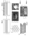
- figure 1 shows a hybrid metal/ceramic structure 6 composed of at least four layers for use in high temperature environments such as GT's.
- the structure is made of load bearing superalloy material 5, an oxidation/corrosion resistant bondcoat 4, a low temperature ceramic layer 3 resistant up to temperatures of 1150°C (may also be a multilayer structure), a ceramic adhesive layer 2 and high temperature ceramic part or layer 1, with temperature capability up to 1750°C.
- the metallic substrate 5 is a Ni-based superalloy
- the bondcoat layer 4 is composed either of a MCrAlY or PtAl system
- the low temperature ceramic layer 3 or TBC layer is based on or consists of 7YSZ
- the adhesive layer 2 is a refractory cement paste normally a calcium aluminate based.
- the high temperature resistant ceramic part 1 can be a single, multilayer or graded system prepared by processes known in the art such as vapour deposition, sol gel processes, powder deposition, direct a position, plasma spray processes and the like.
- the high temperature resistant ceramic layer 1 has a thickness of at least 2 mm and up to 20 mm, preferred thickness is between 5 and 10 mm.
- the ceramic part 1 is preferably alpha alumina based and/or magnesia based.
- the ceramic part 1 can be gas tight (closed porosity in the range of 0-10%), or have open plus closed porosity ranging from 15%-90%.
- the layered system can, as illustrated in figure 2 , have a porous layer 1b at the interface with the TBC, ensuring strain tolerance and have a dense layer 1a at the surface exposed to the combustion gases to provide erosion resistance.
- the dense outer layer 1a can be, as illustrated in figure 3a , giving a honeycomb tile structure in a top view, composed of individual tiles separated by a small gaps or intentional cracks 7 designed so as to ensure reduced matter loss in case of foreign object damage and to reduce the strains in the layer due to thermal expansion mismatch linked to the temperature gradient and the different thermal expansion coefficient in the system.
- the typical tile size being 25mm x 25mm, so as to minimize the risk of foreign object damage.
- the sidewalls of the tiles can be straight walls perpendicular to the surface plane of the substrate.
- modified structure is shown in which the sidewalls are inclined with respect to the surface plane of the substrate. This inclination, in particular if designed such that hot gases flowing across the surface cannot easily enter the slots, can be advantageous as the hot air cannot easily penetrate through the slots.
- figure 3 c showing to different interlocking sidewalls structures for the tiles, it is possible to have like labyrinth groove structures which on the one hand can increase mechanical stability and on the other hand can further prevents penetration of hot air to more hot air sensitive layers buried below the tiles.
- a first series of experiments was performed using a high grade calcium aluminate cement to join 7YSZ coating to an open-cell alpha-alumina monolithic ceramic with the porosity of about 80 percent prepared by a sol-gel process.
- the cements paste used had a solid to liquid ratio of ⁇ 60-90 wt% ( ⁇ 35-70 vol%).
- the wet cements were applied to the surfaces of the parts with a sponge.
- the cement thickness were less than 0.5mm typically in the range of or less than 0.05mm.
- the cements were dried at room temperature for 4 to 12hr in laboratory atmosphere with a compressive load from 70 to 850 g/cm2 applied perpendicular to the joint face ("wet loading").
- the load was produced by using gravity and steel plates as weights. The wet loading had a significant influence on the joint adhesion.
- the cements were cured in atmospheric box furnaces at temperature from 500 to 600°C for 5 to 15hr with a curing load of 0.0 to 250 g/cm2 applied perpendicular to the joint face. Some cements were cured in steps of 93°C for 2hr plus 260°C for 2hr plus 372°C for 2hr with a curing load of 0.0 to 250 g/cm2 applied perpendicular to the joint face. Sometimes a final curing step of 600°C for 5 hrs was used.
- the ceramic plates were cut with a low speed diamond saw or by water jet to avoid crack initiation at the cutting edges. Before joining both surfaces were abraded with SiC paper and subsequently cleaned ultrasonically in ethanol to improve adhesion of the cement.
- the sample was produced as follows:
- a NiCoCrAlY bondcoat (about 0.3mm thickness) and a 7YSZ coating layer (about 0.8mm thickness) was produced by plasma spray processes.
- a thin layer (about 0.1mm) of the refractory cement was applied manually to the surface of this TBC layer and on an open cell alpha alumina monolithic ceramic (about 20mm thickness). Subsequently both pieces were joined putting the cement layers together. After curing 24h in humid environment, assembly was heat treated with the following steps: 60°C/2h, 120°C/2h, 300°C/2h, 1000°C/20h. The heating and cooling rate for the last step was about 50K/h.
Landscapes
- Chemical & Material Sciences (AREA)
- Engineering & Computer Science (AREA)
- Materials Engineering (AREA)
- Organic Chemistry (AREA)
- Ceramic Engineering (AREA)
- Inorganic Chemistry (AREA)
- Mechanical Engineering (AREA)
- Chemical Kinetics & Catalysis (AREA)
- Metallurgy (AREA)
- Structural Engineering (AREA)
- Manufacturing & Machinery (AREA)
- Physics & Mathematics (AREA)
- Plasma & Fusion (AREA)
- General Engineering & Computer Science (AREA)
- Turbine Rotor Nozzle Sealing (AREA)
- Ceramic Products (AREA)
- Laminated Bodies (AREA)
- Coating By Spraying Or Casting (AREA)
Abstract
Description
- The present invention relates to the field of thermal barrier coatings (TBC) as used in particular for the protection of components exposed to the hot gas path of machines such as gas turbines.
- Gas turbines (GT) are increasingly requested to have higher efficiencies and this is normally achieved primarily through increase of the firing temperature up to 1750°C at least for very short periods of time and reduced cooling effort to the GT components. These components in addition to handling the high temperatures should also be able to cope with harsh GT environments for extended periods of time (operating hours > 24000h).
- There are the following main approaches to produce thermal barrier coating systems that are capable of handling high temperatures and harsh environments:
- 1. Base Metal/Bondcoat (BC)/ Thermal Barrier Coating (TBC)
- 2. Base Metal/BC/TBC/ Environmental Barrier Coating (EBC)
- 3. Ceramic matrix composites (CMC)
- a) Oxide CMC + High Temperature Insulation
- b) Non-Oxide CMC + EBC
- 4. Free standing hybrid ceramic structures such as e.g. disclosed in
US 2003/0207155 - The temperature capability Tmax of materials is defined specifically for industrial gas turbine application as the maximum possible surface temperature for 24000h in gas turbine combustion gas environment without significant loss of functionality (e.g. reduced thermal barrier effect due to spallation, strain tolerance due sintering, degradation due to environmental attack of combustion gas constituents, thermal phase stability).
- Tmax of state of the art TBC systems with about 7 wt% Yttria Stabilized Zirconia (7YSZ) have been determined to be <1150°C because of sintering behaviour which results in higher stiffness and lower strain tolerance for thermal cycling (start-stop-cycle of the turbine). Also the thermal phase stability of YSZ is limited to about 1100°C for long-term operation. Tmax for the environmental attack due to Ca-compound form the combustion gas was determined to be around 1200°C.
- As all these degradation processes are thermally activated (exponential growth of reaction rates) Tmax is defined as that temperature where significant material degradation compared to virgin material occurs.
- The quantification of degradation can be done by state of the art test and evaluation tools, e.g. X-ray diffraction, Knoop hardness, SEM, dilatometer, etc.
- The limitations of this prior art coating systems can essentially be summarised as follows:
- 1. Current BC/TBC systems that are based on MCrAlY / 7 wt% Yttria Stabilized Zirconia (7YSZ) have reached their limits in terms of both temperature capability and their ability to withstand severe GT environments. The upper temperatures of these systems are reaching their limit and are prone to attack by contaminants in the fuel such as Vanadium and environmental contaminants such as Calcium Magnesium Alumino Silicate (CMAS).
- 2. TBC/EBC systems comprised of dual/graded layers of ceramics that are functionally separated, wherein the TBC provides the temperature protection and the EBC is intended to protect the TBC from the harsh environments of the GT. These systems are still based on the conventional BC/TBC design with an additional thin coating forming the EBC layer.
- 3a. Oxide based CMCs are limited in terms of temperature capability and need to be protected with a high temperature insulating layer. The oxide based CMCs have a temperature capability of 1100°C, with the application of thermal insulating layers, Mullite (Alumino Silicate) based systems are known which are highly porous and capable of handling temperatures up to 1400°C for long term applications. They do not require an additional EBC since the CMC materials is resistant against environmental attack. Tmax seems to be limited to <1200°C for such systems due to low strain tolerance caused by sintering of fibre and matrix, resulting in insufficient thermal cycling behavior for long-term operation.
- 3b. Non-Oxide based CMC are capable of handling the highest temperatures (1600°C). However they are susceptible to attack by GT environment (specifically recession by the action of water vapor) and need to be protected with an EBC. These systems can withstand the severe GT atmospheres when protected by an EBC layer however, after more than one decade of developments, the corrosion problem is still not fully solved, since any crack in the EBC can lead to the complete failure of the component.
- Document
EP 1 806 435 discloses, on a metallic substrate, a bond coat, and on this a so-called inner layer based on a ceramic material, followed by an outer layer also based on a ceramic material. Optionally on this outermost layer additionally an alumina layer may be provided. There is no disclosure of applying prefabricated monolithic ceramic elements in the context of making such a layer structure. -
US 2006/280954 relates to layer structures on silicon containing substrates, and not on metal based substrates. There is an outermost sealing layer which may comprise calcium aluminate, and on this sealing layer there can be provided a further TBC layer. Again the document does not disclose the application of prefabricated monolithic ceramic elements in the context of making such a layer structure. - The object of the present invention is thus to provide a thermal protection system that is capable of handling high temperatures and harsh environments as will be required of future gas turbines.
- This is achieved by typically a four-layer metal/ceramic hybrid system on a metallic substrate (component, e.g. nickel-based superalloy). The system among other aspects relies on e.g. utilizing the current state of the art metal/BC/TBC systems and to augment their temperature capability by bonding a high temperature capable ceramic material able to withstand harsh GT environments to the metal/BC/TBC system.
- Specifically, the present invention relates to a multilayer thermal protection system, in which a first ceramic layer (TBC layer) is attached via a bond coat layer on a metallic substrate. On the first ceramic layer there is provided at least one second ceramic layer attached to the first ceramic layer via a ceramic adhesive layer. The first ceramic layer is normally applied by plasma spraying (or another thermal spraying method) and the second ceramic layer comprises monolithic ceramic elements adhesively attached by the ceramic adhesive layer to the first ceramic layer.
- Monolithic ceramic elements are to be understood as pre-fabricated elements which can be in the form of tiles, columnar structures, block structures or the like, what is important is that they are pre-manufactured and already sintered prior to the application to the substrate. These monolithic ceramic elements are typically sintered at temperatures of around 1600°C and therefore do not undergo a further sintering process anymore when mounted in the machine.
- Typically, the first plasma sprayed ceramic layer has a thickness in the range of 0.1 to 2 mm.
- Typically the second ceramic layer, i.e. the monolithic ceramic elements have a thickness (measured perpendicular to the surface plane of the substrate) in the range of 2 to 35mm, preferably in the range of 5-10 mm.
- According to one preferred embodiment, the first ceramic layer is a low-temperature ceramic layer and the second ceramic layer is a high temperature ceramic layer.
- This means that the first ceramic layer normally has a temperature capability Tmax up to and including a temperature of 1150°C, preferably up to and including a temperature of 1100°C, as for example the case for conventional TBC layer as outlined above.
- The second ceramic layer, i.e. the monolithic ceramic elements, Preferentially has a higher temperature capability Tmax than the first ceramic layer. This means that preferably the temperature capability Tmax of the second ceramic layer is at least 100°C, preferably at least 200°C or even 300°C, larger than the temperature capability Tmax of the first ceramic layer.
- Normally the second ceramic layer has a temperature capability Tmax of at least 1200°C, more preferably of at least 1500°C, even more preferably in the range of 1200-1750°C. Tmax of the second layer is defined by the sintering, phase stability and environmental stability.
- As outlined above, the temperature capability Tmax of materials is defined specifically for industrial gas turbine applications as the maximum possible surface temperature for 24000h in gas turbine combustion gas environment without significant loss of functionality such as reduced thermal barrier effect due to spallation, strain tolerance due sintering, degradation due to environmental attack of combustion gas constituents, thermal phase stability.
- The quantification of degradation for the determination of the temperature capability can be done by state of the art test and evaluation tools, e.g. X-ray diffraction, Knoop hardness, SEM, dilatometer, etc. as concerns the measurement of these quantities, reference is made to the following literature: ASTM C1326 - 08e1 Standard Test Method for Knoop Indentation Hardness of Advanced Ceramics; ASTM E831 Standard Test Method for Linear Thermal Expansion of Solid Materials by Thermomechanical Analysis; G.Witz, V. Shklover, W. Steurer, S. Bachegowda, H.-P. Bossmann: MONITORING THE PHASE EVOLUTION OF YTTRIA STABILIZED ZIRCONIA IN THERMAL BARRIER COATINGS USING THE RIETVELD METHOD, Journal of the American Ceramic Society, Volume 90 ).
- Using these quantities the temperature capability can be determined as described in the above mentioned publication from Witz. A time-temperature-relation was established for the temperature range 1100-1400°C for exposure times 1-1400h. The measured kinetics of phase evolution (or phase stability) was combined with the temperature dependence using the Arrhenius equation for thermally activated processes. Tmax for a certain time of exposure can be extrapolated from these data. This approach is applicable also for sintering and environmental stability. For this purpose the individual layers can be tested and investigated as stand-alone layers.
- The nature of the system ensures that the thermal mismatch between the adjacent layers is minimized to reduce internal stresses at the interfaces of the various layers.
- Metal/BC/TBC systems have a limited temperature capability, by bonding an independent ceramic part that is capable handling higher temperature and having higher environmental resistance to hot gas exposed surface of the Metal/BC/TBC system, the system can be made to operate at temperatures above 1400°C.
- The top ceramic part can be a single, multilayer or graded system prepared by any state of the art processes. This independent part is bonded to the metal/BC/TBC system. The preferred bonding method being adhesive, achieved by means of ceramic cement pastes.
- The cements paste used in this context preferably have a solid to liquid ratio of in the range of 60-90 wt% (equalling roughly 35-70 vol%).
- The present invention also relates to a method for making a multilayer thermal protection system as defined above and further below.
- The wet cements can be applied to the surfaces of the parts for example using a sponge. The cement thickness is preferably less than 0.5mm, even more preferably the cement thickness is less than 0.1 mm, or in the range of 0.05mm.
- The cements are preferably dried at room temperature for 4 to 12hr. Preferably the drying takes place under a compressive load in the range of 70 to 850 g/cm2 preferentially applied perpendicularly to the joint face ("wet loading"). The load can for example be produced by using gravity and steel plates as weights. The wet loading can have significant influences on the joint adhesion.
- The cements can be cured in atmospheric box furnaces, preferably at a temperature in the range of 500 to 600°C and more preferably within a timespan of 5 to 15h. Preferably curing takes place with a curing load of up to 250 g/cm2 applied perpendicularly to the joint face. Also a staged during protocol as possible. It is for example possible to cure cements according to yet another preferred embodiment in steps of in the range of 90-100°C for 0.5-3 h followed by curing at a temperature of 200-300°C for 0.5-3 h followed by curing at a temperature in the range of 300-400°C for 0.5-3 h with a curing load of up to 250 g/cm2 applied perpendicular to the joint face. For specific applications/materials a final curing step of a 500-700°C for 3-6 h can be used.
- According to a preferred embodiment, the second ceramic layer has a thickness in the range of 2-20 mm, preferably in the range of 5-10 mm. The second ceramic layer (but also the first ceramic layer) can be a single layer, multilayer or graded layer system.
- According to a further preferred embodiment, the second ceramic layer so the monolithic ceramic elements are alpha-alumina based and/or magnesia based, wherein preferably elements of the second ceramic layer essentially consist of alpha alumina and/or magnesia. They can be produced using methods according to the state-of-the-art, where starting from this material a green compact is produced which is subsequently sintered, normally at temperatures around 1600°C.
- The ceramic plates can be cut with a low speed diamond saw or by water jet to avoid crack initiation at the cutting edges. Before joining both surfaces can be abraded with SiC paper and subsequently cleaned ultrasonically in ethanol to improve adhesion of the cement.
- These prefabricated elements are subsequently joined to the first (TBC) layer using the adhesive, braze etc. on a TBC coated metallic substrate.
- Multilayer thermal protection system can be characterised in that the porosity of the first layer is in the range of 5-25%.
- Preferentially, second ceramic layer is a multilayer structure with at least one dense surface exposed layer with a porosity of below 30%, preferably in the range of 0-25% or 5-10%, and with at least one porous interface layer (can be of the same constitution or of a different constitution) with a porosity of above 30%, preferably in the range of 50-90%, at the interface with the first ceramic layer.
- Yet another preferred embodiment is characterised in that the second ceramic layer comprises at least one surface exposed layer and at least one underlying additional layer, and the surface exposed layer is structured as a two-dimensional array of tiles separated by gaps.
- The gaps between the tiles can be slots with parallel sidewalls perpendicular to or inclined with respect to the surface plane of the substrate. In this case the sidewalls of the tiles are planes perpendicular to the surface plane or inclined with respect to the surface plane, respectively.
- In the alternative is also possible to have sidewalls of the tiles which have an interlocking shape, such as key and slot joints or tongue and groove joints.
- The tiles structure of the most surface exposed layer allows to reduce thermal expansion problems and allows to keep local damage due to foreign object impact (FOD) to a minimum. The tiles can be of rectangular, quadratic, rhombic or hexagonal shape. Preferably, in particular in case of a regular hexagonal shape (honeycomb) the lateral extension of a tile in both dimensions is in the range of 2-35 mm, preferably in the range of 10-20 mm.
- The ceramic adhesive layer can be a refractory cement paste layer. It can be calcium aluminate based, or can even essentially consist of calcium aluminate.
- According to a preferred embodiment, the bond coat is composed of MCrAlY, where M = Co, Ni or Co/Ni, and/or of PtAl.
- Preferably the composition of the bond coat is given as 25Cr 5.5Al 2.5Si 1Ta 0.6Y with the remainder Ni, or as 12Co 20Cr 11Al 2.7Si 1Ta 0.6Y with the remainder Ni.
- As mentioned above, typically the first ceramic layer is a conventional TBC layer, and can for example be based on or consist of 7YSZ. (ZrO2, stabilised with 7 wt.-% Y2O3).
- In order to ensure mechanical bonding, grooves, ribs, anchors and roughening can be utilized. this means, that, according to a preferred embodiment, at at least one of the interfaces to the ceramic adhesive layer mechanical bonding aids are provided, preferably in the form of grooves, ribs, anchors, and/or surface texture (roughening) provided in the first ceramic layer and/or the second ceramic layer.
- Furthermore the present invention relates to the use of a thermal barrier coating layer system as outlined above for coating at least a part of a component exposed to temperatures above 1400°C.
- More specifically, it relates to the use of a thermal barrier coating layer system as outlined above for coating at least partially components exposed to the hot gas path in thermal engines, in particular in gas turbines, preferably exposed to hot gases with temperatures above 1400°C.
- Such a thermal barrier coating layer system can for example be used for selectively coating only the most temperature exposed parts of gas turbine components exposed to the hot gas path, while surrounding parts are coated with a thermal barrier coating system consisting of a thermal barrier coating layer attached to the metallic substrate by a bond coat layer.
- Further embodiments of the present invention are outlined in the dependent claims.
- Preferred embodiments of the invention are described in the following with reference to the drawings, which are for the purpose of illustrating the present preferred embodiments of the invention and not for the purpose of limiting the same. In the drawings,
- Fig. 1
- shows a schematic cut through a barrier coating according to the invention perpendicular to the plane of the component with the barrier coating according to a first embodiment;
- Fig. 2
- shows a schematic cut through a barrier coating according to the invention perpendicular to the plane of the component with the barrier coating according to a second embodiment;
- Fig. 3
- a) shows a schematic representation of a top view onto a honeycomb tile structure of the barrier coating, b) shows a schematic representation of a cut perpendicular to the plane of the substrate with planar surfaces of the sidewalls of the tiles and c) shows a schematic representation of a cut perpendicular to the plane of the substrate with interlocking surfaces of the sidewalls of the tiles;
- Fig. 4
- shows an open cell alpha-alumina joined to 7YSZ prior to exposure to thermal cycling (a) and thermal cycling of open cell alpha-alumina joined to 7YSZ during cooling down cycle; and
- Fig. 5
- shows a 20vol.% porous alpha-alumina joined to 7YSZ.
- Referring to the drawings, which are for the purpose of illustrating the present preferred embodiments of the invention and not for the purpose of limiting the same,
figure 1 shows a hybrid metal/ceramic structure 6 composed of at least four layers for use in high temperature environments such as GT's. The structure is made of load bearingsuperalloy material 5, an oxidation/corrosion resistant bondcoat 4, a lowtemperature ceramic layer 3 resistant up to temperatures of 1150°C (may also be a multilayer structure), a ceramicadhesive layer 2 and high temperature ceramic part or layer 1, with temperature capability up to 1750°C. - The
metallic substrate 5 is a Ni-based superalloy, the bondcoat layer 4 is composed either of a MCrAlY or PtAl system, the lowtemperature ceramic layer 3 or TBC layer is based on or consists of 7YSZ and theadhesive layer 2 is a refractory cement paste normally a calcium aluminate based. The high temperature resistant ceramic part 1 can be a single, multilayer or graded system prepared by processes known in the art such as vapour deposition, sol gel processes, powder deposition, direct a position, plasma spray processes and the like. The high temperature resistant ceramic layer 1 has a thickness of at least 2 mm and up to 20 mm, preferred thickness is between 5 and 10 mm. - The ceramic part 1 is preferably alpha alumina based and/or magnesia based. The ceramic part 1 can be gas tight (closed porosity in the range of 0-10%), or have open plus closed porosity ranging from 15%-90%.
- The layered system can, as illustrated in
figure 2 , have aporous layer 1b at the interface with the TBC, ensuring strain tolerance and have adense layer 1a at the surface exposed to the combustion gases to provide erosion resistance. - The dense
outer layer 1a can be, as illustrated infigure 3a , giving a honeycomb tile structure in a top view, composed of individual tiles separated by a small gaps orintentional cracks 7 designed so as to ensure reduced matter loss in case of foreign object damage and to reduce the strains in the layer due to thermal expansion mismatch linked to the temperature gradient and the different thermal expansion coefficient in the system. The typical tile size being 25mm x 25mm, so as to minimize the risk of foreign object damage. - As can be seen from
figure 3 b in the top part thereof, the sidewalls of the tiles can be straight walls perpendicular to the surface plane of the substrate. In the bottom representation offigure 3 b modified structure is shown in which the sidewalls are inclined with respect to the surface plane of the substrate. This inclination, in particular if designed such that hot gases flowing across the surface cannot easily enter the slots, can be advantageous as the hot air cannot easily penetrate through the slots. As can be see fromfigure 3 c , showing to different interlocking sidewalls structures for the tiles, it is possible to have like labyrinth groove structures which on the one hand can increase mechanical stability and on the other hand can further prevents penetration of hot air to more hot air sensitive layers buried below the tiles. - A first series of experiments was performed using a high grade calcium aluminate cement to join 7YSZ coating to an open-cell alpha-alumina monolithic ceramic with the porosity of about 80 percent prepared by a sol-gel process.
- The cements paste used had a solid to liquid ratio of ∼60-90 wt% (∼35-70 vol%). The wet cements were applied to the surfaces of the parts with a sponge. The cement thickness were less than 0.5mm typically in the range of or less than 0.05mm.
- The cements were dried at room temperature for 4 to 12hr in laboratory atmosphere with a compressive load from 70 to 850 g/cm2 applied perpendicular to the joint face ("wet loading"). The load was produced by using gravity and steel plates as weights. The wet loading had a significant influence on the joint adhesion.
- The cements were cured in atmospheric box furnaces at temperature from 500 to 600°C for 5 to 15hr with a curing load of 0.0 to 250 g/cm2 applied perpendicular to the joint face. Some cements were cured in steps of 93°C for 2hr plus 260°C for 2hr plus 372°C for 2hr with a curing load of 0.0 to 250 g/cm2 applied perpendicular to the joint face. Sometimes a final curing step of 600°C for 5 hrs was used.
- The ceramic plates were cut with a low speed diamond saw or by water jet to avoid crack initiation at the cutting edges. Before joining both surfaces were abraded with SiC paper and subsequently cleaned ultrasonically in ethanol to improve adhesion of the cement.
- On a substrate of nickel superalloy a NiCoCrAlY bondcoat (about 0.3mm thickness) and a 7YSZ coating layer (about 0.8mm thickness) was produced by plasma spray processes. A thin layer (about 0.1mm) of the refractory cement was applied manually to the surface of this TBC layer and on an open cell alpha alumina monolithic ceramic (about 20mm thickness). Subsequently both pieces were joined putting the cement layers together. After curing 24h in humid environment, assembly was heat treated with the following steps: 60°C/2h, 120°C/2h, 300°C/2h, 1000°C/20h. The heating and cooling rate for the last step was about 50K/h.
- The corresponding structure is shown in
Figure 4a . Then, the assembly was thermal cycled (23h dwell time at 1000°C and 1h dwell time at room temperature) for 2 weeks and survived as shown inFigure 4b during the cooling down cycle. - Subsequently a second series of experiments was conducted using the same substrate/Bondcoat/TBC system and the same refractory cement but as second layer 1 an alpha-alumina monolithic part with 20% porosity and 12mm thickness was used.
Grooves 9 were made on the mating surfaces of theTBC 3 and the alpha-alumina 1 in order to improve the mechanical interlocking of the cement, as shown infigure 5 . The assembly was thermal cycled for short-term duration as in the first series of experiments at elevated temperature. - The sample was produced similarly as in case of the above first series of experiments.
-
- 1
- second ceramic layer, high temperature ceramic top layer
- 1a
- dense surface exposed layer part of 1
- 1b
- porous interface layer of 1
- 2
- ceramic adhesive layer
- 3
- first ceramic layer, low-temperature ceramic layer
- 4
- bond coat layer
- 5
- metallic substrate, superalloy
- 6
- hybrid metal/ceramic structure
- 7
- gap between tiles
- 8
- honeycomb tiles
- 9
- slots in 1 and/or 3
Claims (15)
- Multilayer thermal protection system, in which a first ceramic layer (3) is attached via a bond coat layer (4) on a metallic substrate (5), wherein on the first ceramic layer (3) there is provided at least one second ceramic layer (1) attached to the first ceramic layer (3) via a ceramic adhesive layer (2), wherein the first ceramic layer (3) is applied by plasma spraying and the second ceramic layer (1) comprises monolithic ceramic elements adhesively attached to the first ceramic layer (3).
- Multilayer thermal protection system according to claim 1, wherein the monolithic ceramic elements are pre-fabricated elements selected from the group of tiles, columnar structures, block structures, or combinations thereof, wherein the pre-fabricated elements are pre-manufactured and already sintered prior to the application to the substrate (5), wherein preferably the pre-fabricated elements are sintered at temperatures of around 1600°C so as not to undergo a further sintering process anymore when mounted in the machine.
- Multilayer thermal protection system according to claim 1 or 2, wherein the first ceramic layer (3) has a thickness in the range of 0.1 to 2 mm, and wherein the second ceramic layer (1) has a thickness in the range of 2 to 35mm, preferably in the range of 5-10 mm.
- Multilayer thermal protection system according to any of the preceding claims, wherein the first ceramic layer (3) has a temperature capability (Tmax) up to and including a temperature of 1150°C, preferably up to and including a temperature of 1100°C, and wherein the second ceramic layer (1) has a higher temperature capability (Tmax) than the first ceramic layer (3), wherein preferably the temperature capability (Tmax) of the second ceramic layer (1) is at least 100°C, preferably at least 200°C, larger than the temperature capability (Tmax) of the first ceramic layer (3), wherein preferably the second ceramic layer (1) has a temperature capability (Tmax) of at least 1200°C, more preferably of at least 1500°C, even more preferably in the range of 1200-1750°C, wherein preferably the second ceramic layer (1) is a single layer, multilayer or graded layer system.
- Multilayer thermal protection system according to any of the preceding claims, wherein the second ceramic layer (1) is alpha-alumina based and/or magnesia based, wherein preferably the second ceramic layer (1) essentially consists of alpha alumina and/or magnesia.
- Multilayer thermal protection system according to any of the preceding claims, wherein the second ceramic layer (1) comprises at least one surface exposed layer (1a) and at least one underlying additional layer (1b), and wherein the surface exposed layer (1a) is structured as a two-dimensional array of tiles (8) separated by gaps (7), wherein preferably the tiles are of rectangular, quadratic, rhombic or hexagonal shape, and wherein preferably the lateral extension of a tile in both dimensions is in the range of 15-35 mm, preferably in the range of 20-30 mm, wherein further preferably the gaps (7) between the tiles (8) are slots with parallel sidewalls perpendicular to or inclined with respect to the surface plane of the substrate, or are slots with interlocking shape.
- Multilayer thermal protection system according to any of the preceding claims, wherein the ceramic adhesive layer (2) is a refractory cement paste layer, preferably calcium aluminate based, more preferably essentially consisting of calcium aluminate.
- Multilayer thermal protection system according to any of the preceding claims, wherein the metallic substrate (5) is a nickel-based superalloy.
- Multilayer thermal protection system according to any of the preceding claims, wherein the bond coat is composed of MCrAlY, where M = Co, Ni or Co/Ni, and/or is composed of PtAl, wherein preferably the composition of the bond coat is given as 25Cr 5.5Al 2.5Si 1Ta 0.6Y with the remainder Ni, or as 12Co 20Cr 11Al 2.7Si 1Ta 0.6Y with the remainder Ni.
- Multilayer thermal protection system according to any of the preceding claims, wherein the first ceramic layer (3) is based on or consists of 7YSZ.
- Multilayer thermal protection system according to any of the preceding claims, wherein at least at one interface to the ceramic adhesive layer (2) mechanical bonding aids are provided, preferably in the form of grooves, ribs, anchors, and/or surface texture provided in the bondcoat (4) and/or the first ceramic layer (3) and/or the adhesive layer (4) and/or the second ceramic layer (1).
- Method for the production of a multilayer thermal protection system according to any of the preceding claims, comprising the steps of attaching a first ceramic layer (3) via a bond coat layer (4) on a metallic substrate (5), attaching on the first ceramic layer (3) via a ceramic adhesive layer (2) at least one second ceramic layer (1), wherein the first ceramic layer (3) is applied by plasma spraying and the second ceramic layer (1) comprises monolithic ceramic elements adhesively attached to the first ceramic layer (3), wherein preferably adhesive attachment is established using a cement, and a drying this cement at room temperature for 4 to 12hr, preferably under a compressive load in the range of 70 to 850 g/cm2 applied perpendicularly to the joint face, further preferably followed by or replace/supplemented by curing at a temperature in the range of 500 to 600°C, preferably within a timespan of 5 to 15h, wherein preferably curing takes place with a curing load of up to 250 g/cm2 applied perpendicularly to the joint face.
- Use of a multilayer thermal protection system according to any of the preceding claims 1-11 for coating at least a part of a component exposed to temperatures above 1400°C.
- Use of a multilayer thermal protection system according to any of the preceding claims 1-11 for coating at least partially components exposed to the hot gas path in thermal engines, in particular in gas turbines, preferably exposed to hot gases with temperatures above 1400°C.
- Use of a thermal barrier coating layer system according to any of the preceding claims 1-11 or for selectively coating only the most temperature exposed parts of gas turbine components exposed to the hot gas path, while surrounding parts are coated with a thermal barrier coating system consisting of a thermal barrier coating layer attached to the metallic substrate (5) by a bond coat layer (4).
Priority Applications (1)
| Application Number | Priority Date | Filing Date | Title |
|---|---|---|---|
| EP10155613.2A EP2233451B1 (en) | 2009-03-27 | 2010-03-05 | Multilayer thermal protection system and its use |
Applications Claiming Priority (2)
| Application Number | Priority Date | Filing Date | Title |
|---|---|---|---|
| EP09156515A EP2233450A1 (en) | 2009-03-27 | 2009-03-27 | Multilayer thermal protection system and its use |
| EP10155613.2A EP2233451B1 (en) | 2009-03-27 | 2010-03-05 | Multilayer thermal protection system and its use |
Publications (2)
| Publication Number | Publication Date |
|---|---|
| EP2233451A1 true EP2233451A1 (en) | 2010-09-29 |
| EP2233451B1 EP2233451B1 (en) | 2013-11-20 |
Family
ID=40886842
Family Applications (2)
| Application Number | Title | Priority Date | Filing Date |
|---|---|---|---|
| EP09156515A Withdrawn EP2233450A1 (en) | 2009-03-27 | 2009-03-27 | Multilayer thermal protection system and its use |
| EP10155613.2A Not-in-force EP2233451B1 (en) | 2009-03-27 | 2010-03-05 | Multilayer thermal protection system and its use |
Family Applications Before (1)
| Application Number | Title | Priority Date | Filing Date |
|---|---|---|---|
| EP09156515A Withdrawn EP2233450A1 (en) | 2009-03-27 | 2009-03-27 | Multilayer thermal protection system and its use |
Country Status (6)
| Country | Link |
|---|---|
| US (1) | US20100247953A1 (en) |
| EP (2) | EP2233450A1 (en) |
| JP (1) | JP5709391B2 (en) |
| CN (1) | CN101845969B (en) |
| CA (1) | CA2696933C (en) |
| ES (1) | ES2448591T3 (en) |
Families Citing this family (34)
| Publication number | Priority date | Publication date | Assignee | Title |
|---|---|---|---|---|
| US20110133472A1 (en) * | 2010-04-20 | 2011-06-09 | Joerg Middendorf | Wind Turbine, Nacelle, And Method Of Assembling Wind Turbine |
| EP2431572A1 (en) * | 2010-09-21 | 2012-03-21 | Siemens Aktiengesellschaft | Thermal barrier coating for a steam turbine component |
| CN102127738B (en) * | 2010-11-25 | 2013-01-30 | 北京航空航天大学 | A kind of multi-layer thermal barrier coating and preparation method thereof |
| US20120317984A1 (en) * | 2011-06-16 | 2012-12-20 | Dierberger James A | Cell structure thermal barrier coating |
| US8739547B2 (en) * | 2011-06-23 | 2014-06-03 | United Technologies Corporation | Gas turbine engine joint having a metallic member, a CMC member, and a ceramic key |
| US9771811B2 (en) * | 2012-01-11 | 2017-09-26 | General Electric Company | Continuous fiber reinforced mesh bond coat for environmental barrier coating system |
| CN105189931B (en) * | 2013-03-15 | 2017-05-24 | 西门子能源公司 | Component repair using brazed surface textured superalloy foil |
| US9316110B2 (en) * | 2013-08-08 | 2016-04-19 | Solar Turbines Incorporated | High porosity abradable coating |
| EP2851514A1 (en) * | 2013-09-20 | 2015-03-25 | Alstom Technology Ltd | Method for applying heat resistant protection components onto a surface of a heat exposed component |
| EP2851356A1 (en) * | 2013-09-20 | 2015-03-25 | Alstom Technology Ltd | Method for producing means with thermal resist for applying at a surface of a heat exposed component |
| EP2851513A1 (en) * | 2013-09-20 | 2015-03-25 | Alstom Technology Ltd | Heat exposed component |
| US10273583B2 (en) | 2013-11-26 | 2019-04-30 | United Technologies Corporation | Gas turbine engine component coating with self-healing barrier layer |
| WO2016133987A2 (en) | 2015-02-18 | 2016-08-25 | Siemens Aktiengesellschaft | Forming cooling passages in combustion turbine superalloy castings |
| US8939706B1 (en) * | 2014-02-25 | 2015-01-27 | Siemens Energy, Inc. | Turbine abradable layer with progressive wear zone having a frangible or pixelated nib surface |
| EP3111055A2 (en) * | 2014-02-25 | 2017-01-04 | Siemens Aktiengesellschaft | Turbine component thermal barrier coating with depth-varying material properties |
| EP3029274B1 (en) * | 2014-10-30 | 2020-03-11 | United Technologies Corporation | Thermal-sprayed bonding of a ceramic structure to a substrate |
| EP3259451A1 (en) * | 2015-02-18 | 2017-12-27 | Siemens Aktiengesellschaft | Turbine component thermal barrier coating with crack isolating, cascading, multifurcated engineered groove features |
| EP3085896A1 (en) * | 2015-04-23 | 2016-10-26 | Siemens Aktiengesellschaft | Blade coating corresponding blade, manufacturing and repairing method |
| US10578014B2 (en) * | 2015-11-20 | 2020-03-03 | Tenneco Inc. | Combustion engine components with dynamic thermal insulation coating and method of making and using such a coating |
| DE102016201947A1 (en) | 2016-02-10 | 2017-08-10 | MTU Aero Engines AG | Thermal barrier coating with high corrosion resistance |
| DE102017200749A1 (en) | 2017-01-18 | 2018-07-19 | Siemens Aktiengesellschaft | Layer system with two intermediate layers and methods |
| US10968756B2 (en) | 2017-03-03 | 2021-04-06 | Raytheon Technologies Corporation | Thermal barrier coating compositions, methods of manufacture thereof and articles comprising the same |
| US11285711B2 (en) * | 2017-04-18 | 2022-03-29 | General Electric Company | Adhesion of a substrate onto a CMC component |
| US20180340687A1 (en) * | 2017-05-24 | 2018-11-29 | Siemens Aktiengesellschaft | Refractory ceramic component for a gas turbine engine |
| EP3514126A1 (en) * | 2018-01-17 | 2019-07-24 | Siemens Aktiengesellschaft | Ceramic composite material having an interconnection layer made from a molybdenum titanium carbide composite material, component, gas turbine, and method |
| DE102018202726A1 (en) * | 2018-02-22 | 2019-08-22 | MTU Aero Engines AG | Component, in particular blade, for a turbomachine with an armor double layer |
| US10969684B2 (en) * | 2019-04-03 | 2021-04-06 | General Electric Company | Protection and enhancement of thermal barrier coating by lithography |
| FR3104570B1 (en) * | 2019-12-12 | 2022-01-07 | Cie Des Arts De La Table Et De Lemail | Article comprising a base at least partially made of porcelain, a decoration and a thermal expansion gradient damper and method of manufacturing such an article. |
| CN111876721B (en) * | 2020-08-05 | 2022-08-12 | 广东省科学院新材料研究所 | Auxiliary heating device, plasma spraying device and spraying method |
| EP3995601A1 (en) * | 2020-11-04 | 2022-05-11 | Siemens Energy Global GmbH & Co. KG | Bilayer thermal barrier coatings with an advanced interface |
| JP7457633B2 (en) * | 2020-11-18 | 2024-03-28 | 株式会社東芝 | Thermal barrier coatings and heat-resistant components |
| CN112474234A (en) * | 2020-11-26 | 2021-03-12 | 安徽盈锐优材科技有限公司 | Thermal spraying insulating coating and preparation method thereof |
| KR102567698B1 (en) * | 2023-02-22 | 2023-08-18 | 영진아이엔디(주) | Plasma scrubber having insulation structure on the inner surface of the reaction chamber and method for manufacturing the same |
| CN118849544B (en) * | 2024-08-01 | 2025-09-02 | 东南大学 | Low thermal expansion sandwich panel structure for metal thermal protection systems |
Citations (6)
| Publication number | Priority date | Publication date | Assignee | Title |
|---|---|---|---|---|
| US5683761A (en) * | 1995-05-25 | 1997-11-04 | General Electric Company | Alpha alumina protective coatings for bond-coated substrates and their preparation |
| US20030207155A1 (en) | 1998-03-27 | 2003-11-06 | Siemens Westinghouse Power Corporation | Hybrid ceramic material composed of insulating and structural ceramic layers |
| US20040076810A1 (en) * | 2002-10-17 | 2004-04-22 | Ucar Carbon Company Inc. | Composite high temperature insulator |
| EP1674663A2 (en) * | 2004-12-14 | 2006-06-28 | Mitsubishi Heavy Industries, Ltd. | Thermal barrier coating material, thermal barrier member, and member coated with thermal barrier and method for manufacturing the same |
| US20060280954A1 (en) | 2005-06-13 | 2006-12-14 | Irene Spitsberg | Corrosion resistant sealant for outer EBL of silicon-containing substrate and processes for preparing same |
| EP1806435A2 (en) | 2006-01-06 | 2007-07-11 | General Electric Company | Layered thermal barrier coatings containing lanthanide series oxides for improved resistance to CMAS degradation |
Family Cites Families (13)
| Publication number | Priority date | Publication date | Assignee | Title |
|---|---|---|---|---|
| JPS594824A (en) * | 1982-06-29 | 1984-01-11 | Toshiba Corp | Structure of hot gas turbine combustor unit |
| JPH0718530B2 (en) * | 1986-12-22 | 1995-03-06 | ノートン カンパニー | Fireproof shield |
| US5630314A (en) * | 1992-09-10 | 1997-05-20 | Hitachi, Ltd. | Thermal stress relaxation type ceramic coated heat-resistant element |
| US6455167B1 (en) * | 1999-07-02 | 2002-09-24 | General Electric Company | Coating system utilizing an oxide diffusion barrier for improved performance and repair capability |
| DE10056617C2 (en) * | 2000-11-15 | 2002-12-12 | Forschungszentrum Juelich Gmbh | Material for temperature-stressed substrates |
| JP2003120205A (en) * | 2001-10-10 | 2003-04-23 | Toshiba Corp | Turbine blade |
| US20030152814A1 (en) * | 2002-02-11 | 2003-08-14 | Dinesh Gupta | Hybrid thermal barrier coating and method of making the same |
| US20050202168A1 (en) * | 2002-08-16 | 2005-09-15 | General Electric Company | Thermally-stabilized thermal barrier coating and process therefor |
| US7198860B2 (en) * | 2003-04-25 | 2007-04-03 | Siemens Power Generation, Inc. | Ceramic tile insulation for gas turbine component |
| US7291403B2 (en) * | 2004-02-03 | 2007-11-06 | General Electric Company | Thermal barrier coating system |
| JP4969094B2 (en) * | 2004-12-14 | 2012-07-04 | 三菱重工業株式会社 | Thermal barrier coating member and production thereof, and gas turbine |
| US7833586B2 (en) * | 2007-10-24 | 2010-11-16 | General Electric Company | Alumina-based protective coatings for thermal barrier coatings |
| US20090252985A1 (en) * | 2008-04-08 | 2009-10-08 | Bangalore Nagaraj | Thermal barrier coating system and coating methods for gas turbine engine shroud |
-
2009
- 2009-03-27 EP EP09156515A patent/EP2233450A1/en not_active Withdrawn
-
2010
- 2010-03-05 ES ES10155613.2T patent/ES2448591T3/en active Active
- 2010-03-05 EP EP10155613.2A patent/EP2233451B1/en not_active Not-in-force
- 2010-03-12 US US12/723,559 patent/US20100247953A1/en not_active Abandoned
- 2010-03-16 CA CA2696933A patent/CA2696933C/en not_active Expired - Fee Related
- 2010-03-26 CN CN201010170938.XA patent/CN101845969B/en not_active Expired - Fee Related
- 2010-03-26 JP JP2010071443A patent/JP5709391B2/en not_active Expired - Fee Related
Patent Citations (6)
| Publication number | Priority date | Publication date | Assignee | Title |
|---|---|---|---|---|
| US5683761A (en) * | 1995-05-25 | 1997-11-04 | General Electric Company | Alpha alumina protective coatings for bond-coated substrates and their preparation |
| US20030207155A1 (en) | 1998-03-27 | 2003-11-06 | Siemens Westinghouse Power Corporation | Hybrid ceramic material composed of insulating and structural ceramic layers |
| US20040076810A1 (en) * | 2002-10-17 | 2004-04-22 | Ucar Carbon Company Inc. | Composite high temperature insulator |
| EP1674663A2 (en) * | 2004-12-14 | 2006-06-28 | Mitsubishi Heavy Industries, Ltd. | Thermal barrier coating material, thermal barrier member, and member coated with thermal barrier and method for manufacturing the same |
| US20060280954A1 (en) | 2005-06-13 | 2006-12-14 | Irene Spitsberg | Corrosion resistant sealant for outer EBL of silicon-containing substrate and processes for preparing same |
| EP1806435A2 (en) | 2006-01-06 | 2007-07-11 | General Electric Company | Layered thermal barrier coatings containing lanthanide series oxides for improved resistance to CMAS degradation |
Non-Patent Citations (1)
| Title |
|---|
| G.WITZ; V. SHKLOVER; W. STEURER; S. BACHEGOWDA; H.-P. BOSSMANN: "MONITORING THE PHASE EVOLUTION OF YTTRIA STABILIZED ZIRCONIA IN THERMAL BARRIER COATINGS USING THE RIETVELD METHOD", JOURNAL OF THE AMERICAN CERAMIC SOCIETY, vol. 90, no. 9, 2007, pages 2935 - 2940 |
Also Published As
| Publication number | Publication date |
|---|---|
| EP2233451B1 (en) | 2013-11-20 |
| CA2696933C (en) | 2016-03-15 |
| ES2448591T3 (en) | 2014-03-14 |
| US20100247953A1 (en) | 2010-09-30 |
| CN101845969B (en) | 2015-07-29 |
| CA2696933A1 (en) | 2010-09-27 |
| JP2010229026A (en) | 2010-10-14 |
| JP5709391B2 (en) | 2015-04-30 |
| CN101845969A (en) | 2010-09-29 |
| EP2233450A1 (en) | 2010-09-29 |
Similar Documents
| Publication | Publication Date | Title |
|---|---|---|
| EP2233451B1 (en) | Multilayer thermal protection system and its use | |
| US7374825B2 (en) | Protection of thermal barrier coating by an impermeable barrier coating | |
| US6165600A (en) | Gas turbine engine component having a thermal-insulating multilayer ceramic coating | |
| CA2708940C (en) | Methods for repairing barrier coatings | |
| US7955707B2 (en) | High purity ceramic abradable coatings | |
| US7449254B2 (en) | Environmental barrier coating with physical barrier layer for silicon-comprising materials | |
| US7198860B2 (en) | Ceramic tile insulation for gas turbine component | |
| CN102732883B (en) | A kind of dispersed precious metal particle toughened composite thermal barrier coating and its preparation method | |
| JP7232295B2 (en) | Adhesion-promoting layer for bonding high-temperature protective layer onto substrate, and method for producing same | |
| US20090162556A1 (en) | Methods for making tape cast barrier coatings, components comprising the same and tapes made according to the same | |
| RU2741491C2 (en) | Part with applied thermal barrier for gas turbine engine and method of its production | |
| JP2009149489A (en) | Method for improving inspection of parts having a barrier coating | |
| JP2009149491A (en) | Barrier coating including taggant and parts having the same | |
| JP2009149492A (en) | Barrier coating containing taggant and method of manufacturing part having the same | |
| JP2011507789A (en) | Tape comprising barrier coating composition and component comprising the same | |
| CN112756232A (en) | Repair coating system and method | |
| US20100260960A1 (en) | Damage tolerant gas turbine component | |
| CN108138329A (en) | Apply turbine engine components, manufacture and the method using the component of protective ceramic coating | |
| EP4520850A1 (en) | Rare earth-phosphate-enhanced thermal barrier coating | |
| WO2019005121A1 (en) | Intermediate layer for added thermal protection and adhesion of a thermal barrier layer to a ceramic matrix composite substrate | |
| EP2851513A1 (en) | Heat exposed component | |
| EP2851356A1 (en) | Method for producing means with thermal resist for applying at a surface of a heat exposed component |
Legal Events
| Date | Code | Title | Description |
|---|---|---|---|
| PUAI | Public reference made under article 153(3) epc to a published international application that has entered the european phase |
Free format text: ORIGINAL CODE: 0009012 |
|
| AK | Designated contracting states |
Kind code of ref document: A1 Designated state(s): AT BE BG CH CY CZ DE DK EE ES FI FR GB GR HR HU IE IS IT LI LT LU LV MC MK MT NL NO PL PT RO SE SI SK SM TR |
|
| AX | Request for extension of the european patent |
Extension state: AL BA ME RS |
|
| 17P | Request for examination filed |
Effective date: 20110328 |
|
| 17Q | First examination report despatched |
Effective date: 20121217 |
|
| GRAP | Despatch of communication of intention to grant a patent |
Free format text: ORIGINAL CODE: EPIDOSNIGR1 |
|
| INTG | Intention to grant announced |
Effective date: 20130614 |
|
| GRAS | Grant fee paid |
Free format text: ORIGINAL CODE: EPIDOSNIGR3 |
|
| GRAA | (expected) grant |
Free format text: ORIGINAL CODE: 0009210 |
|
| AK | Designated contracting states |
Kind code of ref document: B1 Designated state(s): AT BE BG CH CY CZ DE DK EE ES FI FR GB GR HR HU IE IS IT LI LT LU LV MC MK MT NL NO PL PT RO SE SI SK SM TR |
|
| REG | Reference to a national code |
Ref country code: GB Ref legal event code: FG4D |
|
| REG | Reference to a national code |
Ref country code: CH Ref legal event code: EP |
|
| REG | Reference to a national code |
Ref country code: AT Ref legal event code: REF Ref document number: 641505 Country of ref document: AT Kind code of ref document: T Effective date: 20131215 |
|
| REG | Reference to a national code |
Ref country code: IE Ref legal event code: FG4D |
|
| REG | Reference to a national code |
Ref country code: DE Ref legal event code: R096 Ref document number: 602010011809 Country of ref document: DE Effective date: 20140116 |
|
| REG | Reference to a national code |
Ref country code: NL Ref legal event code: VDEP Effective date: 20131120 |
|
| REG | Reference to a national code |
Ref country code: ES Ref legal event code: FG2A Ref document number: 2448591 Country of ref document: ES Kind code of ref document: T3 Effective date: 20140314 |
|
| REG | Reference to a national code |
Ref country code: AT Ref legal event code: MK05 Ref document number: 641505 Country of ref document: AT Kind code of ref document: T Effective date: 20131120 |
|
| REG | Reference to a national code |
Ref country code: LT Ref legal event code: MG4D |
|
| PG25 | Lapsed in a contracting state [announced via postgrant information from national office to epo] |
Ref country code: NO Free format text: LAPSE BECAUSE OF FAILURE TO SUBMIT A TRANSLATION OF THE DESCRIPTION OR TO PAY THE FEE WITHIN THE PRESCRIBED TIME-LIMIT Effective date: 20140220 Ref country code: LT Free format text: LAPSE BECAUSE OF FAILURE TO SUBMIT A TRANSLATION OF THE DESCRIPTION OR TO PAY THE FEE WITHIN THE PRESCRIBED TIME-LIMIT Effective date: 20131120 Ref country code: SE Free format text: LAPSE BECAUSE OF FAILURE TO SUBMIT A TRANSLATION OF THE DESCRIPTION OR TO PAY THE FEE WITHIN THE PRESCRIBED TIME-LIMIT Effective date: 20131120 Ref country code: IS Free format text: LAPSE BECAUSE OF FAILURE TO SUBMIT A TRANSLATION OF THE DESCRIPTION OR TO PAY THE FEE WITHIN THE PRESCRIBED TIME-LIMIT Effective date: 20140320 Ref country code: HR Free format text: LAPSE BECAUSE OF FAILURE TO SUBMIT A TRANSLATION OF THE DESCRIPTION OR TO PAY THE FEE WITHIN THE PRESCRIBED TIME-LIMIT Effective date: 20131120 Ref country code: NL Free format text: LAPSE BECAUSE OF FAILURE TO SUBMIT A TRANSLATION OF THE DESCRIPTION OR TO PAY THE FEE WITHIN THE PRESCRIBED TIME-LIMIT Effective date: 20131120 Ref country code: FI Free format text: LAPSE BECAUSE OF FAILURE TO SUBMIT A TRANSLATION OF THE DESCRIPTION OR TO PAY THE FEE WITHIN THE PRESCRIBED TIME-LIMIT Effective date: 20131120 |
|
| PG25 | Lapsed in a contracting state [announced via postgrant information from national office to epo] |
Ref country code: BE Free format text: LAPSE BECAUSE OF FAILURE TO SUBMIT A TRANSLATION OF THE DESCRIPTION OR TO PAY THE FEE WITHIN THE PRESCRIBED TIME-LIMIT Effective date: 20131120 Ref country code: AT Free format text: LAPSE BECAUSE OF FAILURE TO SUBMIT A TRANSLATION OF THE DESCRIPTION OR TO PAY THE FEE WITHIN THE PRESCRIBED TIME-LIMIT Effective date: 20131120 Ref country code: LV Free format text: LAPSE BECAUSE OF FAILURE TO SUBMIT A TRANSLATION OF THE DESCRIPTION OR TO PAY THE FEE WITHIN THE PRESCRIBED TIME-LIMIT Effective date: 20131120 |
|
| PG25 | Lapsed in a contracting state [announced via postgrant information from national office to epo] |
Ref country code: PT Free format text: LAPSE BECAUSE OF FAILURE TO SUBMIT A TRANSLATION OF THE DESCRIPTION OR TO PAY THE FEE WITHIN THE PRESCRIBED TIME-LIMIT Effective date: 20140320 |
|
| PG25 | Lapsed in a contracting state [announced via postgrant information from national office to epo] |
Ref country code: EE Free format text: LAPSE BECAUSE OF FAILURE TO SUBMIT A TRANSLATION OF THE DESCRIPTION OR TO PAY THE FEE WITHIN THE PRESCRIBED TIME-LIMIT Effective date: 20131120 |
|
| REG | Reference to a national code |
Ref country code: DE Ref legal event code: R097 Ref document number: 602010011809 Country of ref document: DE |
|
| PG25 | Lapsed in a contracting state [announced via postgrant information from national office to epo] |
Ref country code: CZ Free format text: LAPSE BECAUSE OF FAILURE TO SUBMIT A TRANSLATION OF THE DESCRIPTION OR TO PAY THE FEE WITHIN THE PRESCRIBED TIME-LIMIT Effective date: 20131120 Ref country code: SK Free format text: LAPSE BECAUSE OF FAILURE TO SUBMIT A TRANSLATION OF THE DESCRIPTION OR TO PAY THE FEE WITHIN THE PRESCRIBED TIME-LIMIT Effective date: 20131120 Ref country code: RO Free format text: LAPSE BECAUSE OF FAILURE TO SUBMIT A TRANSLATION OF THE DESCRIPTION OR TO PAY THE FEE WITHIN THE PRESCRIBED TIME-LIMIT Effective date: 20131120 Ref country code: PL Free format text: LAPSE BECAUSE OF FAILURE TO SUBMIT A TRANSLATION OF THE DESCRIPTION OR TO PAY THE FEE WITHIN THE PRESCRIBED TIME-LIMIT Effective date: 20131120 |
|
| PLBE | No opposition filed within time limit |
Free format text: ORIGINAL CODE: 0009261 |
|
| STAA | Information on the status of an ep patent application or granted ep patent |
Free format text: STATUS: NO OPPOSITION FILED WITHIN TIME LIMIT |
|
| PG25 | Lapsed in a contracting state [announced via postgrant information from national office to epo] |
Ref country code: DK Free format text: LAPSE BECAUSE OF FAILURE TO SUBMIT A TRANSLATION OF THE DESCRIPTION OR TO PAY THE FEE WITHIN THE PRESCRIBED TIME-LIMIT Effective date: 20131120 |
|
| 26N | No opposition filed |
Effective date: 20140821 |
|
| PG25 | Lapsed in a contracting state [announced via postgrant information from national office to epo] |
Ref country code: LU Free format text: LAPSE BECAUSE OF FAILURE TO SUBMIT A TRANSLATION OF THE DESCRIPTION OR TO PAY THE FEE WITHIN THE PRESCRIBED TIME-LIMIT Effective date: 20140305 |
|
| REG | Reference to a national code |
Ref country code: CH Ref legal event code: PL |
|
| REG | Reference to a national code |
Ref country code: DE Ref legal event code: R097 Ref document number: 602010011809 Country of ref document: DE Effective date: 20140821 |
|
| REG | Reference to a national code |
Ref country code: IE Ref legal event code: MM4A |
|
| PG25 | Lapsed in a contracting state [announced via postgrant information from national office to epo] |
Ref country code: LI Free format text: LAPSE BECAUSE OF NON-PAYMENT OF DUE FEES Effective date: 20140331 Ref country code: CH Free format text: LAPSE BECAUSE OF NON-PAYMENT OF DUE FEES Effective date: 20140331 Ref country code: IE Free format text: LAPSE BECAUSE OF NON-PAYMENT OF DUE FEES Effective date: 20140305 |
|
| PG25 | Lapsed in a contracting state [announced via postgrant information from national office to epo] |
Ref country code: SI Free format text: LAPSE BECAUSE OF FAILURE TO SUBMIT A TRANSLATION OF THE DESCRIPTION OR TO PAY THE FEE WITHIN THE PRESCRIBED TIME-LIMIT Effective date: 20131120 |
|
| PG25 | Lapsed in a contracting state [announced via postgrant information from national office to epo] |
Ref country code: MT Free format text: LAPSE BECAUSE OF FAILURE TO SUBMIT A TRANSLATION OF THE DESCRIPTION OR TO PAY THE FEE WITHIN THE PRESCRIBED TIME-LIMIT Effective date: 20131120 |
|
| REG | Reference to a national code |
Ref country code: FR Ref legal event code: PLFP Year of fee payment: 7 |
|
| PG25 | Lapsed in a contracting state [announced via postgrant information from national office to epo] |
Ref country code: SM Free format text: LAPSE BECAUSE OF FAILURE TO SUBMIT A TRANSLATION OF THE DESCRIPTION OR TO PAY THE FEE WITHIN THE PRESCRIBED TIME-LIMIT Effective date: 20131120 |
|
| PG25 | Lapsed in a contracting state [announced via postgrant information from national office to epo] |
Ref country code: MC Free format text: LAPSE BECAUSE OF FAILURE TO SUBMIT A TRANSLATION OF THE DESCRIPTION OR TO PAY THE FEE WITHIN THE PRESCRIBED TIME-LIMIT Effective date: 20131120 |
|
| PG25 | Lapsed in a contracting state [announced via postgrant information from national office to epo] |
Ref country code: CY Free format text: LAPSE BECAUSE OF FAILURE TO SUBMIT A TRANSLATION OF THE DESCRIPTION OR TO PAY THE FEE WITHIN THE PRESCRIBED TIME-LIMIT Effective date: 20131120 Ref country code: BG Free format text: LAPSE BECAUSE OF FAILURE TO SUBMIT A TRANSLATION OF THE DESCRIPTION OR TO PAY THE FEE WITHIN THE PRESCRIBED TIME-LIMIT Effective date: 20131120 Ref country code: GR Free format text: LAPSE BECAUSE OF FAILURE TO SUBMIT A TRANSLATION OF THE DESCRIPTION OR TO PAY THE FEE WITHIN THE PRESCRIBED TIME-LIMIT Effective date: 20140221 |
|
| PG25 | Lapsed in a contracting state [announced via postgrant information from national office to epo] |
Ref country code: HU Free format text: LAPSE BECAUSE OF FAILURE TO SUBMIT A TRANSLATION OF THE DESCRIPTION OR TO PAY THE FEE WITHIN THE PRESCRIBED TIME-LIMIT; INVALID AB INITIO Effective date: 20100305 Ref country code: TR Free format text: LAPSE BECAUSE OF FAILURE TO SUBMIT A TRANSLATION OF THE DESCRIPTION OR TO PAY THE FEE WITHIN THE PRESCRIBED TIME-LIMIT Effective date: 20131120 |
|
| REG | Reference to a national code |
Ref country code: DE Ref legal event code: R081 Ref document number: 602010011809 Country of ref document: DE Owner name: GENERAL ELECTRIC TECHNOLOGY GMBH, CH Free format text: FORMER OWNER: ALSTOM TECHNOLOGY LTD., BADEN, CH Ref country code: DE Ref legal event code: R081 Ref document number: 602010011809 Country of ref document: DE Owner name: ANSALDO ENERGIA IP UK LIMITED, GB Free format text: FORMER OWNER: ALSTOM TECHNOLOGY LTD., BADEN, CH |
|
| REG | Reference to a national code |
Ref country code: ES Ref legal event code: PC2A Owner name: GENERAL ELECTRIC TECHNOLOGY GMBH Effective date: 20161021 |
|
| REG | Reference to a national code |
Ref country code: FR Ref legal event code: CD Owner name: ALSTOM TECHNOLOGY LTD, CH Effective date: 20161110 |
|
| REG | Reference to a national code |
Ref country code: FR Ref legal event code: PLFP Year of fee payment: 8 |
|
| PGFP | Annual fee paid to national office [announced via postgrant information from national office to epo] |
Ref country code: DE Payment date: 20170322 Year of fee payment: 8 Ref country code: FR Payment date: 20170322 Year of fee payment: 8 |
|
| PGFP | Annual fee paid to national office [announced via postgrant information from national office to epo] |
Ref country code: GB Payment date: 20170322 Year of fee payment: 8 |
|
| PGFP | Annual fee paid to national office [announced via postgrant information from national office to epo] |
Ref country code: ES Payment date: 20170315 Year of fee payment: 8 |
|
| PGFP | Annual fee paid to national office [announced via postgrant information from national office to epo] |
Ref country code: IT Payment date: 20170323 Year of fee payment: 8 |
|
| REG | Reference to a national code |
Ref country code: DE Ref legal event code: R081 Ref document number: 602010011809 Country of ref document: DE Owner name: ANSALDO ENERGIA IP UK LIMITED, GB Free format text: FORMER OWNER: GENERAL ELECTRIC TECHNOLOGY GMBH, BADEN, CH |
|
| REG | Reference to a national code |
Ref country code: GB Ref legal event code: 732E Free format text: REGISTERED BETWEEN 20170824 AND 20170830 |
|
| REG | Reference to a national code |
Ref country code: ES Ref legal event code: PC2A Owner name: ANSALDO ENERGIA IP UK LIMITED Effective date: 20170927 |
|
| REG | Reference to a national code |
Ref country code: FR Ref legal event code: TP Owner name: ANSALDO ENERGIA IP UK LIMITED, GB Effective date: 20171221 |
|
| PG25 | Lapsed in a contracting state [announced via postgrant information from national office to epo] |
Ref country code: MK Free format text: LAPSE BECAUSE OF FAILURE TO SUBMIT A TRANSLATION OF THE DESCRIPTION OR TO PAY THE FEE WITHIN THE PRESCRIBED TIME-LIMIT Effective date: 20131120 |
|
| REG | Reference to a national code |
Ref country code: DE Ref legal event code: R119 Ref document number: 602010011809 Country of ref document: DE |
|
| GBPC | Gb: european patent ceased through non-payment of renewal fee |
Effective date: 20180305 |
|
| PG25 | Lapsed in a contracting state [announced via postgrant information from national office to epo] |
Ref country code: DE Free format text: LAPSE BECAUSE OF NON-PAYMENT OF DUE FEES Effective date: 20181002 |
|
| PG25 | Lapsed in a contracting state [announced via postgrant information from national office to epo] |
Ref country code: GB Free format text: LAPSE BECAUSE OF NON-PAYMENT OF DUE FEES Effective date: 20180305 Ref country code: IT Free format text: LAPSE BECAUSE OF NON-PAYMENT OF DUE FEES Effective date: 20180305 |
|
| PG25 | Lapsed in a contracting state [announced via postgrant information from national office to epo] |
Ref country code: FR Free format text: LAPSE BECAUSE OF NON-PAYMENT OF DUE FEES Effective date: 20180331 |
|
| REG | Reference to a national code |
Ref country code: ES Ref legal event code: FD2A Effective date: 20190903 |
|
| PG25 | Lapsed in a contracting state [announced via postgrant information from national office to epo] |
Ref country code: ES Free format text: LAPSE BECAUSE OF NON-PAYMENT OF DUE FEES Effective date: 20180306 |