EP2233375A1 - Windshield wiper blade structure - Google Patents
Windshield wiper blade structure Download PDFInfo
- Publication number
- EP2233375A1 EP2233375A1 EP09156212A EP09156212A EP2233375A1 EP 2233375 A1 EP2233375 A1 EP 2233375A1 EP 09156212 A EP09156212 A EP 09156212A EP 09156212 A EP09156212 A EP 09156212A EP 2233375 A1 EP2233375 A1 EP 2233375A1
- Authority
- EP
- European Patent Office
- Prior art keywords
- strip
- support strip
- elastic arms
- elastic
- support
- Prior art date
- Legal status (The legal status is an assumption and is not a legal conclusion. Google has not performed a legal analysis and makes no representation as to the accuracy of the status listed.)
- Granted
Links
- 230000001681 protective effect Effects 0.000 description 11
- 239000000463 material Substances 0.000 description 4
- 238000003780 insertion Methods 0.000 description 3
- 230000037431 insertion Effects 0.000 description 3
- 238000012423 maintenance Methods 0.000 description 2
- XLYOFNOQVPJJNP-UHFFFAOYSA-N water Substances O XLYOFNOQVPJJNP-UHFFFAOYSA-N 0.000 description 2
- 230000007797 corrosion Effects 0.000 description 1
- 238000005260 corrosion Methods 0.000 description 1
- 239000000428 dust Substances 0.000 description 1
- 230000009545 invasion Effects 0.000 description 1
- JEIPFZHSYJVQDO-UHFFFAOYSA-N iron(III) oxide Inorganic materials O=[Fe]O[Fe]=O JEIPFZHSYJVQDO-UHFFFAOYSA-N 0.000 description 1
- 238000012986 modification Methods 0.000 description 1
- 230000004048 modification Effects 0.000 description 1
- 238000004080 punching Methods 0.000 description 1
Images


Classifications
-
- B—PERFORMING OPERATIONS; TRANSPORTING
- B60—VEHICLES IN GENERAL
- B60S—SERVICING, CLEANING, REPAIRING, SUPPORTING, LIFTING, OR MANOEUVRING OF VEHICLES, NOT OTHERWISE PROVIDED FOR
- B60S1/00—Cleaning of vehicles
- B60S1/02—Cleaning windscreens, windows or optical devices
- B60S1/04—Wipers or the like, e.g. scrapers
- B60S1/32—Wipers or the like, e.g. scrapers characterised by constructional features of wiper blade arms or blades
- B60S1/38—Wiper blades
- B60S1/3848—Flat-type wiper blade, i.e. without harness
- B60S1/3886—End caps
- B60S1/3887—Mounting of end caps
-
- B—PERFORMING OPERATIONS; TRANSPORTING
- B60—VEHICLES IN GENERAL
- B60S—SERVICING, CLEANING, REPAIRING, SUPPORTING, LIFTING, OR MANOEUVRING OF VEHICLES, NOT OTHERWISE PROVIDED FOR
- B60S1/00—Cleaning of vehicles
- B60S1/02—Cleaning windscreens, windows or optical devices
- B60S1/04—Wipers or the like, e.g. scrapers
- B60S1/32—Wipers or the like, e.g. scrapers characterised by constructional features of wiper blade arms or blades
- B60S1/38—Wiper blades
- B60S1/3848—Flat-type wiper blade, i.e. without harness
- B60S1/3874—Flat-type wiper blade, i.e. without harness with a reinforcing vertebra
- B60S1/3875—Flat-type wiper blade, i.e. without harness with a reinforcing vertebra rectangular section
- B60S1/3879—Flat-type wiper blade, i.e. without harness with a reinforcing vertebra rectangular section placed in side grooves in the squeegee
Definitions
- the present invention relates to a windshield wiper blade structure, and more particularly to a windshield wiper blade structure that allows a user to easily replace a wiper strip thereof with a new one.
- a windshield wiper structure is usually installed close to a windshield of a motor vehicle, and a wiper blade thereof is driven to swing back and forth within a generally sector-shaped wiping area.
- the wiper blade has a wiper strip made of a rubber material for wiping off deposited dust or water, such as wiping accumulated rainwater or snow from the windshield.
- the wiper strip 13 After having been swung back and forth on the windshield to wipe off rainwater or snow over a long period of time, the wiper strip 13 tends to become deformed or damaged due to elastic fatigue and must be replaced with a new one.
- the end caps 14 are not detachable from the support strip 11 once they are engaged with the elastic hooking portions 111.
- the wiper strip 13 can be removed from the support strip 11 only when the end caps 14 and the elastic hooking portions 111 are destroyed to separate the end caps 14 from the ends of the support strip 11. That is, when the wiper strip 13 is aged or damaged, the whole set of the conventional windshield wiper blade structure must be replaced. This is of course not economical to do so.
- the support strip 11 is made of a relatively tough material and has a relatively large thickness, it is uneasy to punch the support strip 11 at two ends thereof to form the two elastic hooking portions 111.
- the conventional windshield wiper blade structure is manufactured at increased cost.
- the windshield wiper blade structure includes a support strip; a wiper strip being disposed on a first face of the support strip; a set of wind deflector strips being disposed on a second face of the support strip opposite to the wiper strip; and a binding component.
- the binding component can be compressed to deform, so as to be fitted to two longitudinally opposite ends of the support strip, and the binding component can be then released to restore to its original state and become locked to the two longitudinally opposite ends of the support strip.
- the windshield wiper blade structure includes a support strip being formed with a plurality of holes; a wiper strip being disposed on a first face of the support strip; a set of flexible strips being set on two opposite lateral sides of the wiper strip; a set of clamping elements being extended through the plurality of holes on the support strip to thereby clamp the support strip, the flexible strips and the wiper strip together to form an integral body; a set of wind deflector strips being disposed on a second face of the support strip opposite to the wiper strip; and a binding component.
- the binding component can be compressed to deform, so as to be fitted to two longitudinally opposite ends of the support strip, and the binding component can be then released to restore to its original state and become locked to the two longitudinally opposite ends of the support strip.
- the binding component includes a pair of elastic locking elements and a pair of end caps.
- Each of the elastic locking elements includes a pair of elastic arms being fixed to two opposite lateral sides of the support strip near one of the two longitudinally opposite ends of the support strip, and each of the end caps is configured for detachably connecting to one of the two longitudinally opposite ends of the support strip.
- the windshield wiper blade structure includes a set of support strips, a wiper strip, a set of wind deflector strips, a set of elastic locking elements, and a set of end caps.
- the wiper strip is provided at two opposite lateral sides with a plurality of grooves each, and the set of support strips is set in two oppositely corresponding grooves.
- the set of wind deflector strips is disposed on one face of the support strips.
- Each of the elastic locking elements includes two elastic arms, and is fixed to one of two longitudinally opposite ends of the set of support strips.
- Each of the end caps is internally provided with two notches corresponding to the two elastic arms of the elastic locking element, and is detachably fitted to one of the two longitudinally opposite ends of the set of support strips.
- the windshield wiper blade structure includes a support strip, a wiper strip, a set of wind deflector strips, a set of elastic locking elements, and a set of end caps.
- the wiper strip is disposed on one face of the support strip, and the set of wind deflector strips is disposed on another face of the support strip opposite to the wiper strip.
- Each of the elastic locking elements includes two elastic arms, and is fixed to one of two longitudinally opposite ends of the support strip.
- Each of the end caps is internally provided with two notches corresponding to the two elastic arms of one elastic locking element.
- the support strip is provided with a long slit, an end of which extends through one end of the support strip to form an open end, and the other end of the long slit extends toward the other end of the support strip without extending therethrough, so that a stopper portion is formed at the other end of the support strip.
- the end caps can be connected to or removed from two longitudinally opposite ends of the support strip simply by compressing the two elastic arms on each of the elastic locking elements toward each other and then releasing the two elastic arms, enabling a user to easily remove the damaged or aged wiper strip from the support strip for replacement without the need of discarding a whole set of the windshield wiper blade structure. Therefore, the maintenance and repair cost can be reduced.
- the windshield wiper blade structure in the first embodiment includes a support strip 21, a wiper strip 22, two flexible strips 23, a plurality of clamping elements 24, two wind deflector strips 25, a binding component 260, a bracket 28, and a protective cover 29.
- the binding component 260 includes two elastic locking elements 26 and two end caps 27.
- the support strip 21 is formed with a plurality of pairs of holes 211 and two notched sections 212.
- the pairs of holes 211 are axially equally spaced along the support strip 21 and the holes in each of the pairs are arranged side by side on the support strip 21.
- the wiper strip 22 is located below the support strip 21, and includes an elongate top plate 221 for bearing against the support strip 21, a plurality of longitudinally extended grooves 222 correspondingly formed on each of two opposite lateral sides thereof, and a wiping lip 223 located opposite to the top plate 221.
- the two flexible strips 23 are separately set in two oppositely corresponding grooves 222 on the wiper strip 22.
- Each of the clamping elements 24 has two downward extended lateral sides to provide two L-shaped clamping arms 241.
- the two wind deflector strips 25 each have a wind deflecting section 251. Two opposite parallel edges of the wind deflecting section 251 are downward and then inward bent toward each other to form two guide rails 252, such that a slide way 253 is defined between the wind deflecting section 251 and the two guide rails 252.
- the support strip 21 can be slid along the guide rails 252 into the slide way 253, so that the wind deflector strip 25 is held to a top of the support strip 21.
- the elastic locking elements 26 each have two downward extended elastic arms 261 separately formed at two opposite lateral sides thereof, and are separately fitted in the two notched sections 212 on the support strip 21.
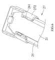
- Fig. 5 is a perspective view showing an inner structure of a first embodiment of the end caps 27.
- each of the end caps 27 has a main body 271 and a shell 272 covering the main body 271.
- Two opposite lateral sides of the shell 272 are downward and inward bent toward each other, and two notches 275 are separately formed at free edges of the inward bent lateral sides of the shell 272 corresponding to the elastic arms 261 of the elastic locking element 26.
- a space 274 is formed between each of two lateral sides of the main body 271 and the shell 272.
- Each of the two spaces 274 is slightly larger than a thickness of the elastic arm 261, so that the elastic arms 261 of the elastic locking element 26 can pass through the spaces 274.
- the two elastic arms 261 on the elastic locking element 26 can be compressed toward each other or be released to elastically expand outward.
- the bracket 28 is disposed on the top of the support strip 21 to locate between the two wind deflector strips 25 for a wiper arm (not shown) to pivotally connect thereto, so that the wiper arm can drive the bracket 28 to move reciprocatingly.
- the protective cover 29 is fitted on the bracket 28 to protect the bracket 28 against rust due to invasion of and corrosion by water.
- Fig. 6 shows a first manner of connecting the end cap 27 to one end of the support strip 21 according to the present invention. Please refer to Figs. 5 and 6 at the same time.
- Fig. 7 shows a second manner of connecting the end cap 27 to one end of the support strip 21 according to the present invention. Please refer to Figs. 5 and 7 at the same time.
- free edges of the elastic arms 261 can be further outward extended to form a push portion 262 each, so that the push portions 262 are projected from the notches 275 when the elastic arms 261 are engaged with the notches 275.
- a user can connect or disconnect the end cap 27 to or from the support strip 21 using two hands without the need of any tool.
- Fig. 8 is a perspective view showing an inner structure of a second embodiment of the end cap 27.
- the end cap 27 includes a main body 271 and a shell 272 covering the main body 271.
- the shell 272 of the end cap 27 in the second embodiment thereof is provided at free edges of two inward bent opposite lateral sides with a notch 275 each, an axially rear end of which is an open end; and at two axially rear inner corners with a clamping portion 276 each for clamping the support strip 21 in place in the end cap 27, as shown in Fig. 9 .
- the main body 271 of the end cap 27 in the second embodiment thereof is formed near one end with a recess 277. With these arrangements, the end cap 27 can be more easily connected to or removed from the support strip 21.
- the windshield wiper blade structure includes a plurality of support strips 31, a wiper strip 32, two wind deflector strips 33, two elastic locking elements 26 and two end caps 27, a bracket 36, and a protective cover 37.
- the wiper strip 32 is correspondingly formed at two opposite lateral sides with a plurality of longitudinally extended grooves 321 corresponding to the support strips 31.
- the support strips 31 are used to hold the wiper strip 32 and the wind deflector strips 33 thereto.
- the wiper strip 32 is used to wipe rainwater or snow off a windshield.
- the wind deflector strips 33 are used to guide rainwater to flow.
- the bracket 36 is used for a wiper arm (not shown) to pivotally connected thereto, so that the wiper arm can drive the support strip 31 to swing within a wiping area.
- the protective cover 37 protectively covers the bracket 36. Please refer to Figs. 5 and 8 for the end caps 27 and to Figs. 3 and 7 for the elastic locking elements 26 in the second embodiment of the present invention. Since the end caps 27 and the elastic locking elements 26 in the second embodiment of the present invention are structurally and functionally similar to those in the first embodiment, they are not discussed in details herein.
- the second embodiment is different from the first embodiment in having two support strips 31.
- the clamping elements 24 in the first embodiment for clamping the support strip 21 to the wiper strip 22 can therefore be omitted.
- connection of the end cap 27 to one end of the support strips 31 can also be understood by referring to Figs. 5 , 6 and 7 .
- the compressed elastic arms 261 are released, allowing the elastic arms 261 to elastically spring outward to thereby move into and firmly press against the two notches 275.
- the end cap 27 is fixedly held to the support strips 31, as shown in Fig. 8 .
- the windshield wiper blade structure includes a support strip 41, a wiper strip 42, two wind deflector strips 43, two elastic locking elements 26 and two end caps 27, a bracket 46, and a protective cover 47.
- the wiper strip 42 is correspondingly formed at two opposite lateral sides with a pair of longitudinally extended grooves 421. Since the end caps 27 (referring to Figs. 5 and 8 ), the elastic locking elements 26 (referring to Figs. 3 and 7 ), the wiper strip 42, the wind deflector strips 43, the bracket 46, and the protective cover 47 in the third embodiment of the present invention are structurally and functionally similar to those in the first embodiment, they are not discussed in details herein.
- the third embodiment is different from the first embodiment in the support strip 41 that includes a longitudinally extended long slit 411.
- the long slit 411 is aligned with a centerline of the support strip 41 to extend toward two longitudinally opposite ends of the support strip 41.
- One of two opposite ends of the long slit 411 extends through one of two ends of the support strip 41 to forms an open end 412.
- the other end of the long slit 411 ends near the other end of the support strip 41 without extending therethrough, so that a stopper portion 413 is formed at the other end of the support strip 41.
- the support strip 41 forms two parallelly extended long strip parts, which are located at two opposite sides of the long slit 411 and connected to each other only at the stopper portion 413.
- connection of the end cap 27 to one end of the support strip 41 can also be understood by referring to Figs. 5 , 6 and 7 .
- To connect the end cap 27 to the support strip 41 first compress the two elastic arms 261 of the locking element 26 for them to move toward each other and become aligned with the two spaces 274. Thereafter, fit the end cap 27 on an outer end of the corresponding guide rail 432 of the wind deflector strip 43 and then guide the two elastic arms 261 through the two spaces 274 to the two notches 275, allowing two lateral outer sides of the support strip 41 to locate in the end cap 27.
- one end of the already assembled support strip 41 and wind deflector strip 43 can be smoothly set in the shell 272 of the end cap 27.
- the compressed elastic arms 261 are released, allowing the elastic arms 261 to elastically spring outward to thereby move into and firmly press against the two notches 275.
- the end cap 27 is fixedly held to the support strip 41, as shown in Fig. 8 .
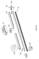
- Fig. 12 is an exploded perspective view of a windshield wiper blade structure according to a fourth embodiment of the present invention.
- the windshield wiper blade structure includes a support strip 51, a wiper strip 52, two wind deflector strips 53, two elastic locking elements 26 and two end caps 27, a bracket 56, and a protective cover 57. Since the end caps 27 (referring to Figs. 5 and 8 ), the elastic locking elements 26 (referring to Figs. 3 and 7 ), the wiper strip 52, the wind deflector strips 53, the bracket 56, and the protective cover 57 in the fourth embodiment of the present invention are structurally and functionally similar to those in the first embodiment, they are not discussed in details herein.
- the fourth embodiment is different from the first embodiment in the support strip 51 that includes an expanded through hole 511 and a longitudinally extended long slit 512.
- the expanded through hole 511 is formed near one of two longitudinally opposite ends of the support strip 51.
- the long slit 512 extends at two ends toward the two longitudinally opposite ends of the support strip 51 without extending therethrough. However, one of the two ends of the long slit 512 communicates with the expanded through hole 511.
- the wiper strip 52 is correspondingly formed at two opposite lateral sides with a pair of longitudinally extended grooves 521 and has a wiping lip 522.
- the wiping lip 522 is made of a flexible material, such as a rubber material.
- an end of the wiper strip 52 can be pulled through the expanded through hole 511, so that the wiper strip 52 can be then downward pressed through the long slit 512 to engage the pair of grooves 521 with the portions of the support strip 51 at two opposite sides of the long slit 512, bringing the wiper strip 52 to be fixedly connected to the support strip 51.
- connection of the end cap 27 to one end of the support strip 51 can also be understood by referring to Figs. 5 , 6 and 7 .
- To connect the end cap 27 to the support strip 51 first compress the two elastic arms 261 of the locking element 26 for them to move toward each other and become aligned with the two spaces 274. Thereafter, fit the end cap 27 on an outer end of the corresponding guide rail 532 of wind deflector strip 53 and then guide the two elastic arms 261 through the two spaces 274 to the two notches 275, allowing two lateral outer sides of the support strip 51 to locate in the end cap 27.
- one end of the already assembled support strip 51 and wind deflector strip 53 can be smoothly set in the shell 272 of the end cap 27.
- the compressed elastic arms 261 are released, allowing the elastic arms 261 to elastically spring outward to thereby move into and firmly press against the two notches 275.
- the end cap 27 is fixedly held to the support strip 51, as shown in Fig. 8 .
- the windshield wiper blade structure includes a support strip 61, a wiper strip 62, two wind deflector strips 63, two elastic locking elements 26 and two end caps 27, a bracket 66, and a protective cover 67. Since the end caps 27 (referring to Figs. 5 and 8 ), the elastic locking elements 26 (referring to Figs. 3 and 7 ), the support strip 61, the wiper strip 62, the bracket 66, and the protective cover 67 in the fifth embodiment of the present invention are structurally and functionally similar to those in the first embodiment, they are not discussed in details herein.
- the fifth embodiment is different from the first embodiment in the wind deflector strips 63, each of which includes a wind deflecting section 631, an insertion channel 632, and two guide rails 633.
- the insertion channel 632 is located between the wind deflecting section 631 and the guide rails 633 for the support strip 61 to insert thereinto.
- the wiper strip 62 is correspondingly formed at two opposite lateral sides with a pair of longitudinally extended grooves 621.
- connection of the end cap 27 to one end of the support strip 61 can also be understood by referring to Figs. 5 , 6 and 7 .
- To connect the end cap 27 to the support strip 61 first compress the two elastic arms 261 of the locking element 26 for them to move toward each other and become aligned with the two spaces 274. Thereafter, fit the end cap 27 on an outer end of the corresponding guide rail 633 of wind deflector strip 63 and then guide the two elastic arms 261 through the two spaces 274 to the two notches 275, allowing two lateral outer sides of the support strip 61 to locate in the end cap 27.
- one end of the already assembled support strip 61 and wind deflector strip 63 can be smoothly set in the shell 272 of the end cap 27.
- the compressed elastic arms 261 are released, allowing the elastic arms 261 to elastically spring outward to thereby move into and firmly press against the two notches 275.
- the end cap 27 is fixedly held to the support strip 61, as shown in Fig. 8 .
- the windshield wiper blade structure of the present invention advantageously allows a user to remove the aged wiper strip from the support strip(s) simply by compressing the elastic arms of each of the elastic locking elements toward each other to release the elastic locking elements from the two end caps. That is, in the windshield wiper blade structure of the present invention, the end caps can be easily removed from two ends of the support strip(s) and the wiper strip can be conveniently replaced to reduce the user's maintenance and repair costs.
- Another advantage provided by the present invention is the end caps and the elastic locking elements can be used with differently designed support strip(s) and wind deflector strips, allowing the present invention to be applied to different types of windshield wiper blade products.
Landscapes
- Engineering & Computer Science (AREA)
- Mechanical Engineering (AREA)
- Body Structure For Vehicles (AREA)
Abstract
Description
- The present invention relates to a windshield wiper blade structure, and more particularly to a windshield wiper blade structure that allows a user to easily replace a wiper strip thereof with a new one.
- A windshield wiper structure is usually installed close to a windshield of a motor vehicle, and a wiper blade thereof is driven to swing back and forth within a generally sector-shaped wiping area. The wiper blade has a wiper strip made of a rubber material for wiping off deposited dust or water, such as wiping accumulated rainwater or snow from the windshield.
-
Fig. 1 is an exploded perspective view of a conventional windshield wiper blade structure; and -
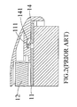
Fig. 2 is a fragmentary, enlarged and assembled sectional view of the conventional windshield wiper blade structure ofFig. 1 . As shown, the conventional windshield wiper blade structure includes asupport strip 11, twowind deflector strips 12 disposed on a top of thesupport strip 11, awiper strip 13 disposed on a bottom of thesupport strip 11, twoend caps 14 fitted to two longitudinally opposite ends of the associatedsupport strip 11 andwiper strip 13, abracket 15, and aprotective cover 16 covering thebracket 15. Thesupport strip 11 is provided near each of the two opposite ends thereof with anelastic hooking portion 111, which is formed by punching with a free end upward projecting from the top of thesupport strip 11 at an inclination to provide a degree of elasticity. Each of theend cap 14 is internally provided at a predetermined position with anotch 141 corresponding to theelastic hooking portion 111, such that when theend cap 14 is fitted onto one end of thesupport strip 11, thenotch 141 is engaged with theelastic hooking portion 111 to thereby hold theend cap 14 to the end ofsupport strip 11 and thewiper strip 13 to the bottom of thesupport strip 11. With these arrangements, thewiper strip 13 is prevented from sliding off thesupport strip 11. The windshield wiper blade structure can be detachably connected to a wiper bracket provided on the motor vehicle, and driven to swing back and forth on the windshield to wipe off rainwater. - After having been swung back and forth on the windshield to wipe off rainwater or snow over a long period of time, the
wiper strip 13 tends to become deformed or damaged due to elastic fatigue and must be replaced with a new one. In the above described conventional windshield wiper blade structure, theend caps 14 are not detachable from thesupport strip 11 once they are engaged with theelastic hooking portions 111. Thewiper strip 13 can be removed from thesupport strip 11 only when theend caps 14 and the elastic hookingportions 111 are destroyed to separate theend caps 14 from the ends of thesupport strip 11. That is, when thewiper strip 13 is aged or damaged, the whole set of the conventional windshield wiper blade structure must be replaced. This is of course not economical to do so. - In addition, since the
support strip 11 is made of a relatively tough material and has a relatively large thickness, it is uneasy to punch thesupport strip 11 at two ends thereof to form the twoelastic hooking portions 111. Thus, the conventional windshield wiper blade structure is manufactured at increased cost. - It is therefore a primary object of the present invention to provide a windshield wiper blade structure that allows a user to easily replace a wiper strip thereof with a new one, so as to overcome the problem of requiring high cost to replace a whole set of windshield wiper blade when a wiper strip thereof is aged or damaged, as found in the prior art.
- To achieve the above and other objects, the windshield wiper blade structure according to an embodiment of the present invention includes a support strip; a wiper strip being disposed on a first face of the support strip; a set of wind deflector strips being disposed on a second face of the support strip opposite to the wiper strip; and a binding component.
- The binding component can be compressed to deform, so as to be fitted to two longitudinally opposite ends of the support strip, and the binding component can be then released to restore to its original state and become locked to the two longitudinally opposite ends of the support strip.
- The windshield wiper blade structure according to another embodiment of the present invention includes a support strip being formed with a plurality of holes; a wiper strip being disposed on a first face of the support strip; a set of flexible strips being set on two opposite lateral sides of the wiper strip; a set of clamping elements being extended through the plurality of holes on the support strip to thereby clamp the support strip, the flexible strips and the wiper strip together to form an integral body; a set of wind deflector strips being disposed on a second face of the support strip opposite to the wiper strip; and a binding component. The binding component can be compressed to deform, so as to be fitted to two longitudinally opposite ends of the support strip, and the binding component can be then released to restore to its original state and become locked to the two longitudinally opposite ends of the support strip.
- The binding component includes a pair of elastic locking elements and a pair of end caps. Each of the elastic locking elements includes a pair of elastic arms being fixed to two opposite lateral sides of the support strip near one of the two longitudinally opposite ends of the support strip, and each of the end caps is configured for detachably connecting to one of the two longitudinally opposite ends of the support strip. By compressing the two elastic arms toward each other to thereby move the elastic arms into the corresponding end cap and then releasing the elastic arms to allow them to expand outward, the elastic arms can engage with the end cap to lock the same in place.
- The windshield wiper blade structure according to a further embodiment of the present invention includes a set of support strips, a wiper strip, a set of wind deflector strips, a set of elastic locking elements, and a set of end caps. The wiper strip is provided at two opposite lateral sides with a plurality of grooves each, and the set of support strips is set in two oppositely corresponding grooves. The set of wind deflector strips is disposed on one face of the support strips. Each of the elastic locking elements includes two elastic arms, and is fixed to one of two longitudinally opposite ends of the set of support strips. Each of the end caps is internally provided with two notches corresponding to the two elastic arms of the elastic locking element, and is detachably fitted to one of the two longitudinally opposite ends of the set of support strips. By compressing the two elastic arms toward each other to allow fitting of the end cap on one end of the set of support strips and then releasing the elastic arms to allow them to expand outward, the elastic arms can be engaged with the notches on the end cap.
- The windshield wiper blade structure according to a still further embodiment of the present invention includes a support strip, a wiper strip, a set of wind deflector strips, a set of elastic locking elements, and a set of end caps. The wiper strip is disposed on one face of the support strip, and the set of wind deflector strips is disposed on another face of the support strip opposite to the wiper strip. Each of the elastic locking elements includes two elastic arms, and is fixed to one of two longitudinally opposite ends of the support strip. Each of the end caps is internally provided with two notches corresponding to the two elastic arms of one elastic locking element. By compressing the two elastic arms toward each other to allow fitting of the end cap on one end of the support strip and then releasing the elastic arms to allow them to expand outward, the elastic arms can be engaged with the notches on the end cap. The support strip is provided with a long slit, an end of which extends through one end of the support strip to form an open end, and the other end of the long slit extends toward the other end of the support strip without extending therethrough, so that a stopper portion is formed at the other end of the support strip.
- With the above arrangements, the end caps can be connected to or removed from two longitudinally opposite ends of the support strip simply by compressing the two elastic arms on each of the elastic locking elements toward each other and then releasing the two elastic arms, enabling a user to easily remove the damaged or aged wiper strip from the support strip for replacement without the need of discarding a whole set of the windshield wiper blade structure. Therefore, the maintenance and repair cost can be reduced.
- The structure and the technical means adopted by the present invention to achieve the above and other objects can be best understood by referring to the following detailed description of the preferred embodiments and the accompanying drawings, wherein
-
Fig. 1 is an exploded perspective view of a conventional windshield wiper blade structure; -
Fig. 2 is a fragmentary, enlarged and assembled sectional view of the conventional windshield wiper blade structure ofFig. 1 ; -
Fig. 3 is an exploded perspective view of a windshield wiper blade structure according to a first embodiment of the present invention; -
Fig. 4 is an assembled cross-sectional view of the windshield wiper blade structure ofFig. 3 ; -
Fig. 5 is a perspective view showing an inner structure of a first embodiment of an end cap for the windshield wiper blade structure ofFig. 3 ; -
Fig. 6 shows a first manner of connecting the end cap to an end of a support strip for the windshield wiper blade structure ofFig. 3 ; -
Fig. 7 shows a second manner of connecting the end cap to an end of the support strip for the windshield wiper blade structure ofFig. 3 ; -
Fig. 8 shows how the end cap is locked to the support strip via an elastic locking element; -
Fig. 9 is a perspective view showing an inner structure of a second embodiment of the end cap for the windshield wiper blade structure ofFig. 3 ; -
Fig. 10 is an exploded perspective view of a windshield wiper blade structure according to a second embodiment of the present invention; -
Fig. 11 is an exploded perspective view of a windshield wiper blade structure according to a third embodiment of the present invention; -
Fig. 12 is an exploded perspective view of a windshield wiper blade structure according to a fourth embodiment of the present invention; and -
Fig. 13 is an exploded perspective view of a windshield wiper blade structure according to a fifth embodiment of the present invention. - The present invention will now be described with some preferred embodiments thereof with reference to the accompanying drawings.
- Please refer to
Fig. 3 that is an exploded perspective view of a windshield wiper blade structure according to a first embodiment of the present invention, and toFig. 4 that is an enlarged assembled cross-sectional view of the windshield wiper blade structure ofFig. 3 . As shown, the windshield wiper blade structure in the first embodiment includes asupport strip 21, awiper strip 22, twoflexible strips 23, a plurality ofclamping elements 24, twowind deflector strips 25, abinding component 260, abracket 28, and aprotective cover 29. Thebinding component 260 includes twoelastic locking elements 26 and twoend caps 27. - The
support strip 21 is formed with a plurality of pairs ofholes 211 and twonotched sections 212. The pairs ofholes 211 are axially equally spaced along thesupport strip 21 and the holes in each of the pairs are arranged side by side on thesupport strip 21. Thewiper strip 22 is located below thesupport strip 21, and includes an elongatetop plate 221 for bearing against thesupport strip 21, a plurality of longitudinally extendedgrooves 222 correspondingly formed on each of two opposite lateral sides thereof, and awiping lip 223 located opposite to thetop plate 221. The twoflexible strips 23 are separately set in twooppositely corresponding grooves 222 on thewiper strip 22. Each of the clampingelements 24 has two downward extended lateral sides to provide two L-shaped clampingarms 241. By extending the L-shaped clampingarms 241 of each of the clampingelements 24 through one of the pairs ofholes 211 on thesupport strip 21 to engage free edges of the L-shaped clampingarms 241 with another two oppositely correspondinggrooves 222 on thewiper strip 22 below the twoflexible strips 23, thesupport strip 21, theflexible strips 23, and thewiper strip 22 can be clamped together to form an integral body. - The two wind deflector strips 25 each have a
wind deflecting section 251. Two opposite parallel edges of thewind deflecting section 251 are downward and then inward bent toward each other to form twoguide rails 252, such that aslide way 253 is defined between thewind deflecting section 251 and the twoguide rails 252. Thesupport strip 21 can be slid along theguide rails 252 into theslide way 253, so that thewind deflector strip 25 is held to a top of thesupport strip 21. - The
elastic locking elements 26 each have two downward extendedelastic arms 261 separately formed at two opposite lateral sides thereof, and are separately fitted in the two notchedsections 212 on thesupport strip 21. - The two
end caps 27 are separately connected to two longitudinally opposite ends of thesupport strip 21.Fig. 5 is a perspective view showing an inner structure of a first embodiment of the end caps 27. As shown, each of the end caps 27 has amain body 271 and ashell 272 covering themain body 271. Two opposite lateral sides of theshell 272 are downward and inward bent toward each other, and twonotches 275 are separately formed at free edges of the inward bent lateral sides of theshell 272 corresponding to theelastic arms 261 of theelastic locking element 26. Aspace 274 is formed between each of two lateral sides of themain body 271 and theshell 272. Each of the twospaces 274 is slightly larger than a thickness of theelastic arm 261, so that theelastic arms 261 of theelastic locking element 26 can pass through thespaces 274. The twoelastic arms 261 on theelastic locking element 26 can be compressed toward each other or be released to elastically expand outward. - The
bracket 28 is disposed on the top of thesupport strip 21 to locate between the two wind deflector strips 25 for a wiper arm (not shown) to pivotally connect thereto, so that the wiper arm can drive thebracket 28 to move reciprocatingly. Theprotective cover 29 is fitted on thebracket 28 to protect thebracket 28 against rust due to invasion of and corrosion by water. -
Fig. 6 shows a first manner of connecting theend cap 27 to one end of thesupport strip 21 according to the present invention. Please refer toFigs. 5 and6 at the same time. To connect theend cap 27 to one end of thesupport strip 21, first compress the twoelastic arms 261 of the lockingelement 26 at that end for them to move toward each other and become aligned with the twospaces 274. Thereafter, fit theend cap 27 on the twoguide rails 252 at an outer end of the correspondingwind deflector strip 25 and then guide the twoelastic arms 261 through the twospaces 274 to the twonotches 275, allowing the two lateral sides of thesupport strip 21 to locate in theend cap 27. At this point, one end of the already assembledsupport strip 21 andwind deflector strip 25 can be smoothly set in theshell 272 of theend cap 27. Then, the compressedelastic arms 261 are released, allowing theelastic arms 261 to elastically spring outward to thereby move into and firmly press against the twonotches 275. With the twoelastic arms 261 being separately engaged with the twonotches 275, theend cap 27 is fixedly held to thesupport strip 21, as shown inFig. 8 . - When it is desired to replace the
wiper strip 22, simply compress the twoelastic arms 261 of theelastic locking element 26 at each of two ends of thesupport strip 21, so that the twoelastic arms 261 are moved toward each other to align with the twospaces 274. At this point, theend cap 27 is no longer held to thesupport strip 21 by theelastic arms 261, and theelastic arms 261 can be slid along the twospaces 274 to move thesupport strip 21 out of theend cap 27. With thesupport strip 21 disengaged from the end caps 27, thewiper strip 22 can be removed from thesupport strip 21 and replaced with a new one. -
Fig. 7 shows a second manner of connecting theend cap 27 to one end of thesupport strip 21 according to the present invention. Please refer toFigs. 5 and7 at the same time. To enable easy connection of theend cap 27 to one end of thesupport strip 21, free edges of theelastic arms 261 can be further outward extended to form apush portion 262 each, so that thepush portions 262 are projected from thenotches 275 when theelastic arms 261 are engaged with thenotches 275. With thepush portions 262, a user can connect or disconnect theend cap 27 to or from thesupport strip 21 using two hands without the need of any tool. -
Fig. 8 is a perspective view showing an inner structure of a second embodiment of theend cap 27. As shown, in the second embodiment thereof, theend cap 27 includes amain body 271 and ashell 272 covering themain body 271. Theshell 272 of theend cap 27 in the second embodiment thereof is provided at free edges of two inward bent opposite lateral sides with anotch 275 each, an axially rear end of which is an open end; and at two axially rear inner corners with a clampingportion 276 each for clamping thesupport strip 21 in place in theend cap 27, as shown inFig. 9 . Themain body 271 of theend cap 27 in the second embodiment thereof is formed near one end with arecess 277. With these arrangements, theend cap 27 can be more easily connected to or removed from thesupport strip 21. - Please refer to
Fig. 10 that is an exploded perspective view of a windshield wiper blade structure according to a second embodiment of the present invention. In the second embodiment, the windshield wiper blade structure includes a plurality of support strips 31, awiper strip 32, two wind deflector strips 33, twoelastic locking elements 26 and twoend caps 27, abracket 36, and aprotective cover 37. Thewiper strip 32 is correspondingly formed at two opposite lateral sides with a plurality of longitudinally extendedgrooves 321 corresponding to the support strips 31. The support strips 31 are used to hold thewiper strip 32 and the wind deflector strips 33 thereto. Thewiper strip 32 is used to wipe rainwater or snow off a windshield. The wind deflector strips 33 are used to guide rainwater to flow. Thebracket 36 is used for a wiper arm (not shown) to pivotally connected thereto, so that the wiper arm can drive thesupport strip 31 to swing within a wiping area. Theprotective cover 37 protectively covers thebracket 36. Please refer toFigs. 5 and8 for the end caps 27 and toFigs. 3 and7 for theelastic locking elements 26 in the second embodiment of the present invention. Since the end caps 27 and theelastic locking elements 26 in the second embodiment of the present invention are structurally and functionally similar to those in the first embodiment, they are not discussed in details herein. - The second embodiment is different from the first embodiment in having two support strips 31. To assemble the supporting
strips 31, the wind deflector strips 33 and thewiper strip 32 to one another, first correspondingly engage the two support strips 31 with twocorresponding grooves 321 on the two opposite lateral sides of thewiper strip 32, and then slide the two support strips 31 into the wind deflector strips 33. Finally, connect the end caps 27 to two longitudinally opposite ends of the already assembled wind deflector strips 33 andwiper strip 32, so that theelastic locking elements 26 are engaged with and locked to the end caps 27 to thereby hold the end caps 27 to the support strips 31. The clampingelements 24 in the first embodiment for clamping thesupport strip 21 to thewiper strip 22 can therefore be omitted. - The connection of the
end cap 27 to one end of the support strips 31 can also be understood by referring toFigs. 5 ,6 and7 . To connect theend cap 27 to the support strips 31, first compress the twoelastic arms 261 of the lockingelement 26 for them to move toward each other and become aligned with the twospaces 274. Thereafter, fit theend cap 27 on an outer end of thecorresponding guide rail 332 of thewind deflector strip 33 and then guide the twoelastic arms 261 through the twospaces 274 to the twonotches 275, allowing two lateral outer sides of the two support strips 31 to locate in theend cap 27. At this point, one end of the already assembled support strips 31 andwind deflector strip 33 can be smoothly set in theshell 272 of theend cap 27. Then, the compressedelastic arms 261 are released, allowing theelastic arms 261 to elastically spring outward to thereby move into and firmly press against the twonotches 275. With the twoelastic arms 261 being separately engaged with the twonotches 275, theend cap 27 is fixedly held to the support strips 31, as shown inFig. 8 . - Please refer to
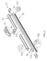
Fig. 11 that is an exploded perspective view of a windshield wiper blade structure according to a third embodiment of the present invention. In the third embodiment, the windshield wiper blade structure includes asupport strip 41, awiper strip 42, two wind deflector strips 43, twoelastic locking elements 26 and twoend caps 27, abracket 46, and aprotective cover 47. Thewiper strip 42 is correspondingly formed at two opposite lateral sides with a pair of longitudinally extendedgrooves 421. Since the end caps 27 (referring toFigs. 5 and8 ), the elastic locking elements 26 (referring toFigs. 3 and7 ), thewiper strip 42, the wind deflector strips 43, thebracket 46, and theprotective cover 47 in the third embodiment of the present invention are structurally and functionally similar to those in the first embodiment, they are not discussed in details herein. - The third embodiment is different from the first embodiment in the
support strip 41 that includes a longitudinally extendedlong slit 411. Thelong slit 411 is aligned with a centerline of thesupport strip 41 to extend toward two longitudinally opposite ends of thesupport strip 41. One of two opposite ends of thelong slit 411 extends through one of two ends of thesupport strip 41 to forms anopen end 412. The other end of thelong slit 411 ends near the other end of thesupport strip 41 without extending therethrough, so that astopper portion 413 is formed at the other end of thesupport strip 41. With these arrangements, thesupport strip 41 forms two parallelly extended long strip parts, which are located at two opposite sides of thelong slit 411 and connected to each other only at thestopper portion 413. To assemble thewiper strip 42 and thesupport strip 41 to each other, simply slide thewiper strip 42 into thelong slit 411 via theopen end 412 with the pair ofgrooves 421 separately engaging with the two long strip parts of thesupport strip 41, so that thewiper strip 42 and thesupport strip 41 are connected together. - The connection of the
end cap 27 to one end of thesupport strip 41 can also be understood by referring toFigs. 5 ,6 and7 . To connect theend cap 27 to thesupport strip 41, first compress the twoelastic arms 261 of the lockingelement 26 for them to move toward each other and become aligned with the twospaces 274. Thereafter, fit theend cap 27 on an outer end of thecorresponding guide rail 432 of thewind deflector strip 43 and then guide the twoelastic arms 261 through the twospaces 274 to the twonotches 275, allowing two lateral outer sides of thesupport strip 41 to locate in theend cap 27. At this point, one end of the already assembledsupport strip 41 andwind deflector strip 43 can be smoothly set in theshell 272 of theend cap 27. Then, the compressedelastic arms 261 are released, allowing theelastic arms 261 to elastically spring outward to thereby move into and firmly press against the twonotches 275. With the twoelastic arms 261 being separately engaged with the twonotches 275, theend cap 27 is fixedly held to thesupport strip 41, as shown inFig. 8 . - Please refer to
Fig. 12 that is an exploded perspective view of a windshield wiper blade structure according to a fourth embodiment of the present invention. In the fourth embodiment, the windshield wiper blade structure includes asupport strip 51, awiper strip 52, two wind deflector strips 53, twoelastic locking elements 26 and twoend caps 27, abracket 56, and aprotective cover 57. Since the end caps 27 (referring toFigs. 5 and8 ), the elastic locking elements 26 (referring toFigs. 3 and7 ), thewiper strip 52, the wind deflector strips 53, thebracket 56, and theprotective cover 57 in the fourth embodiment of the present invention are structurally and functionally similar to those in the first embodiment, they are not discussed in details herein. - The fourth embodiment is different from the first embodiment in the
support strip 51 that includes an expanded throughhole 511 and a longitudinally extendedlong slit 512. The expanded throughhole 511 is formed near one of two longitudinally opposite ends of thesupport strip 51. Thelong slit 512 extends at two ends toward the two longitudinally opposite ends of thesupport strip 51 without extending therethrough. However, one of the two ends of thelong slit 512 communicates with the expanded throughhole 511. Thewiper strip 52 is correspondingly formed at two opposite lateral sides with a pair of longitudinally extendedgrooves 521 and has a wipinglip 522. The wipinglip 522 is made of a flexible material, such as a rubber material. With the expanded throughhole 511 formed at one end of thesupport strip 51, an end of thewiper strip 52 can be pulled through the expanded throughhole 511, so that thewiper strip 52 can be then downward pressed through thelong slit 512 to engage the pair ofgrooves 521 with the portions of thesupport strip 51 at two opposite sides of thelong slit 512, bringing thewiper strip 52 to be fixedly connected to thesupport strip 51. - The connection of the
end cap 27 to one end of thesupport strip 51 can also be understood by referring toFigs. 5 ,6 and7 . To connect theend cap 27 to thesupport strip 51, first compress the twoelastic arms 261 of the lockingelement 26 for them to move toward each other and become aligned with the twospaces 274. Thereafter, fit theend cap 27 on an outer end of thecorresponding guide rail 532 ofwind deflector strip 53 and then guide the twoelastic arms 261 through the twospaces 274 to the twonotches 275, allowing two lateral outer sides of thesupport strip 51 to locate in theend cap 27. At this point, one end of the already assembledsupport strip 51 andwind deflector strip 53 can be smoothly set in theshell 272 of theend cap 27. Then, the compressedelastic arms 261 are released, allowing theelastic arms 261 to elastically spring outward to thereby move into and firmly press against the twonotches 275. With the twoelastic arms 261 being separately engaged with the twonotches 275, theend cap 27 is fixedly held to thesupport strip 51, as shown inFig. 8 . - Please refer to
Fig. 13 that is an exploded perspective view of a windshield wiper blade structure according to a fifth embodiment of the present invention. In the fifth embodiment, the windshield wiper blade structure includes asupport strip 61, awiper strip 62, two wind deflector strips 63, twoelastic locking elements 26 and twoend caps 27, abracket 66, and aprotective cover 67. Since the end caps 27 (referring toFigs. 5 and8 ), the elastic locking elements 26 (referring toFigs. 3 and7 ), thesupport strip 61, thewiper strip 62, thebracket 66, and theprotective cover 67 in the fifth embodiment of the present invention are structurally and functionally similar to those in the first embodiment, they are not discussed in details herein. - The fifth embodiment is different from the first embodiment in the wind deflector strips 63, each of which includes a
wind deflecting section 631, aninsertion channel 632, and twoguide rails 633. Theinsertion channel 632 is located between thewind deflecting section 631 and theguide rails 633 for thesupport strip 61 to insert thereinto. Thewiper strip 62 is correspondingly formed at two opposite lateral sides with a pair of longitudinally extendedgrooves 621. To assemble thesupport strip 61, the wind deflector strips 63 and thewiper strip 62 to one another, first insert thesupport strip 61 into theinsertion channels 632 on the two wind deflector strips 63, so that the wind deflector strips 63 are fixedly connected to thesupport strip 61. Then, slide an end of thewiper strip 62 into between the twoguide rails 633, so that theguide rails 633 are engaged with the pair ofgrooves 621, bringing thewiper strip 62 to connect to the wind deflector strips 63 and locate below thesupport strip 61. In this manner, thesupport strip 61, the wind deflector strips 63 and thewiper strip 62 are assembled together and held in place relative one another. - The connection of the
end cap 27 to one end of thesupport strip 61 can also be understood by referring toFigs. 5 ,6 and7 . To connect theend cap 27 to thesupport strip 61, first compress the twoelastic arms 261 of the lockingelement 26 for them to move toward each other and become aligned with the twospaces 274. Thereafter, fit theend cap 27 on an outer end of thecorresponding guide rail 633 ofwind deflector strip 63 and then guide the twoelastic arms 261 through the twospaces 274 to the twonotches 275, allowing two lateral outer sides of thesupport strip 61 to locate in theend cap 27. At this point, one end of the already assembledsupport strip 61 andwind deflector strip 63 can be smoothly set in theshell 272 of theend cap 27. Then, the compressedelastic arms 261 are released, allowing theelastic arms 261 to elastically spring outward to thereby move into and firmly press against the twonotches 275. With the twoelastic arms 261 being separately engaged with the twonotches 275, theend cap 27 is fixedly held to thesupport strip 61, as shown inFig. 8 . - When the wiper strip is subjected to elastic fatigue and becomes aged, the windshield wiper blade structure of the present invention advantageously allows a user to remove the aged wiper strip from the support strip(s) simply by compressing the elastic arms of each of the elastic locking elements toward each other to release the elastic locking elements from the two end caps. That is, in the windshield wiper blade structure of the present invention, the end caps can be easily removed from two ends of the support strip(s) and the wiper strip can be conveniently replaced to reduce the user's maintenance and repair costs.
- Another advantage provided by the present invention is the end caps and the elastic locking elements can be used with differently designed support strip(s) and wind deflector strips, allowing the present invention to be applied to different types of windshield wiper blade products.
- The present invention has been described with some preferred embodiments thereof and it is understood that many changes and modifications in the described embodiments can be carried out without departing from the scope and the spirit of the invention that is intended to be limited only by the appended claims.
Claims (15)
- A windshield wiper blade structure, comprising:a support strip(21);a wiper strip(22) being disposed on a first face of the support strip(21);a set of wind deflector strips(25) being disposed on a second face of the support strip(21) opposite to the wiper strip(22); anda binding component(260);wherein the binding component(260) is pressed to fitted into two longitudinally opposite end of the support strip(21), and then the binding component(260) is released to its original state so as to lock the binding component(260) into the two longitudinally opposite ends of the support strip(21).
- The windshield wiper blade structure as claimed in claim 1, wherein the binding component(260) includes a pair of elastic locking elements(26) and a pair of end caps(27); each of the elastic locking elements(26) including two elastic arms(261) being fixed to two opposite lateral sides of the support strip(21) near one of the two longitudinally opposite ends of the support strip(21), and each of the end caps being configured for detachably connecting to one of the two longitudinally opposite ends of the support strip(21); whereby by compressing the two elastic arms(261) toward each other to thereby move the elastic arms(261) into the corresponding end cap(27) and then releasing the elastic arms(261) to allow them to expand outward, the elastic arms(261) can engage with the end cap(27) to lock the same in place.
- The windshield wiper blade structure as claimed in claim 2, wherein each of the end caps(27) is provided at predetermined positions with two notches(275), and the released elastic arms of each of the elastic locking elements(26) are extending into the notches(275) to engage therewith.
- The windshield wiper blade structure as claimed in claim 3, wherein each of the end caps(27) includes a main body(271) and a shell(272) covering the main body(271); and the notches(275) are formed on an inner side of the shell(272).
- The windshield wiper blade structure as claimed in claim 4, wherein a space(274) is formed between each of two opposite lateral sides of the main body(271) and the inner side of the shell(272), and the space(274) is larger than a thickness of each of the elastic arms(261).
- The windshield wiper blade structure as claimed in claim 5, wherein the elastic arms(261) each have a free edge being further extended to provide a push portion(262), such that the push portions(262) are projected from the notches(275) when the elastic arms(261) are extended into and engaged with the notches(275).
- A windshield wiper blade structure, comprising:a plurality of support strips(21);a wiper strip(22), having a plurality of grooves(222) formed on each side of said wiper strip(21), and the support strips(21) disposed on corresponding grooves(222);a set of wind deflector strips(25) being disposed on a side of the support strips(21);a set of elastic locking element(26) being disposed on a end of the support strips(21),; anda set of end cap(27) being inserted on the support strips(21);whereby by compressing the two elastic locking elements(26) to deform them and then releasing them, the elastic locking elements(26) can restore to an original state thereof andbecome engaged with the end caps(27) to lock the end caps(27) thereto.
- The windshield wiper blade structure as claimed in claim 7, wherein the set of elastic locking element(26) has two elastic locking elements(26), the set of end cap(27) has two end caps(27), the elastic lock element(26) has at lest one elastic arms(261), the end cap(27) has at least one notches(275), each elastic arm(261) is engaged into the notch(275) .
- The windshield wiper blade structure as claimed in claim 8, wherein each of the end caps(27)includes a main body(271) and a shell(272) covering the main body(271); and the notches(275) are formed on an inner side of the shell(272).
- The windshield wiper blade structure as claimed in claim 9, wherein a space(274) is formed between each of two opposite lateral sides of the main body(271) and the inner side of the shell(272), and the space is larger than a thickness of each of the elastic arms(261).
- A windshield wiper blade structure, comprising:a support strip(41);a wiper strip(42) being disposed on a first face of the support strip(41);a set of wind deflector strips(43) being disposed on a second face of the support strip(41) opposite to the wiper strip(42);a set of elastic locking elements(26) fixed on the end of the support strip(41), and at least one elastic arm(261) extending downwardly from each side of the elastic locking elements(26) ; anda set of end caps(27) disposed on the support strip(41) having a notch(275) corresponding to the elastic arms(261) ;whereby by compressing the two elastic arms(261) toward each other to thereby move the elastic arms(261) into the corresponding set of end cap(27), and then releasing the elastic arms(261) to allow them to expand outward, the elastic arms(261) can engage with the corresponding notch(275).
- The windshield wiper blade structure as claimed in claim 11, wherein the support strip is provided with a longitudinally extended long slit(411), one of two opposite ends of the long slit(411) extending through one end of the two ends of the support strip(41) to forms an open end, and the other end of the long slit(411) ending near the other end of the support strip(41) without extending therethrough, so that a stopper portion(413) is formed at the other end of the support strip(41).
- The windshield wiper blade structure as claimed in claim 11, wherein the support strip(41) has an expanded through hole(511) and a longitudinally extended long slit(512) provided thereon; the long slit(512) having two ends extending toward the two longitudinally opposite ends of the support strip(41) without extending therethrough, while one of the two ends of the long slit(512) being communicating with the expanded through hole(511); and wherein an upper part of the wiper strip(52) is longitudinally set in the long slit(512).
- A windshield wiper blade structure, comprising:a support strip(21) being formed with a plurality of holes;a wiper strip(22) being disposed on a first face of the support strip(21);a set of flexible strips(23) being set on two opposite lateral sides of the wiper strip(22);a set of clamping elements(24) being extended through the plurality of holes on the support strip(21) to thereby clamp the support strip(21), the flexible strips(23) and the wiper strip(22) together to form an integral body;a set of two wind deflector strips(25) being disposed on a second face of the support strip(21) opposite to the wiper strip(22); anda binding component(260);wherein the binding component(260) can be compressed to deform, so as to be fitted to two longitudinally opposite ends of the support strip(21), and the binding component(260) can be then released to restore to its original state and become locked to the two longitudinally opposite ends of the support strip(21).
- The windshield wiper blade structure as claimed in claim 14, wherein the binding component(260) includes a pair of elastic locking elements(26) and a pair of end caps(27); each of the elastic locking elements(26) including a pair of elastic arms(26) being fixed to two opposite lateral sides of the support strip(21) near one of the two longitudinally opposite ends thereof, and each of the end caps(27) being configured for detachably connecting to one of the two longitudinally opposite ends of the support strip(21); whereby by compressing the two elastic arms(261) toward each other to thereby move the elastic arms(261) into the corresponding end cap(27) and then releasing the elastic arms(261) to allow them to expand outward, the elastic arms(261) can engage with the end cap(27) to lock the same in place.
Priority Applications (2)
| Application Number | Priority Date | Filing Date | Title |
|---|---|---|---|
| EP09156212.4A EP2233375B1 (en) | 2009-03-25 | 2009-03-25 | Windshield wiper blade structure |
| PL09156212T PL2233375T3 (en) | 2009-03-25 | 2009-03-25 | Windshield wiper blade structure |
Applications Claiming Priority (1)
| Application Number | Priority Date | Filing Date | Title |
|---|---|---|---|
| EP09156212.4A EP2233375B1 (en) | 2009-03-25 | 2009-03-25 | Windshield wiper blade structure |
Publications (2)
| Publication Number | Publication Date |
|---|---|
| EP2233375A1 true EP2233375A1 (en) | 2010-09-29 |
| EP2233375B1 EP2233375B1 (en) | 2014-02-26 |
Family
ID=40897342
Family Applications (1)
| Application Number | Title | Priority Date | Filing Date |
|---|---|---|---|
| EP09156212.4A Not-in-force EP2233375B1 (en) | 2009-03-25 | 2009-03-25 | Windshield wiper blade structure |
Country Status (2)
| Country | Link |
|---|---|
| EP (1) | EP2233375B1 (en) |
| PL (1) | PL2233375T3 (en) |
Cited By (7)
| Publication number | Priority date | Publication date | Assignee | Title |
|---|---|---|---|---|
| CN102963337A (en) * | 2011-07-25 | 2013-03-13 | 东莞山多力汽车配件有限公司 | Windshield wiper structure with composite framework |
| USD685712S1 (en) | 2011-03-23 | 2013-07-09 | Kcw Corporation | Wiper |
| WO2013151222A1 (en) * | 2012-04-06 | 2013-10-10 | Yu Byeng-Gab | Vehicle wiper end cap |
| US20160016550A1 (en) * | 2014-07-17 | 2016-01-21 | Robert Bosch Gmbh | End cap device for a wiper blade |
| FR3063054A1 (en) * | 2017-02-22 | 2018-08-24 | Valeo Systemes D'essuyage | ADAPTABLE END CAP FOR TUMBLING BRUSH |
| CN110691720A (en) * | 2017-04-28 | 2020-01-14 | 法雷奥系统公司 | End piece for a wiper blade |
| US11440508B1 (en) * | 2021-03-08 | 2022-09-13 | Danyang Upc Auto Parts Co., Ltd. | Wiper |
Citations (6)
| Publication number | Priority date | Publication date | Assignee | Title |
|---|---|---|---|---|
| DE19627114A1 (en) * | 1996-07-05 | 1998-01-08 | Bosch Gmbh Robert | Wiper blade for windows of motor vehicles |
| EP1491416A1 (en) * | 2003-06-26 | 2004-12-29 | Federal-Mogul S.A. | Windscreen wiper device |
| US20070061993A1 (en) * | 2005-09-19 | 2007-03-22 | Alberee Products, Inc. | Windshield wiper assembly having a body made of spring steel |
| DE202008004618U1 (en) * | 2008-04-03 | 2008-05-29 | Chang, Chi-Hung | Clamp construction of a pressure strip of windscreen wipers |
| EP1972512A2 (en) * | 2007-03-22 | 2008-09-24 | Shih-Hsien Huang | Vehicle windshield wiper for rain and snow dual purpose |
| US20080289134A1 (en) * | 2005-09-13 | 2008-11-27 | Valeo Systemes D'essuyage | Locking Device Between a Wiper Blade and a Windscreen Wiper Blade Arm |
-
2009
- 2009-03-25 EP EP09156212.4A patent/EP2233375B1/en not_active Not-in-force
- 2009-03-25 PL PL09156212T patent/PL2233375T3/en unknown
Patent Citations (6)
| Publication number | Priority date | Publication date | Assignee | Title |
|---|---|---|---|---|
| DE19627114A1 (en) * | 1996-07-05 | 1998-01-08 | Bosch Gmbh Robert | Wiper blade for windows of motor vehicles |
| EP1491416A1 (en) * | 2003-06-26 | 2004-12-29 | Federal-Mogul S.A. | Windscreen wiper device |
| US20080289134A1 (en) * | 2005-09-13 | 2008-11-27 | Valeo Systemes D'essuyage | Locking Device Between a Wiper Blade and a Windscreen Wiper Blade Arm |
| US20070061993A1 (en) * | 2005-09-19 | 2007-03-22 | Alberee Products, Inc. | Windshield wiper assembly having a body made of spring steel |
| EP1972512A2 (en) * | 2007-03-22 | 2008-09-24 | Shih-Hsien Huang | Vehicle windshield wiper for rain and snow dual purpose |
| DE202008004618U1 (en) * | 2008-04-03 | 2008-05-29 | Chang, Chi-Hung | Clamp construction of a pressure strip of windscreen wipers |
Cited By (11)
| Publication number | Priority date | Publication date | Assignee | Title |
|---|---|---|---|---|
| USD685712S1 (en) | 2011-03-23 | 2013-07-09 | Kcw Corporation | Wiper |
| CN102963337A (en) * | 2011-07-25 | 2013-03-13 | 东莞山多力汽车配件有限公司 | Windshield wiper structure with composite framework |
| WO2013151222A1 (en) * | 2012-04-06 | 2013-10-10 | Yu Byeng-Gab | Vehicle wiper end cap |
| US20160016550A1 (en) * | 2014-07-17 | 2016-01-21 | Robert Bosch Gmbh | End cap device for a wiper blade |
| FR3063054A1 (en) * | 2017-02-22 | 2018-08-24 | Valeo Systemes D'essuyage | ADAPTABLE END CAP FOR TUMBLING BRUSH |
| CN108454575A (en) * | 2017-02-22 | 2018-08-28 | 法雷奥系统公司 | For Wiper blade can mating end with respect end piece |
| EP3366532A1 (en) * | 2017-02-22 | 2018-08-29 | Valeo Systèmes d'Essuyage | Adaptable end tip for a wiper blade |
| EP3366531A1 (en) * | 2017-02-22 | 2018-08-29 | Valeo Systèmes d'Essuyage | Adaptable end cap for a wiper blade |
| CN110691720A (en) * | 2017-04-28 | 2020-01-14 | 法雷奥系统公司 | End piece for a wiper blade |
| CN110691720B (en) * | 2017-04-28 | 2023-04-04 | 法雷奥系统公司 | End piece for a wiper blade |
| US11440508B1 (en) * | 2021-03-08 | 2022-09-13 | Danyang Upc Auto Parts Co., Ltd. | Wiper |
Also Published As
| Publication number | Publication date |
|---|---|
| EP2233375B1 (en) | 2014-02-26 |
| PL2233375T3 (en) | 2014-07-31 |
Similar Documents
| Publication | Publication Date | Title |
|---|---|---|
| US8544139B2 (en) | Windshield wiper blade structure | |
| EP2233375B1 (en) | Windshield wiper blade structure | |
| US8402593B2 (en) | Windscreen wiper device | |
| EP1568559B1 (en) | A windscreen wiper device | |
| EP1698533B1 (en) | Windscreen wiper device | |
| US8402595B2 (en) | Windscreen wiper device comprising an elastic, elongated carrier element, as well as an elongated wiper blade of a flexible material, which can be placed in abutment with the windscreen to be wiped | |
| KR101514227B1 (en) | Flat wiper blade and combination method | |
| DE102007016479A1 (en) | connection device | |
| US20130097799A1 (en) | Windscreen wiper device | |
| US20120124767A1 (en) | Beam blade wiper assembly having self-locking end cap | |
| EP1693260A1 (en) | A vehicle provided with at least two windscreen wiper devices | |
| EP2621773B1 (en) | A windscreen wiper device | |
| US20130333147A1 (en) | Wiper blade device | |
| EP2922734B1 (en) | Windscreen wiper device | |
| KR20060087237A (en) | Wiper assembly | |
| US7627925B2 (en) | Spoiler for a windscreen wiper blade | |
| DE202009012291U1 (en) | fastening device | |
| EP2006173B1 (en) | Windscreen wiper device | |
| US20180236978A1 (en) | Adaptable end tip for a wiper blade | |
| US20130263402A1 (en) | Wiper blade device | |
| US10486650B2 (en) | End cap arrangement | |
| CN110582435B (en) | End piece of wiper blade and wiper rubber | |
| EP3481681B1 (en) | A windscreen wiper device | |
| WO2020074078A1 (en) | Windscreen wiper device | |
| US20200406863A1 (en) | A windscreen wiper device |
Legal Events
| Date | Code | Title | Description |
|---|---|---|---|
| PUAI | Public reference made under article 153(3) epc to a published international application that has entered the european phase |
Free format text: ORIGINAL CODE: 0009012 |
|
| AK | Designated contracting states |
Kind code of ref document: A1 Designated state(s): AT BE BG CH CY CZ DE DK EE ES FI FR GB GR HR HU IE IS IT LI LT LU LV MC MK MT NL NO PL PT RO SE SI SK TR |
|
| AX | Request for extension of the european patent |
Extension state: AL BA RS |
|
| 17P | Request for examination filed |
Effective date: 20110303 |
|
| 17Q | First examination report despatched |
Effective date: 20110503 |
|
| AKX | Designation fees paid |
Designated state(s): AT BE BG CH CY CZ DE DK EE ES FI FR GB GR HR HU IE IS IT LI LT LU LV MC MK MT NL NO PL PT RO SE SI SK TR |
|
| RAP1 | Party data changed (applicant data changed or rights of an application transferred) |
Owner name: UNIPOINT ELECTRIC MFG. CO., LTD. |
|
| GRAP | Despatch of communication of intention to grant a patent |
Free format text: ORIGINAL CODE: EPIDOSNIGR1 |
|
| INTG | Intention to grant announced |
Effective date: 20130917 |
|
| GRAS | Grant fee paid |
Free format text: ORIGINAL CODE: EPIDOSNIGR3 |
|
| GRAA | (expected) grant |
Free format text: ORIGINAL CODE: 0009210 |
|
| AK | Designated contracting states |
Kind code of ref document: B1 Designated state(s): AT BE BG CH CY CZ DE DK EE ES FI FR GB GR HR HU IE IS IT LI LT LU LV MC MK MT NL NO PL PT RO SE SI SK TR |
|
| REG | Reference to a national code |
Ref country code: GB Ref legal event code: FG4D |
|
| REG | Reference to a national code |
Ref country code: CH Ref legal event code: EP |
|
| REG | Reference to a national code |
Ref country code: AT Ref legal event code: REF Ref document number: 653405 Country of ref document: AT Kind code of ref document: T Effective date: 20140315 |
|
| REG | Reference to a national code |
Ref country code: IE Ref legal event code: FG4D |
|
| REG | Reference to a national code |
Ref country code: DE Ref legal event code: R096 Ref document number: 602009021962 Country of ref document: DE Effective date: 20140410 |
|
| REG | Reference to a national code |
Ref country code: NL Ref legal event code: VDEP Effective date: 20140226 |
|
| REG | Reference to a national code |
Ref country code: AT Ref legal event code: MK05 Ref document number: 653405 Country of ref document: AT Kind code of ref document: T Effective date: 20140226 |
|
| REG | Reference to a national code |
Ref country code: LT Ref legal event code: MG4D |
|
| PG25 | Lapsed in a contracting state [announced via postgrant information from national office to epo] |
Ref country code: LT Free format text: LAPSE BECAUSE OF FAILURE TO SUBMIT A TRANSLATION OF THE DESCRIPTION OR TO PAY THE FEE WITHIN THE PRESCRIBED TIME-LIMIT Effective date: 20140226 Ref country code: IS Free format text: LAPSE BECAUSE OF FAILURE TO SUBMIT A TRANSLATION OF THE DESCRIPTION OR TO PAY THE FEE WITHIN THE PRESCRIBED TIME-LIMIT Effective date: 20140626 Ref country code: NO Free format text: LAPSE BECAUSE OF FAILURE TO SUBMIT A TRANSLATION OF THE DESCRIPTION OR TO PAY THE FEE WITHIN THE PRESCRIBED TIME-LIMIT Effective date: 20140526 |
|
| REG | Reference to a national code |
Ref country code: PL Ref legal event code: T3 |
|
| PG25 | Lapsed in a contracting state [announced via postgrant information from national office to epo] |
Ref country code: AT Free format text: LAPSE BECAUSE OF FAILURE TO SUBMIT A TRANSLATION OF THE DESCRIPTION OR TO PAY THE FEE WITHIN THE PRESCRIBED TIME-LIMIT Effective date: 20140226 Ref country code: PT Free format text: LAPSE BECAUSE OF FAILURE TO SUBMIT A TRANSLATION OF THE DESCRIPTION OR TO PAY THE FEE WITHIN THE PRESCRIBED TIME-LIMIT Effective date: 20140626 Ref country code: FI Free format text: LAPSE BECAUSE OF FAILURE TO SUBMIT A TRANSLATION OF THE DESCRIPTION OR TO PAY THE FEE WITHIN THE PRESCRIBED TIME-LIMIT Effective date: 20140226 Ref country code: NL Free format text: LAPSE BECAUSE OF FAILURE TO SUBMIT A TRANSLATION OF THE DESCRIPTION OR TO PAY THE FEE WITHIN THE PRESCRIBED TIME-LIMIT Effective date: 20140226 Ref country code: CY Free format text: LAPSE BECAUSE OF FAILURE TO SUBMIT A TRANSLATION OF THE DESCRIPTION OR TO PAY THE FEE WITHIN THE PRESCRIBED TIME-LIMIT Effective date: 20140226 Ref country code: SE Free format text: LAPSE BECAUSE OF FAILURE TO SUBMIT A TRANSLATION OF THE DESCRIPTION OR TO PAY THE FEE WITHIN THE PRESCRIBED TIME-LIMIT Effective date: 20140226 |
|
| PG25 | Lapsed in a contracting state [announced via postgrant information from national office to epo] |
Ref country code: LV Free format text: LAPSE BECAUSE OF FAILURE TO SUBMIT A TRANSLATION OF THE DESCRIPTION OR TO PAY THE FEE WITHIN THE PRESCRIBED TIME-LIMIT Effective date: 20140226 Ref country code: HR Free format text: LAPSE BECAUSE OF FAILURE TO SUBMIT A TRANSLATION OF THE DESCRIPTION OR TO PAY THE FEE WITHIN THE PRESCRIBED TIME-LIMIT Effective date: 20140226 Ref country code: BE Free format text: LAPSE BECAUSE OF FAILURE TO SUBMIT A TRANSLATION OF THE DESCRIPTION OR TO PAY THE FEE WITHIN THE PRESCRIBED TIME-LIMIT Effective date: 20140226 |
|
| PG25 | Lapsed in a contracting state [announced via postgrant information from national office to epo] |
Ref country code: DK Free format text: LAPSE BECAUSE OF FAILURE TO SUBMIT A TRANSLATION OF THE DESCRIPTION OR TO PAY THE FEE WITHIN THE PRESCRIBED TIME-LIMIT Effective date: 20140226 Ref country code: CZ Free format text: LAPSE BECAUSE OF FAILURE TO SUBMIT A TRANSLATION OF THE DESCRIPTION OR TO PAY THE FEE WITHIN THE PRESCRIBED TIME-LIMIT Effective date: 20140226 Ref country code: RO Free format text: LAPSE BECAUSE OF FAILURE TO SUBMIT A TRANSLATION OF THE DESCRIPTION OR TO PAY THE FEE WITHIN THE PRESCRIBED TIME-LIMIT Effective date: 20140226 Ref country code: EE Free format text: LAPSE BECAUSE OF FAILURE TO SUBMIT A TRANSLATION OF THE DESCRIPTION OR TO PAY THE FEE WITHIN THE PRESCRIBED TIME-LIMIT Effective date: 20140226 |
|
| REG | Reference to a national code |
Ref country code: CH Ref legal event code: PL |
|
| REG | Reference to a national code |
Ref country code: DE Ref legal event code: R097 Ref document number: 602009021962 Country of ref document: DE |
|
| PG25 | Lapsed in a contracting state [announced via postgrant information from national office to epo] |
Ref country code: ES Free format text: LAPSE BECAUSE OF FAILURE TO SUBMIT A TRANSLATION OF THE DESCRIPTION OR TO PAY THE FEE WITHIN THE PRESCRIBED TIME-LIMIT Effective date: 20140226 Ref country code: MC Free format text: LAPSE BECAUSE OF FAILURE TO SUBMIT A TRANSLATION OF THE DESCRIPTION OR TO PAY THE FEE WITHIN THE PRESCRIBED TIME-LIMIT Effective date: 20140226 Ref country code: SK Free format text: LAPSE BECAUSE OF FAILURE TO SUBMIT A TRANSLATION OF THE DESCRIPTION OR TO PAY THE FEE WITHIN THE PRESCRIBED TIME-LIMIT Effective date: 20140226 |
|
| REG | Reference to a national code |
Ref country code: IE Ref legal event code: MM4A |
|
| PLBE | No opposition filed within time limit |
Free format text: ORIGINAL CODE: 0009261 |
|
| STAA | Information on the status of an ep patent application or granted ep patent |
Free format text: STATUS: NO OPPOSITION FILED WITHIN TIME LIMIT |
|
| PG25 | Lapsed in a contracting state [announced via postgrant information from national office to epo] |
Ref country code: IE Free format text: LAPSE BECAUSE OF NON-PAYMENT OF DUE FEES Effective date: 20140325 Ref country code: CH Free format text: LAPSE BECAUSE OF NON-PAYMENT OF DUE FEES Effective date: 20140331 Ref country code: LI Free format text: LAPSE BECAUSE OF NON-PAYMENT OF DUE FEES Effective date: 20140331 |
|
| 26N | No opposition filed |
Effective date: 20141127 |
|
| REG | Reference to a national code |
Ref country code: DE Ref legal event code: R097 Ref document number: 602009021962 Country of ref document: DE Effective date: 20141127 |
|
| PG25 | Lapsed in a contracting state [announced via postgrant information from national office to epo] |
Ref country code: SI Free format text: LAPSE BECAUSE OF FAILURE TO SUBMIT A TRANSLATION OF THE DESCRIPTION OR TO PAY THE FEE WITHIN THE PRESCRIBED TIME-LIMIT Effective date: 20140226 |
|
| PG25 | Lapsed in a contracting state [announced via postgrant information from national office to epo] |
Ref country code: MT Free format text: LAPSE BECAUSE OF FAILURE TO SUBMIT A TRANSLATION OF THE DESCRIPTION OR TO PAY THE FEE WITHIN THE PRESCRIBED TIME-LIMIT Effective date: 20140226 |
|
| REG | Reference to a national code |
Ref country code: FR Ref legal event code: PLFP Year of fee payment: 8 |
|
| PGFP | Annual fee paid to national office [announced via postgrant information from national office to epo] |
Ref country code: GB Payment date: 20160322 Year of fee payment: 8 Ref country code: PL Payment date: 20160311 Year of fee payment: 8 |
|
| PG25 | Lapsed in a contracting state [announced via postgrant information from national office to epo] |
Ref country code: BG Free format text: LAPSE BECAUSE OF FAILURE TO SUBMIT A TRANSLATION OF THE DESCRIPTION OR TO PAY THE FEE WITHIN THE PRESCRIBED TIME-LIMIT Effective date: 20140226 Ref country code: GR Free format text: LAPSE BECAUSE OF FAILURE TO SUBMIT A TRANSLATION OF THE DESCRIPTION OR TO PAY THE FEE WITHIN THE PRESCRIBED TIME-LIMIT Effective date: 20140226 |
|
| PG25 | Lapsed in a contracting state [announced via postgrant information from national office to epo] |
Ref country code: TR Free format text: LAPSE BECAUSE OF FAILURE TO SUBMIT A TRANSLATION OF THE DESCRIPTION OR TO PAY THE FEE WITHIN THE PRESCRIBED TIME-LIMIT Effective date: 20140226 Ref country code: HU Free format text: LAPSE BECAUSE OF FAILURE TO SUBMIT A TRANSLATION OF THE DESCRIPTION OR TO PAY THE FEE WITHIN THE PRESCRIBED TIME-LIMIT; INVALID AB INITIO Effective date: 20090325 Ref country code: LU Free format text: LAPSE BECAUSE OF NON-PAYMENT OF DUE FEES Effective date: 20140325 |
|
| PGFP | Annual fee paid to national office [announced via postgrant information from national office to epo] |
Ref country code: IT Payment date: 20160318 Year of fee payment: 8 |
|
| REG | Reference to a national code |
Ref country code: FR Ref legal event code: PLFP Year of fee payment: 9 |
|
| PGFP | Annual fee paid to national office [announced via postgrant information from national office to epo] |
Ref country code: FR Payment date: 20170323 Year of fee payment: 9 |
|
| PGFP | Annual fee paid to national office [announced via postgrant information from national office to epo] |
Ref country code: DE Payment date: 20170529 Year of fee payment: 9 |
|
| GBPC | Gb: european patent ceased through non-payment of renewal fee |
Effective date: 20170325 |
|
| PG25 | Lapsed in a contracting state [announced via postgrant information from national office to epo] |
Ref country code: GB Free format text: LAPSE BECAUSE OF NON-PAYMENT OF DUE FEES Effective date: 20170325 Ref country code: IT Free format text: LAPSE BECAUSE OF NON-PAYMENT OF DUE FEES Effective date: 20170325 |
|
| PG25 | Lapsed in a contracting state [announced via postgrant information from national office to epo] |
Ref country code: MK Free format text: LAPSE BECAUSE OF FAILURE TO SUBMIT A TRANSLATION OF THE DESCRIPTION OR TO PAY THE FEE WITHIN THE PRESCRIBED TIME-LIMIT Effective date: 20140226 |
|
| REG | Reference to a national code |
Ref country code: DE Ref legal event code: R119 Ref document number: 602009021962 Country of ref document: DE |
|
| PG25 | Lapsed in a contracting state [announced via postgrant information from national office to epo] |
Ref country code: PL Free format text: LAPSE BECAUSE OF NON-PAYMENT OF DUE FEES Effective date: 20170325 |
|
| PG25 | Lapsed in a contracting state [announced via postgrant information from national office to epo] |
Ref country code: DE Free format text: LAPSE BECAUSE OF NON-PAYMENT OF DUE FEES Effective date: 20181002 |
|
| PG25 | Lapsed in a contracting state [announced via postgrant information from national office to epo] |
Ref country code: FR Free format text: LAPSE BECAUSE OF NON-PAYMENT OF DUE FEES Effective date: 20180331 |