EP2233265A2 - Extrusion-forming device and method for manufacturing formed article by use of the device - Google Patents
Extrusion-forming device and method for manufacturing formed article by use of the device Download PDFInfo
- Publication number
- EP2233265A2 EP2233265A2 EP10250359A EP10250359A EP2233265A2 EP 2233265 A2 EP2233265 A2 EP 2233265A2 EP 10250359 A EP10250359 A EP 10250359A EP 10250359 A EP10250359 A EP 10250359A EP 2233265 A2 EP2233265 A2 EP 2233265A2
- Authority
- EP
- European Patent Office
- Prior art keywords
- extrusion
- clay
- forming
- screw
- port side
- Prior art date
- Legal status (The legal status is an assumption and is not a legal conclusion. Google has not performed a legal analysis and makes no representation as to the accuracy of the status listed.)
- Granted
Links
Images




Classifications
-
- B—PERFORMING OPERATIONS; TRANSPORTING
- B28—WORKING CEMENT, CLAY, OR STONE
- B28B—SHAPING CLAY OR OTHER CERAMIC COMPOSITIONS; SHAPING SLAG; SHAPING MIXTURES CONTAINING CEMENTITIOUS MATERIAL, e.g. PLASTER
- B28B3/00—Producing shaped articles from the material by using presses; Presses specially adapted therefor
- B28B3/20—Producing shaped articles from the material by using presses; Presses specially adapted therefor wherein the material is extruded
- B28B3/22—Producing shaped articles from the material by using presses; Presses specially adapted therefor wherein the material is extruded by screw or worm
- B28B3/224—Twin screw extruders, e.g. double shaft extruders
-
- B—PERFORMING OPERATIONS; TRANSPORTING
- B29—WORKING OF PLASTICS; WORKING OF SUBSTANCES IN A PLASTIC STATE IN GENERAL
- B29C—SHAPING OR JOINING OF PLASTICS; SHAPING OF MATERIAL IN A PLASTIC STATE, NOT OTHERWISE PROVIDED FOR; AFTER-TREATMENT OF THE SHAPED PRODUCTS, e.g. REPAIRING
- B29C48/00—Extrusion moulding, i.e. expressing the moulding material through a die or nozzle which imparts the desired form; Apparatus therefor
- B29C48/03—Extrusion moulding, i.e. expressing the moulding material through a die or nozzle which imparts the desired form; Apparatus therefor characterised by the shape of the extruded material at extrusion
- B29C48/09—Articles with cross-sections having partially or fully enclosed cavities, e.g. pipes or channels
- B29C48/11—Articles with cross-sections having partially or fully enclosed cavities, e.g. pipes or channels comprising two or more partially or fully enclosed cavities, e.g. honeycomb-shaped
-
- B—PERFORMING OPERATIONS; TRANSPORTING
- B29—WORKING OF PLASTICS; WORKING OF SUBSTANCES IN A PLASTIC STATE IN GENERAL
- B29C—SHAPING OR JOINING OF PLASTICS; SHAPING OF MATERIAL IN A PLASTIC STATE, NOT OTHERWISE PROVIDED FOR; AFTER-TREATMENT OF THE SHAPED PRODUCTS, e.g. REPAIRING
- B29C48/00—Extrusion moulding, i.e. expressing the moulding material through a die or nozzle which imparts the desired form; Apparatus therefor
- B29C48/25—Component parts, details or accessories; Auxiliary operations
- B29C48/36—Means for plasticising or homogenising the moulding material or forcing it through the nozzle or die
- B29C48/395—Means for plasticising or homogenising the moulding material or forcing it through the nozzle or die using screws surrounded by a cooperating barrel, e.g. single screw extruders
- B29C48/40—Means for plasticising or homogenising the moulding material or forcing it through the nozzle or die using screws surrounded by a cooperating barrel, e.g. single screw extruders using two or more parallel screws or at least two parallel non-intermeshing screws, e.g. twin screw extruders
- B29C48/405—Intermeshing co-rotating screws
-
- B—PERFORMING OPERATIONS; TRANSPORTING
- B30—PRESSES
- B30B—PRESSES IN GENERAL
- B30B11/00—Presses specially adapted for forming shaped articles from material in particulate or plastic state, e.g. briquetting presses, tabletting presses
- B30B11/22—Extrusion presses; Dies therefor
- B30B11/24—Extrusion presses; Dies therefor using screws or worms
- B30B11/243—Extrusion presses; Dies therefor using screws or worms using two or more screws working in the same chamber
-
- B—PERFORMING OPERATIONS; TRANSPORTING
- B30—PRESSES
- B30B—PRESSES IN GENERAL
- B30B11/00—Presses specially adapted for forming shaped articles from material in particulate or plastic state, e.g. briquetting presses, tabletting presses
- B30B11/22—Extrusion presses; Dies therefor
- B30B11/24—Extrusion presses; Dies therefor using screws or worms
- B30B11/246—Screw constructions
-
- B—PERFORMING OPERATIONS; TRANSPORTING
- B28—WORKING CEMENT, CLAY, OR STONE
- B28B—SHAPING CLAY OR OTHER CERAMIC COMPOSITIONS; SHAPING SLAG; SHAPING MIXTURES CONTAINING CEMENTITIOUS MATERIAL, e.g. PLASTER
- B28B3/00—Producing shaped articles from the material by using presses; Presses specially adapted therefor
- B28B3/20—Producing shaped articles from the material by using presses; Presses specially adapted therefor wherein the material is extruded
- B28B2003/203—Producing shaped articles from the material by using presses; Presses specially adapted therefor wherein the material is extruded for multi-channelled structures, e.g. honeycomb structures
-
- B—PERFORMING OPERATIONS; TRANSPORTING
- B29—WORKING OF PLASTICS; WORKING OF SUBSTANCES IN A PLASTIC STATE IN GENERAL
- B29C—SHAPING OR JOINING OF PLASTICS; SHAPING OF MATERIAL IN A PLASTIC STATE, NOT OTHERWISE PROVIDED FOR; AFTER-TREATMENT OF THE SHAPED PRODUCTS, e.g. REPAIRING
- B29C48/00—Extrusion moulding, i.e. expressing the moulding material through a die or nozzle which imparts the desired form; Apparatus therefor
- B29C48/25—Component parts, details or accessories; Auxiliary operations
- B29C48/36—Means for plasticising or homogenising the moulding material or forcing it through the nozzle or die
- B29C48/395—Means for plasticising or homogenising the moulding material or forcing it through the nozzle or die using screws surrounded by a cooperating barrel, e.g. single screw extruders
- B29C48/40—Means for plasticising or homogenising the moulding material or forcing it through the nozzle or die using screws surrounded by a cooperating barrel, e.g. single screw extruders using two or more parallel screws or at least two parallel non-intermeshing screws, e.g. twin screw extruders
- B29C48/402—Means for plasticising or homogenising the moulding material or forcing it through the nozzle or die using screws surrounded by a cooperating barrel, e.g. single screw extruders using two or more parallel screws or at least two parallel non-intermeshing screws, e.g. twin screw extruders the screws having intermeshing parts
-
- B—PERFORMING OPERATIONS; TRANSPORTING
- B29—WORKING OF PLASTICS; WORKING OF SUBSTANCES IN A PLASTIC STATE IN GENERAL
- B29L—INDEXING SCHEME ASSOCIATED WITH SUBCLASS B29C, RELATING TO PARTICULAR ARTICLES
- B29L2031/00—Other particular articles
- B29L2031/60—Multitubular or multicompartmented articles, e.g. honeycomb
Definitions
- the present invention relates to an extrusion-forming device which is preferably used, for example, for manufacturing a formed article containing a ceramic material, and a method for manufacturing a formed article by use of the device.
- an extrusion-forming device preferably used for manufacturing a formed article containing a ceramic material or the like
- an extrusion-forming device which extrudes a clay through a die provided at one end of a drum while kneading, homogenizing and conveying the clay containing the ceramic material by the rotation of a screw in the drum (e.g., see Patent Document 1).
- Fig. 2 is a schematic constitution diagram showing one example of the conventional extrusion-forming device.
- a drum 7 has a structure in which a screw 4 is provided.
- the screw 4 in the drum 7 imparts a large shear force to knead and homogenize the clay.
- the clay kneaded and homogenized in the drum 7 is extruded from a die 1 through a screen 2, to manufacture a formed article corresponding to the shape of the die 1.
- examples of a structure obtained by firing such a formed article include a honeycomb structure 60 having a plurality of cells 62 partitioned by partition walls 61 shown in Fig. 11 .
- examples of the use application of such a honeycomb structure include a catalyst carrier for deodorization, a filter for various filtering apparatuses, a catalyst carrier utilizing the catalytic function of a heat exchange unit, an internal combustion engine, a boiler, a chemical reaction apparatus, a fuel cell reformer or the like, and a filter for collecting fine particles in an exhaust gas.
- the thinning of the partition walls in the above ceramic honeycomb structure has made further progress, thereby advancing the densification of honeycomb-like slits (hereinafter referred to as "forming grooves" sometimes) through which the formed article is extrusion-formed in the die provided in the extrusion-forming device.
- the amount of the clay to be supplied is increased to improve productivity, and accordingly an extrusion pressure during the pressure-forwarding of the clay in the drum rises.
- the thinning of the partition walls in the ceramic honeycomb structure has made further progress.
- the formed article having such densified thin walls is prepared by using the above extrusion-forming device, a large resistance is applied to the clay passing through the screen or the die.
- the clay is accumulated in the drum.
- pulsation occurs in the extrusion pressure or an extrusion speed, and consequently a problem occurs that the quality of the formed article is lowered.
- a crack or a defect such as a strength decrease has occurred.
- the present invention has been developed in view of the above conventional problems, and an object thereof is to provide an extrusion-forming device which can consequently prevent the quality of a formed article from being lowered owing to the accumulation of a clay in a drum with the rise of an extrusion pressure and owing to pulsation occurring in the extrusion pressure or an extrusion speed and which can efficiently manufacture, with a high productivity, a formed article having a honeycomb structure having a plurality of compact cells with thinner walls and to provide a method for manufacturing an extrusion-formed article by use of the device.
- the present inventor has found that the above object is achieved by employing the following constitution and has completed the present invention. That is, the present invention is as follows.
- An extrusion-forming device comprising: an extruding portion having a drum including a supply port through which a clay containing a ceramic forming material flows into the inside, a screw having a rotary shaft and a spiral rotary blade disposed along the rotary shaft and configured to convey the clay in an extruding direction parallel to the rotary shaft while kneading the clay by the rotation of the rotary blade, and an extrusion port through which the clay is discharged; and a forming portion including a die through which the clay is extruded and which has forming grooves arranged in a forming face, and arranged along the extruding direction of the extruding portion, wherein the screw includes, as the screw on the side of the supply port, at least two supply port side screws having supply port side rotary blades provided so as to be rotationally symmetric with respect to the rotary shaft and, as the screw on the side of the extrusion port, at least one extrusion port side screw having an extrusion port side rotary
- a method for manufacturing a formed article by use of the extrusion-forming device comprising: a clay supply process of introducing the clay into the drum through the supply port and rotating the screw to convey the clay in the extruding direction while kneading the clay; and a clay forming process of discharging the clay supplied in the clay supply process to the forming portion through the extrusion port while keeping a state of L3 ⁇ L1, in which L3 is a clay charging length indicating a distance of a region where the clay is charged on the extrusion port side in the drum along the extruding direction, to set the extrusion pressure of the clay through the extrusion-forming face to a range of 15 to 30 MPa and to set the fluctuation of the extrusion pressure to a range of 0.1 to 1.0 MPa, thereby extrusion-forming the formed article.
- the extrusion-forming device having the constitutions [1] to [4], it is possible to precisely and efficiently manufacture the formed article of the clay containing the ceramic material which has a plurality of compact cells with thinner walls.
- the formed article manufacturing method having the constitution [5] it is also possible to precisely and efficiently manufacture the formed article of the clay containing the ceramic material which has a plurality of compact cells with thinner walls.
- the formed article manufacturing method having the constitution [6] it is also possible to precisely and efficiently manufacture the honeycomb shape formed article of the clay containing the ceramic material which has a plurality of compact cells with thinner walls.
- the extrusion-forming device of the present invention and the method for manufacturing the formed article by use of the device produce an effect that it is possible to precisely and efficiently manufacture the formed article of the clay containing the ceramic material which has a plurality of compact cells with thinner walls.
- Fig. 1 is a schematic constitution diagram showing an extrusion-forming device 100 in one embodiment of the present invention.
- the extrusion-forming device 100 of the present invention has a constitution including an extruding portion 21 in which a clay containing a ceramic forming material is supplied from the outside and conveyed through the inside, and a forming portion 22 which extrudes the clay discharged from the extruding portion 21 to form a formed article.
- the extruding portion 21 of the extrusion-forming device 100 in the embodiment of the present invention has a drum 7 including a supply port 19 through which the clay containing the ceramic forming material flows into the inside, a screw 4 having a rotary shaft 6 and a spiral rotary blade 5 disposed along the rotary shaft 6 and configured to convey the clay in an extruding direction 8 parallel to the rotary shaft 6 while kneading the clay by the rotation of the rotary blade 5, and an extrusion port 20 through which the clay is discharged.
- the forming portion 22 of the extrusion-forming device 100 in the embodiment of the present invention has a die 1 through which the clay is extruded and which has forming grooves 41 arranged in a forming face 40, and is arranged along the extruding direction 8 of the extruding portion 21.
- the screw 4 of the extrusion-forming device 100 in the embodiment of the present invention includes, as the screw 4 on the side of the supply port 19, at least two supply port side screws 10 having supply port side rotary blades 55 provided so as to be rotationally symmetric with respect to the rotary shaft 6 and, as the screw on the side of the extrusion port, at least one extrusion port side screw having an extrusion port side rotary blade, and a ratio P/D is in a range of 0.5 to 0.9, in which D is the diameter of the outermost periphery of the rotary blade, and P is the pitch of the extrusion port side rotary blade along the extruding direction.
- the pitch of the screw is decreased as compared with the conventional technology. If the ratio P/D is less than 0.5, a forwarding pitch is small, and the clay cannot be conveyed. Moreover, if the ratio P/D exceeds 0.9, the extrusion pressure cannot be obtained.
- a ratio L2/L1 between a length L2 of the supply port side screw 10 along the extruding direction 8 and a length L1 of an extrusion port side screw 12 along the extruding direction 8 is preferably from 1.33 to 2.50. Furthermore, the ratio L2/L1 is further preferably from 1.80 to 2.50. A reason for this is that it is necessary to provide a region to deaerate the clay which is being conveyed or a screw to knead the clay, and hence the length L2 of the supply port side screw 10 along the extruding direction 8 needs to be from 4/7 to 5/7 of the whole screw length L.
- the extrusion port side length L1 needs to be larger than a clay charging length L3 described later.
- the length L1 is preferably as much as 12 to 18 pitches of the screw, that is, it is from 2/7 to 3/7 of the whole screw length.
- a ratio L1/L between the length L1 of the extrusion port side screw 12 along the extruding direction 8 and the length L of the extruding portion 21 along the extruding direction 8 is preferably from 0.29 to 0.43.
- the extruding portion 21 shown in, for example, Fig. 1 includes the drum 7 including the supply port 19 through which the clay containing the ceramic forming material flows into the inside, the screw having the rotary shaft 6 and the spiral rotary blade 5 disposed along the rotary shaft 6 and configured to convey the clay in the extruding direction parallel to the rotary shaft while kneading the clay by the rotation of the rotary blade, and the extrusion port through which the clay is discharged.
- the inner length of the drum 7 shown in, for example, Fig. 1 is preferably from 189 to 357 cm.
- the inner diameter of the drum 7 is preferably from 7.0 to 13.3 cm.
- the screw 4 includes the supply port side screws 10 on the supply port 19 side and the extrusion port side screw 12 on the extrusion port 20 side.
- the whole length L of the screw 4 shown in, for example, Fig. 1 is preferably from 189 to 357 cm.
- a diameter D of the outermost periphery of the screw 4 is preferably from 7.0 to 13.3 cm.
- a diameter d1 of the rotary shaft 6 is preferably from 4.5 to 8.6 cm.
- the screw 4 may be provided along one axis, or the screws may be provided along two axes in parallel.
- the screws are preferably provided along two axes in parallel, because the screws are excellent in an ability of kneading the clay.
- the screw 4 is provided with the spiral rotary blade 5 along the rotary shaft 6.
- the screw includes at least two supply port side screws 10 having the supply port side rotary blades 55 provided as at least a part of the rotary blade 5 on the supply port 19 side so as to be rotationally symmetric with respect to the rotary shaft 6, and at least one extrusion port side screw 12 having an extrusion port side rotary blade 56 provided as at least a part of the rotary blade 5 on the extrusion port 20 side.
- a ratio P/D is in a range of 0.5 to 0.9, in which D is the diameter of the outermost periphery of the rotary blade 5, and P is the pitch of the extrusion port side rotary blade 56 along the extruding direction 8.
- the ratio P/D is especially preferably in a range of 0.6 to 0.7.
- Fig. 4 is a schematic side view showing one example of the conventional extrusion port side screw 12 (the screw 4). As shown in Fig. 4 , the one extrusion port side rotary blade 56 is provided. The length L1 of the extrusion port side rotary blade 56 along the extruding direction 8 is preferably from 54 to 108 cm, and the pitch of the extrusion port side rotary blade 56 is preferably from 9.0 to 18.0 cm.
- Fig. 3 is a schematic side view showing one example of the extrusion port side screw 12 (the screw 4) of the present invention. As shown in Fig.
- an extrusion face 52 of the conventional extrusion port side screw 4 has an extrusion face tilt angle ⁇ as a tilt angle with respect to the center line of the screw rotary shaft 6 in a range of 35 to 55°.
- an extrusion face tilt angle ⁇ as a tilt angle of an extrusion face 51 with respect to the center line of the screw rotary shaft 6 is in a range of 60 to 80°.
- the extrusion face 51 has such an acute angle along the extruding direction 8, whereby an extrusion force exerted from the extrusion face in a normal line direction (see Fig. 3 for the present invention, see Fig. 4 for the conventional technology) works strongly in the extruding direction 8, thereby producing an effect of increasing a clay conveyance force.
- the two supply port side rotary blades 55 are provided so as to be rotationally symmetric with respect to the rotary shaft 6.
- the length L2 along the extruding direction 8 is preferably from 135 to 255 cm, and the pitches of the supply port side rotary blades 55 are preferably from 9.0 to 18.0 cm.
- a conversion screw 11 is preferably provided between the supply port side screws 10 and the extrusion port side screw 12.
- the conversion screw 11 performs screw shape changeover smoothly and continuously between the two supply port side screws 10 and the one extrusion port side screw 12.
- One or two conversion screws are preferably provided in terms of pitch number.
- a rectification plate 3 is preferably provided at a position where the forming portion 22 comes in contact with the drum 7.
- the rectification plate has a function of squeezing the clay to be extruded, thereby rectifying the clay so that the clay has a uniform flow on the downstream side from the position.
- the rectification plate has a slit 30 as an opening in a portion which comes in contact with the extrusion port 20, and the diameter of the opening of the slit 30 is preferably from 20 to 50 cm.
- a slit width of each slit through which the clay is extruded as the formed article is preferably from 70 to 170 ⁇ m, especially preferably from 70 to 125 ⁇ m.
- the clay charging length reaches the region of the supply port side screws 10 in the extruding portion in the drum, thereby causing the fluctuation or pulsation of the extrusion pressure or extrusion speed.
- the clay charging length can be kept in the region of the extrusion port side screw, whereby the fluctuation or pulsation of the extrusion pressure or extrusion speed can be suppressed. In this way, it becomes possible to correctly and efficiently manufacture a formed honeycomb article having compact cells with thinner walls which have been demanded in recent years.
- a plurality of clay introduction holes are provided as introduction holes internally connected to the slits and configured to introduce the clay into the die, and the diameters thereof are preferably from 0.08 to 0.20 cm.
- the extrusion-forming device of the above embodiment provided with the plurality of clay introduction ports through which the clay is introduced toward the supply port side of the die and provided with the forming grooves connected to the clay introduction ports in the die.
- the method includes a clay supply process of introducing the clay into the drum through the supply port and rotating the screw to convey the clay in the extruding direction while kneading the clay; and a clay forming process of discharging the clay supplied in the clay supply process to the forming portion through the extrusion port while keeping a state of L3 ⁇ L1, in which L3 is a clay charging length indicating a distance of a region where the clay is charged on the extrusion port side in the drum along the extruding direction, to set the extrusion pressure of the clay through the extrusion-forming face to a range of 15 to 30 MPa and to set the fluctuation of the extrusion pressure to a range of ⁇ 0.0 to 0.5 MPa, thereby extrusion-forming the formed article.
- L3 is a clay charging length indicating a distance of a region where the clay is charged on the extrusion port side in the drum along the extruding direction, to set the extrusion pressure of the clay through the extrusion-forming
- the method for manufacturing the formed honeycomb article by use of the extrusion-forming device of the present invention will be described.
- the clay for example, a clay containing 72 mass% of ceramic material, 23 mass% of water, 5 mass% of methylcellulose and another additive or the like may be used.
- the slits (the forming grooves) through which the formed article of the clay is extrusion-formed have a honeycomb shape, and the formed honeycomb article is preferably extrusion-formed as the formed article.
- the clay charging length L3 is a distance between the supply port side end of the region where the clay is charged in the extruding portion and the extrusion port 20 along the extruding direction 8 in the clay forming process. As shown in, for example, Fig. 12 , the clay charging length L3 is the length of the region where the clay is charged in the drum along the extruding direction 8.
- the state of L3 ⁇ L1 is preferably kept, because it is possible to suppress the fluctuation or pulsation of the extrusion pressure or extrusion speed which has heretofore been a cause for the forming defect of the formed article, and consequently it is possible to form the formed article having compact cells with high forming precision and production efficiency.
- the clay charging length L3 is determined by the extrusion pressure and a pressure gradient (see Figs. 5, 6 ).
- the extrusion pressure increases, when the die slit width is small (about from 70 to 90 ⁇ m) or when the amount of the clay to be supplied is large. Therefore, even with the same pressure gradient, when the slit width is small and the amount of the clay to be supplied is large, the extrusion pressure increases, and the clay charging length L3 increases, whereby the state becomes L3 > L1 sometimes.
- the pressure gradient is determined by a ratio of the supply amount/the screw rotation speed. Even with the same extrusion pressure, when the screw rotation number decreases, the pressure gradient becomes moderate, and the clay charging length L3 increases. In consideration of these situations, conditions for satisfying L3 ⁇ L1 are shown in Table 1.
- a ratio L3/L1 between the clay charging length L3 and the length L1 is preferably from 0.5 to 1.0.
- Screw outermost periphery diameter (cm) 13.3 Supply amount (kg/hr) 300 to 1000 Screw rotation speed (rpm) 10 to 35 Die slit width ( ⁇ m) 70 or more Supply amount/screw rotation speed 25 to 35 Die opening diameter (cm) 13
- the extrusion pressure is the pressure of the clay measured at the extrusion port in the clay forming process.
- the extrusion pressure is preferably in a range of 150 to 300 bar (15 to 30 MPa), and the fluctuation thereof is in a range of preferably ⁇ 0.0 to 0.5 MPa, especially preferably ⁇ 0.0 to 0.3 MPa.
- the extrusion speed is a discharge amount cm/s of the formed honeycomb article at the extrusion port per second.
- the extrusion speed is preferably from 1.0 to 6.0 cm/s and the fluctuation thereof is in a range of ⁇ 0.2 cm/s.
- the forming time is a time elapsed after the clay is supplied to the extrusion-forming device and the formed article starts to be extrusion-formed through the die.
- the following method was used.
- general-purpose pressure sensors are attached, with an equal space therebetween in the direction of a rotary shaft center line 9, to an attachment hole extending through the inner wall of the drum 7 and exposed between biaxial screws in a direction vertical to the rotary shaft center line 9 of the screw 4.
- the pressure sensors are connected to a recording meter (a data logger), and the numeric values of the pressure sensors are recorded in real time.
- a speed sensor is provided in a direction vertical to the extruding direction 8 of the formed article, the speed sensor is connected to the recording meter in the same manner as described above, and the numeric value of the speed sensor is recorded in real time.
- the conventional structure of the extrusion-forming device can basically be employed as it is.
- two screws in the drum may rotate in the same direction or different directions.
- the number of the screws may be one or two.
- the present invention is suitable for the forming of, for example, the formed honeycomb article in which the partition walls to partition the cells are thin and are easily deformed.
- Example 1 Comparative Example 1, extrusion-forming devices were used, respectively.
- Each of the devices had conditions of D, P and W shown in Table 1, and included screws 4 disposed along two axes in parallel and including two supply port side screws 10 having the supply port side rotary blades 55, one extrusion port side screw 12 having the extrusion port side rotary blade 56 and a conversion screw 11 sandwiched between the supply port side screws 10 and the extrusion port side screw 12 and configured to continuously convert a screw shape from the two screws into the one screw.
- the supply port side screws 10 having the same conditions were used in Comparative Example 1 and Example 1.
- a side view of an extrusion-forming device 100 of Example 1 is shown in Fig. 1 .
- Fig. 3 is a partially enlarged side view of the screw 4 (the extrusion port side screw 12). Part dimensions are shown in Table 2.
- FIG. 2 A side view of an extrusion-forming device 101 of Comparative Example 1 is shown in Fig. 2 . Furthermore, Fig. 4 is a partially enlarged side view of a screw 4 (an extrusion port side screw 12). Part dimensions are shown in Table 2.
- the screws 4 of Example 1 or Comparative Example 1 were arranged along two axes in parallel in an extruding portion 21 in the internal space of a drum 7 having the same shape. Furthermore, in the drum 7, from an extrusion port 20 side, the extrusion port side screw 12, the conversion screw 11 and the supply port side screws 10 were arranged in order as the screw 4. Before the extrusion port 20, a forming portion 22 provided with a die 40 was arranged. Part dimensions are shown in Table 2.
- a die including honeycomb-like forming groove having a forming groove (slit) width of 75 ⁇ m in a forming face thereof, and a plurality of introduction holes provided on the face thereof opposite to the forming face and connected to the forming grooves in the die.
- the die having the same conditions was provided at the tip of the forming portion, in the extruding direction 8, of the extrusion-forming device of each of Comparative Example 1 and Example 1, and the extrusion-forming of the clay containing the ceramic forming material was performed.
- the other operating conditions of the extrusion-forming device at this time are shown in Table 3.
- graphs of the extrusion pressure at the extrusion port 20 of the extrusion-forming device 100 of Example 1 and the extrusion speed of the clay with respect to the forming time are shown in Figs. 9 and 10 , respectively.
- graphs of the extrusion pressure at the extrusion port 20 of the extrusion-forming device 101 of Comparative Example 1 and the extrusion speed of the clay with respect to the forming time are shown in Figs. 7 and 8 , respectively.
- Example 1 As shown in Figs. 9, 10 , in Example 1, the pulsation which occurred in Comparative Example 1 was suppressed. At this time, the fluctuation of the extrusion pressure was ⁇ 1.5 bar, and the fluctuation of the extrusion speed was ⁇ 1.0 mm/s. When the formed honeycomb article manufactured in this manner was fired, it was possible to obtain a honeycomb structure which did not have any defect.
- the extrusion-forming device of the present invention can preferably be applied to the manufacturing of the formed article of the clay containing the ceramic material, especially the formed article having a ceramic honeycomb structure, and has a high industrial use possibility. Moreover, it is possible to manufacture the formed article having the honeycomb structure having a plurality of compact cells with thinner walls with a good efficiency and a high productivity, and the present invention has a remarkably high industrial use possibility.
Landscapes
- Engineering & Computer Science (AREA)
- Mechanical Engineering (AREA)
- Manufacturing & Machinery (AREA)
- Chemical & Material Sciences (AREA)
- Ceramic Engineering (AREA)
- Press-Shaping Or Shaping Using Conveyers (AREA)
Abstract
Description
- The present invention relates to an extrusion-forming device which is preferably used, for example, for manufacturing a formed article containing a ceramic material, and a method for manufacturing a formed article by use of the device.
- Heretofore, as an extrusion-forming device preferably used for manufacturing a formed article containing a ceramic material or the like, for example, an extrusion-forming device has been used which extrudes a clay through a die provided at one end of a drum while kneading, homogenizing and conveying the clay containing the ceramic material by the rotation of a screw in the drum (e.g., see Patent Document 1).
-
Fig. 2 is a schematic constitution diagram showing one example of the conventional extrusion-forming device. In a conventional extrusion-formingdevice 101, as shown inFig. 2 , adrum 7 has a structure in which ascrew 4 is provided. When the clay flows into thedrum 7 through asupply port 19, thescrew 4 in thedrum 7 imparts a large shear force to knead and homogenize the clay. Then, the clay kneaded and homogenized in thedrum 7 is extruded from adie 1 through ascreen 2, to manufacture a formed article corresponding to the shape of thedie 1. - Moreover, examples of a structure obtained by firing such a formed article include a
honeycomb structure 60 having a plurality ofcells 62 partitioned bypartition walls 61 shown inFig. 11 . Furthermore, examples of the use application of such a honeycomb structure include a catalyst carrier for deodorization, a filter for various filtering apparatuses, a catalyst carrier utilizing the catalytic function of a heat exchange unit, an internal combustion engine, a boiler, a chemical reaction apparatus, a fuel cell reformer or the like, and a filter for collecting fine particles in an exhaust gas. - Especially in recent years, the thinning of the partition walls in the above ceramic honeycomb structure has made further progress, thereby advancing the densification of honeycomb-like slits (hereinafter referred to as "forming grooves" sometimes) through which the formed article is extrusion-formed in the die provided in the extrusion-forming device. Moreover, the amount of the clay to be supplied is increased to improve productivity, and accordingly an extrusion pressure during the pressure-forwarding of the clay in the drum rises.
- [Patent Document 1]
JP-A-2008-137184 - As described above, the thinning of the partition walls in the ceramic honeycomb structure has made further progress. When the formed article having such densified thin walls is prepared by using the above extrusion-forming device, a large resistance is applied to the clay passing through the screen or the die. At this time, with the rise of the extrusion pressure, the clay is accumulated in the drum. Moreover, pulsation occurs in the extrusion pressure or an extrusion speed, and consequently a problem occurs that the quality of the formed article is lowered. Furthermore, for example, in the honeycomb structure obtained by firing the formed honeycomb article having such a lowered formed article quality, a crack or a defect such as a strength decrease has occurred.
- The present invention has been developed in view of the above conventional problems, and an object thereof is to provide an extrusion-forming device which can consequently prevent the quality of a formed article from being lowered owing to the accumulation of a clay in a drum with the rise of an extrusion pressure and owing to pulsation occurring in the extrusion pressure or an extrusion speed and which can efficiently manufacture, with a high productivity, a formed article having a honeycomb structure having a plurality of compact cells with thinner walls and to provide a method for manufacturing an extrusion-formed article by use of the device.
- As a result of intensive investigation for achieving the above object, the present inventor has found that the above object is achieved by employing the following constitution and has completed the present invention. That is, the present invention is as follows.
- [1] An extrusion-forming device comprising: an extruding portion having a drum including a supply port through which a clay containing a ceramic forming material flows into the inside, a screw having a rotary shaft and a spiral rotary blade disposed along the rotary shaft and configured to convey the clay in an extruding direction parallel to the rotary shaft while kneading the clay by the rotation of the rotary blade, and an extrusion port through which the clay is discharged; and a forming portion including a die through which the clay is extruded and which has forming grooves arranged in a forming face, and arranged along the extruding direction of the extruding portion, wherein the screw includes, as the screw on the side of the supply port, at least two supply port side screws having supply port side rotary blades provided so as to be rotationally symmetric with respect to the rotary shaft and, as the screw on the side of the extrusion port, at least one extrusion port side screw having an extrusion port side rotary blade, and a ratio P/D is in a range of 0.5 to 0.9, in which D is the diameter of the outermost periphery of the rotary blade, and P is the pitch of the extrusion port side rotary blade along the extruding direction.
- [2] The extrusion-forming device according to [1], wherein a ratio L2/L1 between a length L2 of the supply port side screw along the extruding direction and a length L1 of the extrusion port side screw along the extruding direction is in a range of 1.33 to 2.50.
- [3] The extrusion-forming device according to [1] or [2], wherein a ratio L1/L between the length L1 of the extrusion port side screw along the extruding direction and a length L of the extruding portion along the extruding direction is in a range of 0.29 to 0.43.
- [4] The extrusion-forming device according to any one of [1] to [3], wherein the screws are provided along two axes in parallel in the drum.
- [5] A method for manufacturing a formed article by use of the extrusion-forming device according to any one of [1] to [4], comprising: a clay supply process of introducing the clay into the drum through the supply port and rotating the screw to convey the clay in the extruding direction while kneading the clay; and a clay forming process of discharging the clay supplied in the clay supply process to the forming portion through the extrusion port while keeping a state of L3 < L1, in which L3 is a clay charging length indicating a distance of a region where the clay is charged on the extrusion port side in the drum along the extruding direction, to set the extrusion pressure of the clay through the extrusion-forming face to a range of 15 to 30 MPa and to set the fluctuation of the extrusion pressure to a range of 0.1 to 1.0 MPa, thereby extrusion-forming the formed article.
- [6] The method for manufacturing the formed honeycomb article according to [5], wherein the forming grooves have a honeycomb shape, and a formed honeycomb article is extrusion-formed as the formed article.
- According to the extrusion-forming device having the constitutions [1] to [4], it is possible to precisely and efficiently manufacture the formed article of the clay containing the ceramic material which has a plurality of compact cells with thinner walls.
- According to the formed article manufacturing method having the constitution [5], it is also possible to precisely and efficiently manufacture the formed article of the clay containing the ceramic material which has a plurality of compact cells with thinner walls.
- According to the formed article manufacturing method having the constitution [6], it is also possible to precisely and efficiently manufacture the honeycomb shape formed article of the clay containing the ceramic material which has a plurality of compact cells with thinner walls.
- The extrusion-forming device of the present invention and the method for manufacturing the formed article by use of the device produce an effect that it is possible to precisely and efficiently manufacture the formed article of the clay containing the ceramic material which has a plurality of compact cells with thinner walls.
-
-
Fig. 1 is a schematic constitution diagram showing one embodiment of an extrusion-forming device of the present invention; -
Fig. 2 is a schematic constitution diagram showing a conventional extrusion-forming device; -
Fig. 3 is a schematic side view showing one embodiment of an extrusion port side screw of the present invention; -
Fig. 4 is a schematic side view showing one example of a conventional extrusion port side screw; -
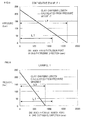
Fig. 5 is a graph showing a relation among a distance from an extrusion port in a drum of the conventional extrusion-forming device and a pressure and a clay charging length calculated from a pressure gradient; -
Fig. 6 is a graph showing a relation among a distance from an extrusion port in a drum of the extrusion-forming device of the present invention and the pressure and the clay charging length calculated from the pressure gradient; -
Fig. 7 is a graph showing a relation between a forming time of the conventional extrusion-forming device and the pressure; -
Fig. 8 is a graph showing a relation between the forming time of the conventional extrusion-forming device and an extrusion speed; -
Fig. 9 is a graph showing a relation between the forming time of the extrusion-forming device of the present invention and the pressure; -
Fig. 10 is a graph showing a relation between the forming time of the extrusion-forming device of the present invention and the extrusion speed; -
Fig. 11 is a schematic perspective view showing a honeycomb structure; and -
Fig. 12 is an explanatory view for explaining the clay charging length. - Hereinafter, embodiments of an extrusion-forming device and a method for manufacturing a formed article by use of the device of the present invention will be described in detail with reference to the drawings, but the present invention is not limited to the embodiments when interpreted, and various alterations, modifications and improvements can be added based on the knowledge of a person with ordinary skill without departing from the scope of the present invention.
-
Fig. 1 is a schematic constitution diagram showing an extrusion-formingdevice 100 in one embodiment of the present invention. As shown inFig. 1 , the extrusion-formingdevice 100 of the present invention has a constitution including anextruding portion 21 in which a clay containing a ceramic forming material is supplied from the outside and conveyed through the inside, and a formingportion 22 which extrudes the clay discharged from theextruding portion 21 to form a formed article. - Moreover, the
extruding portion 21 of the extrusion-formingdevice 100 in the embodiment of the present invention has adrum 7 including asupply port 19 through which the clay containing the ceramic forming material flows into the inside, ascrew 4 having arotary shaft 6 and a spiralrotary blade 5 disposed along therotary shaft 6 and configured to convey the clay in anextruding direction 8 parallel to therotary shaft 6 while kneading the clay by the rotation of therotary blade 5, and anextrusion port 20 through which the clay is discharged. - Furthermore, the forming
portion 22 of the extrusion-formingdevice 100 in the embodiment of the present invention has adie 1 through which the clay is extruded and which has forminggrooves 41 arranged in a formingface 40, and is arranged along theextruding direction 8 of the extrudingportion 21. - As shown in, for example,
Fig. 1 , thescrew 4 of the extrusion-formingdevice 100 in the embodiment of the present invention includes, as thescrew 4 on the side of thesupply port 19, at least two supplyport side screws 10 having supply port side rotary blades 55 provided so as to be rotationally symmetric with respect to therotary shaft 6 and, as the screw on the side of the extrusion port, at least one extrusion port side screw having an extrusion port side rotary blade, and a ratio P/D is in a range of 0.5 to 0.9, in which D is the diameter of the outermost periphery of the rotary blade, and P is the pitch of the extrusion port side rotary blade along the extruding direction. To increase the extrusion pressure, the pitch of the screw is decreased as compared with the conventional technology. If the ratio P/D is less than 0.5, a forwarding pitch is small, and the clay cannot be conveyed. Moreover, if the ratio P/D exceeds 0.9, the extrusion pressure cannot be obtained. - In the extrusion-forming
device 100 of the embodiment of the present invention, a ratio L2/L1 between a length L2 of the supplyport side screw 10 along theextruding direction 8 and a length L1 of an extrusionport side screw 12 along theextruding direction 8 is preferably from 1.33 to 2.50. Furthermore, the ratio L2/L1 is further preferably from 1.80 to 2.50. A reason for this is that it is necessary to provide a region to deaerate the clay which is being conveyed or a screw to knead the clay, and hence the length L2 of the supplyport side screw 10 along theextruding direction 8 needs to be from 4/7 to 5/7 of the whole screw length L. Moreover, the extrusion port side length L1 needs to be larger than a clay charging length L3 described later. In the embodiment, therefore, the length L1 is preferably as much as 12 to 18 pitches of the screw, that is, it is from 2/7 to 3/7 of the whole screw length. - In the extrusion-forming
device 100 of the embodiment of the present invention, since the extrusion port side length L1 needs to be larger than the clay charging length L3 described later, a ratio L1/L between the length L1 of the extrusionport side screw 12 along theextruding direction 8 and the length L of theextruding portion 21 along theextruding direction 8 is preferably from 0.29 to 0.43. - In the extrusion-forming device of the present invention, the
extruding portion 21 shown in, for example,Fig. 1 includes thedrum 7 including thesupply port 19 through which the clay containing the ceramic forming material flows into the inside, the screw having therotary shaft 6 and the spiralrotary blade 5 disposed along therotary shaft 6 and configured to convey the clay in the extruding direction parallel to the rotary shaft while kneading the clay by the rotation of the rotary blade, and the extrusion port through which the clay is discharged. - In the extrusion-forming device of the present invention, the inner length of the
drum 7 shown in, for example,Fig. 1 is preferably from 189 to 357 cm. Moreover, the inner diameter of thedrum 7 is preferably from 7.0 to 13.3 cm. - In the extrusion-forming device of the present invention, the
screw 4 includes the supply port side screws 10 on thesupply port 19 side and the extrusionport side screw 12 on theextrusion port 20 side. In the extrusion-forming device of the present invention, the whole length L of thescrew 4 shown in, for example,Fig. 1 is preferably from 189 to 357 cm. A diameter D of the outermost periphery of thescrew 4 is preferably from 7.0 to 13.3 cm. - In the extrusion-forming device of the present invention, for example, a diameter d1 of the
rotary shaft 6 is preferably from 4.5 to 8.6 cm. Thescrew 4 may be provided along one axis, or the screws may be provided along two axes in parallel. The screws are preferably provided along two axes in parallel, because the screws are excellent in an ability of kneading the clay. Thescrew 4 is provided with thespiral rotary blade 5 along therotary shaft 6. The screw includes at least two supply port side screws 10 having the supply port side rotary blades 55 provided as at least a part of therotary blade 5 on thesupply port 19 side so as to be rotationally symmetric with respect to therotary shaft 6, and at least one extrusionport side screw 12 having an extrusion port side rotary blade 56 provided as at least a part of therotary blade 5 on theextrusion port 20 side. Furthermore, in the extrusion-forming device of the present invention, a ratio P/D is in a range of 0.5 to 0.9, in which D is the diameter of the outermost periphery of therotary blade 5, and P is the pitch of the extrusion port side rotary blade 56 along the extrudingdirection 8. In the extrusion-forming device of the present embodiment, the ratio P/D is especially preferably in a range of 0.6 to 0.7. -
Fig. 4 is a schematic side view showing one example of the conventional extrusion port side screw 12 (the screw 4). As shown inFig. 4 , the one extrusion port side rotary blade 56 is provided. The length L1 of the extrusion port side rotary blade 56 along the extrudingdirection 8 is preferably from 54 to 108 cm, and the pitch of the extrusion port side rotary blade 56 is preferably from 9.0 to 18.0 cm.Fig. 3 is a schematic side view showing one example of the extrusion port side screw 12 (the screw 4) of the present invention. As shown inFig. 4 , anextrusion face 52 of the conventional extrusionport side screw 4 has an extrusion face tilt angle α as a tilt angle with respect to the center line of the screwrotary shaft 6 in a range of 35 to 55°. In the present invention, an extrusion face tilt angle α as a tilt angle of an extrusion face 51 with respect to the center line of the screwrotary shaft 6 is in a range of 60 to 80°. The extrusion face 51 has such an acute angle along the extrudingdirection 8, whereby an extrusion force exerted from the extrusion face in a normal line direction (seeFig. 3 for the present invention, seeFig. 4 for the conventional technology) works strongly in the extrudingdirection 8, thereby producing an effect of increasing a clay conveyance force. - The two supply port side rotary blades 55 are provided so as to be rotationally symmetric with respect to the
rotary shaft 6. The length L2 along the extrudingdirection 8 is preferably from 135 to 255 cm, and the pitches of the supply port side rotary blades 55 are preferably from 9.0 to 18.0 cm. - In the extrusion-forming device of the present embodiment, a conversion screw 11 is preferably provided between the supply port side screws 10 and the extrusion
port side screw 12. The conversion screw 11 performs screw shape changeover smoothly and continuously between the two supply port side screws 10 and the one extrusionport side screw 12. One or two conversion screws are preferably provided in terms of pitch number. - In the extrusion-forming device of the present embodiment, a
rectification plate 3 is preferably provided at a position where the formingportion 22 comes in contact with thedrum 7. The rectification plate has a function of squeezing the clay to be extruded, thereby rectifying the clay so that the clay has a uniform flow on the downstream side from the position. The rectification plate has aslit 30 as an opening in a portion which comes in contact with theextrusion port 20, and the diameter of the opening of theslit 30 is preferably from 20 to 50 cm. - (Die): In a die used in the present embodiment, a slit width of each slit through which the clay is extruded as the formed article is preferably from 70 to 170 µm, especially preferably from 70 to 125 µm. When the slit width is in a range of 70 to 100 µm in the conventional extrusion-forming device, the clay charging length reaches the region of the supply port side screws 10 in the extruding portion in the drum, thereby causing the fluctuation or pulsation of the extrusion pressure or extrusion speed. However, in the extrusion-forming device of the present invention, the clay charging length can be kept in the region of the extrusion port side screw, whereby the fluctuation or pulsation of the extrusion pressure or extrusion speed can be suppressed. In this way, it becomes possible to correctly and efficiently manufacture a formed honeycomb article having compact cells with thinner walls which have been demanded in recent years. Moreover, in the die used in the present embodiment, a plurality of clay introduction holes are provided as introduction holes internally connected to the slits and configured to introduce the clay into the die, and the diameters thereof are preferably from 0.08 to 0.20 cm.
- In the manufacturing method of the formed article of the present invention, there is used the extrusion-forming device of the above embodiment provided with the plurality of clay introduction ports through which the clay is introduced toward the supply port side of the die and provided with the forming grooves connected to the clay introduction ports in the die. The method includes a clay supply process of introducing the clay into the drum through the supply port and rotating the screw to convey the clay in the extruding direction while kneading the clay; and a clay forming process of discharging the clay supplied in the clay supply process to the forming portion through the extrusion port while keeping a state of L3 < L1, in which L3 is a clay charging length indicating a distance of a region where the clay is charged on the extrusion port side in the drum along the extruding direction, to set the extrusion pressure of the clay through the extrusion-forming face to a range of 15 to 30 MPa and to set the fluctuation of the extrusion pressure to a range of ±0.0 to 0.5 MPa, thereby extrusion-forming the formed article. It is to be noted that in the present description, as to the unit of the pressure, a conversion value is 1 Pa = 10-5 bar.
- Hereinafter, the method for manufacturing the formed honeycomb article by use of the extrusion-forming device of the present invention will be described. There is not any special restriction on the clay, but, for example, a clay containing 72 mass% of ceramic material, 23 mass% of water, 5 mass% of methylcellulose and another additive or the like may be used.
- In the die used in the extrusion-forming device of the present invention, the slits (the forming grooves) through which the formed article of the clay is extrusion-formed have a honeycomb shape, and the formed honeycomb article is preferably extrusion-formed as the formed article.
- In the present description, the clay charging length L3 is a distance between the supply port side end of the region where the clay is charged in the extruding portion and the
extrusion port 20 along the extrudingdirection 8 in the clay forming process. As shown in, for example,Fig. 12 , the clay charging length L3 is the length of the region where the clay is charged in the drum along the extrudingdirection 8. - As to the clay charging length L3, the state of L3 < L1 is preferably kept, because it is possible to suppress the fluctuation or pulsation of the extrusion pressure or extrusion speed which has heretofore been a cause for the forming defect of the formed article, and consequently it is possible to form the formed article having compact cells with high forming precision and production efficiency.
- The clay charging length L3 is determined by the extrusion pressure and a pressure gradient (see
Figs. 5, 6 ). The extrusion pressure increases, when the die slit width is small (about from 70 to 90 µm) or when the amount of the clay to be supplied is large. Therefore, even with the same pressure gradient, when the slit width is small and the amount of the clay to be supplied is large, the extrusion pressure increases, and the clay charging length L3 increases, whereby the state becomes L3 > L1 sometimes. Moreover, the pressure gradient is determined by a ratio of the supply amount/the screw rotation speed. Even with the same extrusion pressure, when the screw rotation number decreases, the pressure gradient becomes moderate, and the clay charging length L3 increases. In consideration of these situations, conditions for satisfying L3 < L1 are shown in Table 1. A ratio L3/L1 between the clay charging length L3 and the length L1 is preferably from 0.5 to 1.0. -
[Table 1] Screw outermost periphery diameter (cm) 13.3 Supply amount (kg/hr) 300 to 1000 Screw rotation speed (rpm) 10 to 35 Die slit width (µm) 70 or more Supply amount/screw rotation speed 25 to 35 Die opening diameter (cm) 13 - The extrusion pressure is the pressure of the clay measured at the extrusion port in the clay forming process. In the method for manufacturing the formed article by use of the extrusion-forming device of the present invention, the extrusion pressure is preferably in a range of 150 to 300 bar (15 to 30 MPa), and the fluctuation thereof is in a range of preferably ±0.0 to 0.5 MPa, especially preferably ±0.0 to 0.3 MPa.
- The extrusion speed is a discharge amount cm/s of the formed honeycomb article at the extrusion port per second. In the method for forming the formed article by use of the extrusion-forming device of the present invention, the extrusion speed is preferably from 1.0 to 6.0 cm/s and the fluctuation thereof is in a range of ±0.2 cm/s.
- The forming time is a time elapsed after the clay is supplied to the extrusion-forming device and the formed article starts to be extrusion-formed through the die.
- As a method for measuring the fluctuation of the pressure with respect to the forming time, the following method was used. For example, in the
drum 7 ofFig. 1 , general-purpose pressure sensors are attached, with an equal space therebetween in the direction of a rotaryshaft center line 9, to an attachment hole extending through the inner wall of thedrum 7 and exposed between biaxial screws in a direction vertical to the rotaryshaft center line 9 of thescrew 4. In the measurement method, the pressure sensors are connected to a recording meter (a data logger), and the numeric values of the pressure sensors are recorded in real time. - As a method for measuring the fluctuation of the speed with respect to the forming time, the following method was used. A speed sensor is provided in a direction vertical to the extruding
direction 8 of the formed article, the speed sensor is connected to the recording meter in the same manner as described above, and the numeric value of the speed sensor is recorded in real time. - In the extrusion-forming device of the present invention, as to a structure other than the screws, the conventional structure of the extrusion-forming device can basically be employed as it is. In the extrusion-forming device of the present invention, two screws in the drum may rotate in the same direction or different directions. Moreover, the number of the screws may be one or two.
- There is not any special restriction on the shape of the formed article by the extrusion-forming device of the present invention as long as the shape can be obtained by extrusion forming. However, the present invention is suitable for the forming of, for example, the formed honeycomb article in which the partition walls to partition the cells are thin and are easily deformed.
- In Example 1, Comparative Example 1, extrusion-forming devices were used, respectively. Each of the devices had conditions of D, P and W shown in Table 1, and included
screws 4 disposed along two axes in parallel and including two supply port side screws 10 having the supply port side rotary blades 55, one extrusionport side screw 12 having the extrusion port side rotary blade 56 and a conversion screw 11 sandwiched between the supply port side screws 10 and the extrusionport side screw 12 and configured to continuously convert a screw shape from the two screws into the one screw. The supply port side screws 10 having the same conditions were used in Comparative Example 1 and Example 1. A side view of an extrusion-formingdevice 100 of Example 1 is shown inFig. 1 . Furthermore,Fig. 3 is a partially enlarged side view of the screw 4 (the extrusion port side screw 12). Part dimensions are shown in Table 2. - A side view of an extrusion-forming
device 101 of Comparative Example 1 is shown inFig. 2 . Furthermore,Fig. 4 is a partially enlarged side view of a screw 4 (an extrusion port side screw 12). Part dimensions are shown in Table 2. - As shown in
Figs. 1, 2 , thescrews 4 of Example 1 or Comparative Example 1 were arranged along two axes in parallel in an extrudingportion 21 in the internal space of adrum 7 having the same shape. Furthermore, in thedrum 7, from anextrusion port 20 side, the extrusionport side screw 12, the conversion screw 11 and the supply port side screws 10 were arranged in order as thescrew 4. Before theextrusion port 20, a formingportion 22 provided with a die 40 was arranged. Part dimensions are shown in Table 2. -

- As to a die, there was used a die including honeycomb-like forming groove having a forming groove (slit) width of 75 µm in a forming face thereof, and a plurality of introduction holes provided on the face thereof opposite to the forming face and connected to the forming grooves in the die. The die having the same conditions was provided at the tip of the forming portion, in the extruding
direction 8, of the extrusion-forming device of each of Comparative Example 1 and Example 1, and the extrusion-forming of the clay containing the ceramic forming material was performed. The other operating conditions of the extrusion-forming device at this time are shown in Table 3. -
[Table 3] Screw outermost periphery diameter (cm) 13.3 Supply amount (kg/hr) 600 Screw rotation speed (rpm) 20 Die slit width (µm) 75 Die opening diameter (cm) 13 - Moreover, graphs of the extrusion pressure at the
extrusion port 20 of the extrusion-formingdevice 100 of Example 1 and the extrusion speed of the clay with respect to the forming time are shown inFigs. 9 and 10 , respectively. Furthermore, graphs of the extrusion pressure at theextrusion port 20 of the extrusion-formingdevice 101 of Comparative Example 1 and the extrusion speed of the clay with respect to the forming time are shown inFigs. 7 and 8 , respectively. - As shown in
Figs. 7, 8 , in Comparative Example 1, the extrusion pressure and the extrusion speed cause pulsation. Moreover, at this time, the fluctuation of the extrusion pressure was ±8.5 bar, and the fluctuation of the extrusion speed was ±5.6 mm/s. - As shown in
Figs. 9, 10 , in Example 1, the pulsation which occurred in Comparative Example 1 was suppressed. At this time, the fluctuation of the extrusion pressure was ±1.5 bar, and the fluctuation of the extrusion speed was ±1.0 mm/s. When the formed honeycomb article manufactured in this manner was fired, it was possible to obtain a honeycomb structure which did not have any defect. - The extrusion-forming device of the present invention can preferably be applied to the manufacturing of the formed article of the clay containing the ceramic material, especially the formed article having a ceramic honeycomb structure, and has a high industrial use possibility. Moreover, it is possible to manufacture the formed article having the honeycomb structure having a plurality of compact cells with thinner walls with a good efficiency and a high productivity, and the present invention has a remarkably high industrial use possibility.
- 1: die, 2: screen, 3: rectification plate, 4: screw, 5: rotary blade, 6: rotary shaft, 7: drum, 8: extruding direction, 9: rotary shaft center line direction, 10: supply port side screw, 11: conversion screw, 12: extrusion port side screw, 19: supply port, 20: extrusion port, 21: extruding portion, 22: forming portion, 30: opening, 40: forming groove (slit), 45: region where clay is charged, 51: rotary blade extrusion face, 52: rotary blade extrusion face, 55: supply port side rotary blade, 56: extrusion port side rotary blade, 60: honeycomb structure, 61: partition wall, 62: cell, 63: outer wall, 100: extrusion-forming device, and 101: extrusion-forming device.
Claims (6)
- An extrusion-forming device comprising:an extruding portion having a drum including a supply port through which a clay containing a ceramic forming material flows into the inside, a screw having a rotary shaft and a spiral rotary blade disposed along the rotary shaft and configured to convey the clay in an extruding direction parallel to the rotary shaft while kneading the clay by the rotation of the rotary blade, and an extrusion port through which the clay is discharged; anda forming portion including a die through which the clay is extruded and which has forming grooves arranged in a forming face, and arranged along the extruding direction of the extruding portion,wherein the screw includes, as the screw on the side of the supply port, at least two supply port side screws having supply port side rotary blades provided so as to be rotationally symmetric with respect to the rotary shaft and, as the screw on the side of the extrusion port, at least one extrusion port side screw having an extrusion port side rotary blade, anda ratio P/D is in a range of 0.5 to 0.9, in which D is the diameter of the outermost periphery of the rotary blade, and P is the pitch of the extrusion port side rotary blade along the extruding direction.
- The extrusion-forming device according to claim 1, wherein a ratio L2/L1 between a length L2 of the supply port side screw along the extruding direction and a length L1 of the extrusion port side screw along the extruding direction is in a range of 1.33 to 2.50.
- The extrusion-forming device according to claim 1 or 2, wherein a ratio L1/L between the length L1 of the extrusion port side screw along the extruding direction and a length L of the extruding portion along the extruding direction is in a range of 0.29 to 0.43.
- The extrusion-forming device according to any one of claims 1 to 3, wherein the screws are provided along two axes in parallel in the drum.
- A method for manufacturing a formed article by use of the extrusion-forming device according to any one of claims 1 to 4, comprising:a clay supply process of introducing the clay into the drum through the supply port and rotating the screw to convey the clay in the extruding direction while kneading the clay; anda clay forming process of discharging the clay supplied in the clay supply process to the forming portion through the extrusion port while keeping a state of L3 < L1, in which L3 is a clay charging length indicating a distance of a region where the clay is charged on the extrusion port side in the drum along the extruding direction, to set the extrusion pressure of the clay through the extrusion-forming face to a range of 15 to 30 MPa and to set the fluctuation of the extrusion pressure to a range of 0.1 to 1.0 MPa, thereby extrusion-forming the formed article.
- The method for manufacturing the formed honeycomb article according to claim 5, wherein the forming grooves have a honeycomb shape, and a formed honeycomb article is extrusion-formed as the formed article.
Priority Applications (1)
| Application Number | Priority Date | Filing Date | Title |
|---|---|---|---|
| PL10250359T PL2233265T3 (en) | 2009-03-25 | 2010-03-01 | Extrusion-forming device and method for manufacturing formed article by use of the device |
Applications Claiming Priority (1)
| Application Number | Priority Date | Filing Date | Title |
|---|---|---|---|
| JP2009073958A JP4805372B2 (en) | 2009-03-25 | 2009-03-25 | Extrusion molding apparatus and method for producing molded body using the same |
Publications (3)
| Publication Number | Publication Date |
|---|---|
| EP2233265A2 true EP2233265A2 (en) | 2010-09-29 |
| EP2233265A3 EP2233265A3 (en) | 2012-06-06 |
| EP2233265B1 EP2233265B1 (en) | 2013-12-18 |
Family
ID=42340852
Family Applications (1)
| Application Number | Title | Priority Date | Filing Date |
|---|---|---|---|
| EP10250359.6A Active EP2233265B1 (en) | 2009-03-25 | 2010-03-01 | Extrusion-forming device and method for manufacturing formed article by use of the device |
Country Status (4)
| Country | Link |
|---|---|
| US (1) | US9174357B2 (en) |
| EP (1) | EP2233265B1 (en) |
| JP (1) | JP4805372B2 (en) |
| PL (1) | PL2233265T3 (en) |
Cited By (3)
| Publication number | Priority date | Publication date | Assignee | Title |
|---|---|---|---|---|
| CN105050781A (en) * | 2013-03-21 | 2015-11-11 | 日本碍子株式会社 | Continuous Extrusion Forming Device |
| WO2019070797A1 (en) * | 2017-10-05 | 2019-04-11 | Corning Incorporated | Screw elements for extrusion apparatus and methods of manufacturing a honeycomb body |
| US11571832B2 (en) | 2017-10-05 | 2023-02-07 | Corning Incorporated | Kneading elements for extrusion apparatus and methods of manufacturing a honeycomb body |
Families Citing this family (4)
| Publication number | Priority date | Publication date | Assignee | Title |
|---|---|---|---|---|
| JP2012197186A (en) * | 2011-03-18 | 2012-10-18 | Ngk Insulators Ltd | Method for manufacturing honeycomb structure |
| WO2014148401A1 (en) | 2013-03-19 | 2014-09-25 | 日本碍子株式会社 | Extrusion molding device and extrusion molding method |
| WO2021191978A1 (en) * | 2020-03-23 | 2021-09-30 | 日本碍子株式会社 | Methods for manufacturing ceramic molding and ceramic structure |
| CN117601492B (en) * | 2023-12-05 | 2024-04-30 | 山东东源新材料科技有限公司 | Desulfurization and denitrification catalyst shaping equipment and shaping method |
Citations (1)
| Publication number | Priority date | Publication date | Assignee | Title |
|---|---|---|---|---|
| JP2008137184A (en) | 2006-11-30 | 2008-06-19 | Denso Corp | Ceramic molded body extrusion molding apparatus and molding method using the same |
Family Cites Families (12)
| Publication number | Priority date | Publication date | Assignee | Title |
|---|---|---|---|---|
| GB1239417A (en) * | 1967-09-01 | 1971-07-14 | ||
| JPS508725B1 (en) * | 1970-10-22 | 1975-04-07 | ||
| DE2446436A1 (en) * | 1974-09-28 | 1976-04-08 | Bayer Ag | MULTI-SHAFT SCREW MACHINE |
| DE2854207C3 (en) | 1978-12-15 | 1984-06-20 | Basf Ag, 6700 Ludwigshafen | Screw extruder for the continuous preparation of plasticizable masses |
| AT371058B (en) * | 1980-11-10 | 1983-05-25 | Maplan Masch Tech Anlagen | DOUBLE SCREW PRESS |
| US4994223A (en) | 1989-06-16 | 1991-02-19 | Bomatic, Inc. | Extruder screw and method for the extrusion of thermally sensitive thermoplastic materials |
| JPH09104056A (en) | 1995-10-12 | 1997-04-22 | Niigata Eng Co Ltd | Plastic processing screw |
| JP4670173B2 (en) | 2000-05-12 | 2011-04-13 | 株式会社デンソー | Extrusion equipment |
| JP4158472B2 (en) * | 2002-10-01 | 2008-10-01 | 株式会社デンソー | Ceramic molding extrusion equipment |
| US20090166910A1 (en) | 2005-11-16 | 2009-07-02 | Geo2 Technologies, Inc. | System and Method for Twin Screw Extrusion of a Fibrous Porous Substrate |
| JP4909013B2 (en) * | 2006-11-01 | 2012-04-04 | 日本碍子株式会社 | Twin screw extruder |
| DE102007057613B4 (en) * | 2007-11-28 | 2014-05-22 | Kautex Maschinenbau Gmbh | Extruder screw for a screw extruder |
-
2009
- 2009-03-25 JP JP2009073958A patent/JP4805372B2/en active Active
-
2010
- 2010-02-19 US US12/708,565 patent/US9174357B2/en active Active
- 2010-03-01 PL PL10250359T patent/PL2233265T3/en unknown
- 2010-03-01 EP EP10250359.6A patent/EP2233265B1/en active Active
Patent Citations (1)
| Publication number | Priority date | Publication date | Assignee | Title |
|---|---|---|---|---|
| JP2008137184A (en) | 2006-11-30 | 2008-06-19 | Denso Corp | Ceramic molded body extrusion molding apparatus and molding method using the same |
Cited By (5)
| Publication number | Priority date | Publication date | Assignee | Title |
|---|---|---|---|---|
| CN105050781A (en) * | 2013-03-21 | 2015-11-11 | 日本碍子株式会社 | Continuous Extrusion Forming Device |
| CN105050781B (en) * | 2013-03-21 | 2017-02-15 | 日本碍子株式会社 | Continuous Extrusion Forming Device |
| WO2019070797A1 (en) * | 2017-10-05 | 2019-04-11 | Corning Incorporated | Screw elements for extrusion apparatus and methods of manufacturing a honeycomb body |
| US11571832B2 (en) | 2017-10-05 | 2023-02-07 | Corning Incorporated | Kneading elements for extrusion apparatus and methods of manufacturing a honeycomb body |
| US12076903B2 (en) | 2017-10-05 | 2024-09-03 | Corning Incorporated | Screw elements for extrusion apparatus and methods of manufacturing a honeycomb body |
Also Published As
| Publication number | Publication date |
|---|---|
| JP4805372B2 (en) | 2011-11-02 |
| US20100244308A1 (en) | 2010-09-30 |
| US9174357B2 (en) | 2015-11-03 |
| JP2010221637A (en) | 2010-10-07 |
| PL2233265T3 (en) | 2014-05-30 |
| EP2233265B1 (en) | 2013-12-18 |
| EP2233265A3 (en) | 2012-06-06 |
Similar Documents
| Publication | Publication Date | Title |
|---|---|---|
| US9174357B2 (en) | Extrusion-forming device | |
| US7594807B2 (en) | Twin-screw extruder | |
| US9375890B2 (en) | Extrusion-molding device and method for producing molded body using same | |
| JP5753005B2 (en) | Method for producing green molded body for honeycomb structure | |
| JP5753006B2 (en) | Extrusion molding apparatus and method for producing molded body using the same | |
| JP5686709B2 (en) | Extrusion molding apparatus and method for producing molded body using the same | |
| US8758004B2 (en) | Extruder | |
| JP2008137186A (en) | Ceramic molding extrusion equipment | |
| JP5785465B2 (en) | Extrusion molding apparatus and method for producing green molded body for honeycomb structure using the same | |
| US12097638B2 (en) | Extrusion molding machine and method for producing molded body | |
| US20200276745A1 (en) | Screw elements for extrusion apparatus and methods of manufacturing a honeycomb body | |
| JP5965748B2 (en) | Extrusion molding apparatus and method for producing molded body using the same | |
| JP2008126592A (en) | Pug mill | |
| JP6646003B2 (en) | Extrusion molding equipment | |
| WO2012169581A1 (en) | Die for molding honeycomb structure and method for producing honeycomb structure using same | |
| JP6790313B1 (en) | Manufacturing method of ceramic molded body and ceramic structure | |
| US9095993B2 (en) | Extrusion molding apparatus and manufacturing method for green honeycomb molded body using same | |
| WO2013125483A1 (en) | Method for inspecting honeycomb structure, method for producing honeycomb structure, honeycomb structure, method for designing sealing mask, and program for inspecting honeycomb structure | |
| JP2013193279A (en) | Extrusion molding device and method of manufacturing molding using the same |
Legal Events
| Date | Code | Title | Description |
|---|---|---|---|
| PUAI | Public reference made under article 153(3) epc to a published international application that has entered the european phase |
Free format text: ORIGINAL CODE: 0009012 |
|
| AK | Designated contracting states |
Kind code of ref document: A2 Designated state(s): AT BE BG CH CY CZ DE DK EE ES FI FR GB GR HR HU IE IS IT LI LT LU LV MC MK MT NL NO PL PT RO SE SI SK SM TR |
|
| AX | Request for extension of the european patent |
Extension state: AL BA ME RS |
|
| RIC1 | Information provided on ipc code assigned before grant |
Ipc: B28B 3/22 20060101AFI20120319BHEP |
|
| PUAL | Search report despatched |
Free format text: ORIGINAL CODE: 0009013 |
|
| AK | Designated contracting states |
Kind code of ref document: A3 Designated state(s): AT BE BG CH CY CZ DE DK EE ES FI FR GB GR HR HU IE IS IT LI LT LU LV MC MK MT NL NO PL PT RO SE SI SK SM TR |
|
| AX | Request for extension of the european patent |
Extension state: AL BA ME RS |
|
| RIC1 | Information provided on ipc code assigned before grant |
Ipc: B28B 3/22 20060101AFI20120503BHEP |
|
| 17P | Request for examination filed |
Effective date: 20121127 |
|
| GRAP | Despatch of communication of intention to grant a patent |
Free format text: ORIGINAL CODE: EPIDOSNIGR1 |
|
| INTG | Intention to grant announced |
Effective date: 20130705 |
|
| RIC1 | Information provided on ipc code assigned before grant |
Ipc: B29C 47/38 20060101ALI20130624BHEP Ipc: B29C 47/00 20060101ALI20130624BHEP Ipc: B30B 11/24 20060101ALI20130624BHEP Ipc: B29C 47/40 20060101ALI20130624BHEP Ipc: B28B 3/22 20060101AFI20130624BHEP |
|
| GRAS | Grant fee paid |
Free format text: ORIGINAL CODE: EPIDOSNIGR3 |
|
| GRAA | (expected) grant |
Free format text: ORIGINAL CODE: 0009210 |
|
| AK | Designated contracting states |
Kind code of ref document: B1 Designated state(s): AT BE BG CH CY CZ DE DK EE ES FI FR GB GR HR HU IE IS IT LI LT LU LV MC MK MT NL NO PL PT RO SE SI SK SM TR |
|
| REG | Reference to a national code |
Ref country code: GB Ref legal event code: FG4D |
|
| REG | Reference to a national code |
Ref country code: CH Ref legal event code: EP |
|
| REG | Reference to a national code |
Ref country code: AT Ref legal event code: REF Ref document number: 645408 Country of ref document: AT Kind code of ref document: T Effective date: 20140115 |
|
| REG | Reference to a national code |
Ref country code: IE Ref legal event code: FG4D |
|
| REG | Reference to a national code |
Ref country code: DE Ref legal event code: R096 Ref document number: 602010012494 Country of ref document: DE Effective date: 20140213 |
|
| REG | Reference to a national code |
Ref country code: NL Ref legal event code: VDEP Effective date: 20131218 |
|
| PG25 | Lapsed in a contracting state [announced via postgrant information from national office to epo] |
Ref country code: HR Free format text: LAPSE BECAUSE OF FAILURE TO SUBMIT A TRANSLATION OF THE DESCRIPTION OR TO PAY THE FEE WITHIN THE PRESCRIBED TIME-LIMIT Effective date: 20131218 Ref country code: SE Free format text: LAPSE BECAUSE OF FAILURE TO SUBMIT A TRANSLATION OF THE DESCRIPTION OR TO PAY THE FEE WITHIN THE PRESCRIBED TIME-LIMIT Effective date: 20131218 Ref country code: FI Free format text: LAPSE BECAUSE OF FAILURE TO SUBMIT A TRANSLATION OF THE DESCRIPTION OR TO PAY THE FEE WITHIN THE PRESCRIBED TIME-LIMIT Effective date: 20131218 Ref country code: LT Free format text: LAPSE BECAUSE OF FAILURE TO SUBMIT A TRANSLATION OF THE DESCRIPTION OR TO PAY THE FEE WITHIN THE PRESCRIBED TIME-LIMIT Effective date: 20131218 Ref country code: NO Free format text: LAPSE BECAUSE OF FAILURE TO SUBMIT A TRANSLATION OF THE DESCRIPTION OR TO PAY THE FEE WITHIN THE PRESCRIBED TIME-LIMIT Effective date: 20140318 |
|
| REG | Reference to a national code |
Ref country code: AT Ref legal event code: MK05 Ref document number: 645408 Country of ref document: AT Kind code of ref document: T Effective date: 20131218 |
|
| REG | Reference to a national code |
Ref country code: LT Ref legal event code: MG4D |
|
| PG25 | Lapsed in a contracting state [announced via postgrant information from national office to epo] |
Ref country code: LV Free format text: LAPSE BECAUSE OF FAILURE TO SUBMIT A TRANSLATION OF THE DESCRIPTION OR TO PAY THE FEE WITHIN THE PRESCRIBED TIME-LIMIT Effective date: 20131218 |
|
| REG | Reference to a national code |
Ref country code: PL Ref legal event code: T3 |
|
| PG25 | Lapsed in a contracting state [announced via postgrant information from national office to epo] |
Ref country code: EE Free format text: LAPSE BECAUSE OF FAILURE TO SUBMIT A TRANSLATION OF THE DESCRIPTION OR TO PAY THE FEE WITHIN THE PRESCRIBED TIME-LIMIT Effective date: 20131218 Ref country code: IS Free format text: LAPSE BECAUSE OF FAILURE TO SUBMIT A TRANSLATION OF THE DESCRIPTION OR TO PAY THE FEE WITHIN THE PRESCRIBED TIME-LIMIT Effective date: 20140418 Ref country code: BE Free format text: LAPSE BECAUSE OF FAILURE TO SUBMIT A TRANSLATION OF THE DESCRIPTION OR TO PAY THE FEE WITHIN THE PRESCRIBED TIME-LIMIT Effective date: 20131218 |
|
| PG25 | Lapsed in a contracting state [announced via postgrant information from national office to epo] |
Ref country code: NL Free format text: LAPSE BECAUSE OF FAILURE TO SUBMIT A TRANSLATION OF THE DESCRIPTION OR TO PAY THE FEE WITHIN THE PRESCRIBED TIME-LIMIT Effective date: 20131218 Ref country code: PT Free format text: LAPSE BECAUSE OF FAILURE TO SUBMIT A TRANSLATION OF THE DESCRIPTION OR TO PAY THE FEE WITHIN THE PRESCRIBED TIME-LIMIT Effective date: 20140418 Ref country code: AT Free format text: LAPSE BECAUSE OF FAILURE TO SUBMIT A TRANSLATION OF THE DESCRIPTION OR TO PAY THE FEE WITHIN THE PRESCRIBED TIME-LIMIT Effective date: 20131218 Ref country code: SK Free format text: LAPSE BECAUSE OF FAILURE TO SUBMIT A TRANSLATION OF THE DESCRIPTION OR TO PAY THE FEE WITHIN THE PRESCRIBED TIME-LIMIT Effective date: 20131218 Ref country code: ES Free format text: LAPSE BECAUSE OF FAILURE TO SUBMIT A TRANSLATION OF THE DESCRIPTION OR TO PAY THE FEE WITHIN THE PRESCRIBED TIME-LIMIT Effective date: 20131218 Ref country code: RO Free format text: LAPSE BECAUSE OF FAILURE TO SUBMIT A TRANSLATION OF THE DESCRIPTION OR TO PAY THE FEE WITHIN THE PRESCRIBED TIME-LIMIT Effective date: 20131218 Ref country code: CY Free format text: LAPSE BECAUSE OF FAILURE TO SUBMIT A TRANSLATION OF THE DESCRIPTION OR TO PAY THE FEE WITHIN THE PRESCRIBED TIME-LIMIT Effective date: 20131218 Ref country code: CZ Free format text: LAPSE BECAUSE OF FAILURE TO SUBMIT A TRANSLATION OF THE DESCRIPTION OR TO PAY THE FEE WITHIN THE PRESCRIBED TIME-LIMIT Effective date: 20131218 |
|
| REG | Reference to a national code |
Ref country code: DE Ref legal event code: R097 Ref document number: 602010012494 Country of ref document: DE |
|
| PLBE | No opposition filed within time limit |
Free format text: ORIGINAL CODE: 0009261 |
|
| STAA | Information on the status of an ep patent application or granted ep patent |
Free format text: STATUS: NO OPPOSITION FILED WITHIN TIME LIMIT |
|
| PG25 | Lapsed in a contracting state [announced via postgrant information from national office to epo] |
Ref country code: DK Free format text: LAPSE BECAUSE OF FAILURE TO SUBMIT A TRANSLATION OF THE DESCRIPTION OR TO PAY THE FEE WITHIN THE PRESCRIBED TIME-LIMIT Effective date: 20131218 Ref country code: LU Free format text: LAPSE BECAUSE OF FAILURE TO SUBMIT A TRANSLATION OF THE DESCRIPTION OR TO PAY THE FEE WITHIN THE PRESCRIBED TIME-LIMIT Effective date: 20140301 |
|
| REG | Reference to a national code |
Ref country code: CH Ref legal event code: PL |
|
| 26N | No opposition filed |
Effective date: 20140919 |
|
| GBPC | Gb: european patent ceased through non-payment of renewal fee |
Effective date: 20140318 |
|
| REG | Reference to a national code |
Ref country code: IE Ref legal event code: MM4A Ref country code: DE Ref legal event code: R097 Ref document number: 602010012494 Country of ref document: DE Effective date: 20140919 |
|
| PG25 | Lapsed in a contracting state [announced via postgrant information from national office to epo] |
Ref country code: GB Free format text: LAPSE BECAUSE OF NON-PAYMENT OF DUE FEES Effective date: 20140318 Ref country code: LI Free format text: LAPSE BECAUSE OF NON-PAYMENT OF DUE FEES Effective date: 20140331 Ref country code: CH Free format text: LAPSE BECAUSE OF NON-PAYMENT OF DUE FEES Effective date: 20140331 Ref country code: IE Free format text: LAPSE BECAUSE OF NON-PAYMENT OF DUE FEES Effective date: 20140301 |
|
| PG25 | Lapsed in a contracting state [announced via postgrant information from national office to epo] |
Ref country code: SI Free format text: LAPSE BECAUSE OF FAILURE TO SUBMIT A TRANSLATION OF THE DESCRIPTION OR TO PAY THE FEE WITHIN THE PRESCRIBED TIME-LIMIT Effective date: 20131218 |
|
| REG | Reference to a national code |
Ref country code: FR Ref legal event code: PLFP Year of fee payment: 7 |
|
| PG25 | Lapsed in a contracting state [announced via postgrant information from national office to epo] |
Ref country code: MT Free format text: LAPSE BECAUSE OF FAILURE TO SUBMIT A TRANSLATION OF THE DESCRIPTION OR TO PAY THE FEE WITHIN THE PRESCRIBED TIME-LIMIT Effective date: 20131218 |
|
| PG25 | Lapsed in a contracting state [announced via postgrant information from national office to epo] |
Ref country code: SM Free format text: LAPSE BECAUSE OF FAILURE TO SUBMIT A TRANSLATION OF THE DESCRIPTION OR TO PAY THE FEE WITHIN THE PRESCRIBED TIME-LIMIT Effective date: 20131218 |
|
| PG25 | Lapsed in a contracting state [announced via postgrant information from national office to epo] |
Ref country code: MC Free format text: LAPSE BECAUSE OF FAILURE TO SUBMIT A TRANSLATION OF THE DESCRIPTION OR TO PAY THE FEE WITHIN THE PRESCRIBED TIME-LIMIT Effective date: 20131218 |
|
| PG25 | Lapsed in a contracting state [announced via postgrant information from national office to epo] |
Ref country code: GR Free format text: LAPSE BECAUSE OF FAILURE TO SUBMIT A TRANSLATION OF THE DESCRIPTION OR TO PAY THE FEE WITHIN THE PRESCRIBED TIME-LIMIT Effective date: 20140319 Ref country code: BG Free format text: LAPSE BECAUSE OF FAILURE TO SUBMIT A TRANSLATION OF THE DESCRIPTION OR TO PAY THE FEE WITHIN THE PRESCRIBED TIME-LIMIT Effective date: 20131218 Ref country code: IT Free format text: LAPSE BECAUSE OF FAILURE TO SUBMIT A TRANSLATION OF THE DESCRIPTION OR TO PAY THE FEE WITHIN THE PRESCRIBED TIME-LIMIT Effective date: 20131218 |
|
| PG25 | Lapsed in a contracting state [announced via postgrant information from national office to epo] |
Ref country code: TR Free format text: LAPSE BECAUSE OF FAILURE TO SUBMIT A TRANSLATION OF THE DESCRIPTION OR TO PAY THE FEE WITHIN THE PRESCRIBED TIME-LIMIT Effective date: 20131218 Ref country code: HU Free format text: LAPSE BECAUSE OF FAILURE TO SUBMIT A TRANSLATION OF THE DESCRIPTION OR TO PAY THE FEE WITHIN THE PRESCRIBED TIME-LIMIT; INVALID AB INITIO Effective date: 20100301 |
|
| REG | Reference to a national code |
Ref country code: FR Ref legal event code: PLFP Year of fee payment: 8 |
|
| REG | Reference to a national code |
Ref country code: FR Ref legal event code: PLFP Year of fee payment: 9 |
|
| PG25 | Lapsed in a contracting state [announced via postgrant information from national office to epo] |
Ref country code: MK Free format text: LAPSE BECAUSE OF FAILURE TO SUBMIT A TRANSLATION OF THE DESCRIPTION OR TO PAY THE FEE WITHIN THE PRESCRIBED TIME-LIMIT Effective date: 20131218 |
|
| PGFP | Annual fee paid to national office [announced via postgrant information from national office to epo] |
Ref country code: DE Payment date: 20260128 Year of fee payment: 17 |
|
| PGFP | Annual fee paid to national office [announced via postgrant information from national office to epo] |
Ref country code: FR Payment date: 20260209 Year of fee payment: 17 |
|
| PGFP | Annual fee paid to national office [announced via postgrant information from national office to epo] |
Ref country code: PL Payment date: 20260213 Year of fee payment: 17 |