EP2233228A1 - Method of producing a fine grain casting - Google Patents
Method of producing a fine grain casting Download PDFInfo
- Publication number
- EP2233228A1 EP2233228A1 EP10250284A EP10250284A EP2233228A1 EP 2233228 A1 EP2233228 A1 EP 2233228A1 EP 10250284 A EP10250284 A EP 10250284A EP 10250284 A EP10250284 A EP 10250284A EP 2233228 A1 EP2233228 A1 EP 2233228A1
- Authority
- EP
- European Patent Office
- Prior art keywords
- chamber
- magnetic field
- mold
- opening
- susceptor
- Prior art date
- Legal status (The legal status is an assumption and is not a legal conclusion. Google has not performed a legal analysis and makes no representation as to the accuracy of the status listed.)
- Granted
Links
- 238000005266 casting Methods 0.000 title claims abstract description 8
- 238000000034 method Methods 0.000 title claims description 10
- 239000012768 molten material Substances 0.000 claims abstract description 31
- 230000006698 induction Effects 0.000 claims abstract description 20
- 238000003760 magnetic stirring Methods 0.000 claims abstract description 8
- 238000007711 solidification Methods 0.000 claims description 20
- 230000008023 solidification Effects 0.000 claims description 20
- 238000004804 winding Methods 0.000 claims description 15
- 238000003756 stirring Methods 0.000 claims description 14
- 230000007423 decrease Effects 0.000 claims description 11
- 230000003247 decreasing effect Effects 0.000 claims description 9
- 238000001816 cooling Methods 0.000 claims description 6
- 230000004323 axial length Effects 0.000 claims description 4
- 230000001939 inductive effect Effects 0.000 description 24
- 239000007769 metal material Substances 0.000 description 5
- 239000012530 fluid Substances 0.000 description 4
- 239000002184 metal Substances 0.000 description 4
- 230000000903 blocking effect Effects 0.000 description 3
- 239000000463 material Substances 0.000 description 3
- 230000000712 assembly Effects 0.000 description 2
- 238000000429 assembly Methods 0.000 description 2
- 230000004048 modification Effects 0.000 description 2
- 238000012986 modification Methods 0.000 description 2
- OKTJSMMVPCPJKN-UHFFFAOYSA-N Carbon Chemical compound [C] OKTJSMMVPCPJKN-UHFFFAOYSA-N 0.000 description 1
- 230000015572 biosynthetic process Effects 0.000 description 1
- 238000006243 chemical reaction Methods 0.000 description 1
- 239000002826 coolant Substances 0.000 description 1
- 239000013078 crystal Substances 0.000 description 1
- 230000001419 dependent effect Effects 0.000 description 1
- 230000002349 favourable effect Effects 0.000 description 1
- 229910002804 graphite Inorganic materials 0.000 description 1
- 239000010439 graphite Substances 0.000 description 1
- 239000007770 graphite material Substances 0.000 description 1
- 238000010438 heat treatment Methods 0.000 description 1
- 238000009413 insulation Methods 0.000 description 1
- 230000035515 penetration Effects 0.000 description 1
- XLYOFNOQVPJJNP-UHFFFAOYSA-N water Substances O XLYOFNOQVPJJNP-UHFFFAOYSA-N 0.000 description 1
Images


Classifications
-
- B—PERFORMING OPERATIONS; TRANSPORTING
- B22—CASTING; POWDER METALLURGY
- B22D—CASTING OF METALS; CASTING OF OTHER SUBSTANCES BY THE SAME PROCESSES OR DEVICES
- B22D27/00—Treating the metal in the mould while it is molten or ductile ; Pressure or vacuum casting
- B22D27/04—Influencing the temperature of the metal, e.g. by heating or cooling the mould
- B22D27/045—Directionally solidified castings
-
- B—PERFORMING OPERATIONS; TRANSPORTING
- B22—CASTING; POWDER METALLURGY
- B22D—CASTING OF METALS; CASTING OF OTHER SUBSTANCES BY THE SAME PROCESSES OR DEVICES
- B22D27/00—Treating the metal in the mould while it is molten or ductile ; Pressure or vacuum casting
- B22D27/02—Use of electric or magnetic effects
Definitions
- This disclosure generally relates to a method and device for directional solidification of a cast part. More particularly, this disclosure relates to a directional solidification casting process that varies magnetic stirring to provide a desired grain structure.
- a directional solidification (DS) casting process is utilized to orientate grain structure within a cast part.
- the desired orientation is provided by moving a mold from a hot zone within a furnace into a cooler zone at a desired rate. As the mold moves into the cooler zone, the molten material solidifies along a solidification front in one direction.
- Mixing of the molten material within the furnace is known to produce a desired grain size.
- Such mixing can be induced in the molten metal material by a magnetic field generated from a coil encircling the furnace cavity.
- an induction furnace utilizes an electric coil that produces heat required for maintaining the metal in a molten state. Insulation is utilized to retain heat within the furnace cavity and a susceptor is utilized to block any magnetic field produced by the electric coil. When magnetic mixing is desired the susceptor is eliminated.
- a minimum level of current is required to produce the heat required to maintain the metal in a molten state.
- the current level also controls the strength of the magnetic field.
- the levels required to maintain heat may not provide the desired strength of the magnetic field. Accordingly, it is desirable to design and develop a method and device for controlling the strength of the magnetic field acting on the molten material separate from the heating function of the inductive coil.
- a disclosed induction heated furnace assembly for producing a directionally solidified casting includes a susceptor that tailors strength of the magnetic field within the chamber to provide a desired grain structure in a completed cast part.
- the example susceptor proportionally blocks portions of the magnetic field to provide different levels of magnetic stirring within the molten material within the mold. Stirring induced by the magnetic field is reduced in a direction towards the opening of the chamber through which a cast article is removed in the directional solidification process to create the desired grain structures in the completed cast article.
- an example induction furnace assembly 10 includes a chamber 12 that includes an opening 14 through which a mold 32 is received and withdrawn.
- the chamber 12 is isolated from the external environment by insulated walls 16.
- An inductive coil 18 generates heat, indicated by arrows 50, to maintain metal 34 within the mold 32 at a desired temperature.
- the example furnace assembly includes a susceptor 22 that blocks a portion of a magnetic field (schematically shown at 52) that is generated by the inductive coil 18.
- the example susceptor 22 is a wall that surrounds the chamber 12 and is made of a graphite material.
- the susceptor 22 is fabricated from material such as graphite that blocks the penetration of the magnetic field 52 produced by the inductive coil 18.
- the susceptor 22 can also provide for the translation of energy from the magnetic field into heat energy, as indicated at arrows 50 to further maintain a temperature within the mold 32.
- molten metal material 34 is disposed in the mold 32 and supported on a support 38.
- the example support 38 includes a chill plate 40 that both supports the mold 32 and includes cooling features to aid in cooling the molten material 34.
- the inductive coil 18 receives electrical energy from an electric power source schematically indicated at 44. This electrical energy is provided at a desired current level determined to provide sufficient power and energy to create the desired temperature within the chamber 12 that maintains the molten metal 34 in a molten state.
- the example inductive coil 18 comprises a plurality of electrically conductive hollow tubes 20.
- the plurality of tubes 20 also provide for the circulation of a fluid that is generated by a pump 46 that supplies fluid from a fluid source 48 to flow through the tubes 20.
- a directional solidification casting process is utilized where molten material is poured into the mold 32 within the chamber 12 at a desired temperature to maintain the molten material in a molten state.
- the support 38 is then lowered through the opening 14 out of the hot chamber 12.
- the mold 32 is lowered from the chamber 12 at a desired rate to cool the molten material in a controlled manner to produce desired columnar structure.
- the controlled cooling produces a solidification front within the molten material 34.
- the completed cast part is desired to include a specific grain structure and size.
- the size and structure of grains within the completed cast part provide desired material characteristics and performance, such as for example material fatigue performance. In many applications, the finer the grain size the more favorable the performance of the completed cast article.
- the example furnace assembly 10 includes the susceptor 22 with a varying thickness to block a proportionate amount of the magnetic field 52. The proportional blocking of the magnetic field 52 generates a proportional amount of magnetic stirring within the molten metal material 34.
- the generated magnetic field 52 produces currents within the molten metal material that interact with the molten metal material 34 to provide stirring and mixing to break up large grain nuclei to form smaller grain structures.
- the susceptor is sized to include a thickness that is thick enough to completely eliminate the generation of any magnetic field within the hot zone of the chamber 12.
- the example furnace 10 includes a susceptor of a varying thickness such that it can vary the strength of the magnetic field 52 depending on the position of the mold 32 within the chamber 12. In this way a variable stirring can be induced within the molten material to break up the larger grain structures to form smaller and more desirable grains in a completed part.
- the example susceptor 22 includes a first thickness 28 disposed at a portion closest to the opening 14.
- the susceptor 22 also includes a second thickness 30 that is disposed at an end opposite the opening 14. The second thickness 30 is much less then the first thickness 28 to allow the largest portion of the magnetic field 52 to pass into and create stirring.
- the example structure of the susceptor 22 provides for the generation of a strongest magnetic field point indicated by 54 and a weakest magnetic field point indicated at 56. Note that points 54 and 56 represent an area or region within the chamber 12 where the magnetic field 52 is at a greatest or weakest strength.
- the example susceptor '22 includes the wall that is sloped at an angle 62 between the first thickness 28 and the second thickness 30.
- the example susceptor 22 is disposed at a constant angle that provides a uniform increase in thickness in a direction towards the opening 14.
- the steady increase in the thickness of the susceptor 22 in a direction towards the opening 14 provides for the steady decrease in magnetic field strength generated within the chamber 12.
- the decrease in the magnetic field strength towards the opening 14 produces a decrease in stirring and mixing encountered within the molten material 34.
- the example furnace 10 is illustrated with the mold 32 partially removed from the hot chamber 12. As the mold 32 is removed, a solidification front 58 is formed within the molten material 34. Mixing at the solidification front does not provide the desired fine grain structure and can disrupt any desired columnar structures, and therefore in some instances it can be desirable to reduce the amount of magnetic mixing along the solidification front 58.
- the example induction furnace 10 reduces the magnitude of the magnetic field 52 in a direction towards the opening 14 such that as the mold 32 is withdrawn from the hot chamber 12, mixing is slowly reduced until such mixing is completely stopped at a point where the solidification front 58 is formed.
- the molten material 34 remains above the solidification front 58 and a solidified portion of the desired cast part 60 extends downward from the solidification front 58.
- the solidification front 58 remains substantially stationary relative to the opening 14 as the mold 32 is moved downwardly and out of the chamber 12.
- This process may also be utilized in concert with a single crystal seed 36 or can use other directional solidification processes to create the desired grain structure.
- the amount of magnetic stirring can be tailored to provide varying amounts of mixing to induce formation of the desired grain structure in a completed part.
- the furnace 10 is brought up to a desired temperature by providing a sufficient current from the electric power source 44 to the inductive coil 18.
- Water supplied from the pump 46 and fluid source 48 is pumped through the plurality of tubes 20 that make up the inductive coil 18.
- the heat 50 created by the inductive coil 12 and also created by a partial conversion of the magnetic field by the susceptor 22 heats the chamber 12 to a desired temperature.
- molten material 34 is poured into the mold 32.
- the mold 32 defines the external shape and features of the completed cast article.
- a seed 36 is placed within the mold 32 to further orientate the desired grain structure of the completed cast article.
- the mold 32 is placed on a support 38.
- the support 38 is movable in a direction axially into and out of the chamber 12.
- Support 38 also includes the chill plate 40 that is supplied with a coolant to maintain a desired cooling temperature to encourage cooling in a uniform manner.
- the shape and thickness of the example susceptor 22 governs the strength of the magnetic field 52 by blocking a desired portion of that magnetic field generated by the inductive coil 18.
- the susceptor 22 includes the increasing thickness to proportionally block a greater amount of the magnetic field 52 in a direction toward the opening 14. At the top most portion of the chamber 12, where the magnetic field 52 is at the greatest strength the susceptor 22 is at its smallest thickness 30.
- the susceptor thicknesses can be adapted to provide the specific magnetic field and stirring properties required to provide the desired grain structure in the completed cast article.
- another example furnace assembly 70 includes a susceptor 72 that includes a plurality of openings 74.
- the plurality of openings provides for a portion of the magnetic field 52 generated by the inductive coils 18 to enter the chamber 12. Accordingly, the strength of the magnetic field 52 is proportionally controlled by the number and area of the openings within the susceptor 72.
- the susceptor 72 includes at least three zones of openings.
- a first zone 76 a large number of openings 74 are provided to allow the generation and strength of the magnetic field 52 to be at its greatest part.
- that zone is provided at the top most part of the chamber 12.
- a second or intermediate zone 78 is disposed between the first zone 76 and a third zone 80.
- This second zone 78 provides an intermediate level or strength of a magnetic field to find an intermediate mixing.
- the third zone 80 blocks a greater portion of the magnetic field 52 to provide the least amount of mixing and blocks most of the magnetic field 52 at a point where the magnetic field 52 within the chamber 12 is at its weakest as is indicated by 56.
- the openings 74 are disposed through the entire thickness of the susceptor 72 and provide for the proportional control of the magnitude of the strength of the magnetic field that is encountered within the chamber 12.
- the susceptor 90 of this example includes a large opening 96.
- the large opening 96 includes an area 100 that decreases in a direction towards the opening 14.
- the opening 96 is triangular shaped having the base or largest width portion disposed at a top most portion of the chamber 12.
- the sides 104 are disposed at an angle 102 that decreases to a point 98 and smallest area 94 in a direction towards the opening 14 such that the magnetic field 52 that is blocked from entering the chamber 12 increases in a direction towards the opening 14 and withdrawal of the mold from the furnace assembly 88.
- the example opening 96 includes the sides 104 disposed at a decreasing angle 102.
- This angle 102 is a uniform and constant to provide a proportional reduction in magnetic strength in a direction towards the opening 14.
- This decrease in the opening 96 provides for a change in area from a largest area 96 at the top most portion to a smaller area 94 at the bottom most portion.
- Decreasing area 100 of the opening 96 provides for the controlled reduction in the magnetic field 52 that is utilized for stirring molten material within the example furnace assembly 10.
- another furnace assembly 105 is illustrated and includes the opening 96.
- the opening 96 also includes a decreasing area 100.
- the opening 96 differs from the previous example in that the side 106 is at a non-uniform angle. This non-uniform angle is utilized to tailor the strength of the magnetic field 52 as it decreases from a greatest amount of magnetic strength to a least amount of magnetic strength.
- the shape of the opening 96 can be modified to tailor the magnetic field strength and thereby the amount of mixing of the molten material.
- the several different embodiments of the example inductive furnace assemblies all provide proportionate blocking of the magnetic field 52 to tailor the strength of the magnetic field based on a position of the mold to further tailor mixing and stirring of the molten material of the cast part.
- Other areas and shapes of opening can be utilized to block portions of the magnetic field that are to generate the desired stirring that provides the desired final grain structure in the cast article.
- another example induction furnace assembly 110 includes an inductive coil 112 that has a variable number of turns to tailor the strength of the magnetic field 52 produced with in the chamber 124.
- the example inductive coil 112 includes portions with different numbers of windings per axial distance. The number of windings for a given current supplied by the power source 44 creates a desired magnitude of the magnetic field 52 that is produced. Increasing or decreasing the number of windings changes the strength of the magnetic field 52 that is generated.
- the susceptor 120 includes a fixed thickness 122 for the entire axial length of the chamber 12.
- the inductive coil 112 includes three different zones each having different numbers of windings per axial length.
- the first set of windings 114 includes a high number of windings to produce the greatest strength of the magnetic field 52 within the chamber 12.
- a second number of turns 116 produce an intermediate magnetic field strength within the chamber 12.
- a third number 118 is smaller than both the second 116 and first 114 number of turns and produces the least amount of magnetic field strength.
- the least amount of magnetic field strength is provided by the group of windings 118 disposed at a lower portion of the furnace assembly 110.
- the modification of the inductive coil 112 provides the desired tailoring and proportional reduction in magnetic field strength within the chamber 12 desired to create variable mixing dependent on the axial position of the mold as it is being lowered from the furnace assembly 110.
- the induction coil 112 may comprise a plurality of windings or tubes wherein an inner diameter of the windings or tubes decreases in a direction towards the chamber opening.
- the induction coil 112 may comprise more than one separate coil surrounding the chamber 12.
- the disclosed example inductive furnace assemblies provide for the generation and control of varying amounts of magnetic stirring based on a position of the mold that in turn produce the desired grain structures with the cast part.
Landscapes
- Engineering & Computer Science (AREA)
- Mechanical Engineering (AREA)
- Continuous Casting (AREA)
Abstract
Description
- This disclosure generally relates to a method and device for directional solidification of a cast part. More particularly, this disclosure relates to a directional solidification casting process that varies magnetic stirring to provide a desired grain structure.
- A directional solidification (DS) casting process is utilized to orientate grain structure within a cast part. The desired orientation is provided by moving a mold from a hot zone within a furnace into a cooler zone at a desired rate. As the mold moves into the cooler zone, the molten material solidifies along a solidification front in one direction.
- Mixing of the molten material within the furnace is known to produce a desired grain size. Such mixing can be induced in the molten metal material by a magnetic field generated from a coil encircling the furnace cavity. Typically, an induction furnace utilizes an electric coil that produces heat required for maintaining the metal in a molten state. Insulation is utilized to retain heat within the furnace cavity and a susceptor is utilized to block any magnetic field produced by the electric coil. When magnetic mixing is desired the susceptor is eliminated.
- Disadvantageously, a minimum level of current is required to produce the heat required to maintain the metal in a molten state. The current level also controls the strength of the magnetic field. However, the levels required to maintain heat may not provide the desired strength of the magnetic field. Accordingly, it is desirable to design and develop a method and device for controlling the strength of the magnetic field acting on the molten material separate from the heating function of the inductive coil.
- A disclosed induction heated furnace assembly for producing a directionally solidified casting includes a susceptor that tailors strength of the magnetic field within the chamber to provide a desired grain structure in a completed cast part.
- The example susceptor proportionally blocks portions of the magnetic field to provide different levels of magnetic stirring within the molten material within the mold. Stirring induced by the magnetic field is reduced in a direction towards the opening of the chamber through which a cast article is removed in the directional solidification process to create the desired grain structures in the completed cast article.
- These and other features of the present invention can be best understood from the following specification and drawings, the following of which is a brief description.
-
-
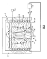
Figure 1 is a schematic illustration of an example inductive furnace with a mold disposed within the furnace. -
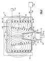
Figure 2 is a schematic illustration of the example inductive furnace with the mold partially withdrawn from the furnace. -
Figure 3 is a schematic illustration of another example inductive furnace including a plurality of openings in an example susceptor. -
Figure 4 is a schematic illustration of another example inductive furnace including a single opening in an example susceptor. -
Figure 5 is a schematic illustration of another example inductive furnace including another example susceptor. -
Figure 6 is a schematic illustration of another example inductive furnace that includes an example inductive coil with a variable configuration. - Referring to
Figure 1 , an exampleinduction furnace assembly 10 includes achamber 12 that includes anopening 14 through which amold 32 is received and withdrawn. Thechamber 12 is isolated from the external environment byinsulated walls 16. Aninductive coil 18 generates heat, indicated byarrows 50, to maintainmetal 34 within themold 32 at a desired temperature. - The example furnace assembly includes a
susceptor 22 that blocks a portion of a magnetic field (schematically shown at 52) that is generated by theinductive coil 18. Theexample susceptor 22 is a wall that surrounds thechamber 12 and is made of a graphite material. Thesusceptor 22 is fabricated from material such as graphite that blocks the penetration of themagnetic field 52 produced by theinductive coil 18. Thesusceptor 22 can also provide for the translation of energy from the magnetic field into heat energy, as indicated atarrows 50 to further maintain a temperature within themold 32. In the disclosed example,molten metal material 34 is disposed in themold 32 and supported on asupport 38. Theexample support 38 includes achill plate 40 that both supports themold 32 and includes cooling features to aid in cooling themolten material 34. - The
inductive coil 18 receives electrical energy from an electric power source schematically indicated at 44. This electrical energy is provided at a desired current level determined to provide sufficient power and energy to create the desired temperature within thechamber 12 that maintains themolten metal 34 in a molten state. - The example
inductive coil 18 comprises a plurality of electrically conductivehollow tubes 20. The plurality oftubes 20 also provide for the circulation of a fluid that is generated by apump 46 that supplies fluid from afluid source 48 to flow through thetubes 20. - In the example a directional solidification casting process is utilized where molten material is poured into the
mold 32 within thechamber 12 at a desired temperature to maintain the molten material in a molten state. Thesupport 38 is then lowered through the opening 14 out of thehot chamber 12. Themold 32 is lowered from thechamber 12 at a desired rate to cool the molten material in a controlled manner to produce desired columnar structure. The controlled cooling produces a solidification front within themolten material 34. - In many applications, the completed cast part is desired to include a specific grain structure and size. The size and structure of grains within the completed cast part provide desired material characteristics and performance, such as for example material fatigue performance. In many applications, the finer the grain size the more favorable the performance of the completed cast article. The
example furnace assembly 10 includes thesusceptor 22 with a varying thickness to block a proportionate amount of themagnetic field 52. The proportional blocking of themagnetic field 52 generates a proportional amount of magnetic stirring within themolten metal material 34. - The generated
magnetic field 52 produces currents within the molten metal material that interact with themolten metal material 34 to provide stirring and mixing to break up large grain nuclei to form smaller grain structures. In a standard induction furnace, the susceptor is sized to include a thickness that is thick enough to completely eliminate the generation of any magnetic field within the hot zone of thechamber 12. Theexample furnace 10 includes a susceptor of a varying thickness such that it can vary the strength of themagnetic field 52 depending on the position of themold 32 within thechamber 12. In this way a variable stirring can be induced within the molten material to break up the larger grain structures to form smaller and more desirable grains in a completed part. - The
example susceptor 22 includes afirst thickness 28 disposed at a portion closest to the opening 14. Thesusceptor 22 also includes asecond thickness 30 that is disposed at an end opposite the opening 14. Thesecond thickness 30 is much less then thefirst thickness 28 to allow the largest portion of themagnetic field 52 to pass into and create stirring. - The example structure of the
susceptor 22 provides for the generation of a strongest magnetic field point indicated by 54 and a weakest magnetic field point indicated at 56. Note thatpoints chamber 12 where themagnetic field 52 is at a greatest or weakest strength. - The example susceptor '22 includes the wall that is sloped at an
angle 62 between thefirst thickness 28 and thesecond thickness 30. Theexample susceptor 22 is disposed at a constant angle that provides a uniform increase in thickness in a direction towards theopening 14. The steady increase in the thickness of thesusceptor 22 in a direction towards theopening 14 provides for the steady decrease in magnetic field strength generated within thechamber 12. The decrease in the magnetic field strength towards theopening 14 produces a decrease in stirring and mixing encountered within themolten material 34. - It is desirable to decrease the magnetic stirring within the
molten material 34 as themold 32 leaves thehot chamber 12 along the solidification front to produce the desired grain structure within the completed cast part. - Referring to
Figure 2 , with continued reference toFigure 1 , theexample furnace 10 is illustrated with themold 32 partially removed from thehot chamber 12. As themold 32 is removed, asolidification front 58 is formed within themolten material 34. Mixing at the solidification front does not provide the desired fine grain structure and can disrupt any desired columnar structures, and therefore in some instances it can be desirable to reduce the amount of magnetic mixing along thesolidification front 58. Theexample induction furnace 10 reduces the magnitude of themagnetic field 52 in a direction towards the opening 14 such that as themold 32 is withdrawn from thehot chamber 12, mixing is slowly reduced until such mixing is completely stopped at a point where thesolidification front 58 is formed. - As is schematically shown, the
molten material 34 remains above thesolidification front 58 and a solidified portion of the desired castpart 60 extends downward from thesolidification front 58. Thesolidification front 58 remains substantially stationary relative to theopening 14 as themold 32 is moved downwardly and out of thechamber 12. - This process may also be utilized in concert with a
single crystal seed 36 or can use other directional solidification processes to create the desired grain structure. The amount of magnetic stirring can be tailored to provide varying amounts of mixing to induce formation of the desired grain structure in a completed part. - In operation, the
furnace 10 is brought up to a desired temperature by providing a sufficient current from the electric power source 44 to theinductive coil 18. Water supplied from thepump 46 andfluid source 48 is pumped through the plurality oftubes 20 that make up theinductive coil 18. Theheat 50 created by theinductive coil 12 and also created by a partial conversion of the magnetic field by the susceptor 22 heats thechamber 12 to a desired temperature. Once a desired temperature is reached,molten material 34 is poured into themold 32. Themold 32 defines the external shape and features of the completed cast article. In this example, aseed 36 is placed within themold 32 to further orientate the desired grain structure of the completed cast article. - The
mold 32 is placed on asupport 38. Thesupport 38 is movable in a direction axially into and out of thechamber 12.Support 38 also includes thechill plate 40 that is supplied with a coolant to maintain a desired cooling temperature to encourage cooling in a uniform manner. With the mold in thechamber 12,molten material 34 is filled within themold 32. Oncemolten material 34 is received within themold 32, themagnetic field 52 generates a mixing and stirring motion within themolten material 34. This mixing and stirring is governed by the strength of themagnetic field 52. - The shape and thickness of the
example susceptor 22 governs the strength of themagnetic field 52 by blocking a desired portion of that magnetic field generated by theinductive coil 18. In this example, thesusceptor 22 includes the increasing thickness to proportionally block a greater amount of themagnetic field 52 in a direction toward theopening 14. At the top most portion of thechamber 12, where themagnetic field 52 is at the greatest strength thesusceptor 22 is at itssmallest thickness 30. As appreciated, the susceptor thicknesses can be adapted to provide the specific magnetic field and stirring properties required to provide the desired grain structure in the completed cast article. - Referring to
Figure 3 , anotherexample furnace assembly 70 includes asusceptor 72 that includes a plurality ofopenings 74. The plurality of openings provides for a portion of themagnetic field 52 generated by theinductive coils 18 to enter thechamber 12. Accordingly, the strength of themagnetic field 52 is proportionally controlled by the number and area of the openings within thesusceptor 72. - In this example, the
susceptor 72 includes at least three zones of openings. In afirst zone 76, a large number ofopenings 74 are provided to allow the generation and strength of themagnetic field 52 to be at its greatest part. In this example, that zone is provided at the top most part of thechamber 12. - A second or
intermediate zone 78 is disposed between thefirst zone 76 and athird zone 80. Thissecond zone 78 provides an intermediate level or strength of a magnetic field to find an intermediate mixing. Thethird zone 80 blocks a greater portion of themagnetic field 52 to provide the least amount of mixing and blocks most of themagnetic field 52 at a point where themagnetic field 52 within thechamber 12 is at its weakest as is indicated by 56. Theopenings 74 are disposed through the entire thickness of thesusceptor 72 and provide for the proportional control of the magnitude of the strength of the magnetic field that is encountered within thechamber 12. - Referring to
Figure 4 , anotherexample susceptor 90 is provided for anotherfurnace assembly 88. Thesusceptor 90 of this example includes alarge opening 96. Thelarge opening 96 includes anarea 100 that decreases in a direction towards theopening 14. In this example, theopening 96 is triangular shaped having the base or largest width portion disposed at a top most portion of thechamber 12. Thesides 104 are disposed at anangle 102 that decreases to apoint 98 and smallest area 94 in a direction towards the opening 14 such that themagnetic field 52 that is blocked from entering thechamber 12 increases in a direction towards theopening 14 and withdrawal of the mold from thefurnace assembly 88. - The
example opening 96 includes thesides 104 disposed at a decreasingangle 102. Thisangle 102 is a uniform and constant to provide a proportional reduction in magnetic strength in a direction towards theopening 14. This decrease in theopening 96 provides for a change in area from alargest area 96 at the top most portion to a smaller area 94 at the bottom most portion. Decreasingarea 100 of theopening 96 provides for the controlled reduction in themagnetic field 52 that is utilized for stirring molten material within theexample furnace assembly 10. - Referring to
Figure 5 , another furnace assembly 105 is illustrated and includes theopening 96. Theopening 96 also includes a decreasingarea 100. However, theopening 96 differs from the previous example in that the side 106 is at a non-uniform angle. This non-uniform angle is utilized to tailor the strength of themagnetic field 52 as it decreases from a greatest amount of magnetic strength to a least amount of magnetic strength. As appreciated, the shape of theopening 96 can be modified to tailor the magnetic field strength and thereby the amount of mixing of the molten material. - As appreciated, the several different embodiments of the example inductive furnace assemblies all provide proportionate blocking of the
magnetic field 52 to tailor the strength of the magnetic field based on a position of the mold to further tailor mixing and stirring of the molten material of the cast part. Other areas and shapes of opening can be utilized to block portions of the magnetic field that are to generate the desired stirring that provides the desired final grain structure in the cast article. - Referring to
Figure 6 , another exampleinduction furnace assembly 110 includes aninductive coil 112 that has a variable number of turns to tailor the strength of themagnetic field 52 produced with in the chamber 124. The exampleinductive coil 112 includes portions with different numbers of windings per axial distance. The number of windings for a given current supplied by the power source 44 creates a desired magnitude of themagnetic field 52 that is produced. Increasing or decreasing the number of windings changes the strength of themagnetic field 52 that is generated. - In this example, the
susceptor 120 includes a fixedthickness 122 for the entire axial length of thechamber 12. Theinductive coil 112 includes three different zones each having different numbers of windings per axial length. The first set ofwindings 114 includes a high number of windings to produce the greatest strength of themagnetic field 52 within thechamber 12. - A second number of
turns 116 produce an intermediate magnetic field strength within thechamber 12. Athird number 118 is smaller than both the second 116 and first 114 number of turns and produces the least amount of magnetic field strength. In this example, the least amount of magnetic field strength is provided by the group ofwindings 118 disposed at a lower portion of thefurnace assembly 110. The modification of theinductive coil 112 provides the desired tailoring and proportional reduction in magnetic field strength within thechamber 12 desired to create variable mixing dependent on the axial position of the mold as it is being lowered from thefurnace assembly 110. - In another embodiment (no illustrated), the
induction coil 112 may comprise a plurality of windings or tubes wherein an inner diameter of the windings or tubes decreases in a direction towards the chamber opening. - The
induction coil 112 may comprise more than one separate coil surrounding thechamber 12. - Accordingly, the disclosed example inductive furnace assemblies provide for the generation and control of varying amounts of magnetic stirring based on a position of the mold that in turn produce the desired grain structures with the cast part.
- Although an example embodiment of this invention has been disclosed, a worker of ordinary skill in this art would recognize that certain modifications would come within the scope of this invention. For that reason, the following claims should be studied to determine the true scope and content of this invention.
Claims (15)
- An induction heated furnace assembly (10;70;88;105) for producing a directionally solidified casting, the furnace assembly comprising:a housing defining a chamber (12) including an opening (14) for receiving and withdrawing a mold (32) containing molten material for forming a cast part;an induction coil (18) for generating heat and a magnetic field within the chamber (12);a susceptor (22;72;90) for limiting a strength of the magnetic field within the chamber (12) based on a location within the chamber (12), wherein the strength of the magnetic field is different based on a position within the chamber (12) to provide different amounts of magnetic stirring of molten material within the mold (32); anda movable support (38) for moving a mold (32) into and out of the chamber (12).
- The assembly as recited in claim 1, wherein the susceptor (22;72;90) blocks a portion of the magnetic field produced by the induction coil (18) to control the strength of the magnetic field within the chamber (12).
- The assembly as recited in claim 2, wherein the portion of the magnetic field blocked by the susceptor (22;72;90) increases in a direction toward the opening (14) for receiving the mold (32).
- The assembly as recited in any preceding claim, wherein the susceptor (22) includes a wall thickness that increases in a direction toward the opening (14) in the chamber (12), wherein the amount of the magnetic field blocked by the susceptor (22) increases with an increase in wall thickness.
- The assembly as recited in claim 4, wherein the wall thickness varies uniformly from a least thickness to a greatest thickness.
- The assembly as recited in claim 4, wherein the wall thickness varies non-uniformly from a least thickness to a greatest thickness.
- The assembly as recited in any preceding claim, wherein the susceptor (72;90) includes openings that define an open space through a wall of the susceptor (72;90), an area of open space decreasing in a direction toward the opening (14) in the chamber.
- The assembly as recited in claim 7, wherein the open space comprises a plurality of openings (74) spaced apart, with the number of openings (74) decreasing in a direction toward the opening (14) in the chamber (12), or wherein the open space comprises an area (100) decreasing in a direction toward the opening (14) in the chamber (12).
- An induction heated furnace assembly (110) for producing a directionally solidified casting, the furnace assembly comprising:a housing defining a chamber (12) including an opening (14) for receiving and withdrawing a mold (32) containing molten material for forming a cast part;an induction coil (18) for generating heat and a magnetic field within the chamber (12), wherein the induction coil (18) produces a magnetic field that varies in strength based on a position within the chamber (12);a susceptor (120) for limiting a strength of the magnetic field within the chamber (120); anda movable support (38) for moving a mold (32) into and out of the chamber (12).
- The assembly as recited in claim 9, wherein the strength of the magnetic field within the chamber decreases in a direction toward the opening (14) in the chamber (12).
- The assembly as recited in claim 9 or 10, wherein the induction coil (112) includes a plurality of tubes, the plurality of tubes include a desired number of windings for a given axial length of the chamber (12), the desired number of windings decreasing in a direction toward the opening (14) in the chamber (12) to produce the magnetic field that varies in strength based on a position within the mold (32), or wherein in the induction coil (112) includes a plurality of tubes arranged in a winding about the chamber (12), the number of windings per axial length decreasing in a direction toward the opening (14) in the chamber (12), or wherein the induction coil (112) includes a plurality of tubes or windings, wherein an inner diameter of the plurality of tubes or windings decreases in a direction toward the opening (14) in the chamber (12).
- The assembly as recited in claim 9, 10 or 11, wherein the induction coil (112) comprises more than one separate coil surrounding the chamber (12).
- A method of forming a cast article in a directional solidification process comprising the steps of:generating heat within a chamber (12) at to maintain a molten material in a desired molten state;generating a magnetic field within the chamber (12) to induce stirring of the molten material within a mold (32);cooling the molten material within the mold (32) by withdrawing the mold (32) from the chamber (12);changing the magnetic field within the chamber (12) to control stirring of the molten material based on a position of the mold (32) within the chamber (12) as the mold (32) is withdrawn from the chamber (12); andremoving the mold (32) from the chamber (12) and removing the cast article from the mold (32) once the molten material solidifies.
- The method as recited in claim 13, including changing the magnetic field to reduce stirring of the molten material along a solidification front (58) to obtain a desired grain structure, for example reducing the magnetic field in a direction the same as the direction in which the mold (32) is withdrawn from the chamber (12) such that substantially no mixing occurs at the solidification front (58) of the cast article.
- The method as recited in claim 13 or 14, wherein a solidification front (58) substantially corresponds with that portion of the mold (32) and cast article disposed at the opening (14) in the chamber (12) through which the mold (32) is withdrawn.
Applications Claiming Priority (1)
| Application Number | Priority Date | Filing Date | Title |
|---|---|---|---|
| US12/406,332 US20100238967A1 (en) | 2009-03-18 | 2009-03-18 | Method of producing a fine grain casting |
Publications (2)
| Publication Number | Publication Date |
|---|---|
| EP2233228A1 true EP2233228A1 (en) | 2010-09-29 |
| EP2233228B1 EP2233228B1 (en) | 2013-10-30 |
Family
ID=42358360
Family Applications (1)
| Application Number | Title | Priority Date | Filing Date |
|---|---|---|---|
| EP10250284.6A Not-in-force EP2233228B1 (en) | 2009-03-18 | 2010-02-18 | Method of producing a fine grain casting |
Country Status (2)
| Country | Link |
|---|---|
| US (1) | US20100238967A1 (en) |
| EP (1) | EP2233228B1 (en) |
Cited By (4)
| Publication number | Priority date | Publication date | Assignee | Title |
|---|---|---|---|---|
| CN102071469A (en) * | 2011-01-13 | 2011-05-25 | 西北工业大学 | Directional solidification device with traveling-wave magnetic field generator |
| EP3482847A1 (en) * | 2017-10-30 | 2019-05-15 | United Technologies Corporation | Method for magnetic flux compensation in a directional solidification furnace utilizing an actuated secondary coil |
| EP3482849A1 (en) * | 2017-10-30 | 2019-05-15 | United Technologies Corporation | Method for magnetic flux compensation in a directional solidification furnace utilizing a stationary secondary coil |
| US10711367B2 (en) | 2017-10-30 | 2020-07-14 | Raytheon Technoiogies Corporation | Multi-layer susceptor design for magnetic flux shielding in directional solidification furnaces |
Families Citing this family (4)
| Publication number | Priority date | Publication date | Assignee | Title |
|---|---|---|---|---|
| WO2007122736A1 (en) * | 2006-04-25 | 2007-11-01 | Ebis Corporation | Casting method and apparatus |
| CN105344978A (en) * | 2015-12-16 | 2016-02-24 | 常州机电职业技术学院 | bilateral travelling wave magnetic field casting device |
| US10337121B2 (en) | 2017-10-30 | 2019-07-02 | United Technologies Corporation | Separate vessel metal shielding method for magnetic flux in directional solidification furnace |
| CN116334472B (en) * | 2023-02-03 | 2024-06-18 | 东北大学 | Preparation method of <111> oriented rare earth-iron-based magnetostrictive material |
Citations (5)
| Publication number | Priority date | Publication date | Assignee | Title |
|---|---|---|---|---|
| US3667533A (en) * | 1970-04-28 | 1972-06-06 | United Aircraft Corp | Making directionally solidified castings |
| US4108236A (en) * | 1977-04-21 | 1978-08-22 | United Technologies Corporation | Floating heat insulating baffle for directional solidification apparatus utilizing liquid coolant bath |
| US4202400A (en) | 1978-09-22 | 1980-05-13 | General Electric Company | Directional solidification furnace |
| US4409451A (en) * | 1981-08-31 | 1983-10-11 | United Technologies Corporation | Induction furnace having improved thermal profile |
| US4712604A (en) | 1986-10-14 | 1987-12-15 | The United States Of America As Represented By The Secretary Of The Air Force | Apparatus for casting directionally solidified articles |
Family Cites Families (13)
| Publication number | Priority date | Publication date | Assignee | Title |
|---|---|---|---|---|
| US3405220A (en) * | 1965-07-16 | 1968-10-08 | United Aircraft Corp | Induction electric mold heater |
| US3568752A (en) * | 1968-12-05 | 1971-03-09 | Univ Ohio State | Method for controlling the as-cast grain structure of solidified materials |
| US3981344A (en) * | 1974-08-21 | 1976-09-21 | United Technologies Corporation | Investment casting mold and process |
| FR2361181A1 (en) * | 1976-08-11 | 1978-03-10 | Onera (Off Nat Aerospatiale) | PROCESS AND APPARATUS FOR THE MOLDING OF SHAPED PARTS IN REFRACTORY COMPOSITE MATERIAL |
| US4549599A (en) * | 1978-10-19 | 1985-10-29 | United Technologies Corporation | Preventing mold and casting cracking in high rate directional solidification processes |
| US4605452A (en) * | 1981-12-14 | 1986-08-12 | United Technologies Corporation | Single crystal articles having controlled secondary crystallographic orientation |
| US4530404A (en) * | 1983-07-07 | 1985-07-23 | Aluminium Pechiney | Process for the electromagnetic casting of metals involving the use of at least one magnetic field which differs from the field of confinement |
| US4637448A (en) * | 1984-08-27 | 1987-01-20 | Westinghouse Electric Corp. | Method for production of combustion turbine blade having a single crystal portion |
| US4832112A (en) * | 1985-10-03 | 1989-05-23 | Howmet Corporation | Method of forming a fine-grained equiaxed casting |
| US4933005A (en) * | 1989-08-21 | 1990-06-12 | Mulcahy Joseph A | Magnetic control of molten metal systems |
| US5246060A (en) * | 1991-11-13 | 1993-09-21 | Aluminum Company Of America | Process for ingot casting employing a magnetic field for reducing macrosegregation and associated apparatus and ingot |
| US5451142A (en) * | 1994-03-29 | 1995-09-19 | United Technologies Corporation | Turbine engine blade having a zone of fine grains of a high strength composition at the blade root surface |
| US5577547A (en) * | 1994-04-28 | 1996-11-26 | Precision Castparts Corp. | Method of casting a metal article |
-
2009
- 2009-03-18 US US12/406,332 patent/US20100238967A1/en not_active Abandoned
-
2010
- 2010-02-18 EP EP10250284.6A patent/EP2233228B1/en not_active Not-in-force
Patent Citations (5)
| Publication number | Priority date | Publication date | Assignee | Title |
|---|---|---|---|---|
| US3667533A (en) * | 1970-04-28 | 1972-06-06 | United Aircraft Corp | Making directionally solidified castings |
| US4108236A (en) * | 1977-04-21 | 1978-08-22 | United Technologies Corporation | Floating heat insulating baffle for directional solidification apparatus utilizing liquid coolant bath |
| US4202400A (en) | 1978-09-22 | 1980-05-13 | General Electric Company | Directional solidification furnace |
| US4409451A (en) * | 1981-08-31 | 1983-10-11 | United Technologies Corporation | Induction furnace having improved thermal profile |
| US4712604A (en) | 1986-10-14 | 1987-12-15 | The United States Of America As Represented By The Secretary Of The Air Force | Apparatus for casting directionally solidified articles |
Cited By (10)
| Publication number | Priority date | Publication date | Assignee | Title |
|---|---|---|---|---|
| CN102071469A (en) * | 2011-01-13 | 2011-05-25 | 西北工业大学 | Directional solidification device with traveling-wave magnetic field generator |
| CN102071469B (en) * | 2011-01-13 | 2013-02-06 | 西北工业大学 | Directional solidification device with traveling-wave magnetic field generator |
| EP3482847A1 (en) * | 2017-10-30 | 2019-05-15 | United Technologies Corporation | Method for magnetic flux compensation in a directional solidification furnace utilizing an actuated secondary coil |
| EP3482849A1 (en) * | 2017-10-30 | 2019-05-15 | United Technologies Corporation | Method for magnetic flux compensation in a directional solidification furnace utilizing a stationary secondary coil |
| US10589351B2 (en) | 2017-10-30 | 2020-03-17 | United Technologies Corporation | Method for magnetic flux compensation in a directional solidification furnace utilizing an actuated secondary coil |
| US10711367B2 (en) | 2017-10-30 | 2020-07-14 | Raytheon Technoiogies Corporation | Multi-layer susceptor design for magnetic flux shielding in directional solidification furnaces |
| US10760179B2 (en) | 2017-10-30 | 2020-09-01 | Raytheon Technologies Corporation | Method for magnetic flux compensation in a directional solidification furnace utilizing a stationary secondary coil |
| US10907269B2 (en) | 2017-10-30 | 2021-02-02 | Raytheon Technologies Corporation | Multi-layer susceptor design for magnetic flux shielding in directional solidification furnaces |
| US10906096B2 (en) | 2017-10-30 | 2021-02-02 | Raytheon Technologies Corporation | Method for magnetic flux compensation in a directional solidification furnace utilizing an actuated secondary coil |
| US10907270B2 (en) | 2017-10-30 | 2021-02-02 | Raytheon Technologies Corporation | Method for magnetic flux compensation in a directional solidification furnace utilizing a stationary secondary coil |
Also Published As
| Publication number | Publication date |
|---|---|
| US20100238967A1 (en) | 2010-09-23 |
| EP2233228B1 (en) | 2013-10-30 |
Similar Documents
| Publication | Publication Date | Title |
|---|---|---|
| EP2233228B1 (en) | Method of producing a fine grain casting | |
| JPH02287091A (en) | Induction furnace | |
| US7848383B2 (en) | Cold crucible induction furnace with eddy current damping | |
| US9476645B2 (en) | Open bottom electric induction cold crucible for use in electromagnetic casting of ingots | |
| EP3482847B1 (en) | Method for magnetic flux compensation in a directional solidification furnace utilizing an actuated secondary coil | |
| EP3492197A1 (en) | Separate vessel metal shielding method for magnetic flux in directional solidification furnace | |
| CN102021643A (en) | Method and device for directionally solidifying liquid-solid interface based on alternating magnetic field modulation | |
| EP3482848B1 (en) | Multi-layer susceptor design for magnetic flux shielding in directional solidification furnaces | |
| RU2751614C1 (en) | Compact induction coil assembly for vacuum arc remelting system | |
| JP2018094628A (en) | Casting method of active metal | |
| WO2009058894A2 (en) | Electric induction heating and melting of an electrically conductive material in a containment vessel | |
| US5708257A (en) | Heating device for transfer of liquid metal and process for manufacturing the device | |
| EP3482849B1 (en) | Method for magnetic flux compensation in a directional solidification furnace utilizing a stationary secondary coil | |
| JP4640349B2 (en) | Continuous casting apparatus and casting method in continuous casting apparatus | |
| JP2010017749A (en) | Melting furnace, continuous casting apparatus, and casting method for continuous casting apparatus | |
| RU2735329C1 (en) | Method of levitation melting using annular element | |
| SU508332A1 (en) | Device for continuous casting of metal | |
| US9988740B1 (en) | Shaped induction field crystal printer | |
| KR102910305B1 (en) | Controlled casting of in-mold large-scale ingots using inductive variable power and variable frequency. | |
| RU2790366C1 (en) | Induction device for heating flat metal workpieces in a state of levitation | |
| CN114303035B (en) | Induction furnace including additional resonant circuit | |
| JP2012228722A (en) | Melting furnace for smelting metal | |
| JP3613808B2 (en) | Processing method of conductive metal | |
| WO2018110370A1 (en) | Casting method for active metal | |
| CN110944769A (en) | Electromagnetically modified metal casting method |
Legal Events
| Date | Code | Title | Description |
|---|---|---|---|
| PUAI | Public reference made under article 153(3) epc to a published international application that has entered the european phase |
Free format text: ORIGINAL CODE: 0009012 |
|
| AK | Designated contracting states |
Kind code of ref document: A1 Designated state(s): AT BE BG CH CY CZ DE DK EE ES FI FR GB GR HR HU IE IS IT LI LT LU LV MC MK MT NL NO PL PT RO SE SI SK SM TR |
|
| AX | Request for extension of the european patent |
Extension state: AL BA RS |
|
| 17P | Request for examination filed |
Effective date: 20110329 |
|
| 17Q | First examination report despatched |
Effective date: 20110614 |
|
| GRAP | Despatch of communication of intention to grant a patent |
Free format text: ORIGINAL CODE: EPIDOSNIGR1 |
|
| GRAP | Despatch of communication of intention to grant a patent |
Free format text: ORIGINAL CODE: EPIDOSNIGR1 |
|
| INTG | Intention to grant announced |
Effective date: 20130724 |
|
| GRAS | Grant fee paid |
Free format text: ORIGINAL CODE: EPIDOSNIGR3 |
|
| GRAA | (expected) grant |
Free format text: ORIGINAL CODE: 0009210 |
|
| AK | Designated contracting states |
Kind code of ref document: B1 Designated state(s): AT BE BG CH CY CZ DE DK EE ES FI FR GB GR HR HU IE IS IT LI LT LU LV MC MK MT NL NO PL PT RO SE SI SK SM TR |
|
| REG | Reference to a national code |
Ref country code: GB Ref legal event code: FG4D |
|
| REG | Reference to a national code |
Ref country code: CH Ref legal event code: EP |
|
| REG | Reference to a national code |
Ref country code: AT Ref legal event code: REF Ref document number: 638320 Country of ref document: AT Kind code of ref document: T Effective date: 20131115 |
|
| REG | Reference to a national code |
Ref country code: IE Ref legal event code: FG4D |
|
| REG | Reference to a national code |
Ref country code: DE Ref legal event code: R096 Ref document number: 602010011303 Country of ref document: DE Effective date: 20131224 |
|
| REG | Reference to a national code |
Ref country code: NL Ref legal event code: VDEP Effective date: 20131030 |
|
| REG | Reference to a national code |
Ref country code: AT Ref legal event code: MK05 Ref document number: 638320 Country of ref document: AT Kind code of ref document: T Effective date: 20131030 |
|
| REG | Reference to a national code |
Ref country code: LT Ref legal event code: MG4D |
|
| PG25 | Lapsed in a contracting state [announced via postgrant information from national office to epo] |
Ref country code: HR Free format text: LAPSE BECAUSE OF FAILURE TO SUBMIT A TRANSLATION OF THE DESCRIPTION OR TO PAY THE FEE WITHIN THE PRESCRIBED TIME-LIMIT Effective date: 20131030 Ref country code: FI Free format text: LAPSE BECAUSE OF FAILURE TO SUBMIT A TRANSLATION OF THE DESCRIPTION OR TO PAY THE FEE WITHIN THE PRESCRIBED TIME-LIMIT Effective date: 20131030 Ref country code: LT Free format text: LAPSE BECAUSE OF FAILURE TO SUBMIT A TRANSLATION OF THE DESCRIPTION OR TO PAY THE FEE WITHIN THE PRESCRIBED TIME-LIMIT Effective date: 20131030 Ref country code: BE Free format text: LAPSE BECAUSE OF FAILURE TO SUBMIT A TRANSLATION OF THE DESCRIPTION OR TO PAY THE FEE WITHIN THE PRESCRIBED TIME-LIMIT Effective date: 20131030 Ref country code: NL Free format text: LAPSE BECAUSE OF FAILURE TO SUBMIT A TRANSLATION OF THE DESCRIPTION OR TO PAY THE FEE WITHIN THE PRESCRIBED TIME-LIMIT Effective date: 20131030 Ref country code: IS Free format text: LAPSE BECAUSE OF FAILURE TO SUBMIT A TRANSLATION OF THE DESCRIPTION OR TO PAY THE FEE WITHIN THE PRESCRIBED TIME-LIMIT Effective date: 20140228 Ref country code: NO Free format text: LAPSE BECAUSE OF FAILURE TO SUBMIT A TRANSLATION OF THE DESCRIPTION OR TO PAY THE FEE WITHIN THE PRESCRIBED TIME-LIMIT Effective date: 20140130 Ref country code: SE Free format text: LAPSE BECAUSE OF FAILURE TO SUBMIT A TRANSLATION OF THE DESCRIPTION OR TO PAY THE FEE WITHIN THE PRESCRIBED TIME-LIMIT Effective date: 20131030 |
|
| PG25 | Lapsed in a contracting state [announced via postgrant information from national office to epo] |
Ref country code: CY Free format text: LAPSE BECAUSE OF FAILURE TO SUBMIT A TRANSLATION OF THE DESCRIPTION OR TO PAY THE FEE WITHIN THE PRESCRIBED TIME-LIMIT Effective date: 20131030 Ref country code: AT Free format text: LAPSE BECAUSE OF FAILURE TO SUBMIT A TRANSLATION OF THE DESCRIPTION OR TO PAY THE FEE WITHIN THE PRESCRIBED TIME-LIMIT Effective date: 20131030 Ref country code: LV Free format text: LAPSE BECAUSE OF FAILURE TO SUBMIT A TRANSLATION OF THE DESCRIPTION OR TO PAY THE FEE WITHIN THE PRESCRIBED TIME-LIMIT Effective date: 20131030 Ref country code: ES Free format text: LAPSE BECAUSE OF FAILURE TO SUBMIT A TRANSLATION OF THE DESCRIPTION OR TO PAY THE FEE WITHIN THE PRESCRIBED TIME-LIMIT Effective date: 20131030 |
|
| PG25 | Lapsed in a contracting state [announced via postgrant information from national office to epo] |
Ref country code: PT Free format text: LAPSE BECAUSE OF FAILURE TO SUBMIT A TRANSLATION OF THE DESCRIPTION OR TO PAY THE FEE WITHIN THE PRESCRIBED TIME-LIMIT Effective date: 20140228 |
|
| PG25 | Lapsed in a contracting state [announced via postgrant information from national office to epo] |
Ref country code: EE Free format text: LAPSE BECAUSE OF FAILURE TO SUBMIT A TRANSLATION OF THE DESCRIPTION OR TO PAY THE FEE WITHIN THE PRESCRIBED TIME-LIMIT Effective date: 20131030 |
|
| REG | Reference to a national code |
Ref country code: DE Ref legal event code: R097 Ref document number: 602010011303 Country of ref document: DE |
|
| PG25 | Lapsed in a contracting state [announced via postgrant information from national office to epo] |
Ref country code: IT Free format text: LAPSE BECAUSE OF FAILURE TO SUBMIT A TRANSLATION OF THE DESCRIPTION OR TO PAY THE FEE WITHIN THE PRESCRIBED TIME-LIMIT Effective date: 20131030 Ref country code: CZ Free format text: LAPSE BECAUSE OF FAILURE TO SUBMIT A TRANSLATION OF THE DESCRIPTION OR TO PAY THE FEE WITHIN THE PRESCRIBED TIME-LIMIT Effective date: 20131030 Ref country code: RO Free format text: LAPSE BECAUSE OF FAILURE TO SUBMIT A TRANSLATION OF THE DESCRIPTION OR TO PAY THE FEE WITHIN THE PRESCRIBED TIME-LIMIT Effective date: 20131030 Ref country code: SK Free format text: LAPSE BECAUSE OF FAILURE TO SUBMIT A TRANSLATION OF THE DESCRIPTION OR TO PAY THE FEE WITHIN THE PRESCRIBED TIME-LIMIT Effective date: 20131030 Ref country code: PL Free format text: LAPSE BECAUSE OF FAILURE TO SUBMIT A TRANSLATION OF THE DESCRIPTION OR TO PAY THE FEE WITHIN THE PRESCRIBED TIME-LIMIT Effective date: 20131030 |
|
| PLBE | No opposition filed within time limit |
Free format text: ORIGINAL CODE: 0009261 |
|
| STAA | Information on the status of an ep patent application or granted ep patent |
Free format text: STATUS: NO OPPOSITION FILED WITHIN TIME LIMIT |
|
| PG25 | Lapsed in a contracting state [announced via postgrant information from national office to epo] |
Ref country code: MC Free format text: LAPSE BECAUSE OF FAILURE TO SUBMIT A TRANSLATION OF THE DESCRIPTION OR TO PAY THE FEE WITHIN THE PRESCRIBED TIME-LIMIT Effective date: 20131030 Ref country code: LU Free format text: LAPSE BECAUSE OF FAILURE TO SUBMIT A TRANSLATION OF THE DESCRIPTION OR TO PAY THE FEE WITHIN THE PRESCRIBED TIME-LIMIT Effective date: 20140218 Ref country code: DK Free format text: LAPSE BECAUSE OF FAILURE TO SUBMIT A TRANSLATION OF THE DESCRIPTION OR TO PAY THE FEE WITHIN THE PRESCRIBED TIME-LIMIT Effective date: 20131030 |
|
| REG | Reference to a national code |
Ref country code: CH Ref legal event code: PL |
|
| 26N | No opposition filed |
Effective date: 20140731 |
|
| PG25 | Lapsed in a contracting state [announced via postgrant information from national office to epo] |
Ref country code: CH Free format text: LAPSE BECAUSE OF NON-PAYMENT OF DUE FEES Effective date: 20140228 Ref country code: LI Free format text: LAPSE BECAUSE OF NON-PAYMENT OF DUE FEES Effective date: 20140228 |
|
| REG | Reference to a national code |
Ref country code: DE Ref legal event code: R097 Ref document number: 602010011303 Country of ref document: DE Effective date: 20140731 |
|
| REG | Reference to a national code |
Ref country code: FR Ref legal event code: ST Effective date: 20141031 |
|
| REG | Reference to a national code |
Ref country code: IE Ref legal event code: MM4A |
|
| PG25 | Lapsed in a contracting state [announced via postgrant information from national office to epo] |
Ref country code: FR Free format text: LAPSE BECAUSE OF NON-PAYMENT OF DUE FEES Effective date: 20140228 Ref country code: IE Free format text: LAPSE BECAUSE OF NON-PAYMENT OF DUE FEES Effective date: 20140218 |
|
| PG25 | Lapsed in a contracting state [announced via postgrant information from national office to epo] |
Ref country code: SI Free format text: LAPSE BECAUSE OF FAILURE TO SUBMIT A TRANSLATION OF THE DESCRIPTION OR TO PAY THE FEE WITHIN THE PRESCRIBED TIME-LIMIT Effective date: 20131030 |
|
| PG25 | Lapsed in a contracting state [announced via postgrant information from national office to epo] |
Ref country code: MT Free format text: LAPSE BECAUSE OF FAILURE TO SUBMIT A TRANSLATION OF THE DESCRIPTION OR TO PAY THE FEE WITHIN THE PRESCRIBED TIME-LIMIT Effective date: 20131030 |
|
| PG25 | Lapsed in a contracting state [announced via postgrant information from national office to epo] |
Ref country code: SM Free format text: LAPSE BECAUSE OF FAILURE TO SUBMIT A TRANSLATION OF THE DESCRIPTION OR TO PAY THE FEE WITHIN THE PRESCRIBED TIME-LIMIT Effective date: 20131030 |
|
| PG25 | Lapsed in a contracting state [announced via postgrant information from national office to epo] |
Ref country code: GR Free format text: LAPSE BECAUSE OF FAILURE TO SUBMIT A TRANSLATION OF THE DESCRIPTION OR TO PAY THE FEE WITHIN THE PRESCRIBED TIME-LIMIT Effective date: 20140131 Ref country code: BG Free format text: LAPSE BECAUSE OF FAILURE TO SUBMIT A TRANSLATION OF THE DESCRIPTION OR TO PAY THE FEE WITHIN THE PRESCRIBED TIME-LIMIT Effective date: 20131030 |
|
| PG25 | Lapsed in a contracting state [announced via postgrant information from national office to epo] |
Ref country code: TR Free format text: LAPSE BECAUSE OF FAILURE TO SUBMIT A TRANSLATION OF THE DESCRIPTION OR TO PAY THE FEE WITHIN THE PRESCRIBED TIME-LIMIT Effective date: 20131030 Ref country code: HU Free format text: LAPSE BECAUSE OF FAILURE TO SUBMIT A TRANSLATION OF THE DESCRIPTION OR TO PAY THE FEE WITHIN THE PRESCRIBED TIME-LIMIT; INVALID AB INITIO Effective date: 20100218 |
|
| REG | Reference to a national code |
Ref country code: DE Ref legal event code: R082 Ref document number: 602010011303 Country of ref document: DE Representative=s name: SCHMITT-NILSON SCHRAUD WAIBEL WOHLFROM PATENTA, DE |
|
| REG | Reference to a national code |
Ref country code: DE Ref legal event code: R082 Ref document number: 602010011303 Country of ref document: DE Representative=s name: SCHMITT-NILSON SCHRAUD WAIBEL WOHLFROM PATENTA, DE Ref country code: DE Ref legal event code: R081 Ref document number: 602010011303 Country of ref document: DE Owner name: UNITED TECHNOLOGIES CORP. (N.D.GES.D. STAATES , US Free format text: FORMER OWNER: UNITED TECHNOLOGIES CORPORATION, HARTFORD, CONN., US |
|
| PG25 | Lapsed in a contracting state [announced via postgrant information from national office to epo] |
Ref country code: MK Free format text: LAPSE BECAUSE OF FAILURE TO SUBMIT A TRANSLATION OF THE DESCRIPTION OR TO PAY THE FEE WITHIN THE PRESCRIBED TIME-LIMIT Effective date: 20131030 |
|
| REG | Reference to a national code |
Ref country code: DE Ref legal event code: R081 Ref document number: 602010011303 Country of ref document: DE Owner name: RAYTHEON TECHNOLOGIES CORPORATION (N.D.GES.D.S, US Free format text: FORMER OWNER: UNITED TECHNOLOGIES CORP. (N.D.GES.D. STAATES DELAWARE), FARMINGTON, CONN., US |
|
| PGFP | Annual fee paid to national office [announced via postgrant information from national office to epo] |
Ref country code: GB Payment date: 20230121 Year of fee payment: 14 Ref country code: DE Payment date: 20230119 Year of fee payment: 14 |
|
| P01 | Opt-out of the competence of the unified patent court (upc) registered |
Effective date: 20230519 |
|
| REG | Reference to a national code |
Ref country code: DE Ref legal event code: R119 Ref document number: 602010011303 Country of ref document: DE |
|
| GBPC | Gb: european patent ceased through non-payment of renewal fee |
Effective date: 20240218 |
|
| PG25 | Lapsed in a contracting state [announced via postgrant information from national office to epo] |
Ref country code: DE Free format text: LAPSE BECAUSE OF NON-PAYMENT OF DUE FEES Effective date: 20240903 |
|
| PG25 | Lapsed in a contracting state [announced via postgrant information from national office to epo] |
Ref country code: GB Free format text: LAPSE BECAUSE OF NON-PAYMENT OF DUE FEES Effective date: 20240218 |
|
| PG25 | Lapsed in a contracting state [announced via postgrant information from national office to epo] |
Ref country code: GB Free format text: LAPSE BECAUSE OF NON-PAYMENT OF DUE FEES Effective date: 20240218 Ref country code: DE Free format text: LAPSE BECAUSE OF NON-PAYMENT OF DUE FEES Effective date: 20240903 |