EP2232342B1 - Turbulenzaufbereitungsvorrichtung für transitzeit-ultraschallströmungsmesser und verfahren - Google Patents
Turbulenzaufbereitungsvorrichtung für transitzeit-ultraschallströmungsmesser und verfahren Download PDFInfo
- Publication number
- EP2232342B1 EP2232342B1 EP08862021.6A EP08862021A EP2232342B1 EP 2232342 B1 EP2232342 B1 EP 2232342B1 EP 08862021 A EP08862021 A EP 08862021A EP 2232342 B1 EP2232342 B1 EP 2232342B1
- Authority
- EP
- European Patent Office
- Prior art keywords
- conditioner
- turbulence
- pipe
- pitch
- meter
- Prior art date
- Legal status (The legal status is an assumption and is not a legal conclusion. Google has not performed a legal analysis and makes no representation as to the accuracy of the status listed.)
- Active
Links
Images


Classifications
-
- G—PHYSICS
- G01—MEASURING; TESTING
- G01F—MEASURING VOLUME, VOLUME FLOW, MASS FLOW OR LIQUID LEVEL; METERING BY VOLUME
- G01F1/00—Measuring the volume flow or mass flow of fluid or fluent solid material wherein the fluid passes through a meter in a continuous flow
- G01F1/66—Measuring the volume flow or mass flow of fluid or fluent solid material wherein the fluid passes through a meter in a continuous flow by measuring frequency, phase shift or propagation time of electromagnetic or other waves, e.g. using ultrasonic flowmeters
- G01F1/667—Arrangements of transducers for ultrasonic flowmeters; Circuits for operating ultrasonic flowmeters
-
- G—PHYSICS
- G01—MEASURING; TESTING
- G01F—MEASURING VOLUME, VOLUME FLOW, MASS FLOW OR LIQUID LEVEL; METERING BY VOLUME
- G01F1/00—Measuring the volume flow or mass flow of fluid or fluent solid material wherein the fluid passes through a meter in a continuous flow
- G01F1/66—Measuring the volume flow or mass flow of fluid or fluent solid material wherein the fluid passes through a meter in a continuous flow by measuring frequency, phase shift or propagation time of electromagnetic or other waves, e.g. using ultrasonic flowmeters
- G01F1/662—Constructional details
-
- G—PHYSICS
- G01—MEASURING; TESTING
- G01F—MEASURING VOLUME, VOLUME FLOW, MASS FLOW OR LIQUID LEVEL; METERING BY VOLUME
- G01F15/00—Details of, or accessories for, apparatus of groups G01F1/00 - G01F13/00 insofar as such details or appliances are not adapted to particular types of such apparatus
-
- Y—GENERAL TAGGING OF NEW TECHNOLOGICAL DEVELOPMENTS; GENERAL TAGGING OF CROSS-SECTIONAL TECHNOLOGIES SPANNING OVER SEVERAL SECTIONS OF THE IPC; TECHNICAL SUBJECTS COVERED BY FORMER USPC CROSS-REFERENCE ART COLLECTIONS [XRACs] AND DIGESTS
- Y10—TECHNICAL SUBJECTS COVERED BY FORMER USPC
- Y10T—TECHNICAL SUBJECTS COVERED BY FORMER US CLASSIFICATION
- Y10T29/00—Metal working
- Y10T29/49—Method of mechanical manufacture
Definitions
- the present invention is related to the altering of the structure of turbulence in a pipe such that the turbulent variations of the fluid velocity, as measured by a transit time ultrasonic flow meter downstream of a turbulence conditioner, are much reduced.
- references to the "present invention” or “invention” relate to exemplary embodiments and not necessarily to every embodiment encompassed by the appended claims.
- the reduction in turbulent velocity variations facilitates the "proving" of the ultrasonic meter-confinning its calibration against a standard-making it possible to confirm this calibration with significantly fewer runs of the prover than is possible with the same ultrasonic meter and the same prover operating without the turbulence conditioner.
- Transit time ultrasonic flowmeters have exhibited excellent repeatability and absolute accuracy in many flow measurement applications.
- characteristics inherent in the nature of their measurements present difficulties when these meters are applied to custody transfer measurements of petroleum products.
- a custody transfer takes place when ownership of a batch of a particular product changes. On a small scale, such a transfer takes place at the pump in a gas station, between the owner of the gas station and his customer.
- Provers are usually devices of fixed and precisely established volume.
- the time required to deliver the volume of product defined by the prover is accurately defined by the transit of a ball or piston, pushed by the product, from one end of the prover to the other.
- High speed diverter valves initiate the prover run and bypass the prover when the ball reaches the end of its travel.
- Position switches at the beginning and end of the prover synchronize the proving operation with the operation of the custody transfer meter the meter to be used to measure the amount of product delivered to a specific customer.
- the volumetric output measured by the custody transfer meter (in traditional practice, a turbine or positive displacement meter) during the proving run is compared to the volume of the prover and a meter factor (i.e., a calibration correction) is established.
- a transit time ultrasonic flow meter does not measure volumetric flow rate continuously, but instead infers it from multiple samples of fluid velocity.
- the volumetric flow rate is determined from periodic measurements of the axial fluid velocity as projected onto one or more acoustic paths-paths along which the transit times of pulses of ultrasound are measured. The path velocity measurements are combined according to rules appropriate to their number and location in the pipe. Many meters employ parallel chordal paths arranged in accordance with a specific method of numerical integration.
- the period over which an ultrasonic transit time meter collects a single set of velocity measurements is determined by the path transit times, the number of paths, and the data processing capabilities of the meter itself.
- the flow samples will typically be collected over periods ranging from 5 to 100 milliseconds, resulting in sample frequencies between 10 Hz and 200 Hz. These figures may differ from one ultrasonic meter design to another.
- a transit time ultrasonic meter responds to flow phenomena like turbulence differently than other meters commonly used for custody transfer in the petroleum industry. More specifically, the individual flow measurements of transit time ultrasonic meters will be affected by the small scale random (i.e., turbulent) variations in local fluid velocity. These variations are both temporal and spatial, and an ultrasonic instrument must make multiple measurements to determine the true average flow rate to reduce the random error contributions due to turbulence to acceptable levels. Turbine meters and positive displacement meters, on the other hand, respond to the flow field in the pipe as a whole; integration of the fluid velocity in space and time is inherent in the nature of their responses. On the other side of the ledger, transit time ultrasonic meters are not encumbered by physical limitations like bypass leakage and friction, and may therefore provide measurement capability over a wider range of velocity and viscosity conditions.
- flow meters are designed to produce pulses per unit volume of fluid that passes through them (for example, 1000 pulses/barrel).
- V is the volume of the standard the prover between the two position switches embedded in its walls.
- NP is the number of pulses produced by the meter during the period which begins when the upstream switch is actuated (time T1) and ends when the downstream switch is actuated (time T2).
- Ultrasonic meters determine a flow rate Q in volume units per second from individual measurements of fluid velocity along one or more acoustic paths. They therefore must generate pulses by means of a frequency converter that produces pulses at a rate k exactly proportional to the volumetric flow rate.
- dQ(N) is one standard deviation of the mean of the N flow samples collected during the prove, or ⁇ mean (N).
- ⁇ mean (N) S / N 1 / 2
- S is the standard deviation of the population of flow samples the quantitative characterization of the random variability, produced by the turbulence, in the individual flow measurements of the ultrasonic meter, from one flow sample to the next.
- Turbulence such as normally encountered in petroleum product pipelines, adversely affects the repeatability of the meter factors for transit time ultrasonic flowmeters, as measured in short duration prover runs. Unless something is done to alter the character of the turbulence, it appears that ultrasonic flowmeter meter factors measured with conventional provers will not achieve repeatability figures meeting petroleum industry expectations.
- U.S. Patent No. 6,647,806 is based on the hypothesis put forward by Dryden. ( Hugh L. Dryden and G.B. Schubauer, The Use of Damping Screens for the Reduction of Wind Tunnel Turbulence, Journal of Aeronautical Science, April 1947 .) He tied the reduction in turbulence produced by a series of one or more fine mesh screens in cascade to the production of eddies of very small diameters whose energy was dissipated as heat in a settling chamber downstream of the screen(s). Because screens are structurally impractical for resisting the hydraulic forces produced by liquid flow, the means proposed by the patent endeavored to produce the same effect with relatively small holes in plates.
- the method for reducing the effects of turbulence employed by the turbulence conditioners of this invention does not rely on the elimination of turbulence through the dissipation of very small eddies. Rather, the reduction in the random deviations of flow samples is brought about reducing the eddy sizes such that they are effectively averaged within the acoustic beams of the ultrasonic meter.
- the reduction in eddy sizes produced by the turbulence conditioners of this invention also leads to an increase in the frequencies of the random variations in fluid velocity produced by the turbulence.
- the frequency increases also lead to improved proving performance, by making a limited sample of N velocity measurements collected during a proving run more representative of the entire population of velocity variations.
- US 6748811 describes an ultrasonic flow meter including a measurement flow path through which a fluid to be measured flows, ultrasonic transducers provided respectively on an upstream side and a downstream side with respect to each other along the measurement flow path, and upstream and downstream aperture holes for exposing the ultrasonic transducers to the measurement flow path.
- the apparatus further includes a first influent suppressor provided in a vicinity of at least the downstream aperture hole for reducing inflow of the fluid to be measured into the aperture hole, a second influent suppressor provided on an upstream side of the measurement flow path with respect to the aperture holes for reducing the inflow of the fluid to be measured into the aperture holes and a measurement control section for measuring a propagation time of an ultrasonic wave between the ultrasonic transducers.
- a calculation section calculates a flow rate based on a signal from the measurement control section.
- the present invention resides in an apparatus for determining fluid flow in a pipe as defined in claims 1 to 7, a method for determining fluid flow in a pipe as defined in claims 8 and 9 and in a method for producing a turbulence conditioner for use with an ultrasonic flow meter in a pipe as defined in claims 10 and 11 of the appended claims.
- the alteration of the turbulence by the apparatus is such that a meter calibration meeting very narrow accuracy requirements can be determined in a few runs of a prover (a volumetric standard), a capability not otherwise achievable.
- a prover a volumetric standard
- Several turbulence conditioner configurations that will produce the necessary alteration to the turbulence are described.
- a second arrangement of the apparatus is also described. It draws on a configuration employing a reducing nozzle downstream of the turbulence conditioner but upstream of the meter.
- an exemplary apparatus 10 for determining fluid flow in a pipe 12 comprises an ultrasonic flowmeter 14 which communicates with the interior of the pipe 12 through at least one pair of apertures 18, where each aperture 18 of the one pair of apertures 18 has an effective diameter.
- the apparatus 10 comprises a turbulence conditioner 16 disposed in the pipe 12 having openings 22 where the pitch between openings 22 is a function of the effective diameter of the aperture 18.
- the conditioner 16 has walls 20 between the openings 22 whose thickness can be a function of the pitch.
- the conditioner 16 has a length which can be a function of the pitch.
- the meter 14 can be disposed up to 3 internal pipe 12 diameters downstream of the conditioner 16.
- the pitch can be less than the effective diameter of the aperture 18.
- the walls 20 can have a thickness between 1/4 and 1/10 of the pitch.
- the length can be 5 to 20 times the pitch.
- the pitch can be a function of the meter's 14 diameter.
- the pitch can be a function of the meter's 14 maximum velocity.
- the pitch can be a function of the meter's 14 sampling rate.
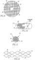
- the holes can have a cross-section that is two or more sided.
- Figure 12 shows holes that are two sided.
- the holes can have a circular cross-section, as shown in figures 4a and 4b .
- a filter 26 can be disposed in the pipe 12 upstream from the conditioner 16.
- a nozzle 24 can be disposed in the pipe 12 upstream of the flowmeter 14 and downstream of the conditioner 16.
- the meter 14 and the conditioner 16 can satisfy proving requirements for maximum and minimum flow velocities for which the meter is designed.
- the conditioner 16 and the meter 14 can satisfy a proving requirement of +/- 0.027% uncertainty in five proving runs.
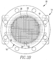
- the present invention pertains to a turbulence conditioner 16 for a pipe 12, as shown in figures 1A, 1B , 2 , 3A , 3B , 3C , 4A , 4B and 4C .
- the conditioner 16 has openings 22 and a pitch.
- the conditioner 16 has walls 20 between the openings 22 whose thickness is a function of the pitch.
- the conditioner 16 has a length which is a function of the pitch.
- the present invention pertains to a method for determining fluid flow in a pipe 12.
- the method comprises the steps of flowing fluid through a turbulence conditioner 16 disposed in the pipe 12 having openings 22 where the pitch between openings 22, is made a function of an effective diameter of an aperture 18 of an ultrasonic flowmeter 14 which communicates with the interior of the pipe 12 through the aperture 18.
- the flowing fluid through a turbulence conditioner 16 step can include the step of flowing the fluid through the turbulence conditioner 16 wherein the conditioner 16 has walls 20 between the openings 22 whose thickness is made a function of the pitch.
- the flowing fluid through a turbulence conditioner 16 step can include the step of flowing the fluid through the turbulence conditioner 16 wherein the conditioner 16 has a length which is made a function of the pitch.
- the flowing fluid through a turbulence conditioner 16 step can include the step of flowing the fluid through the turbulence conditioner 16 disposed up to 3 internal pipe 12 diameters upstream of the conditioner 16.
- the flowing fluid through a turbulence conditioner 16 step can include the step of flowing the fluid through the turbulence conditioner 16 wherein the pitch is less than the effective diameter of the aperture 18.
- the flowing fluid through a turbulence conditioner 16 step can include the step of flowing the fluid through the turbulence conditioner 16 wherein the walls 20 have a thickness between 1/4 to 1/10 of the pitch.
- the flowing fluid through a turbulence conditioner 16 step can include the step of flowing the fluid through the turbulence conditioner 16 wherein the length of the conditioner 16 is 5 to 20 times the pitch.
- the flowing fluid through a turbulence conditioner 16 step can include the step of flowing the fluid through the turbulence conditioner 16 wherein the holes have a cross-section that is two or more sided.
- the flowing fluid through a turbulence conditioner 16 step includes the step of flowing the fluid through the turbulence conditioner 16 wherein the holes have a circular cross-section.
- the flowing fluid through a turbulence conditioner 16 step can include the step of flowing the fluid through a filter 26 disposed in the pipe 12 upstream from the conditioner 16.
- the flowing fluid through a turbulence conditioner 16 step can include the step of flowing the fluid through a nozzle 24 disposed in the pipe 12 upstream of the flowmeter 14 and downstream of the conditioner 16.
- the measuring step can include the step of measuring the flow with the meter 14 which meets a proving requirement.
- the measuring step can include the step of measuring the flow with the meter 14 which meets the proving requirement of +/- 0.027% uncertainty in five proving runs.
- the present invention pertains to a method for producing a turbulence conditioner 16 for use with an ultrasonic flowmeter 14 in a pipe 12.
- the method comprises the steps of identifying an effective diameter of an aperture in the pipe 12 through which the flowmeter 14 communicates with the interior of the pipe 12. There is the step of determining a pitch between holes in the conditioner 16 as a function of the effective diameter.
- the step of determining a thickness of walls between the openings as a function of the pitch can be the step of determining a length of the conditioner 16 as a function of the pitch.
- the step of building the conditioner 16 having the pitch, wall thickness and length determined in the determining steps could include fabricating the center portion 35 having the holes 22, cutting it to length and diameter to meet the design parameters determined for the pitch, wall thickness and length, and attaching a flange 37 to the center portion 35 so it can be seated in the pipe 12.
- the present invention pertains to an apparatus 10 for determining fluid flow in a pipe 12, comprising a turbulence-altering turbulence conditioner 16 and an ultrasonic transit time flowmeter 14, both placed in the pipe 12.
- the arrangement facilitates the "proving" of the ultrasonic meter 14 in a number of prover runs comparable to, or better than the number required by meters of competing technologies (turbine meters and positive displacement meters) an accomplishment not possible with conventional arrangements of ultrasonic meters 14.
- turbulence conditioner 16 Several alternative configurations for the turbulence conditioner 16 are described.
- the turbulence conditioners 16 can also be applied to an alternative arrangement of the enclosing piping and ultrasonic meter 14 which has been described in the prior art, and in which a nozzle 24 type reducer is employed upstream of the ultrasonic meter 14 but downstream of the turbulence conditioner 16, with proving results better than previously achieved with this arrangement.
- Figures 1A, 1B and 2 show one of the several alternative turbulence conditioners 16 employed by this invention with a chordal ultrasonic meter 14 downstream, as prescribed by this invention.
- the configuration referred to as a "honeycomb" having six sides, has been tested to demonstrate the capabilities of this invention. Results will be described in later paragraphs.
- the key dimensional requirements of this exemplary embodiment of the invention are as follows:
- Figures 3A , 3B , 3C , 4A , 4B and 4C show alternative configurations for turbulence conditioners 16 meeting the requirements prescribed above.
- the axial length of the conditioner 16 provides stiffness which reduces axial deflections and stresses to very small values provided the egg-crate of Figures 3A , 3B , and 3C and the tube bundle of Figures 4A , 4B , 4C can be made to act as a plate such that the tensile stresses on the downstream end can be transmitted from tube to tube.
- this is accomplished by redundant means:
- Spot welds would also be used to stiffen the downstream corners of the egg-crate conditioner 16 of Figures 3A and 3B .
- a basket type flow filter 26 or fine mesh strainer five or more diameters upstream of the turbulence conditioners 16 prescribed herein.
- the aggregate pressure loss generated by the filter 26 or strainer, the turbulence conditioner 16, and the ultrasonic flowmeter 14 itself is less than that of competing technologies.
- a turbine meter 14 also benefits from a similar filter 26 and a flow conditioner having a similar pressure drop and itself generates a pressure drop, which the ultrasonic meter 14 does not.
- a positive displacement meter 14 also generally has a filter 26 and though it generally has no turbulence or flow conditioner, itself generates a pressure loss greater than that produced by the turbulence conditioners 16 described herein.
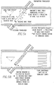
- Transit time ultrasonic meters measure the travel times of pulses of ultrasonic energy transiting from a transmitting transducer to a receiving transducer.
- a transmitting transducer has generated a pulse that is traveling diagonally across the flow stream in the direction of flow.
- the pulse's transit time is given by the quotient of the distance between transducers and the propagation velocity of the ultrasound.
- the propagation velocity is the sum of the velocity of ultrasound in the fluid at rest and the fluid velocity projected onto the acoustic path.
- the propagation velocity is the difference between the velocity of ultrasound in the fluid at rest and the fluid velocity projected onto the acoustic path.
- the two transit time measurements yield two equations in two unknowns: the ultrasound velocity in the fluid at rest and the fluid velocity projected onto the acoustic path.
- the fluid velocity projected onto the acoustic path is determined not only by the projection of the average axial velocity (the variable that needs to be measured) but also the net projection from the multiple turbulent eddies that accelerate or retard the pulse on its way.
- the transmission in the opposite direction is also affected by the turbulence, but not generally by the same eddies (which may have moved on between transmissions). For the condition illustrated in Figure 5A , therefore, multiple measurements are needed to average out the effects of the turbulent eddies and thereby to determine the average axial fluid velocity along the path.
- the turbulence conditioner design should allow the passage of only those eddies which are significantly smaller than the aperture diameter and should break up larger eddies such that only eddies whose diameter is significantly smaller than the aperture are produced.
- the random deviations of flow samples of the ultrasonic meter 14 are made small by reducing the turbulent eddy sizes such that they are effectively averaged within the acoustic beams of the meter 14.
- the data of Figure 6 show the reduction produced by a 1 ⁇ 4 inch honeycomb turbulence conditioner 16, as shown in Figure 1 , in a 6 inch duplex ultrasonic meter 14 (the duplex meter 14 consists of two essentially independent meters 14 of four paths each), having transducer apertures 18 of approximately 1 ⁇ 2 inch diameter.
- the turbulence conditioner 16 produces standard deviations for individual flow samples of approximately 1 ⁇ 2% (versus a standard deviation of 1.2%, which would be expected from the same meter 14 operating in a straight pipe 12 without the turbulence conditioner 16).
- the reduction in the standard deviation in the flow samples translates into improved proving performance.
- the proving performance with the honeycomb conditioner 16 was measured by examining the range of meter 14 factors in sets of 5 proving runs each. Ten sets of 5 run trials were carried out for each of the two 4 path meters 14, at two different flow rates and with two different proving volumes a total of thirty 5 run sets for each of the two meters 14. For twenty of these run sets a prover volume of 20 barrels was employed, 10 sets each at 3400 and 2700 barrels per hour respectively. For the remaining runs a prover volume of 10 barrels with a flow rate of 3400 barrels per hour was employed. Proving volumes in the 10 to 20 barrel range are typical for the two flow rates.
- Proving data collected during the tests with the turbulence conditioner 16 of Figure 1 are presented in Figure 7 .
- the abscissa of Figure 7 is the statistical characterization of the flow variability developed in a preceding section: 2 ⁇ ⁇ mean , twice the quotient of the standard deviation of the individual flow samples measured during a proving run and the square root of the number of samples N taken during that run. N is computed as the product of the ultrasonic meter 14 sample rate (about 50 Hz) and the duration of the run.
- the ordinate of Figure 7 is the average range of the proving runs. A linear trend of the data shows that the average range of the data from a set of 5 proving runs is approximately equal to 2 ⁇ ⁇ mean .
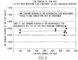
- Figure 8 shows the percentage of 5 run prove sets that were actually successful that met the requirement of 0.05% range for 5 proves. As projected above, the figure shows that, when 2 ⁇ ⁇ mean is 0.025% or less, 100% of the 5 run sets were successful. When 2 ⁇ ⁇ mean is in the 0.045% range, about 50% to 70% of the 5 run sets are successful. These latter results are also roughly in accordance with statistical predictions.
- reducing nozzles 24 can be applied with the turbulence conditioners 16 described herein to enhance proving performance still further.
- Figure 4 shows a tube bundle turbulence conditioner 16 meeting the dimensional parameters prescribed herein upstream of a reducing nozzle 24, with an ultrasonic meter 14 downstream of the nozzle 24.
- An expanding diffuser downstream of the meter 14 restores the upstream pipe 12 diameter at minimal loss.
- the ultrasonic flow meter 14 is located in the cylindrical throat of the nozzle 24, which increases the mean fluid velocity seen by the meter 14 as the reciprocal of the beta ratio squared.
- the beta ratio is the quotient of the nozzle 24 throat diameter and the upstream pipe 12 diameter.
- the reduction in turbulence comes about because, while the nozzle 24 increases the average fluid velocity, it does not significantly alter the tangential velocities of the turbulent eddies. Thus the turbulence as a percentage of average fluid velocity is reduced.
- Tests have demonstrated the ability of nozzles 24 having a beta ratio of 0.67 to reduce the standard deviation of individual flow measurements by about a factor of two, as might be expected since (1/0.67) 2 ⁇ 1 ⁇ 2.
- the use of a nozzle 24 downstream of the turbulence conditioner 16 but upstream of the flowmeter 14 would reduce the standard deviations of the flow of Figure 6 from 0.5% to 0.25%.
- the arrangement would halve the (2 ⁇ mean ) data of Figures 7 and 8 , leading to 100% success even with the 10 barrel proving volume.
- Figure 9 shows larger holes in some part of the cross section of the conditioner 16.
- Figures 10 and 11 show the openings 22 are not of equal dimensions, but vary.
Landscapes
- Physics & Mathematics (AREA)
- Fluid Mechanics (AREA)
- General Physics & Mathematics (AREA)
- Electromagnetism (AREA)
- Measuring Volume Flow (AREA)
Claims (11)
- Vorrichtung (10) zur Bestimmung der Fluidströmung in einem Rohr (12), die Folgendes umfasst:einen Ultraschall-Durchflussmesser (14), der mit dem Inneren des Rohrs (12) über mindestens ein Paar von Schlitzen (18) in Verbindung steht, wobei jeder Schlitz (18) des einen Paares von Schlitzen (18) einen effektiven Durchmesser hat; undeinen Turbulenzkonditionierer (16), der in dem Rohr (12) angeordnet ist und Öffnungen (22) aufweist, wobei der Abstand zwischen den Öffnungen (22) geringer ist als der effektive Durchmesser des Schlitzes (18);dadurch gekennzeichnet, dass sich der Konditionierer (16) über den Innendurchmesser des Rohrs (12) erstreckt und eine axiale Länge aufweist, die das 5- bis 20-fache des Abstands beträgt.
- Vorrichtung (10) nach Anspruch 1, wobei der Konditionierer (16) Wände (20) zwischen den Öffnungen (22) aufweist, wobei die Wände (20) eine Dicke zwischen 1/4 bis 1/10 des Abstands aufweist.
- Vorrichtung (10) nach Anspruch 1 oder 2, wobei der Messer (14) stromabwärts von dem Konditionierer (16) um bis zu 3 Rohrinnendurchmessern angeordnet ist.
- Vorrichtung (10) nach einem der vorangehenden Ansprüche, wobei die Öffnungen (22) entweder einen Querschnitt haben, der zwei- oder mehrseitig ist, oder einen kreisförmigen Querschnitt haben.
- Vorrichtung (10) nach einem der vorangehenden Ansprüche, die ferner einen Filter (26) umfasst, der in dem Rohr (12) stromaufwärts von dem Konditionierer (16) angeordnet ist.
- Vorrichtung (10) nach einem der vorangehenden Ansprüche, die ferner eine Düse (24) umfasst, die in dem Rohr (12) stromaufwärts von dem Ultraschall-Durchflussmesser (14) und stromabwärts von dem Konditionierer (16) angeordnet ist.
- Vorrichtung (10) nach einem der vorangehenden Ansprüche, wobei der Abstand eine Funktion der maximalen Geschwindigkeit des Ultraschall-Durchflussmessers (14) ist.
- Verfahren zum Bestimmen der Fluidströmung in einem Rohr (12), das die folgenden Schritte umfasst:
Strömen von Fluid durch einen Turbulenzkonditionierer (16), der in dem Rohr (12) angeordnet ist und sich über dessen Innendurchmesser erstreckt, wobei der Konditionierer (16) Öffnungen (22) aufweist, wobei der Abstand zwischen den Öffnungen (22) kleiner als ein effektiver Durchmesser eines Schlitzes (18) eines Ultraschall-Durchflussmessers ist, der mit dem Inneren des Rohrs (12) durch den Schlitz (18) in Verbindung steht, und wobei die axiale Länge des Konditionierers (16) das 5- bis 20-fache des Abstands beträgt; und Messen des Durchflusses mit dem Messer (14). - Verfahren nach Anspruch 8, wobei das Strömen des Fluids durch einen Turbulenzkonditionierer (16) den Schritt des Strömens des Fluids durch den Turbulenzkonditionierer (16) enthält, wobei der Konditionierer (16) Wände (20) zwischen den Öffnungen (22) mit einer Dicke zwischen 1/4 und 1/10 des Abstands aufweist.
- Verfahren zum Gestalten
eines Turbulenzkonditionierers (16) zur Verwendung mit einem Ultraschall-Durchflussmesser (14) in einem Rohr (12), das die folgenden Schritte umfasst:Identifizieren eines effektiven Durchmessers eines Schlitzes (18) in dem Rohr (12), durch den der Durchflussmesser mit dem Inneren des Rohrs (12) in Verbindung steht;Bestimmen eines Abstands zwischen Löchern in dem Konditionierer (16), wobei der Abstand kleiner als der effektive Durchmesser des Schlitzes (18) ist;Bestimmen einer axialen Breite des Konditionierers (16), die gleich einem Innendurchmesser des Rohrs (12) ist; undBestimmen einer axialen Länge des Konditionierers (16), die das 5- bis 20-fache des Abstands beträgt. - Verfahren nach Anspruch 10, ferner umfassend das Bestimmen einer Dicke von Wänden (20) zwischen den Öffnungen (22), wobei die Dicke zwischen 1/4 bis 1/10 des Abstands liegt.
Applications Claiming Priority (2)
| Application Number | Priority Date | Filing Date | Title |
|---|---|---|---|
| US12/002,270 US7823462B2 (en) | 2007-12-14 | 2007-12-14 | Turbulence conditioner for transit time ultrasonic flow meters and method |
| PCT/US2008/013263 WO2009078910A1 (en) | 2007-12-14 | 2008-12-02 | Turbulence conditioner for transit time ultrasonic flow meters and method |
Publications (3)
| Publication Number | Publication Date |
|---|---|
| EP2232342A1 EP2232342A1 (de) | 2010-09-29 |
| EP2232342A4 EP2232342A4 (de) | 2011-07-13 |
| EP2232342B1 true EP2232342B1 (de) | 2020-04-22 |
Family
ID=40751504
Family Applications (1)
| Application Number | Title | Priority Date | Filing Date |
|---|---|---|---|
| EP08862021.6A Active EP2232342B1 (de) | 2007-12-14 | 2008-12-02 | Turbulenzaufbereitungsvorrichtung für transitzeit-ultraschallströmungsmesser und verfahren |
Country Status (7)
| Country | Link |
|---|---|
| US (2) | US7823462B2 (de) |
| EP (1) | EP2232342B1 (de) |
| KR (1) | KR101224215B1 (de) |
| CN (1) | CN101918902B (de) |
| BR (1) | BRPI0821130A2 (de) |
| CA (1) | CA2707398C (de) |
| WO (1) | WO2009078910A1 (de) |
Cited By (1)
| Publication number | Priority date | Publication date | Assignee | Title |
|---|---|---|---|---|
| US12578216B2 (en) | 2021-03-17 | 2026-03-17 | Woodward, Inc. | Ultrasonic mass fuel flow meter |
Families Citing this family (35)
| Publication number | Priority date | Publication date | Assignee | Title |
|---|---|---|---|---|
| PL2375224T3 (pl) * | 2010-03-18 | 2016-07-29 | Sick Engineering Gmbh | Ultradźwiękowe urządzenie pomiarowe i sposób pomiaru prędkości przepływu płynu |
| US20120074069A1 (en) * | 2010-07-19 | 2012-03-29 | Hanilton Sundstrand Corporation | Smart filter monitor |
| US9003895B2 (en) * | 2010-10-25 | 2015-04-14 | Cameron International Corporation | Conditioner, apparatus and method |
| US8347733B2 (en) * | 2010-10-25 | 2013-01-08 | Cameron International Corporation | Conditioner, apparatus and method |
| US8438936B2 (en) | 2011-06-03 | 2013-05-14 | General Electric Company | Sensor assembly including a collar for mounting sensors to a pipeline |
| USD691241S1 (en) * | 2011-07-07 | 2013-10-08 | Endress + Hauser Flowtec Ag | Four tube coriollis flow meter |
| GB2504295B (en) | 2012-07-24 | 2019-07-31 | Titan Entpr Ltd | Flowmeter with annular passage |
| US9151649B2 (en) * | 2012-10-19 | 2015-10-06 | Daniel Measurement And Control, Inc. | Ultrasonic flow metering system with an upstream pressure transducer |
| SE538092C2 (sv) * | 2012-12-04 | 2016-03-01 | Scania Cv Ab | Luftmassemätarrör |
| US9068870B2 (en) * | 2013-02-27 | 2015-06-30 | Daniel Measurement And Control, Inc. | Ultrasonic flow metering with laminar to turbulent transition flow control |
| CN103196504B (zh) * | 2013-03-21 | 2015-01-14 | 浙江大学 | 一种多声道超声波流量测量方法及装置 |
| US9891085B2 (en) * | 2013-10-11 | 2018-02-13 | General Electric Company | Ultrasound fuel flow sensing and control |
| US9372106B2 (en) * | 2014-01-14 | 2016-06-21 | General Electric Company | Non-circular flowmeter |
| US9297679B2 (en) * | 2014-01-14 | 2016-03-29 | General Electric Company | Flowmeter with a flow conditioner formed by a protrusion having restriction provided upstream of the measurement section |
| JP6214044B2 (ja) * | 2014-02-07 | 2017-10-18 | 愛知時計電機株式会社 | 超音波ガスメータ |
| DE102014106927A1 (de) * | 2014-05-16 | 2015-11-19 | Endress + Hauser Flowtec Ag | Messgerät, insbesondere Durchflussmessgerät, und Verfahren zur zur Herstellung eines Messrohres für ein Messgerät |
| KR102253890B1 (ko) | 2014-12-03 | 2021-05-20 | 대우조선해양 주식회사 | 관내 액체 홀드업 측정장치 및 측정방법 |
| KR102267661B1 (ko) | 2014-12-05 | 2021-06-22 | 대우조선해양 주식회사 | 관내 유동의 볼륨 프랙션 측정장치 및 측정방법 |
| KR102292687B1 (ko) | 2014-12-23 | 2021-08-24 | 대우조선해양 주식회사 | 관내 유동의 볼륨 프랙션 측정장치 및 측정방법 |
| CN104793013A (zh) * | 2015-04-12 | 2015-07-22 | 吉林大学 | 蜂窝管在分子-电子感应式加速度计上的应用 |
| JP6368916B2 (ja) * | 2015-04-16 | 2018-08-08 | パナソニックIpマネジメント株式会社 | 流量計測装置 |
| CN105444828B (zh) * | 2015-08-21 | 2018-07-10 | 浙江天信超声技术有限公司 | 超声波流量计的整流器的设计方法 |
| US10190900B2 (en) * | 2017-04-05 | 2019-01-29 | Canada Pipeline Accessories Company, Ltd. | Method of fluid flow measurement using nozzle bank |
| EP3821214B1 (de) * | 2018-07-11 | 2023-11-01 | Micro Motion, Inc. | Verfahren zum betrieb eines diagnosewerkzeugs für durchflussmesser und diagnosewerkzeuge zur konfiguration eines durchflussmessersystems |
| US10852173B2 (en) * | 2018-12-18 | 2020-12-01 | Sensia Llc | Flowmeters and methods of manufacture |
| CN110296912B (zh) * | 2019-06-19 | 2020-07-21 | 北京理工大学 | 基于超声的粉尘云团扩散动态湍流动能的检测系统及方法 |
| US11181406B2 (en) | 2019-12-03 | 2021-11-23 | Woodward, Inc. | Ultrasonic mass fuel flow meter |
| KR20210115657A (ko) | 2020-03-16 | 2021-09-27 | 재단법인한국조선해양기자재연구원 | 선박평형수 대표샘플 취득을 위한 층류형성장치 |
| US11668818B2 (en) | 2020-08-07 | 2023-06-06 | Woodward, Inc. | Ultrasonic position sensor |
| US11885655B2 (en) | 2020-08-07 | 2024-01-30 | Woodward, Inc. | Ultrasonic flow meter having flow conditioning arrangements for flow controlling in a linear fluid conduit |
| US12140669B2 (en) | 2020-08-07 | 2024-11-12 | Woodward, Inc. | Ratio metric position sensor and control system |
| EP4273511A1 (de) * | 2022-05-04 | 2023-11-08 | Sartorius Stedim Biotech GmbH | Vorrichtung zum anordnen an einer fluidführenden leitung und zum anbringen einer durchflussmesseinrichtung, und verfahren zur erfassung einer messgrösse des von einer leitung geführten fluids |
| CN116754790B (zh) * | 2023-06-01 | 2025-06-24 | 武汉理工大学 | 一种旋涡水域流速测量装置及方法 |
| US20250207735A1 (en) * | 2023-12-26 | 2025-06-26 | Honeywell International Inc. | Front-insert assembly method and apparatus for flow conditioner |
| CN117871672A (zh) * | 2024-01-12 | 2024-04-12 | 中国华能集团清洁能源技术研究院有限公司 | 管道强度确定方法、装置、电子设备及存储介质 |
Family Cites Families (12)
| Publication number | Priority date | Publication date | Assignee | Title |
|---|---|---|---|---|
| GB2218518A (en) * | 1988-05-10 | 1989-11-15 | Scheme Engineering Ltd | Ultrasonic flow meter with welded transducer mountings |
| EP0483206B1 (de) * | 1989-07-20 | 1995-02-01 | Salford University Business Services Limited | Strömungskonditionierer |
| US6128072A (en) * | 1998-04-23 | 2000-10-03 | Nova Gas Transmission Ltd. | Optical flow meter integrally mounted to a rigid plate with direct optical access to the interior of a pipe |
| US6796173B1 (en) * | 1998-10-09 | 2004-09-28 | Fti Flow Technology, Inc. | Fuel flowmeter |
| MY127673A (en) * | 1999-03-17 | 2006-12-29 | Matsushita Electric Industrial Co Ltd | Ultrasonic flow meter |
| US6494105B1 (en) * | 1999-05-07 | 2002-12-17 | James E. Gallagher | Method for determining flow velocity in a channel |
| US6119528A (en) * | 1999-07-29 | 2000-09-19 | Lake Monitors, Inc | System for measuring liquid flow through a metering device |
| US6647806B1 (en) * | 2000-07-14 | 2003-11-18 | Caldon, Inc. | Turbulence conditioner for use with transit time ultrasonic flowmeters |
| EP1188935A2 (de) * | 2000-09-15 | 2002-03-20 | Daniel Industries, Inc., | Strömungsgleichrichter eines feuchten Gases |
| JP3655569B2 (ja) * | 2001-09-06 | 2005-06-02 | 大陽日酸株式会社 | ガス成分濃度測定方法及び装置 |
| DE10240975B4 (de) * | 2002-09-02 | 2007-02-01 | Hydrometer Gmbh | Meßwertgeber für einen Ultraschall-Durchflussmesser |
| US20070151362A1 (en) * | 2003-12-26 | 2007-07-05 | Michitsugu Mori | Ultrasonic flowmeter, wedge for ultrasonic flowmeter, method for setting ultrasonic transmitting/receiving unit, and ultrasonic transmitting/receiving unit |
-
2007
- 2007-12-14 US US12/002,270 patent/US7823462B2/en active Active
-
2008
- 2008-12-02 CA CA2707398A patent/CA2707398C/en not_active Expired - Fee Related
- 2008-12-02 EP EP08862021.6A patent/EP2232342B1/de active Active
- 2008-12-02 CN CN200880125090XA patent/CN101918902B/zh not_active Expired - Fee Related
- 2008-12-02 KR KR1020107015637A patent/KR101224215B1/ko not_active Expired - Fee Related
- 2008-12-02 WO PCT/US2008/013263 patent/WO2009078910A1/en not_active Ceased
- 2008-12-02 BR BRPI0821130-2A patent/BRPI0821130A2/pt not_active IP Right Cessation
-
2010
- 2010-08-31 US US12/807,193 patent/US8065785B2/en active Active
Non-Patent Citations (1)
| Title |
|---|
| None * |
Cited By (1)
| Publication number | Priority date | Publication date | Assignee | Title |
|---|---|---|---|---|
| US12578216B2 (en) | 2021-03-17 | 2026-03-17 | Woodward, Inc. | Ultrasonic mass fuel flow meter |
Also Published As
| Publication number | Publication date |
|---|---|
| US7823462B2 (en) | 2010-11-02 |
| KR20100101144A (ko) | 2010-09-16 |
| EP2232342A1 (de) | 2010-09-29 |
| CA2707398C (en) | 2012-11-13 |
| EP2232342A4 (de) | 2011-07-13 |
| CN101918902A (zh) | 2010-12-15 |
| KR101224215B1 (ko) | 2013-01-21 |
| US20090151472A1 (en) | 2009-06-18 |
| WO2009078910A1 (en) | 2009-06-25 |
| BRPI0821130A2 (pt) | 2015-06-16 |
| CA2707398A1 (en) | 2009-06-25 |
| US20110005335A1 (en) | 2011-01-13 |
| CN101918902B (zh) | 2013-08-28 |
| US8065785B2 (en) | 2011-11-29 |
Similar Documents
| Publication | Publication Date | Title |
|---|---|---|
| EP2232342B1 (de) | Turbulenzaufbereitungsvorrichtung für transitzeit-ultraschallströmungsmesser und verfahren | |
| KR100694937B1 (ko) | 초음파식 유체 계측 장치 | |
| US4365518A (en) | Flow straighteners in axial flowmeters | |
| EP1831649B1 (de) | Ultraschall-durchflussmesser mit drucksensor | |
| US6647806B1 (en) | Turbulence conditioner for use with transit time ultrasonic flowmeters | |
| EP2510317B1 (de) | Strömungsmesser und verfahren | |
| EP1217339A2 (de) | Schalldämpfer und Verfahren zur Verwendung mit einem Ultraschalldurchflussmesser | |
| US20030094052A1 (en) | Dual function flow conditioner and check meter | |
| WO2007104708A2 (de) | Vorrichtung zur bestimmung und/oder überwachung des volumen- oder des massedurchflusses eines mediums in einer rohrleitung | |
| EP3273205B1 (de) | Verfahren und anordnung zur ultraschall-clamp-on-durchflussmessung und körper zur realisierung der messung | |
| CN101294833A (zh) | 超声波式流体测量装置 | |
| DE10314916A1 (de) | Vorrichtung zur Bestimmung und/oder Überwachung des Volumen- und/oder Massenstroms eines Mediums | |
| EP1728054A1 (de) | Ultraschall-str mungssensor mit wandlerarray und reflextionsfläche | |
| EP1931948B1 (de) | Vorrichtung zur bestimmung oder überwachung des volumen- oder massedurchflusses eines mediums durch eine rohrleitung | |
| DE10229925A1 (de) | Vorrichtung zum Messen der Strömungsgeschwindigkeit und/oder des Durchflusses eines Fluids | |
| EP2146189B1 (de) | Ultraschallmessung von Strömungsgeschwindigkeiten | |
| DE19503714A1 (de) | Anordnung zur Bestimmung der Strömungsgeschwindigkeit eines Fluides in Rohren mit kreisförmigem Querschnitt mittels Ultraschall | |
| EP0505483A1 (de) | Ultraschall-gas-/flüssigkeits-durchflussmesser. | |
| EP1955019B1 (de) | Ultraschallmessvorrichtung zur bestimmung und/oder überwachung des volumen- oder massedurchflusses eines mediums durch eine rohrleitung | |
| WO2006000546A1 (de) | Verfahren zur kalibrierung von ultraschall-clamp-on-durchflussmessgeräten | |
| EP0650035A1 (de) | Vorrichtung zur Durchflussmessung | |
| EP3748309B1 (de) | Ultraschalldurchflussmessgerät, verwendung eines ultraschalldurchflussmessgerätes in einem absperrorgan und absperrorgan | |
| EP1826537A2 (de) | Vorrichtung zur Ermittlung der Strömungsgeschwindigkeit eines Fluides oder Gases in einem Rohr | |
| US20210333138A1 (en) | Water meter assembly with taper for minimizing head loss | |
| DE202024106930U1 (de) | Durchflussmesser mit der Verwendung von Ultraschall |
Legal Events
| Date | Code | Title | Description |
|---|---|---|---|
| PUAI | Public reference made under article 153(3) epc to a published international application that has entered the european phase |
Free format text: ORIGINAL CODE: 0009012 |
|
| 17P | Request for examination filed |
Effective date: 20100714 |
|
| AK | Designated contracting states |
Kind code of ref document: A1 Designated state(s): AT BE BG CH CY CZ DE DK EE ES FI FR GB GR HR HU IE IS IT LI LT LU LV MC MT NL NO PL PT RO SE SI SK TR |
|
| AX | Request for extension of the european patent |
Extension state: AL BA MK RS |
|
| DAX | Request for extension of the european patent (deleted) | ||
| A4 | Supplementary search report drawn up and despatched |
Effective date: 20110610 |
|
| RIC1 | Information provided on ipc code assigned before grant |
Ipc: G01F 1/66 20060101ALI20110606BHEP Ipc: G05B 13/02 20060101AFI20090709BHEP |
|
| 17Q | First examination report despatched |
Effective date: 20120229 |
|
| RIC1 | Information provided on ipc code assigned before grant |
Ipc: G01F 15/00 20060101AFI20120928BHEP Ipc: G01F 1/66 20060101ALI20120928BHEP |
|
| RAP1 | Party data changed (applicant data changed or rights of an application transferred) |
Owner name: CAMERON TECHNOLOGIES LIMITED |
|
| GRAP | Despatch of communication of intention to grant a patent |
Free format text: ORIGINAL CODE: EPIDOSNIGR1 |
|
| STAA | Information on the status of an ep patent application or granted ep patent |
Free format text: STATUS: GRANT OF PATENT IS INTENDED |
|
| INTG | Intention to grant announced |
Effective date: 20191107 |
|
| GRAS | Grant fee paid |
Free format text: ORIGINAL CODE: EPIDOSNIGR3 |
|
| GRAA | (expected) grant |
Free format text: ORIGINAL CODE: 0009210 |
|
| STAA | Information on the status of an ep patent application or granted ep patent |
Free format text: STATUS: THE PATENT HAS BEEN GRANTED |
|
| RAP1 | Party data changed (applicant data changed or rights of an application transferred) |
Owner name: SENSIA NETHERLANDS B.V. |
|
| AK | Designated contracting states |
Kind code of ref document: B1 Designated state(s): AT BE BG CH CY CZ DE DK EE ES FI FR GB GR HR HU IE IS IT LI LT LU LV MC MT NL NO PL PT RO SE SI SK TR |
|
| REG | Reference to a national code |
Ref country code: GB Ref legal event code: FG4D |
|
| REG | Reference to a national code |
Ref country code: CH Ref legal event code: EP |
|
| REG | Reference to a national code |
Ref country code: IE Ref legal event code: FG4D |
|
| REG | Reference to a national code |
Ref country code: DE Ref legal event code: R096 Ref document number: 602008062560 Country of ref document: DE |
|
| REG | Reference to a national code |
Ref country code: AT Ref legal event code: REF Ref document number: 1260730 Country of ref document: AT Kind code of ref document: T Effective date: 20200515 |
|
| REG | Reference to a national code |
Ref country code: NL Ref legal event code: FP |
|
| REG | Reference to a national code |
Ref country code: NO Ref legal event code: T2 Effective date: 20200422 |
|
| REG | Reference to a national code |
Ref country code: LT Ref legal event code: MG4D |
|
| PG25 | Lapsed in a contracting state [announced via postgrant information from national office to epo] |
Ref country code: PT Free format text: LAPSE BECAUSE OF FAILURE TO SUBMIT A TRANSLATION OF THE DESCRIPTION OR TO PAY THE FEE WITHIN THE PRESCRIBED TIME-LIMIT Effective date: 20200824 Ref country code: SE Free format text: LAPSE BECAUSE OF FAILURE TO SUBMIT A TRANSLATION OF THE DESCRIPTION OR TO PAY THE FEE WITHIN THE PRESCRIBED TIME-LIMIT Effective date: 20200422 Ref country code: GR Free format text: LAPSE BECAUSE OF FAILURE TO SUBMIT A TRANSLATION OF THE DESCRIPTION OR TO PAY THE FEE WITHIN THE PRESCRIBED TIME-LIMIT Effective date: 20200723 Ref country code: LT Free format text: LAPSE BECAUSE OF FAILURE TO SUBMIT A TRANSLATION OF THE DESCRIPTION OR TO PAY THE FEE WITHIN THE PRESCRIBED TIME-LIMIT Effective date: 20200422 Ref country code: FI Free format text: LAPSE BECAUSE OF FAILURE TO SUBMIT A TRANSLATION OF THE DESCRIPTION OR TO PAY THE FEE WITHIN THE PRESCRIBED TIME-LIMIT Effective date: 20200422 Ref country code: IS Free format text: LAPSE BECAUSE OF FAILURE TO SUBMIT A TRANSLATION OF THE DESCRIPTION OR TO PAY THE FEE WITHIN THE PRESCRIBED TIME-LIMIT Effective date: 20200822 |
|
| REG | Reference to a national code |
Ref country code: AT Ref legal event code: MK05 Ref document number: 1260730 Country of ref document: AT Kind code of ref document: T Effective date: 20200422 |
|
| PG25 | Lapsed in a contracting state [announced via postgrant information from national office to epo] |
Ref country code: LV Free format text: LAPSE BECAUSE OF FAILURE TO SUBMIT A TRANSLATION OF THE DESCRIPTION OR TO PAY THE FEE WITHIN THE PRESCRIBED TIME-LIMIT Effective date: 20200422 Ref country code: HR Free format text: LAPSE BECAUSE OF FAILURE TO SUBMIT A TRANSLATION OF THE DESCRIPTION OR TO PAY THE FEE WITHIN THE PRESCRIBED TIME-LIMIT Effective date: 20200422 Ref country code: BG Free format text: LAPSE BECAUSE OF FAILURE TO SUBMIT A TRANSLATION OF THE DESCRIPTION OR TO PAY THE FEE WITHIN THE PRESCRIBED TIME-LIMIT Effective date: 20200722 |
|
| REG | Reference to a national code |
Ref country code: DE Ref legal event code: R097 Ref document number: 602008062560 Country of ref document: DE |
|
| PG25 | Lapsed in a contracting state [announced via postgrant information from national office to epo] |
Ref country code: AT Free format text: LAPSE BECAUSE OF FAILURE TO SUBMIT A TRANSLATION OF THE DESCRIPTION OR TO PAY THE FEE WITHIN THE PRESCRIBED TIME-LIMIT Effective date: 20200422 Ref country code: EE Free format text: LAPSE BECAUSE OF FAILURE TO SUBMIT A TRANSLATION OF THE DESCRIPTION OR TO PAY THE FEE WITHIN THE PRESCRIBED TIME-LIMIT Effective date: 20200422 Ref country code: CZ Free format text: LAPSE BECAUSE OF FAILURE TO SUBMIT A TRANSLATION OF THE DESCRIPTION OR TO PAY THE FEE WITHIN THE PRESCRIBED TIME-LIMIT Effective date: 20200422 Ref country code: RO Free format text: LAPSE BECAUSE OF FAILURE TO SUBMIT A TRANSLATION OF THE DESCRIPTION OR TO PAY THE FEE WITHIN THE PRESCRIBED TIME-LIMIT Effective date: 20200422 Ref country code: IT Free format text: LAPSE BECAUSE OF FAILURE TO SUBMIT A TRANSLATION OF THE DESCRIPTION OR TO PAY THE FEE WITHIN THE PRESCRIBED TIME-LIMIT Effective date: 20200422 Ref country code: ES Free format text: LAPSE BECAUSE OF FAILURE TO SUBMIT A TRANSLATION OF THE DESCRIPTION OR TO PAY THE FEE WITHIN THE PRESCRIBED TIME-LIMIT Effective date: 20200422 Ref country code: DK Free format text: LAPSE BECAUSE OF FAILURE TO SUBMIT A TRANSLATION OF THE DESCRIPTION OR TO PAY THE FEE WITHIN THE PRESCRIBED TIME-LIMIT Effective date: 20200422 |
|
| PG25 | Lapsed in a contracting state [announced via postgrant information from national office to epo] |
Ref country code: SK Free format text: LAPSE BECAUSE OF FAILURE TO SUBMIT A TRANSLATION OF THE DESCRIPTION OR TO PAY THE FEE WITHIN THE PRESCRIBED TIME-LIMIT Effective date: 20200422 Ref country code: PL Free format text: LAPSE BECAUSE OF FAILURE TO SUBMIT A TRANSLATION OF THE DESCRIPTION OR TO PAY THE FEE WITHIN THE PRESCRIBED TIME-LIMIT Effective date: 20200422 |
|
| PLBE | No opposition filed within time limit |
Free format text: ORIGINAL CODE: 0009261 |
|
| STAA | Information on the status of an ep patent application or granted ep patent |
Free format text: STATUS: NO OPPOSITION FILED WITHIN TIME LIMIT |
|
| 26N | No opposition filed |
Effective date: 20210125 |
|
| PG25 | Lapsed in a contracting state [announced via postgrant information from national office to epo] |
Ref country code: SI Free format text: LAPSE BECAUSE OF FAILURE TO SUBMIT A TRANSLATION OF THE DESCRIPTION OR TO PAY THE FEE WITHIN THE PRESCRIBED TIME-LIMIT Effective date: 20200422 |
|
| REG | Reference to a national code |
Ref country code: CH Ref legal event code: PL |
|
| PG25 | Lapsed in a contracting state [announced via postgrant information from national office to epo] |
Ref country code: MC Free format text: LAPSE BECAUSE OF FAILURE TO SUBMIT A TRANSLATION OF THE DESCRIPTION OR TO PAY THE FEE WITHIN THE PRESCRIBED TIME-LIMIT Effective date: 20200422 |
|
| REG | Reference to a national code |
Ref country code: BE Ref legal event code: MM Effective date: 20201231 |
|
| PG25 | Lapsed in a contracting state [announced via postgrant information from national office to epo] |
Ref country code: LU Free format text: LAPSE BECAUSE OF NON-PAYMENT OF DUE FEES Effective date: 20201202 Ref country code: IE Free format text: LAPSE BECAUSE OF NON-PAYMENT OF DUE FEES Effective date: 20201202 |
|
| PG25 | Lapsed in a contracting state [announced via postgrant information from national office to epo] |
Ref country code: LI Free format text: LAPSE BECAUSE OF NON-PAYMENT OF DUE FEES Effective date: 20201231 Ref country code: CH Free format text: LAPSE BECAUSE OF NON-PAYMENT OF DUE FEES Effective date: 20201231 |
|
| PG25 | Lapsed in a contracting state [announced via postgrant information from national office to epo] |
Ref country code: TR Free format text: LAPSE BECAUSE OF FAILURE TO SUBMIT A TRANSLATION OF THE DESCRIPTION OR TO PAY THE FEE WITHIN THE PRESCRIBED TIME-LIMIT Effective date: 20200422 Ref country code: MT Free format text: LAPSE BECAUSE OF FAILURE TO SUBMIT A TRANSLATION OF THE DESCRIPTION OR TO PAY THE FEE WITHIN THE PRESCRIBED TIME-LIMIT Effective date: 20200422 Ref country code: CY Free format text: LAPSE BECAUSE OF FAILURE TO SUBMIT A TRANSLATION OF THE DESCRIPTION OR TO PAY THE FEE WITHIN THE PRESCRIBED TIME-LIMIT Effective date: 20200422 |
|
| PG25 | Lapsed in a contracting state [announced via postgrant information from national office to epo] |
Ref country code: BE Free format text: LAPSE BECAUSE OF NON-PAYMENT OF DUE FEES Effective date: 20201231 |
|
| P01 | Opt-out of the competence of the unified patent court (upc) registered |
Effective date: 20230522 |
|
| PGFP | Annual fee paid to national office [announced via postgrant information from national office to epo] |
Ref country code: GB Payment date: 20231207 Year of fee payment: 16 |
|
| PGFP | Annual fee paid to national office [announced via postgrant information from national office to epo] |
Ref country code: NO Payment date: 20231212 Year of fee payment: 16 Ref country code: NL Payment date: 20231215 Year of fee payment: 16 Ref country code: FR Payment date: 20231212 Year of fee payment: 16 Ref country code: DE Payment date: 20231212 Year of fee payment: 16 |
|
| REG | Reference to a national code |
Ref country code: DE Ref legal event code: R119 Ref document number: 602008062560 Country of ref document: DE |
|
| REG | Reference to a national code |
Ref country code: NL Ref legal event code: MM Effective date: 20250101 |
|
| GBPC | Gb: european patent ceased through non-payment of renewal fee |
Effective date: 20241202 |
|
| PG25 | Lapsed in a contracting state [announced via postgrant information from national office to epo] |
Ref country code: NL Free format text: LAPSE BECAUSE OF NON-PAYMENT OF DUE FEES Effective date: 20250101 |
|
| PG25 | Lapsed in a contracting state [announced via postgrant information from national office to epo] |
Ref country code: DE Free format text: LAPSE BECAUSE OF NON-PAYMENT OF DUE FEES Effective date: 20250701 |
|
| PG25 | Lapsed in a contracting state [announced via postgrant information from national office to epo] |
Ref country code: NO Free format text: LAPSE BECAUSE OF NON-PAYMENT OF DUE FEES Effective date: 20241231 |
|
| PG25 | Lapsed in a contracting state [announced via postgrant information from national office to epo] |
Ref country code: GB Free format text: LAPSE BECAUSE OF NON-PAYMENT OF DUE FEES Effective date: 20241202 |
|
| PG25 | Lapsed in a contracting state [announced via postgrant information from national office to epo] |
Ref country code: FR Free format text: LAPSE BECAUSE OF NON-PAYMENT OF DUE FEES Effective date: 20241231 |