EP2232296B1 - System und Verfahren zum Ablenken eines Lenkflugkörpers - Google Patents
System und Verfahren zum Ablenken eines Lenkflugkörpers Download PDFInfo
- Publication number
- EP2232296B1 EP2232296B1 EP08871002A EP08871002A EP2232296B1 EP 2232296 B1 EP2232296 B1 EP 2232296B1 EP 08871002 A EP08871002 A EP 08871002A EP 08871002 A EP08871002 A EP 08871002A EP 2232296 B1 EP2232296 B1 EP 2232296B1
- Authority
- EP
- European Patent Office
- Prior art keywords
- target
- guided missile
- directed
- missile
- control node
- Prior art date
- Legal status (The legal status is an assumption and is not a legal conclusion. Google has not performed a legal analysis and makes no representation as to the accuracy of the status listed.)
- Active
Links
Images


Classifications
-
- G—PHYSICS
- G01—MEASURING; TESTING
- G01S—RADIO DIRECTION-FINDING; RADIO NAVIGATION; DETERMINING DISTANCE OR VELOCITY BY USE OF RADIO WAVES; LOCATING OR PRESENCE-DETECTING BY USE OF THE REFLECTION OR RERADIATION OF RADIO WAVES; ANALOGOUS ARRANGEMENTS USING OTHER WAVES
- G01S13/00—Systems using the reflection or reradiation of radio waves, e.g. radar systems; Analogous systems using reflection or reradiation of waves whose nature or wavelength is irrelevant or unspecified
- G01S13/88—Radar or analogous systems specially adapted for specific applications
-
- F—MECHANICAL ENGINEERING; LIGHTING; HEATING; WEAPONS; BLASTING
- F41—WEAPONS
- F41G—WEAPON SIGHTS; AIMING
- F41G7/00—Direction control systems for self-propelled missiles
- F41G7/20—Direction control systems for self-propelled missiles based on continuous observation of target position
- F41G7/22—Homing guidance systems
- F41G7/224—Deceiving or protecting means
-
- F—MECHANICAL ENGINEERING; LIGHTING; HEATING; WEAPONS; BLASTING
- F41—WEAPONS
- F41H—ARMOUR; ARMOURED TURRETS; ARMOURED OR ARMED VEHICLES; MEANS OF ATTACK OR DEFENCE, e.g. CAMOUFLAGE, IN GENERAL
- F41H11/00—Defence installations; Defence devices
- F41H11/02—Anti-aircraft or anti-guided missile or anti-torpedo defence installations or systems
-
- F—MECHANICAL ENGINEERING; LIGHTING; HEATING; WEAPONS; BLASTING
- F41—WEAPONS
- F41H—ARMOUR; ARMOURED TURRETS; ARMOURED OR ARMED VEHICLES; MEANS OF ATTACK OR DEFENCE, e.g. CAMOUFLAGE, IN GENERAL
- F41H13/00—Means of attack or defence not otherwise provided for
- F41H13/0043—Directed energy weapons, i.e. devices that direct a beam of high energy content toward a target for incapacitating or destroying the target
Definitions
- the present invention provides a ground-based anti-missile system.
- Exemplary features generally include a ground-based sensor array generating tracking data of a guided missile and a control node generating targeting data from the tracking data.
- Another exemplary feature includes a phased array directed-energy unit radiating the guided missile based on targeting data from the control node, where the radiation disrupts an electronic component of the guided missile such that the guided missile discontinues tracking its intended target.
- WO 2007/059508 discloses a system including one ore more sources for generating high 5 power broadband microwave radiation and coupled to an array of antenna elements.
- US 7,212,148 discloses a countermeasure system for jamming an attack unit.
- FIG. 3 representatively illustrates an operational flow chart in accordance with an exemplary embodiment of the present invention
- FIG. 5 representatively illustrates the effect of wave form beam spoiling in accordance with an exemplary embodiment of the present invention.
- phased array directed-energy units used in applications such as anti-missile defense of a fixed target, a water-borne vessel, vehicles, and/or the like.
- anti-missile system 100 may provide protection to a target 110 from one or more guided missiles 108 in a defined space; for example, a hemispherical space over a given area.
- a guided missile 108 fired at a target 110 may be tracked and engaged by anti-missile system 100 to divert the guided missile 108 from its target 110 .
- anti-missile system 100 may be deployed at an airport such that targets 110 ( i.e ., aircraft) are protected during take off and landing, when they are most vulnerable to a guided missile 108 attack.
- Anti-missile system 100 may be suitably configured to detect the launch of a guided missile 108 , alert a control node 104 , track the guided missile flight and/or relay this information to control node 104 throughout the duration of the guided missile flight. Control node 104 may then direct one or more phased array directed-energy units 106 to radiate guided missile 108 with electromagnetic (EM) radiation such that guided missile 108 discontinues tracking target 110 or fails to reach target 110 .
- EM radiation may be RF (radio frequency), microwave, millimeter wave, or any other suitable type of radiation.
- Ground-based sensor array 102 may be coupled to control node 104 via one or more wireline or wireless communication links 117 . Further, phased array directed-energy unit 106 may be coupled to control node 104 via one or more wireline or wireless communication links 117 .
- sensors 103 , 105 may comprise a plurality of infrared sensors that are able to detect low-level signatures (e.g ., a heat plume from a guided missile) in a high-clutter (i.e ., noisy) background environment.
- Each infrared sensor may, for example, ascertain angular coordinates of a guided missile 108 relative to the fixed location of the sensor.
- Infrared sensors may comprise, for example and without limitation: charge coupled device image sensors; focal plane array sensors; and/or the like, with a sufficient pixel count to have a desired pixel density and/or resolution to detect and track a guided missile in a defined space.
- Each of plurality of sensors 103 , 105 may be mounted on a tower, building or other fixed or portable object. Sensors 103 , 105 may be fixed or portable, such that they are re-deployable to any number of locations. Fixed or portable sensors may be mounted in an inconspicuous location such as a cell tower, telephone pole, building, and/or the like, to disguise their location. Two or more of sensors 103 , 105 may be positioned on the periphery or inside a defined area of, for example, an airport. One or more of a plurality of sensors 103 , 105 may detect the launch of a guided missile 108 and track guided missile 108 while relaying tracking data 120 of guided missile 108 to control node 104 .
- Tracking data 120 may include at least one of a position and a vector of guided missile 108 during its flight, the launch point 114 of guided missile 108 , and/or the like.
- tracking data 120 from each sensor may include angular coordinates of guided missile 108 based on the location of a sensor relative to guided missile 108 .
- Control node 104 may be a fixed or portable unit comprising any number and/or type of computing devices, processors, memory, communication devices, antennas, man-machine interfaces, and/or the like. Control node 104 may be in one location or distributed among any number of locations. In a representative embodiment, control node 104 may be part of control tower 113 of an airport and be coupled to the communication systems ofcontrol tower 113 . In another embodiment, control node 104 may be a node located separately from control tower 113 . In yet another embodiment, control node 104 may be a portable unit mounted in a vehicle or other portable device making it re-deployable to any number of locations. Control node 104 may be manned or substantially automated. Control node 104 may also be controlled locally or from a remote location.
- control node 104 may be coupled to ground-based sensor array 102 , through communication links 117 (irrespective of whether ground-based sensor array 102 comprises one or more sensors). In another embodiment, control node 104 may be suitably adapted to coordinate communication between ground-based sensor array 102 and phased array directed-energy unit 106 , an airport control tower 113 and any security apparatus or personnel. Control node 104 may be coupled to receive tracking data 120 of ground-based sensor array 102 upon detection of a launch of guided missile 108 .
- control node 104 may alternatively, conjunctively, or sequentially calculate the launch point 114 of guided missile 108 from tracking data 120 received from one or more of plurality of sensors 103 , 105 . Security forces may then be dispatched to launch point 114 to intercept those responsible for the launch.
- one or more of plurality of sensors 103 , 105 may provide a position and/or a vector of guided missile 108 , and control node 104 may process and/or communicate such information to other entities (e.g ., phased array directed-energy unit 106 , control tower, security personnel, and/or the like).
- control node 104 may determine when phased array directed-energy unit 106 engages guided missile 108 in addition to sending the necessary targeting data 122 to phased array directed-energy unit 106 . In another embodiment, control node 104 may receive the location of other aircraft or targets in the area so that phased array directed-energy unit 106 does not radiate such vehicles.
- phased array directed-energy unit 106 may comprise a self-contained power source 116 that may be suitably adapted to provide part or all of the power necessary to operate phased array directed-energy unit 106 .
- Self-contained power source 116 may include, but is not limited to, one or more batteries, a generator, fuel cell, solar array, flywheels, and/or the like. Self-contained power source 116 may be used to eliminate or otherwise reduce power requirements from the electric grid to operate phased array directed-energy unit 106 .
- Self-contained power source 116 may be alternatively, conjunctively or sequentially employed to keep phased array directed-energy unit 106 substantially powered-up in a "standby" mode so as to reduce the time it takes to radiate guided missile 108 once a launch is detected.
- Phased array directed-energy unit 106 may be suitably configured to direct energy in a particular direction by a means other than a projectile (i.e ., transfers energy to a target for a desired effect).
- a phased array may comprise a group of antennas in which the relative phases of the respective signals feeding the antennas are varied in such a way that the effective radiation pattern of the array is reinforced in a desired direction and suppressed in undesired directions. The relative amplitudes of and constructive and destructive interference effects among the signals radiated by the individual antennas generally determine the effective radiation pattern of the array.
- a phased array may be used to point a fixed radiation pattern, or to scan relatively rapidly in azimuth or elevation.
- phased array directed-energy unit 106 may radiate one or more guided missiles 108 with microwave radiation 112 based on targeting data 122 from control node 104 such that microwave radiation 112 disrupts an electronic component of guided missiles 108 so that guided missiles 108 discontinues tracking the target 110 .
- Microwave radiation 112 may be modulated so that it disrupts one or more electronic components on guided missile 108 .
- Modulation may include varying one or more characteristic of one radiation source with one or more characteristic of another radiation source.
- modulation may include amplitude modulation, frequency modulation, phase modulation, or any combination thereof.
- amplitude modulation when two sinusoidal waveforms of different frequency are added together (where the peak and trough positions of the two waveforms do not coincide) wave interference occurs. This produces a resultant waveform with differing amplitude, frequency, and envelope to the original waveforms.
- Microwave radiation 112 may be modulated to produce a variation in amplitudes, frequencies, and the like, so as to disrupt one or more electronic components on guided missile 108 .
- the beam of the phased array directed energy unit 106 shall be spoiled to make use of available power. Power decreases as a function of 1/R 2 . This spoiled beam will reduce the dynamic accuracy requirements of targeting the guided missile 108 . This spoiled beam can be created through sending a software command to each transmit module in the high power microwave amplifier transmitter simultaneously. As range to the guided missile 108 increases, the beamwidth of the microwave radiation 112 shall be focused more tightly to achieve greater range.
- FIG. 2 representatively illustrates guided missile 108 of FIG. 1 in accordance with an exemplary embodiment of the present invention.
- Guided missile 108 may include a guidance system 130 and a sensor system 132 .
- Guidance system 130 and/or sensor system 132 may comprise one or more electronic components, such as processors, memory, circuit boards, sensors, power sources, and/or the like.
- guidance system 130 may comprise one or more guidance system electronic components
- sensor system 132 may comprise one or more sensor system electronic components.
- Guidance system 130 may operate to provide thrust, course correction, navigation, and/or the like, to guided missile 108 .
- Sensor system 132 may operate to track a target 110 of guided missile 108 .
- sensor system 132 may track an aircraft using IR sensors, and/or the like.
- the normal function of at least one of guidance system 130 and sensor system 132 may be disrupted so as to disrupt the tracking of guided missile 108 on target 110 .
- Disrupting the track ofguided missile 108 may include breaking a target lock on the target 110 , causing a course deviation such that the guided missile misses the target 110 , or any other malfunction of guided missile 108 such that guided missile 108 discontinues tracking or does not hit or detonate near its intended target 110 .
- Modulated microwave radiation 112 may operate to disrupt an electronic component of guided missile 108 by, for example and without limitation, introducing noise or spurious signals, confusing or overwhelming onboard sensors, creating false electronic signals, and/or the like. By disrupting one or more electronic components of at least one of guidance system 130 or sensor system 132 , modulated microwave radiation 112 may cause the guided missile to stop tracking the target or otherwise deviate from its course such that the guided missile 108 misses the intended target 110.
- phased array directed-energy unit 106 may be fixed or portable.
- phased array directed-energy unit 106 may be in a fixed location and designed to appear as a building, billboard, tower, and/or the like.
- phased array directed-energy unit 106 may be portable, for example, mounted in a vehicle such as a truck, boat, space vehicle, and/or the like.
- phased array directed-energy unit 106 may be of modular construction such that it may be assembled and sized to fit a particular application in any given location.
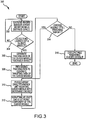
- FIG. 3 representatively illustrates a flowchart in accordance with an exemplary embodiment of the present invention.
- a representative method embodiment of the present invention begins in step 302 with a ground-based sensor array monitoring a defined space for launch of a guided missile.
- ground-based sensor array may monitor the airspace over an airport, sports stadium, power plant, building, and/or the like.
- ground-based sensor array may comprise one or more radar sites actively monitoring the defined space.
- ground-based sensor array may comprise a plurality of IR sensors passively monitoring the defined space for launch of a guided missile.
- ground-based sensor array detects the launch of a guided missile or the intrusion of a guided missile into the defined space being monitored. If no intrusion or launch is detected, the method returns to step 302 ( e.g ., monitoring of the defined space). If a launch or intrusion is detected, the method moves to step 306 where the ground-based sensor array generates tracking data of the guided missile. For example, if ground-based sensor array comprises one or more radar sites, then an actual position and vector of the guided missile may be generated. If ground-based sensor array comprises a plurality of IR sensors, then angular coordinates from each IR sensor may be generated based on the location of each of the plurality of IR sensors.
- the guided missile may be tracking a target in the defined space, such as an aircraft, and/or the like.
- the guided missile may also be targeted on a fixed target such as a building, and/or the like. Tracking data may be communicated to a control node.
- a control node receives tracking data from the ground-based sensor array.
- the control node may process tracking data to generate targeting data of the guided missile.
- Targeting data may comprise a position and/or a vector of the guided missile. For example, upon receiving a plurality of angular coordinates from a plurality of IR sensors, the control node may triangulate the position and vector of the guided missile.
- targeting data is computed, the control node may communicate targeting data to one or more phased array directed-energy units.
- a phased array directed-energy unit radiates the guided missile with microwave radiation suitably focused or spoiled based on the targeting data received from the control node.
- the microwave radiation disrupts at least one electronic component of the guided missile such that the guided missile discontinues tracking the target.
- an electronic component in the sensor system of the guided missile may be disrupted through the introduction of spurious signals, and/or the like, such that the guided missile loses a target lock on its target.
- an electronic component in the guidance system of the guided missile may be disrupted such that the guided missile changes course and diverges from the target.
- phased array directed-energy unit continues radiating the guided missile in step 312 .
- phased array directed-energy.unit may increase or decrease the power level of microwave energy radiating the guided missile to further affect disruption of an electronic component.
- phased array directed-energy unit may alter the modulation and/or carrier frequency of microwave energy irradiating the guided missile to further effect disruption of an electronic component disposed therein.
- phased array directed-energy unit may be configured to discontinue irradiation of the guided missile in step 316 . Determination of whether the guided missile is still tracking the target may include, but is not limited to, evaluating whether the guided missile is no longer airborne or evaluating whether the guided missile is headed in a direction substantially divergent from the target, and/or the like.
- control node may calculate the launch point of the guided missile and alert authorities to both the launch point and the fact that a guided missile is in the air, so that other potential targets in the area may be diverted and/or notified.
- anti-missile system 100 may track and disrupt a guided missile targeted at an asset other than that of an aircraft, such as, for example, a tank, truck, ship, and/or the like.
- anti-missile system 100 may track and disrupt a guided missile targeted on a fixed target, such as a building, bridge, power plant, and/or the like.
- FIG. 4 is a representative graph depicting target location error as a function of range without wave form beam spoiling according to one embodiment of the present invention. As is apparent from the figure, the ability to effectively locate a target by an antimissile system without a defocused beam is greatly diminishes at increased range from the reference point.
- the present invention may be described herein in terms of functional block components, optional selections and various processing steps. It should be appreciated that such functional blocks may be realized by any number of hardware and/or software components configured to perform the specified functions.
- the present invention may employ various integrated circuit components, e.g., memory elements, processing elements, logic elements, matchable data structures, and the like, which may carry out a variety of functions under the control of one or more microprocessors or other control devices.
- the software elements of the present invention may be implemented with any programming or scripting language now known or hereafter derived in the art, with the various algorithms being implemented with any combination of data structures, objects, processes, routines or other programming elements.
- the present invention may employ any number of conventional techniques for data transmission, signaling, data processing, network control, and/or the like. Still further, the invention could be used to detect or prevent security issues with a client-side scripting language and/or the like.
- a suitably configured data network may include any system for exchanging data. Moreover, the system contemplates the use, sale, and/or distribution of any goods, services or information having similar functionality described herein.
- Computing units may be connected with each other via a data communication network. A variety of conventional communications media and protocols may be used for data links.
- the present invention may be embodied as a method, a system, a device, and/or a computer program product. Accordingly, the present invention may take the form of an entirely software embodiment, an entirely hardware embodiment, or an embodiment combining aspects of both software and hardware. Furthermore, the present invention may take the form of a computer program product on a computer-readable storage medium having computer-readable program code means embodied in the storage medium. Any suitable computer-readable storage medium may be utilized, including hard disks, CD-ROM, optical storage devices, magnetic storage devices, and/or the like.
- any databases, systems, or components of the present invention may consist of any combination of databases or components at a single location or at multiple locations, wherein each database or system includes any of various suitable security features, such as firewalls, access codes, encryption, de-encryption, compression, decompression, and/or the like.
Landscapes
- Engineering & Computer Science (AREA)
- Radar, Positioning & Navigation (AREA)
- Remote Sensing (AREA)
- General Engineering & Computer Science (AREA)
- Physics & Mathematics (AREA)
- Electromagnetism (AREA)
- Computer Networks & Wireless Communication (AREA)
- General Physics & Mathematics (AREA)
- Aviation & Aerospace Engineering (AREA)
- Chemical & Material Sciences (AREA)
- Combustion & Propulsion (AREA)
- Radar Systems Or Details Thereof (AREA)
Claims (13)
- Zielbekämpfungssystem, wobei das System Folgendes umfasst:ein Sensormodul (103, 105), das konfiguriert ist, um ein Ziel (108) zu detektieren, wobei das Sensormodul ferner konfiguriert ist, um Zielverfolgungsinformationen bereitzustellen;ein Steuermodul (104), das mit dem Sensormodul gekoppelt ist, wobei das Steuermodul konfiguriert ist, um Zielinformationen in Reaktion auf die Zielverfolgungsinformationen bereitzustellen; undein Modul (106) für gerichtete Energie, das konfiguriert ist, um ein detektiertes Ziel mit einem Mikrowellenstrahlungsbündel in Reaktion auf die Zielinformationen zu bestrahlen, wobei das Strahlenbündel konfiguriert ist, um die Bahn des detektierten Ziels zu beeinflussen;wobei das System dadurch gekennzeichnet ist, dass das Modul für gerichtete Energie ferner konfiguriert ist, um das Mikrowellenstrahlungsbündel in Reaktion auf die Zielinformationen zu beeinträchtigen, wenn eine Entfernung zu dem Ziel abnimmt.
- System nach Anspruch 1, wobei das Sensormodul mehrere Infrarotsensoren (103, 105) umfasst und wobei wenigstens ein Infrarotsensor und wenigstens ein Modul für gerichtete Energie einander zugewiesen sind.
- System nach Anspruch 2, wobei die Zielverfolgungsinformationen durch wenigstens zwei der mehreren Infrarotsensoren bereitgestellt werden.
- System nach Anspruch 1, wobei das Mikrowellenstrahlungsbündel eine Wellenlänge im Bereich von etwa 1 × 10⁻³ Meter bis etwa 3 × 10⁻² Meter enthält.
- System nach Anspruch 1, wobei das Mikrowellenstrahlungsbündel konfiguriert ist, um ein Leitsystem des detektierten Ziels zu beeinflussen.
- System nach Anspruch 1, das ferner wenigstens eine der folgenden Mehrzahlen umfasst:eine Mehrzahl von Sensormodulen;eine Mehrzahl von Steuermodulen; undeine Mehrzahl von Modulen für gerichtete Energie.
- Verfahren zur Zielbekämpfung, wobei das Verfahren den folgenden Schritt umfasst:Konfigurieren eines Moduls für gerichtete Energie, um ein detektiertes Ziel mit einem Mikrowellenstrahlungsbündel (310) in Reaktion auf Zielinformationen (308), die von einem Steuermodul (106) bereitgestellt werden, zu bestrahlen, wobei das Strahlenbündel konfiguriert ist, um die Bahn des detektierten Ziels zu beeinflussen; unddadurch gekennzeichnet, dass es ferner den Schritt des Konfigurierens des Moduls für gerichtete Energie, um das Mikrowellenstrahlungsbündel in Reaktion auf die Zielinformationen zu beeinträchtigen, wenn eine Entfernung zu dem Ziel abnimmt, umfasst.
- Zielbekämpfungsverfahren nach Anspruch 7, das ferner die folgenden Schritte umfasst:ein Sensormodul (103, 105), das wenigstens einen Infrarotsensor (302, 304) enthält, detektiert das Ziel und stellt Verfolgungsinformationen (306) bereit; undein Steuermodul (106) stellt in Reaktion auf die Verfolgungsinformationen die Zielinformationen (308) bereit.
- Zielbekämpfungsverfahren nach Anspruch 8, wobei das Sensormodul mehrere Infrarotsensoren umfasst und wobei wenigstens ein Infrarotsensor und wenigstens ein Modul für gerichtete Energie einander zugewiesen sind.
- Zielbekämpfungsverfahren nach Anspruch 9, wobei die Bahninformationen durch wenigstens zwei der mehreren Infrarotsensoren bereitgestellt werden.
- Zielbekämpfungsverfahren nach einem der Ansprüche 7 bis 10, wobei das Mikrowellenstrahlungsbündel eine Wellenlänge im Bereich von etwa 1 × 10⁻³ Meter bis etwa 3 × 10⁻² Meter enthält.
- Zielbekämpfungsverfahren nach einem der Ansprüche 7 bis 11, wobei das Mikrowellenstrahlungsbündel konfiguriert ist, um ein Leitsystem des Ziels zu beeinflussen.
- Zielbekämpfungsverfahren nach einem der Ansprüche 7 bis 12, das ferner wenigstens eine der folgenden Mehrzahlen umfasst: eine Mehrzahl von Sensormodulen; eine Mehrzahl von Steuermodulen und eine Mehrzahl von Modulen für gerichtete Energie.
Applications Claiming Priority (2)
| Application Number | Priority Date | Filing Date | Title |
|---|---|---|---|
| US11/940,425 US7961133B2 (en) | 2007-11-15 | 2007-11-15 | System and method for diverting a guided missile |
| PCT/US2008/080764 WO2009091424A1 (en) | 2007-11-15 | 2008-10-22 | System and method for diverting a guided missile |
Publications (3)
| Publication Number | Publication Date |
|---|---|
| EP2232296A1 EP2232296A1 (de) | 2010-09-29 |
| EP2232296A4 EP2232296A4 (de) | 2011-06-08 |
| EP2232296B1 true EP2232296B1 (de) | 2012-05-16 |
Family
ID=40885580
Family Applications (1)
| Application Number | Title | Priority Date | Filing Date |
|---|---|---|---|
| EP08871002A Active EP2232296B1 (de) | 2007-11-15 | 2008-10-22 | System und Verfahren zum Ablenken eines Lenkflugkörpers |
Country Status (3)
| Country | Link |
|---|---|
| US (1) | US7961133B2 (de) |
| EP (1) | EP2232296B1 (de) |
| WO (1) | WO2009091424A1 (de) |
Cited By (1)
| Publication number | Priority date | Publication date | Assignee | Title |
|---|---|---|---|---|
| RU2611683C2 (ru) * | 2014-12-12 | 2017-02-28 | Николай Евгеньевич Староверов | Система преодоления противоракетной обороны противника, алгоритм её работы и боеголовка для неё |
Families Citing this family (14)
| Publication number | Priority date | Publication date | Assignee | Title |
|---|---|---|---|---|
| WO2009145904A1 (en) * | 2008-05-29 | 2009-12-03 | Raytheon Company | Target tracking system and method with jitter reduction suitable for directed energy systems |
| WO2010144105A2 (en) * | 2009-02-26 | 2010-12-16 | Raytheon Company | Integrated airport domain awareness response system, system for ground-based transportable defense of airports against manpads, and methods |
| US9830408B1 (en) * | 2012-11-29 | 2017-11-28 | The United States Of America As Represented By The Secretary Of The Army | System and method for evaluating the performance of a weapon system |
| US9605934B1 (en) | 2014-01-30 | 2017-03-28 | Mordechai Shefer | Relaying of missile body roll angle |
| DE102014014117A1 (de) * | 2014-09-24 | 2016-03-24 | Diehl Bgt Defence Gmbh & Co. Kg | Abwehrvorrichtung zum Bekämpfen eines unbemannten Luftfahrzeugs, Schutzeinrichtung zum Bekämpfen eines unbemannten Luftfahrzeugs und Verfahren zum Betrieb einer Schutzeinrichtung |
| US9689976B2 (en) * | 2014-12-19 | 2017-06-27 | Xidrone Systems, Inc. | Deterent for unmanned aerial systems |
| US9715009B1 (en) * | 2014-12-19 | 2017-07-25 | Xidrone Systems, Inc. | Deterent for unmanned aerial systems |
| RU2586882C1 (ru) * | 2015-02-25 | 2016-06-10 | Открытое акционерное общество "Российская корпорация ракетно-космического приборостроения и информационных систем" (ОАО "Российские космические системы") | Способ создания ложных радиолокационных целей и система для его реализации |
| RU2609530C1 (ru) * | 2015-12-23 | 2017-02-02 | Федеральное государственное казённое военное образовательное учреждение высшего профессионального образования "Военная академия воздушно-космической обороны имени Маршала Советского Союза Г.К. Жукова" Министерства обороны Российской Федерации | Способ распознавания направления самонаведения пущенной по группе самолётов ракеты с радиолокационной головкой самонаведения |
| US10473758B2 (en) * | 2016-04-06 | 2019-11-12 | Raytheon Company | Universal coherent technique generator |
| EP3483629B1 (de) * | 2017-11-09 | 2021-12-29 | Veoneer Sweden AB | Detektion einer parkreihe mit einem fahrzeugradarsystem |
| US10907940B1 (en) | 2017-12-12 | 2021-02-02 | Xidrone Systems, Inc. | Deterrent for unmanned aerial systems using data mining and/or machine learning for improved target detection and classification |
| RU2679597C1 (ru) * | 2018-05-25 | 2019-02-12 | Федеральное государственное казённое военное образовательное учреждение высшего образования "Военная академия воздушно-космической обороны имени Маршала Советского Союза Г.К. Жукова" Министерства обороны Российской Федерации | Способ функционирования импульсно-доплеровской бортовой радиолокационной станции при обнаружении воздушной цели - носителя станций радиотехнической разведки и активных помех |
| US11248879B1 (en) * | 2020-06-30 | 2022-02-15 | Bae Systems Information And Electronic System Integration Inc. | Soft kill laser configuration for ground vehicle threats |
Family Cites Families (26)
| Publication number | Priority date | Publication date | Assignee | Title |
|---|---|---|---|---|
| US6707052B1 (en) * | 1963-02-07 | 2004-03-16 | Norman R. Wild | Infrared deception countermeasure system |
| US4456912A (en) * | 1972-04-03 | 1984-06-26 | Harvest Queen Mill & Elevator Company | High energy microwave defense system |
| US4582398A (en) * | 1984-01-20 | 1986-04-15 | The United States Of America As Represented By The Secretary Of The Army | Large continuously focusable gas lenses |
| USH1034H (en) * | 1990-12-28 | 1992-03-03 | United States Of America | Millimeter wave tracking radar antenna with variable azimuth pattern |
| US5198607A (en) * | 1992-02-18 | 1993-03-30 | Trw Inc. | Laser anti-missle defense system |
| US5200753A (en) * | 1992-02-20 | 1993-04-06 | Grumman Aerospace Corporation | Monopulse radar jammer using millimeter wave techniques |
| US5747720A (en) * | 1995-06-01 | 1998-05-05 | Trw Inc. | Tactical laser weapon system for handling munitions |
| US6145784A (en) * | 1997-08-27 | 2000-11-14 | Trw Inc. | Shared aperture dichroic active tracker with background subtraction |
| DE10117007A1 (de) * | 2001-04-04 | 2002-10-17 | Buck Neue Technologien Gmbh | Verfahren und Vorrichtung zum Schutz von mobilen militärischen Einrichtungen |
| US6872960B2 (en) * | 2001-04-18 | 2005-03-29 | Raytheon Company | Robust infrared countermeasure system and method |
| IL145730A0 (en) | 2001-10-01 | 2003-06-24 | Rafael Armament Dev Authority | Improved directional infrared counter measure |
| US6864825B2 (en) | 2002-05-31 | 2005-03-08 | The Boeing Company | Method and apparatus for directing electromagnetic radiation to distant locations |
| US6995660B2 (en) * | 2002-09-26 | 2006-02-07 | Bae Systems Information And Electronic Systems Integration Inc. | Commander's decision aid for combat ground vehicle integrated defensive aid suites |
| US6782790B2 (en) * | 2002-12-20 | 2004-08-31 | Bae Systems Information And Electronic Systems Integration Inc. | Method for deflecting fast projectiles |
| US6977598B2 (en) * | 2003-03-07 | 2005-12-20 | Lockheed Martin Corporation | Aircraft protection system and method |
| ATE487953T1 (de) * | 2003-06-04 | 2010-11-15 | Elop Electrooptics Ind Ltd | Faserlasergestütztes störsendesystem |
| DE10349869A1 (de) * | 2003-10-25 | 2005-06-16 | Eads Deutschland Gmbh | System und Verfahren zum Schutz von Transportmitteln gegen IR-gelenkte Flugkörper |
| US6906659B1 (en) * | 2003-12-19 | 2005-06-14 | Tom Ramstack | System for administering a restricted flight zone using radar and lasers |
| US8339580B2 (en) * | 2004-06-30 | 2012-12-25 | Lawrence Livermore National Security, Llc | Sensor-guided threat countermeasure system |
| US7282727B2 (en) * | 2004-07-26 | 2007-10-16 | Retsky Michael W | Electron beam directed energy device and methods of using same |
| US7212148B1 (en) | 2005-04-05 | 2007-05-01 | Itt Manufacturing Enterprises, Inc. | Apparatus for jamming infrared attack unit using a modulated radio frequency carrier |
| US7378626B2 (en) * | 2005-10-04 | 2008-05-27 | Raytheon Company | Directed infrared countermeasures (DIRCM) system and method |
| WO2007059508A1 (en) | 2005-11-15 | 2007-05-24 | University Of Florida Research Foundation, Inc. | Time reversal antenna network based directed energy systems |
| US7504982B2 (en) * | 2005-12-06 | 2009-03-17 | Raytheon Company | Anti-Missile system and method |
| US20090201206A1 (en) * | 2006-04-27 | 2009-08-13 | University Of Florida Research Foundation, Inc. | Method and system for flexible beampattern design using waveform diversity |
| US7865152B2 (en) * | 2007-10-19 | 2011-01-04 | Raytheon Company | RF waveform modulation apparatus and method |
-
2007
- 2007-11-15 US US11/940,425 patent/US7961133B2/en active Active
-
2008
- 2008-10-22 WO PCT/US2008/080764 patent/WO2009091424A1/en not_active Ceased
- 2008-10-22 EP EP08871002A patent/EP2232296B1/de active Active
Cited By (1)
| Publication number | Priority date | Publication date | Assignee | Title |
|---|---|---|---|---|
| RU2611683C2 (ru) * | 2014-12-12 | 2017-02-28 | Николай Евгеньевич Староверов | Система преодоления противоракетной обороны противника, алгоритм её работы и боеголовка для неё |
Also Published As
| Publication number | Publication date |
|---|---|
| US20100283657A1 (en) | 2010-11-11 |
| US7961133B2 (en) | 2011-06-14 |
| EP2232296A4 (de) | 2011-06-08 |
| WO2009091424A1 (en) | 2009-07-23 |
| EP2232296A1 (de) | 2010-09-29 |
Similar Documents
| Publication | Publication Date | Title |
|---|---|---|
| EP2232296B1 (de) | System und Verfahren zum Ablenken eines Lenkflugkörpers | |
| US7504982B2 (en) | Anti-Missile system and method | |
| EP2527865B1 (de) | System, Vorrichtung und Verfahren zum Schützen von Flugzeugen vor eingehenden Raketen und Bedrohungen | |
| Neri | Introduction to electronic defense systems | |
| US7865152B2 (en) | RF waveform modulation apparatus and method | |
| US12104881B2 (en) | Countermeasure system having a confirmation device and method thereof | |
| Balajti et al. | Increased importance of VHF radars in ground-based air defense | |
| Čisar et al. | Principles of anti-drone defense | |
| US7212148B1 (en) | Apparatus for jamming infrared attack unit using a modulated radio frequency carrier | |
| CA2385635A1 (en) | Apparatus and method for providing a deception trackless and response system | |
| Jin et al. | Adaptive beam control considering location inaccuracy for anti-UAV systems | |
| US11662183B1 (en) | Systems and methods for automomous protection of satellites from hostile orbital attackers | |
| KR102420112B1 (ko) | 불법 무인 비행체에 대한 crpa 무력화 장치 및 방법 | |
| Zhou et al. | Performance evaluation of radar and decoy system counteracting antiradiation missile | |
| Zhang et al. | The development of radar and radar countermeasure | |
| AU2020386840B2 (en) | Beam spoiling | |
| Giare et al. | Air and missile defense: Defining the future | |
| Wang et al. | Research on methods to enhance the survivability of AWACS with FDA against anti‐ARMs on a battlefield | |
| RU2850455C1 (ru) | Способ защиты радиолокационной станции от воздействия атакующих боеприпасов | |
| Tang et al. | System Design of Radar Active Jamming | |
| Sankowski et al. | Multifunction C-band radar development in Poland: Electronically scanned array technology | |
| He et al. | A review of research progress in laser jamming and antijamming technology | |
| Gowd | Defending space assets | |
| Castrillo et al. | A Review of Counter-UAS Technologies for Cooperative Defensive Teams of Drones. Drones 2022, 6, 65 | |
| Zhang et al. | Unified Jamming Equation and “One-to-Many Systems” Jammer |
Legal Events
| Date | Code | Title | Description |
|---|---|---|---|
| PUAI | Public reference made under article 153(3) epc to a published international application that has entered the european phase |
Free format text: ORIGINAL CODE: 0009012 |
|
| 17P | Request for examination filed |
Effective date: 20100527 |
|
| AK | Designated contracting states |
Kind code of ref document: A1 Designated state(s): AT BE BG CH CY CZ DE DK EE ES FI FR GB GR HR HU IE IS IT LI LT LU LV MC MT NL NO PL PT RO SE SI SK TR |
|
| AX | Request for extension of the european patent |
Extension state: AL BA MK RS |
|
| DAX | Request for extension of the european patent (deleted) | ||
| A4 | Supplementary search report drawn up and despatched |
Effective date: 20110510 |
|
| RIC1 | Information provided on ipc code assigned before grant |
Ipc: F41G 7/22 20060101ALI20110503BHEP Ipc: G01S 13/00 20060101AFI20090813BHEP |
|
| REG | Reference to a national code |
Ref country code: DE Ref legal event code: R079 Ref document number: 602008015765 Country of ref document: DE Free format text: PREVIOUS MAIN CLASS: G01S0013000000 Ipc: F41H0011020000 |
|
| GRAP | Despatch of communication of intention to grant a patent |
Free format text: ORIGINAL CODE: EPIDOSNIGR1 |
|
| RIC1 | Information provided on ipc code assigned before grant |
Ipc: G01S 13/88 20060101ALI20111118BHEP Ipc: F41H 13/00 20060101ALI20111118BHEP Ipc: F41H 11/02 20060101AFI20111118BHEP Ipc: F41G 7/22 20060101ALI20111118BHEP |
|
| GRAS | Grant fee paid |
Free format text: ORIGINAL CODE: EPIDOSNIGR3 |
|
| GRAA | (expected) grant |
Free format text: ORIGINAL CODE: 0009210 |
|
| AK | Designated contracting states |
Kind code of ref document: B1 Designated state(s): AT BE BG CH CY CZ DE DK EE ES FI FR GB GR HR HU IE IS IT LI LT LU LV MC MT NL NO PL PT RO SE SI SK TR |
|
| REG | Reference to a national code |
Ref country code: GB Ref legal event code: FG4D |
|
| REG | Reference to a national code |
Ref country code: CH Ref legal event code: EP |
|
| REG | Reference to a national code |
Ref country code: AT Ref legal event code: REF Ref document number: 558292 Country of ref document: AT Kind code of ref document: T Effective date: 20120615 |
|
| REG | Reference to a national code |
Ref country code: IE Ref legal event code: FG4D |
|
| REG | Reference to a national code |
Ref country code: DE Ref legal event code: R096 Ref document number: 602008015765 Country of ref document: DE Effective date: 20120712 |
|
| REG | Reference to a national code |
Ref country code: NL Ref legal event code: VDEP Effective date: 20120516 |
|
| REG | Reference to a national code |
Ref country code: LT Ref legal event code: MG4D Effective date: 20120516 |
|
| PG25 | Lapsed in a contracting state [announced via postgrant information from national office to epo] |
Ref country code: FI Free format text: LAPSE BECAUSE OF FAILURE TO SUBMIT A TRANSLATION OF THE DESCRIPTION OR TO PAY THE FEE WITHIN THE PRESCRIBED TIME-LIMIT Effective date: 20120516 Ref country code: IS Free format text: LAPSE BECAUSE OF FAILURE TO SUBMIT A TRANSLATION OF THE DESCRIPTION OR TO PAY THE FEE WITHIN THE PRESCRIBED TIME-LIMIT Effective date: 20120916 Ref country code: LT Free format text: LAPSE BECAUSE OF FAILURE TO SUBMIT A TRANSLATION OF THE DESCRIPTION OR TO PAY THE FEE WITHIN THE PRESCRIBED TIME-LIMIT Effective date: 20120516 Ref country code: NO Free format text: LAPSE BECAUSE OF FAILURE TO SUBMIT A TRANSLATION OF THE DESCRIPTION OR TO PAY THE FEE WITHIN THE PRESCRIBED TIME-LIMIT Effective date: 20120816 Ref country code: CY Free format text: LAPSE BECAUSE OF FAILURE TO SUBMIT A TRANSLATION OF THE DESCRIPTION OR TO PAY THE FEE WITHIN THE PRESCRIBED TIME-LIMIT Effective date: 20120516 Ref country code: PL Free format text: LAPSE BECAUSE OF FAILURE TO SUBMIT A TRANSLATION OF THE DESCRIPTION OR TO PAY THE FEE WITHIN THE PRESCRIBED TIME-LIMIT Effective date: 20120516 Ref country code: SE Free format text: LAPSE BECAUSE OF FAILURE TO SUBMIT A TRANSLATION OF THE DESCRIPTION OR TO PAY THE FEE WITHIN THE PRESCRIBED TIME-LIMIT Effective date: 20120516 |
|
| REG | Reference to a national code |
Ref country code: AT Ref legal event code: MK05 Ref document number: 558292 Country of ref document: AT Kind code of ref document: T Effective date: 20120516 |
|
| PG25 | Lapsed in a contracting state [announced via postgrant information from national office to epo] |
Ref country code: HR Free format text: LAPSE BECAUSE OF FAILURE TO SUBMIT A TRANSLATION OF THE DESCRIPTION OR TO PAY THE FEE WITHIN THE PRESCRIBED TIME-LIMIT Effective date: 20120516 Ref country code: SI Free format text: LAPSE BECAUSE OF FAILURE TO SUBMIT A TRANSLATION OF THE DESCRIPTION OR TO PAY THE FEE WITHIN THE PRESCRIBED TIME-LIMIT Effective date: 20120516 Ref country code: LV Free format text: LAPSE BECAUSE OF FAILURE TO SUBMIT A TRANSLATION OF THE DESCRIPTION OR TO PAY THE FEE WITHIN THE PRESCRIBED TIME-LIMIT Effective date: 20120516 Ref country code: PT Free format text: LAPSE BECAUSE OF FAILURE TO SUBMIT A TRANSLATION OF THE DESCRIPTION OR TO PAY THE FEE WITHIN THE PRESCRIBED TIME-LIMIT Effective date: 20120917 Ref country code: GR Free format text: LAPSE BECAUSE OF FAILURE TO SUBMIT A TRANSLATION OF THE DESCRIPTION OR TO PAY THE FEE WITHIN THE PRESCRIBED TIME-LIMIT Effective date: 20120817 |
|
| PG25 | Lapsed in a contracting state [announced via postgrant information from national office to epo] |
Ref country code: BE Free format text: LAPSE BECAUSE OF FAILURE TO SUBMIT A TRANSLATION OF THE DESCRIPTION OR TO PAY THE FEE WITHIN THE PRESCRIBED TIME-LIMIT Effective date: 20120516 |
|
| PG25 | Lapsed in a contracting state [announced via postgrant information from national office to epo] |
Ref country code: DK Free format text: LAPSE BECAUSE OF FAILURE TO SUBMIT A TRANSLATION OF THE DESCRIPTION OR TO PAY THE FEE WITHIN THE PRESCRIBED TIME-LIMIT Effective date: 20120516 Ref country code: CZ Free format text: LAPSE BECAUSE OF FAILURE TO SUBMIT A TRANSLATION OF THE DESCRIPTION OR TO PAY THE FEE WITHIN THE PRESCRIBED TIME-LIMIT Effective date: 20120516 Ref country code: AT Free format text: LAPSE BECAUSE OF FAILURE TO SUBMIT A TRANSLATION OF THE DESCRIPTION OR TO PAY THE FEE WITHIN THE PRESCRIBED TIME-LIMIT Effective date: 20120516 Ref country code: EE Free format text: LAPSE BECAUSE OF FAILURE TO SUBMIT A TRANSLATION OF THE DESCRIPTION OR TO PAY THE FEE WITHIN THE PRESCRIBED TIME-LIMIT Effective date: 20120516 Ref country code: NL Free format text: LAPSE BECAUSE OF FAILURE TO SUBMIT A TRANSLATION OF THE DESCRIPTION OR TO PAY THE FEE WITHIN THE PRESCRIBED TIME-LIMIT Effective date: 20120516 Ref country code: RO Free format text: LAPSE BECAUSE OF FAILURE TO SUBMIT A TRANSLATION OF THE DESCRIPTION OR TO PAY THE FEE WITHIN THE PRESCRIBED TIME-LIMIT Effective date: 20120516 Ref country code: SK Free format text: LAPSE BECAUSE OF FAILURE TO SUBMIT A TRANSLATION OF THE DESCRIPTION OR TO PAY THE FEE WITHIN THE PRESCRIBED TIME-LIMIT Effective date: 20120516 |
|
| PG25 | Lapsed in a contracting state [announced via postgrant information from national office to epo] |
Ref country code: IT Free format text: LAPSE BECAUSE OF FAILURE TO SUBMIT A TRANSLATION OF THE DESCRIPTION OR TO PAY THE FEE WITHIN THE PRESCRIBED TIME-LIMIT Effective date: 20120516 |
|
| PLBE | No opposition filed within time limit |
Free format text: ORIGINAL CODE: 0009261 |
|
| STAA | Information on the status of an ep patent application or granted ep patent |
Free format text: STATUS: NO OPPOSITION FILED WITHIN TIME LIMIT |
|
| 26N | No opposition filed |
Effective date: 20130219 |
|
| PG25 | Lapsed in a contracting state [announced via postgrant information from national office to epo] |
Ref country code: ES Free format text: LAPSE BECAUSE OF FAILURE TO SUBMIT A TRANSLATION OF THE DESCRIPTION OR TO PAY THE FEE WITHIN THE PRESCRIBED TIME-LIMIT Effective date: 20120827 |
|
| PG25 | Lapsed in a contracting state [announced via postgrant information from national office to epo] |
Ref country code: MC Free format text: LAPSE BECAUSE OF NON-PAYMENT OF DUE FEES Effective date: 20121031 |
|
| REG | Reference to a national code |
Ref country code: CH Ref legal event code: PL |
|
| REG | Reference to a national code |
Ref country code: DE Ref legal event code: R097 Ref document number: 602008015765 Country of ref document: DE Effective date: 20130219 |
|
| REG | Reference to a national code |
Ref country code: IE Ref legal event code: MM4A |
|
| PG25 | Lapsed in a contracting state [announced via postgrant information from national office to epo] |
Ref country code: BG Free format text: LAPSE BECAUSE OF FAILURE TO SUBMIT A TRANSLATION OF THE DESCRIPTION OR TO PAY THE FEE WITHIN THE PRESCRIBED TIME-LIMIT Effective date: 20120816 Ref country code: LI Free format text: LAPSE BECAUSE OF NON-PAYMENT OF DUE FEES Effective date: 20121031 Ref country code: IE Free format text: LAPSE BECAUSE OF NON-PAYMENT OF DUE FEES Effective date: 20121022 Ref country code: CH Free format text: LAPSE BECAUSE OF NON-PAYMENT OF DUE FEES Effective date: 20121031 |
|
| PG25 | Lapsed in a contracting state [announced via postgrant information from national office to epo] |
Ref country code: MT Free format text: LAPSE BECAUSE OF FAILURE TO SUBMIT A TRANSLATION OF THE DESCRIPTION OR TO PAY THE FEE WITHIN THE PRESCRIBED TIME-LIMIT Effective date: 20120516 |
|
| PG25 | Lapsed in a contracting state [announced via postgrant information from national office to epo] |
Ref country code: TR Free format text: LAPSE BECAUSE OF FAILURE TO SUBMIT A TRANSLATION OF THE DESCRIPTION OR TO PAY THE FEE WITHIN THE PRESCRIBED TIME-LIMIT Effective date: 20120516 |
|
| PG25 | Lapsed in a contracting state [announced via postgrant information from national office to epo] |
Ref country code: LU Free format text: LAPSE BECAUSE OF NON-PAYMENT OF DUE FEES Effective date: 20121022 |
|
| PG25 | Lapsed in a contracting state [announced via postgrant information from national office to epo] |
Ref country code: HU Free format text: LAPSE BECAUSE OF FAILURE TO SUBMIT A TRANSLATION OF THE DESCRIPTION OR TO PAY THE FEE WITHIN THE PRESCRIBED TIME-LIMIT Effective date: 20081022 |
|
| REG | Reference to a national code |
Ref country code: FR Ref legal event code: PLFP Year of fee payment: 9 |
|
| REG | Reference to a national code |
Ref country code: FR Ref legal event code: PLFP Year of fee payment: 10 |
|
| REG | Reference to a national code |
Ref country code: FR Ref legal event code: PLFP Year of fee payment: 11 |
|
| P01 | Opt-out of the competence of the unified patent court (upc) registered |
Effective date: 20230530 |
|
| PGFP | Annual fee paid to national office [announced via postgrant information from national office to epo] |
Ref country code: GB Payment date: 20250923 Year of fee payment: 18 |
|
| PGFP | Annual fee paid to national office [announced via postgrant information from national office to epo] |
Ref country code: FR Payment date: 20250925 Year of fee payment: 18 |
|
| PGFP | Annual fee paid to national office [announced via postgrant information from national office to epo] |
Ref country code: DE Payment date: 20250923 Year of fee payment: 18 |