EP2232094B1 - Damping-adjustable shock-absorber with a double-front-sealed device for connection between an intermediate tube and a control valve - Google Patents
Damping-adjustable shock-absorber with a double-front-sealed device for connection between an intermediate tube and a control valve Download PDFInfo
- Publication number
- EP2232094B1 EP2232094B1 EP08865805A EP08865805A EP2232094B1 EP 2232094 B1 EP2232094 B1 EP 2232094B1 EP 08865805 A EP08865805 A EP 08865805A EP 08865805 A EP08865805 A EP 08865805A EP 2232094 B1 EP2232094 B1 EP 2232094B1
- Authority
- EP
- European Patent Office
- Prior art keywords
- control valve
- intermediate tube
- shock
- tube
- spacer body
- Prior art date
- Legal status (The legal status is an assumption and is not a legal conclusion. Google has not performed a legal analysis and makes no representation as to the accuracy of the status listed.)
- Active
Links
- 239000006096 absorbing agent Substances 0.000 title claims abstract description 24
- 238000007789 sealing Methods 0.000 claims abstract description 21
- 125000006850 spacer group Chemical group 0.000 claims abstract description 21
- 238000013016 damping Methods 0.000 claims abstract description 8
- 239000012530 fluid Substances 0.000 claims abstract description 8
- 239000013536 elastomeric material Substances 0.000 claims description 5
- 239000002184 metal Substances 0.000 claims description 4
- 230000003014 reinforcing effect Effects 0.000 claims 1
- 239000000725 suspension Substances 0.000 description 3
- 230000005540 biological transmission Effects 0.000 description 1
- 238000004519 manufacturing process Methods 0.000 description 1
- 230000035939 shock Effects 0.000 description 1
- 238000003466 welding Methods 0.000 description 1
Images

Classifications
-
- F—MECHANICAL ENGINEERING; LIGHTING; HEATING; WEAPONS; BLASTING
- F16—ENGINEERING ELEMENTS AND UNITS; GENERAL MEASURES FOR PRODUCING AND MAINTAINING EFFECTIVE FUNCTIONING OF MACHINES OR INSTALLATIONS; THERMAL INSULATION IN GENERAL
- F16F—SPRINGS; SHOCK-ABSORBERS; MEANS FOR DAMPING VIBRATION
- F16F9/00—Springs, vibration-dampers, shock-absorbers, or similarly-constructed movement-dampers using a fluid or the equivalent as damping medium
- F16F9/32—Details
- F16F9/36—Special sealings, including sealings or guides for piston-rods
- F16F9/369—Sealings for elements other than pistons or piston rods, e.g. valves
-
- F—MECHANICAL ENGINEERING; LIGHTING; HEATING; WEAPONS; BLASTING
- F16—ENGINEERING ELEMENTS AND UNITS; GENERAL MEASURES FOR PRODUCING AND MAINTAINING EFFECTIVE FUNCTIONING OF MACHINES OR INSTALLATIONS; THERMAL INSULATION IN GENERAL
- F16F—SPRINGS; SHOCK-ABSORBERS; MEANS FOR DAMPING VIBRATION
- F16F9/00—Springs, vibration-dampers, shock-absorbers, or similarly-constructed movement-dampers using a fluid or the equivalent as damping medium
- F16F9/32—Details
- F16F9/3207—Constructional features
- F16F9/3235—Constructional features of cylinders
- F16F9/325—Constructional features of cylinders for attachment of valve units
Definitions
- the present invention relates in general to a damping-adjustable shock-absorber intended to be used for instance in an active or semi-active suspension system of a motor vehicle, and more in particular to a sealed connection device between an intermediate tube and a control valve of the shock-absorber.
- a typical damping-adjustable shock-absorber comprises:
- a further sealed connection arrangement between the intermediate tube and the control valve of a damping-adjustable shock-absorber is known from Us Patent US6035979 .
- the intermediate tube has a connection opening in which a fitting collar for the control valve is secured by caulking.
- An O-ring ensuring a sealed connection between the valve and the intermediate tube is radially (wherein the terms "radial” and “axial” are to be intended, in the following description and claims, as referred to the axis of the control valve, that is to say, to an axis extending perpendicularly to the axis of the shock-absorber) interposed between the fitting collar and an attachment portion of the control valve.
- connection between the intermediate tube and the control valve involves a single radial sealing member consisting in both cases in an O-ring.
- the invention is based on the idea of providing a sealed connection device between the intermediate tube and the control valve comprising:
- a damping adjustable shock-absorber according to the invention is capable of ensuring a correct oil flow, and accordingly a correct pressure transmission, between the intermediate tube and the control valve. Moreover, a damping-adjustable shock-absorber according to the invention has a more compact structure, is easier to assemble and has a lower manufacturing cost than the prior art discussed above.
- a damping-adjustable shock-absorber intended to be used in particular in an active or semi-active suspension system for a motor vehicle is generally indicated 10 and comprises, in per-se-known manner:
- the control valve 28 is secured to the outer tube 20 so as to extend substantially perpendicularly to the axis of the outer tube, that is to say, perpendicularly to the axis of the shock-absorber.
- the valve 28 is threaded into an internally threaded tubular attachment element 30 which is in turn rigidly connected, for instance by welding, to the outer tube 20.
- control valve 28 has an inlet 32 in fluid communication with the by-pass chamber 22 through an opening 34 formed in the intermediate tube 22.
- a sealed connection device 36 is axially interposed between the intermediate tube 22 and the control valve 28 at the opening 34 to allow the damping fluid to flow without leakage from the by-pass chamber 24 to the inlet 32 of the control valve 28 and vice versa.
- the sealed connection device 36 is configured so as to form a double front seal, on the one hand with the intermediate tube 22 and on the other hand with a valve body 38 of the control valve 28.
- the sealed connection device 36 comprises a spacer body 40 forming a radially inner tubular portion 42 which at a first end (upper end, when seen by the observer of Figure 2 ) is in abutment against a front face 44 of the valve body 38 and at the opposite end (lower end, when seen form the observer of Figure 2 ) projects into the by-pass chamber 24 of the intermediate tube 22 through the opening 34, and a radial flange portion 46 which extends radially from the tubular portion 42 and is in abutment at its opposite axial ends against the front face 44 of the valve body 38 and against the outer cylindrical surface of the intermediate tube 22.
- the sealed connection device 36 further comprises a first front sealing member 48, which is formed in this case as an O-ring and is received in a first toroidal groove 50 provided on a first axial face 52 (upper face, when seen by the observer of Figure 2 ) of the flange portion 46 of the spacer body 40 so as to seal against the front face 44 of the valve body 38, and a second front sealing member 54, which is formed in this case as an O-ring as well and is received in a second toroidal groove 56 provided on a second axial face 58 (lower face, when seen by the observer of Figure 2 ) of the flange portion 46 of the spacer body 40 so as to seal against the outer cylindrical surface of the intermediate tube 22.
- the spacer body 40 is formed as a single piece of metal, while the two O-rings 48 and 54 are made of elastomeric material.
- the sealed connection device 36 of Figure 3 comprises a spacer body 40, a first front sealing member 48 in contact with the front face 44 of the valve body 38 and a second front sealing member 54 in contact with the outer cylindrical surface of the intermediate tube 22.
- the spacer body 40 is made of elastomeric material, internally reinforced by a metal core 60, and forms integrally the two front sealing members 48 and 54.
- first front sealing member 48 is formed on a first axial face 52 (upper face, when seen by the observer of Figure 3 ) of the spacer body 40, while the second front sealing member 54 is formed on an opposite axial face 58 (lower face, when seen by the observer of Figure 3 ).
- the spacer body 40 also forms a radially inner tubular portion 42 which projects partially into the by-pass chamber 24 of the intermediate tube 22 through the opening 34.
- FIG. 4 A further variant of embodiment of the sealed connection device according to the invention is illustrated in Figure 4 , where parts and elements identical or corresponding to those of Figures 2 and 3 have been given the same reference numerals.
- the spacer body 40 is simply a ring arranged around the opening 34 of the intermediate tube 22 in contact with a first axial face 52 thereof against the front face 44 of the valve body 38 and with an opposite axial face 58 thereof against the outer cylindrical surface of the intermediate tube itself.
- the first and second front sealing members 48 and 54 are formed in this case by a single piece of elastomeric material of annular shape which is secured to the inner cylindrical surface of the spacer body 40.
Abstract
Description
- The present invention relates in general to a damping-adjustable shock-absorber intended to be used for instance in an active or semi-active suspension system of a motor vehicle, and more in particular to a sealed connection device between an intermediate tube and a control valve of the shock-absorber.
- Nowadays, there is a wider and wider use, particularly in the motor-vehicle field, of damping-adjustable shock-absorbers which are capable of varying their damping characteristics under control of an electronic control unit to change the behaviour of the suspension system of the vehicle depending for instance on the conditions of the road surface and on the running conditions of the vehicle. A typical damping-adjustable shock-absorber comprises:
- a pressure tube enclosing a pressure chamber in which a damping fluid (oil) is contained;
- a piston slidably mounted within the pressure chamber of the pressure tube so as to split it into a lower pressure chamber and an upper pressure chamber;
- an outer tube;
- an intermediate tube which is fitted onto the pressure tube and encloses a by-pass chamber communicating with the upper pressure chamber through communication holes provided in the pressure tube; and
- a control valve, typically a solenoid valve, which is connected to the intermediate tube and is arranged to control the flow of the fluid between the pressure chamber and the by-pass chamber.
- International Patent application
WO2005/036013 discloses a damping-adjustable shock-absorber comprising: - a collar which is secured to the intermediate tube and forms a base portion extending parallel to the intermediate tube and a tubular portion extending perpendicularly to the intermediate tube;
- a control valve having a valve seat which in the assembled condition is received within the collar; and
- an O-ring arranged in a circumferential groove of the valve seat so as to be kept in contact against the tubular portion of the collar to ensure a sealed connection between the control valve and the intermediate tube.
- A further sealed connection arrangement between the intermediate tube and the control valve of a damping-adjustable shock-absorber is known from Us Patent
US6035979 . According to this prior art document, the intermediate tube has a connection opening in which a fitting collar for the control valve is secured by caulking. An O-ring ensuring a sealed connection between the valve and the intermediate tube is radially (wherein the terms "radial" and "axial" are to be intended, in the following description and claims, as referred to the axis of the control valve, that is to say, to an axis extending perpendicularly to the axis of the shock-absorber) interposed between the fitting collar and an attachment portion of the control valve. - In both the above-mentioned arrangements, the connection between the intermediate tube and the control valve involves a single radial sealing member consisting in both cases in an O-ring.
- It is therefore an object of the present invention to provide a damping-adjustable shock absorber having a sealed connection device between the intermediate tube and the control valve which has a more compact structure, which can be assembled in an easier way and which can be manufactured at a lower cost than the prior art discussed above.
- This and other objects are fully achieved according to the invention by virtue of a damping-adjustable shock-absorber having the characteristics defined in the enclosed claim 1.
- In short, the invention is based on the idea of providing a sealed connection device between the intermediate tube and the control valve comprising:
- a spacer body axially interposed between the intermediate tube and the control valve;
- a first front sealing member in contact with a front face of the control valve; and
- a second front sealing member in contact with the outer cylindrical surface of the intermediate tube.
- By virtue of the fact that the two front sealing members provided between the intermediate tube and the control valve form a double front seal, a damping adjustable shock-absorber according to the invention is capable of ensuring a correct oil flow, and accordingly a correct pressure transmission, between the intermediate tube and the control valve. Moreover, a damping-adjustable shock-absorber according to the invention has a more compact structure, is easier to assemble and has a lower manufacturing cost than the prior art discussed above.
- Further characteristics and advantages of the invention will become more evident from the following detailed description, given purely by way of non-limiting example with reference to the appended drawings, in which:
-
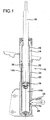
Figure 1 is an axial section view of a damping-adjustable shock-absorber provided with a sealed connection device between the intermediate tube and the control valve according to a first preferred embodiment of the invention; -
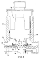
Figure 2 is an axial section view on an enlarged scale showing in detail the sealed connection device ofFigure 1 ; -
Figure 3 is an axial section view on an enlarged scale showing in detail a variant of embodiment of the sealed connection device between the intermediate tube and the control valve; and -
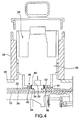
Figure 4 is an axial section view on an enlarged scale showing in detail a further variant of embodiment of the sealed connection device between the intermediate tube and the control valve. - With reference first to
Figure 1 , a damping-adjustable shock-absorber intended to be used in particular in an active or semi-active suspension system for a motor vehicle is generally indicated 10 and comprises, in per-se-known manner: - a
pressure tube 12 enclosing apressure chamber 14 in which a damping fluid, typically oil, is contained; - a
plunger 16 slidably mounted within thepressure chamber 14 of thepressure tube 12 so as to split it into alower pressure chamber 14a and anupper pressure chamber 14b; - a
rod 18 which carries at an end thereof the plunger16 and projects at the opposite end from thepressure tube 12; - an
outer tube 20; - an
intermediate tube 22 which is fitted onto thepressure tube 12 and encloses a by-pass chamber 24 communicating with theupper pressure chamber 14b throughcommunication holes 26 provided in thepressure tube 12; and - a
control valve 28, typically a solenoid valve, which is connected to theintermediate tube 22 and is arranged to control the flow of the damping fluid between thepressure chamber 14 and the by-pass chamber 24. - The
control valve 28 is secured to theouter tube 20 so as to extend substantially perpendicularly to the axis of the outer tube, that is to say, perpendicularly to the axis of the shock-absorber. In particular, in the proposed embodiments thevalve 28 is threaded into an internally threadedtubular attachment element 30 which is in turn rigidly connected, for instance by welding, to theouter tube 20. - With reference in particular to
Figures 2 to 4 , thecontrol valve 28 has aninlet 32 in fluid communication with the by-pass chamber 22 through anopening 34 formed in theintermediate tube 22. - A sealed
connection device 36 is axially interposed between theintermediate tube 22 and thecontrol valve 28 at theopening 34 to allow the damping fluid to flow without leakage from the by-pass chamber 24 to theinlet 32 of thecontrol valve 28 and vice versa. As will be explained in detail here below, the sealedconnection device 36 is configured so as to form a double front seal, on the one hand with theintermediate tube 22 and on the other hand with avalve body 38 of thecontrol valve 28. - In the embodiment of
Figure 2 , the sealedconnection device 36 comprises aspacer body 40 forming a radially innertubular portion 42 which at a first end (upper end, when seen by the observer ofFigure 2 ) is in abutment against afront face 44 of thevalve body 38 and at the opposite end (lower end, when seen form the observer ofFigure 2 ) projects into the by-pass chamber 24 of theintermediate tube 22 through theopening 34, and aradial flange portion 46 which extends radially from thetubular portion 42 and is in abutment at its opposite axial ends against thefront face 44 of thevalve body 38 and against the outer cylindrical surface of theintermediate tube 22. The sealedconnection device 36 further comprises a firstfront sealing member 48, which is formed in this case as an O-ring and is received in a firsttoroidal groove 50 provided on a first axial face 52 (upper face, when seen by the observer ofFigure 2 ) of theflange portion 46 of thespacer body 40 so as to seal against thefront face 44 of thevalve body 38, and a secondfront sealing member 54, which is formed in this case as an O-ring as well and is received in a secondtoroidal groove 56 provided on a second axial face 58 (lower face, when seen by the observer ofFigure 2 ) of theflange portion 46 of thespacer body 40 so as to seal against the outer cylindrical surface of theintermediate tube 22. Preferably, thespacer body 40 is formed as a single piece of metal, while the two O-rings - A variant of embodiment of the sealed connection device according to the invention is illustrated in
Figure 3 , where parts and elements identical or corresponding to those ofFigure 2 have been given the same reference numerals. Also the sealedconnection device 36 ofFigure 3 comprises aspacer body 40, a firstfront sealing member 48 in contact with thefront face 44 of thevalve body 38 and a secondfront sealing member 54 in contact with the outer cylindrical surface of theintermediate tube 22. In this case, thespacer body 40 is made of elastomeric material, internally reinforced by ametal core 60, and forms integrally the twofront sealing members front sealing member 48 is formed on a first axial face 52 (upper face, when seen by the observer ofFigure 3 ) of thespacer body 40, while the secondfront sealing member 54 is formed on an opposite axial face 58 (lower face, when seen by the observer ofFigure 3 ). As in the embodiment ofFigure 2 , thespacer body 40 also forms a radially innertubular portion 42 which projects partially into the by-pass chamber 24 of theintermediate tube 22 through theopening 34. - A further variant of embodiment of the sealed connection device according to the invention is illustrated in
Figure 4 , where parts and elements identical or corresponding to those ofFigures 2 and3 have been given the same reference numerals. In this case, thespacer body 40 is simply a ring arranged around the opening 34 of theintermediate tube 22 in contact with a firstaxial face 52 thereof against thefront face 44 of thevalve body 38 and with an oppositeaxial face 58 thereof against the outer cylindrical surface of the intermediate tube itself. The first and secondfront sealing members spacer body 40. - Naturally, the principle of the invention remaining unchanged, the embodiments and constructional details may vary widely with respect to those described and illustrated purely by way of non-limiting example.
Claims (8)
- Damping-adjustable shock-absorber (10) comprising a pressure tube (12), an outer tube (20), an intermediate tube fitted onto the pressure tube (12), a control valve (28) for controlling the flow of a damping fluid to/from the intermediate tube (22) and a sealed connection device (36) for sealed connection of the control valve (28) with the intermediate tube (22),
characterized in that the sealed connection device (36) comprises a spacer body (40) axially interposed between the intermediate tube (22) and the control valve (28), a first front sealing member (48) in contact with a front face (44) of the control valve (28), and a second front sealing member (54) in contact with the outer cylindrical surface of the intermediate tube (22). - Shock-absorber according to claim 1, wherein the first front sealing member (48) is formed by an O-ring received in a first toroidal groove (50) provided on a first axial face (52) of the spacer body (40) in contact with a front face (44) of a valve body (38) of the control valve (28).
- Shock-absorber according to claim 1 or claim 2, wherein the second front sealing member (54) is formed by an O-ring received in a second toroidal groove (56) provided on a second axial face (58) of the spacer body (40) in contact with the outer cylindrical surface of the intermediate tube (22).
- Shock-absorber according to claim 2 or clam 3, wherein the spacer body (40) is formed as a single piece of metal.
- Shock-absorber according to claim 1, wherein the spacer body (40) is made of elastomeric material and forms integrally the first and second front sealing members (48, 54).
- Shock-absorber according to claim 5, wherein the first and second front sealing members (48, 54) are formed on first and second axial faces (52, 58) of the spacer body (40), respectively.
- Shock-absorber according to claim 5 or claim 6, wherein the spacer body (40) includes a reinforcing metal core (60).
- Shock-absorber according to claim 1, wherein the spacer body (40) is formed by a ring arranged in contact with a first axial face (52) thereof against a front face (44) of a valve body (38) of the control valve (28) and with an opposite axial face (58) thereof against the outer cylindrical surface of the intermediate tube (22), and wherein the first and second front sealing members (48, 54) are formed by a single piece of elastomeric material of annular shape which is secured to the inner cylindrical surface of the spacer body (40).
Applications Claiming Priority (2)
| Application Number | Priority Date | Filing Date | Title |
|---|---|---|---|
| IT000932A ITTO20070932A1 (en) | 2007-12-21 | 2007-12-21 | SHOCK ABSORBER WITH ADJUSTABLE DAMPING WITH DOUBLE SEALING FRONTAL DEVICE BETWEEN INTERMEDIATE TUBE AND CONTROL VALVE |
| PCT/IB2008/055449 WO2009081363A1 (en) | 2007-12-21 | 2008-12-19 | Damping-adjustable shock-absorber with a double-front-sealed device for connection between an intermediate tube and a control valve |
Publications (2)
| Publication Number | Publication Date |
|---|---|
| EP2232094A1 EP2232094A1 (en) | 2010-09-29 |
| EP2232094B1 true EP2232094B1 (en) | 2011-08-03 |
Family
ID=40315920
Family Applications (1)
| Application Number | Title | Priority Date | Filing Date |
|---|---|---|---|
| EP08865805A Active EP2232094B1 (en) | 2007-12-21 | 2008-12-19 | Damping-adjustable shock-absorber with a double-front-sealed device for connection between an intermediate tube and a control valve |
Country Status (4)
| Country | Link |
|---|---|
| EP (1) | EP2232094B1 (en) |
| AT (1) | ATE519041T1 (en) |
| IT (1) | ITTO20070932A1 (en) |
| WO (1) | WO2009081363A1 (en) |
Families Citing this family (3)
| Publication number | Priority date | Publication date | Assignee | Title |
|---|---|---|---|---|
| DE102012111938A1 (en) | 2012-12-07 | 2014-06-12 | Thyssenkrupp Bilstein Gmbh | Shock absorber for a vehicle with a flange for connecting an external module tube |
| DE102012111936A1 (en) * | 2012-12-07 | 2014-06-12 | Thyssenkrupp Bilstein Gmbh | Shock absorber for a vehicle with a flange for connecting an external module tube |
| US20240077127A1 (en) * | 2022-09-01 | 2024-03-07 | DRiV Automotive Inc. | Vehicle-suspension shock absorber including transfer ring for controllable valve |
Family Cites Families (6)
| Publication number | Priority date | Publication date | Assignee | Title |
|---|---|---|---|---|
| DE4024920C2 (en) * | 1990-08-06 | 1996-02-01 | Fichtel & Sachs Ag | Vibration damper |
| DE19527849C1 (en) * | 1995-07-29 | 1996-08-14 | Fichtel & Sachs Ag | Hydraulic vibration damper with external damping valve for vehicle |
| DE19624898C2 (en) * | 1996-06-21 | 1998-07-02 | Mannesmann Sachs Ag | Damping valve with variable damping force |
| DE19733622C2 (en) * | 1997-08-04 | 2002-11-14 | Zf Sachs Ag | Vibration damper with variable damping force |
| US6978871B2 (en) * | 2003-09-17 | 2005-12-27 | Tenneco Automotive Operating Company Inc. | Adjustable damper with control valve, mounted in an external collar |
| DE10355151B4 (en) * | 2003-11-26 | 2009-04-30 | Zf Friedrichshafen Ag | Vibration damper with an externally connected housing |
-
2007
- 2007-12-21 IT IT000932A patent/ITTO20070932A1/en unknown
-
2008
- 2008-12-19 WO PCT/IB2008/055449 patent/WO2009081363A1/en active Application Filing
- 2008-12-19 EP EP08865805A patent/EP2232094B1/en active Active
- 2008-12-19 AT AT08865805T patent/ATE519041T1/en not_active IP Right Cessation
Also Published As
| Publication number | Publication date |
|---|---|
| EP2232094A1 (en) | 2010-09-29 |
| ATE519041T1 (en) | 2011-08-15 |
| ITTO20070932A1 (en) | 2009-06-22 |
| WO2009081363A1 (en) | 2009-07-02 |
Similar Documents
| Publication | Publication Date | Title |
|---|---|---|
| CN108253073B (en) | Hydraulic damper | |
| JP5121197B2 (en) | Vibration isolator | |
| US8511447B2 (en) | Triple tube shock absorber having a shortened intermediate tube | |
| JP6045257B2 (en) | Vibration isolator | |
| US6443436B1 (en) | Air spring assembly on shock absorber with combined seal | |
| JP6466905B2 (en) | 2-position valve with face seal and pressure relief port | |
| JP6084787B2 (en) | solenoid | |
| JP2008164172A (en) | Relative movement, annular sealing assembly especially inserted between two mechanical members which carry out straight line reciprocating motion like rod of monochrome tube shock absorber, and relative guiding sheet | |
| EP0410397B1 (en) | Upper support for shock absorber in suspension system, having elastically supported resonance member | |
| JP6440861B2 (en) | Shock absorber and method of assembling the shock absorber | |
| US20070119672A1 (en) | Damping cylinder with annular bladder | |
| CN110486406B (en) | Hydraulic damper | |
| US8087648B2 (en) | Hydraulic bushing | |
| US20170313151A1 (en) | Shock-absorbing damper with a spring plate fastened thereto, and method for the fastening of a spring plate to a shock-absorbing damper | |
| CN104343881A (en) | Shock absorber | |
| CN114616407A (en) | Shock absorber base valve assembly | |
| EP2232094B1 (en) | Damping-adjustable shock-absorber with a double-front-sealed device for connection between an intermediate tube and a control valve | |
| US20230120334A1 (en) | Variable stiffness hydraulic damper | |
| US6510930B2 (en) | Floating rod guide | |
| JP2005023966A (en) | Cylinder device | |
| JP6383021B2 (en) | solenoid | |
| US20060283677A1 (en) | Hydraulic shock absorber | |
| US10302169B2 (en) | Hydraulic vibration damper | |
| US20200088261A1 (en) | Valve structure of shock absorber | |
| CN101260916A (en) | Shock absorber |
Legal Events
| Date | Code | Title | Description |
|---|---|---|---|
| PUAI | Public reference made under article 153(3) epc to a published international application that has entered the european phase |
Free format text: ORIGINAL CODE: 0009012 |
|
| 17P | Request for examination filed |
Effective date: 20100713 |
|
| AK | Designated contracting states |
Kind code of ref document: A1 Designated state(s): AT BE BG CH CY CZ DE DK EE ES FI FR GB GR HR HU IE IS IT LI LT LU LV MC MT NL NO PL PT RO SE SI SK TR |
|
| AX | Request for extension of the european patent |
Extension state: AL BA MK RS |
|
| GRAP | Despatch of communication of intention to grant a patent |
Free format text: ORIGINAL CODE: EPIDOSNIGR1 |
|
| DAX | Request for extension of the european patent (deleted) | ||
| GRAS | Grant fee paid |
Free format text: ORIGINAL CODE: EPIDOSNIGR3 |
|
| GRAA | (expected) grant |
Free format text: ORIGINAL CODE: 0009210 |
|
| AK | Designated contracting states |
Kind code of ref document: B1 Designated state(s): AT BE BG CH CY CZ DE DK EE ES FI FR GB GR HR HU IE IS IT LI LT LU LV MC MT NL NO PL PT RO SE SI SK TR |
|
| REG | Reference to a national code |
Ref country code: GB Ref legal event code: FG4D |
|
| REG | Reference to a national code |
Ref country code: CH Ref legal event code: EP |
|
| REG | Reference to a national code |
Ref country code: IE Ref legal event code: FG4D |
|
| REG | Reference to a national code |
Ref country code: DE Ref legal event code: R096 Ref document number: 602008008739 Country of ref document: DE Effective date: 20110929 |
|
| REG | Reference to a national code |
Ref country code: NL Ref legal event code: VDEP Effective date: 20110803 |
|
| LTIE | Lt: invalidation of european patent or patent extension |
Effective date: 20110803 |
|
| PG25 | Lapsed in a contracting state [announced via postgrant information from national office to epo] |
Ref country code: HR Free format text: LAPSE BECAUSE OF FAILURE TO SUBMIT A TRANSLATION OF THE DESCRIPTION OR TO PAY THE FEE WITHIN THE PRESCRIBED TIME-LIMIT Effective date: 20110803 Ref country code: LT Free format text: LAPSE BECAUSE OF FAILURE TO SUBMIT A TRANSLATION OF THE DESCRIPTION OR TO PAY THE FEE WITHIN THE PRESCRIBED TIME-LIMIT Effective date: 20110803 Ref country code: NL Free format text: LAPSE BECAUSE OF FAILURE TO SUBMIT A TRANSLATION OF THE DESCRIPTION OR TO PAY THE FEE WITHIN THE PRESCRIBED TIME-LIMIT Effective date: 20110803 Ref country code: IS Free format text: LAPSE BECAUSE OF FAILURE TO SUBMIT A TRANSLATION OF THE DESCRIPTION OR TO PAY THE FEE WITHIN THE PRESCRIBED TIME-LIMIT Effective date: 20111203 Ref country code: NO Free format text: LAPSE BECAUSE OF FAILURE TO SUBMIT A TRANSLATION OF THE DESCRIPTION OR TO PAY THE FEE WITHIN THE PRESCRIBED TIME-LIMIT Effective date: 20111103 Ref country code: FI Free format text: LAPSE BECAUSE OF FAILURE TO SUBMIT A TRANSLATION OF THE DESCRIPTION OR TO PAY THE FEE WITHIN THE PRESCRIBED TIME-LIMIT Effective date: 20110803 Ref country code: PT Free format text: LAPSE BECAUSE OF FAILURE TO SUBMIT A TRANSLATION OF THE DESCRIPTION OR TO PAY THE FEE WITHIN THE PRESCRIBED TIME-LIMIT Effective date: 20111205 Ref country code: SE Free format text: LAPSE BECAUSE OF FAILURE TO SUBMIT A TRANSLATION OF THE DESCRIPTION OR TO PAY THE FEE WITHIN THE PRESCRIBED TIME-LIMIT Effective date: 20110803 |
|
| REG | Reference to a national code |
Ref country code: AT Ref legal event code: MK05 Ref document number: 519041 Country of ref document: AT Kind code of ref document: T Effective date: 20110803 |
|
| PG25 | Lapsed in a contracting state [announced via postgrant information from national office to epo] |
Ref country code: CY Free format text: LAPSE BECAUSE OF FAILURE TO SUBMIT A TRANSLATION OF THE DESCRIPTION OR TO PAY THE FEE WITHIN THE PRESCRIBED TIME-LIMIT Effective date: 20110803 Ref country code: AT Free format text: LAPSE BECAUSE OF FAILURE TO SUBMIT A TRANSLATION OF THE DESCRIPTION OR TO PAY THE FEE WITHIN THE PRESCRIBED TIME-LIMIT Effective date: 20110803 Ref country code: SI Free format text: LAPSE BECAUSE OF FAILURE TO SUBMIT A TRANSLATION OF THE DESCRIPTION OR TO PAY THE FEE WITHIN THE PRESCRIBED TIME-LIMIT Effective date: 20110803 Ref country code: GR Free format text: LAPSE BECAUSE OF FAILURE TO SUBMIT A TRANSLATION OF THE DESCRIPTION OR TO PAY THE FEE WITHIN THE PRESCRIBED TIME-LIMIT Effective date: 20111104 Ref country code: PL Free format text: LAPSE BECAUSE OF FAILURE TO SUBMIT A TRANSLATION OF THE DESCRIPTION OR TO PAY THE FEE WITHIN THE PRESCRIBED TIME-LIMIT Effective date: 20110803 Ref country code: LV Free format text: LAPSE BECAUSE OF FAILURE TO SUBMIT A TRANSLATION OF THE DESCRIPTION OR TO PAY THE FEE WITHIN THE PRESCRIBED TIME-LIMIT Effective date: 20110803 |
|
| PG25 | Lapsed in a contracting state [announced via postgrant information from national office to epo] |
Ref country code: BE Free format text: LAPSE BECAUSE OF FAILURE TO SUBMIT A TRANSLATION OF THE DESCRIPTION OR TO PAY THE FEE WITHIN THE PRESCRIBED TIME-LIMIT Effective date: 20110803 |
|
| PG25 | Lapsed in a contracting state [announced via postgrant information from national office to epo] |
Ref country code: CZ Free format text: LAPSE BECAUSE OF FAILURE TO SUBMIT A TRANSLATION OF THE DESCRIPTION OR TO PAY THE FEE WITHIN THE PRESCRIBED TIME-LIMIT Effective date: 20110803 Ref country code: SK Free format text: LAPSE BECAUSE OF FAILURE TO SUBMIT A TRANSLATION OF THE DESCRIPTION OR TO PAY THE FEE WITHIN THE PRESCRIBED TIME-LIMIT Effective date: 20110803 |
|
| PG25 | Lapsed in a contracting state [announced via postgrant information from national office to epo] |
Ref country code: EE Free format text: LAPSE BECAUSE OF FAILURE TO SUBMIT A TRANSLATION OF THE DESCRIPTION OR TO PAY THE FEE WITHIN THE PRESCRIBED TIME-LIMIT Effective date: 20110803 Ref country code: RO Free format text: LAPSE BECAUSE OF FAILURE TO SUBMIT A TRANSLATION OF THE DESCRIPTION OR TO PAY THE FEE WITHIN THE PRESCRIBED TIME-LIMIT Effective date: 20110803 |
|
| PLBE | No opposition filed within time limit |
Free format text: ORIGINAL CODE: 0009261 |
|
| STAA | Information on the status of an ep patent application or granted ep patent |
Free format text: STATUS: NO OPPOSITION FILED WITHIN TIME LIMIT |
|
| PG25 | Lapsed in a contracting state [announced via postgrant information from national office to epo] |
Ref country code: DK Free format text: LAPSE BECAUSE OF FAILURE TO SUBMIT A TRANSLATION OF THE DESCRIPTION OR TO PAY THE FEE WITHIN THE PRESCRIBED TIME-LIMIT Effective date: 20110803 |
|
| 26N | No opposition filed |
Effective date: 20120504 |
|
| PG25 | Lapsed in a contracting state [announced via postgrant information from national office to epo] |
Ref country code: MC Free format text: LAPSE BECAUSE OF NON-PAYMENT OF DUE FEES Effective date: 20111231 |
|
| REG | Reference to a national code |
Ref country code: DE Ref legal event code: R097 Ref document number: 602008008739 Country of ref document: DE Effective date: 20120504 |
|
| REG | Reference to a national code |
Ref country code: IE Ref legal event code: MM4A |
|
| PG25 | Lapsed in a contracting state [announced via postgrant information from national office to epo] |
Ref country code: IE Free format text: LAPSE BECAUSE OF NON-PAYMENT OF DUE FEES Effective date: 20111219 |
|
| PG25 | Lapsed in a contracting state [announced via postgrant information from national office to epo] |
Ref country code: MT Free format text: LAPSE BECAUSE OF FAILURE TO SUBMIT A TRANSLATION OF THE DESCRIPTION OR TO PAY THE FEE WITHIN THE PRESCRIBED TIME-LIMIT Effective date: 20110803 |
|
| PG25 | Lapsed in a contracting state [announced via postgrant information from national office to epo] |
Ref country code: ES Free format text: LAPSE BECAUSE OF FAILURE TO SUBMIT A TRANSLATION OF THE DESCRIPTION OR TO PAY THE FEE WITHIN THE PRESCRIBED TIME-LIMIT Effective date: 20111114 |
|
| PG25 | Lapsed in a contracting state [announced via postgrant information from national office to epo] |
Ref country code: LU Free format text: LAPSE BECAUSE OF NON-PAYMENT OF DUE FEES Effective date: 20111219 |
|
| PG25 | Lapsed in a contracting state [announced via postgrant information from national office to epo] |
Ref country code: BG Free format text: LAPSE BECAUSE OF FAILURE TO SUBMIT A TRANSLATION OF THE DESCRIPTION OR TO PAY THE FEE WITHIN THE PRESCRIBED TIME-LIMIT Effective date: 20111103 |
|
| REG | Reference to a national code |
Ref country code: CH Ref legal event code: PL |
|
| GBPC | Gb: european patent ceased through non-payment of renewal fee |
Effective date: 20121219 |
|
| PG25 | Lapsed in a contracting state [announced via postgrant information from national office to epo] |
Ref country code: TR Free format text: LAPSE BECAUSE OF FAILURE TO SUBMIT A TRANSLATION OF THE DESCRIPTION OR TO PAY THE FEE WITHIN THE PRESCRIBED TIME-LIMIT Effective date: 20110803 |
|
| PG25 | Lapsed in a contracting state [announced via postgrant information from national office to epo] |
Ref country code: CH Free format text: LAPSE BECAUSE OF NON-PAYMENT OF DUE FEES Effective date: 20121231 Ref country code: HU Free format text: LAPSE BECAUSE OF FAILURE TO SUBMIT A TRANSLATION OF THE DESCRIPTION OR TO PAY THE FEE WITHIN THE PRESCRIBED TIME-LIMIT Effective date: 20110803 Ref country code: LI Free format text: LAPSE BECAUSE OF NON-PAYMENT OF DUE FEES Effective date: 20121231 |
|
| PG25 | Lapsed in a contracting state [announced via postgrant information from national office to epo] |
Ref country code: GB Free format text: LAPSE BECAUSE OF NON-PAYMENT OF DUE FEES Effective date: 20121219 |
|
| REG | Reference to a national code |
Ref country code: FR Ref legal event code: PLFP Year of fee payment: 8 |
|
| REG | Reference to a national code |
Ref country code: FR Ref legal event code: PLFP Year of fee payment: 9 |
|
| REG | Reference to a national code |
Ref country code: FR Ref legal event code: PLFP Year of fee payment: 10 |
|
| PGFP | Annual fee paid to national office [announced via postgrant information from national office to epo] |
Ref country code: IT Payment date: 20221122 Year of fee payment: 15 |
|
| PGFP | Annual fee paid to national office [announced via postgrant information from national office to epo] |
Ref country code: FR Payment date: 20231122 Year of fee payment: 16 Ref country code: DE Payment date: 20231121 Year of fee payment: 16 |