EP2232093B1 - Braking band of a disc for a brake disc, disc of a brake disc, and method of manufacturing the same - Google Patents
Braking band of a disc for a brake disc, disc of a brake disc, and method of manufacturing the same Download PDFInfo
- Publication number
- EP2232093B1 EP2232093B1 EP07866801.9A EP07866801A EP2232093B1 EP 2232093 B1 EP2232093 B1 EP 2232093B1 EP 07866801 A EP07866801 A EP 07866801A EP 2232093 B1 EP2232093 B1 EP 2232093B1
- Authority
- EP
- European Patent Office
- Prior art keywords
- braking
- disc
- outer edge
- radially
- rotation axis
- Prior art date
- Legal status (The legal status is an assumption and is not a legal conclusion. Google has not performed a legal analysis and makes no representation as to the accuracy of the status listed.)
- Active
Links
Images






Classifications
-
- F—MECHANICAL ENGINEERING; LIGHTING; HEATING; WEAPONS; BLASTING
- F16—ENGINEERING ELEMENTS AND UNITS; GENERAL MEASURES FOR PRODUCING AND MAINTAINING EFFECTIVE FUNCTIONING OF MACHINES OR INSTALLATIONS; THERMAL INSULATION IN GENERAL
- F16D—COUPLINGS FOR TRANSMITTING ROTATION; CLUTCHES; BRAKES
- F16D65/00—Parts or details
- F16D65/02—Braking members; Mounting thereof
- F16D65/12—Discs; Drums for disc brakes
-
- F—MECHANICAL ENGINEERING; LIGHTING; HEATING; WEAPONS; BLASTING
- F16—ENGINEERING ELEMENTS AND UNITS; GENERAL MEASURES FOR PRODUCING AND MAINTAINING EFFECTIVE FUNCTIONING OF MACHINES OR INSTALLATIONS; THERMAL INSULATION IN GENERAL
- F16D—COUPLINGS FOR TRANSMITTING ROTATION; CLUTCHES; BRAKES
- F16D65/00—Parts or details
- F16D65/0006—Noise or vibration control
-
- F—MECHANICAL ENGINEERING; LIGHTING; HEATING; WEAPONS; BLASTING
- F16—ENGINEERING ELEMENTS AND UNITS; GENERAL MEASURES FOR PRODUCING AND MAINTAINING EFFECTIVE FUNCTIONING OF MACHINES OR INSTALLATIONS; THERMAL INSULATION IN GENERAL
- F16D—COUPLINGS FOR TRANSMITTING ROTATION; CLUTCHES; BRAKES
- F16D65/00—Parts or details
- F16D65/02—Braking members; Mounting thereof
- F16D2065/026—Braking members; Mounting thereof characterised by a particular outline shape of the braking member, e.g. footprint of friction lining
-
- F—MECHANICAL ENGINEERING; LIGHTING; HEATING; WEAPONS; BLASTING
- F16—ENGINEERING ELEMENTS AND UNITS; GENERAL MEASURES FOR PRODUCING AND MAINTAINING EFFECTIVE FUNCTIONING OF MACHINES OR INSTALLATIONS; THERMAL INSULATION IN GENERAL
- F16D—COUPLINGS FOR TRANSMITTING ROTATION; CLUTCHES; BRAKES
- F16D65/00—Parts or details
- F16D65/02—Braking members; Mounting thereof
- F16D2065/13—Parts or details of discs or drums
- F16D2065/1304—Structure
- F16D2065/1328—Structure internal cavities, e.g. cooling channels
-
- F—MECHANICAL ENGINEERING; LIGHTING; HEATING; WEAPONS; BLASTING
- F16—ENGINEERING ELEMENTS AND UNITS; GENERAL MEASURES FOR PRODUCING AND MAINTAINING EFFECTIVE FUNCTIONING OF MACHINES OR INSTALLATIONS; THERMAL INSULATION IN GENERAL
- F16D—COUPLINGS FOR TRANSMITTING ROTATION; CLUTCHES; BRAKES
- F16D69/00—Friction linings; Attachment thereof; Selection of coacting friction substances or surfaces
- F16D2069/004—Profiled friction surfaces, e.g. grooves, dimples
Definitions
- the present invention relates to a braking band of a disc for brake disc, as well as to a disc having a braking band of this type, and a method for manufacturing a braking band of this type.
- the present invention relates to braking bands that are capable to minimize and eliminate the high-frequency noise, or squeal, generated during the braking action that is exerted thereon by pads housed in a caliper arranged astride of said band.
- a braking band for motor vehicles is known from US-A-2002 040832 , having a band height varying along the circumferential extension thereof, thanks to the band outer and inner edges which are wavy and specular in relation to a circumference with band average height. Similar solutions are shown in US-A-6 131 707 , WO 99/50109 , EP-A-0 770 791 and DE 40 02 695 .
- a similar braking band is known from EP-A-1 596 088 , further provided with windows arranged in a quincunx pattern and axially passing therethrough, forming large apertures in the braking surfaces thereof.
- a constant-height braking surface is known from WO-A-2007 082574 , provided with band edges which are wavy and radially equally spaced along the circumferential extension thereof, so as to have a braking surface with a constant height.
- the problem underlying the present invention is to overcome the drawbacks of the to-date known prior art, by providing a braking band, and a brake disc comprising said band, which are able to obviate the drawbacks of the prior art.
- a further task of the present invention is also a method for achieving a braking band able to obviate the drawbacks of the prior art.
- radial recesses provided in the radially outer edges of the braking surfaces are present in the opposed braking surfaces and are angularly offset one to the other in a direction which is circumferential to the braking band, so as not to completely overlap each other in the axial direction.
- the at least one local decrease in the height of the at least one braking surface is achieved by means of a milling operation of its radially outer edge, for example, advantageously, through an axial feed of a hollow mill at least partially interfering with the braking band body in the proximity of the radially outer edge thereof.
- the dimensioning of the millings which locally reduce the braking surface height of the braking band depends on:
- a braking band 1 of a disc for brake disc comprises a body 2 having a pre-established rotation axis "a". Said body has a pre-established extension in the axial "a-a” and radial "r-r” directions in relation to said rotation axis ( Figure 1 ).
- said body 2 is restrained in the axial direction by a first braking surface 3 adapted to be rubbed by a first brake pad, supported by a caliper constrained to the vehicle and arranged astride of said band, in order to exert a braking action on the vehicle.
- a second braking surface 4 opposed to the first one in the axial direction, is adapted to be rubbed by a second brake pad, in order to exert a braking action on the vehicle.
- Said opposed braking surfaces 3, 4 axially define a braking volume 5 of said body.
- said first braking surface 3 comprises a first radially inner edge 6 which radially defines said surface on the rotation axis "a" side.
- Said first inner edge is inscribed by a first inner edge line 7 which is closed and lying on a circumference with radius "R1i" of a pre-established dimension.
- said first braking surface 3 comprises a first radially outer edge 8 which radially defines said surface on the opposed side to the rotation axis "a". Said first outer edge is circumscribed by a first outer edge line 9, which is, for example, closed.
- said second braking surface 4 comprises a second radially inner edge 10 which radially defines said surface on the rotation axis "a" side.
- Said second inner edge is inscribed by a second inner edge line 11 which is closed and lying on a circumference with radius "R2i" of a pre-established dimension.
- said second braking surface comprises a second radially outer edge 12, which radially defines said surface on the opposed side to the rotation axis "a"; said second outer edge being circumscribed by a second outer edge line 13, which is, for example, closed.
- said first and second outer edges are parts of a disc outer edge 14 which radially defines said disc on the opposed side to said rotation axis "a".
- At least one axial portion 15 of said disc outer edge 14 is circumscribed by a disc edge line 16, which is, for example, closed, and comprises at least one angular portion A, B, C, D, which is radially recessed towards the rotation axis "a" to form an edge outer recess 17 entering said braking volume 5 (for example, Figure 2 or Figure 17 ).
- said at least one axial portion 15 of said disc outer edge consists in at least two axial portions of disc outer edge 15, 18, each forming at least one outer edge recess 17, 19 ( Figures 17, 18 , 19, 20 ).
- said two axial portions of disc outer edge 15, 18 are axially spaced apart from each other, each forming at least one outer edge recess 17, 19.
- said at least one outer edge recess 17, 19 of said at least two outer edge axial portions 15, 18 are angularly spaced apart from each other "E" in the circumferential direction.
- said disc edge line 16 comprises circumference lengths centred on the disc body axis, and concavity towards the axis, and at least one circumference length 20 of opposed concavity, said edge line changing from convex to concave, and forming said at least one outer edge recess 17 and/or 19.
- said disc edge line 16 comprises circumference lengths that are centred on the disc body axis and concavity towards the axis, and at least one rectilinear length 21 lying on a straight line and forming said at least one outer edge recess.
- said straight line which said rectilinear length 21 lays on forms a chord on a circumference transversal to the rotation axis "a" and centred on said rotation axis.
- said disc outer edge 14 circumscribed by said disc edge line 16 comprises at least two outer edge recesses 17 entering said braking volume 5.
- said at least two recesses 17 are equally spaced from each other.
- said at least one outer recess 17, 19 is provided on said first or second lines of first or second outer edges 9, 13 of said first or second braking surfaces 3, 4.
- said band 1 is a ventilated braking band and comprises two plates 30, 31, the gap between the plates defining a ventilation duct 22, said plates being connected by connection means 23 passing through said ventilation duct 22.
- said at least one outer recess 61 only involves said connection means 23 ( Figures 15 and 16 ), for example, said radial recesses are formed by levelling of the connection means, advantageously according to a chord at a circumference centred on the band rotation axis.
- connection means 23 are extended members or fins connecting the two plates in an essentially radial direction.
- connection means are pillar members or pins which locally connect the two plates 30, 31 to each other.
- said at least one outer recess 35, 36 only involves the radially outer edge 8, 12 of at least one plate 30 or 31 of the ventilated band ( Figures 17 to 20 ).
- said at least one axial portion 15, 18 of said disc outer edge 14 only partially involves the axial thickness of said disc body and, by being recessed in said braking volume 5 delimited by said braking surfaces 3, 4, it forms at least one groove 24 which at least partially splits at least one of said braking surfaces 3 and/or 4 ( Figures 13 , 14 , 21, 22 , 23, 24 , 25, 26 , 27, 28 ).
- said groove 24 comprises at least one rectilinear portion.
- said groove 60 is closed at the ends thereof, and is not joined to the radially outer edge 8 and/or 12 of the braking surface ( Figures 25 to 28 ).
- said radial outer recess is achieved with at least one groove drilled on at least one braking surface that is arranged on a chord of a circumference centred on the band surface axis.
- This at least one groove only very slightly reduces the braking surface extension, affecting the vibration modes of the braking band and eliminating the squeal generated during the braking action, but it does not considerably modify the surface which the braking pads act on.
- the braking band has at least one window or hole on at least one of the braking surfaces, for example blind or through windows or holes and, for example, a plurality of windows or holes.
- a braking band provided with opposed braking surfaces comprises radial recesses on the outer edges of said braking surfaces, and the radial recesses of a first braking surface are angularly offset in the circumferential direction in relation to the radial recesses of the opposed braking surface.
- a braking band provided with opposed braking surfaces comprises grooves lying on chords of circumferences centred on a band rotation axis and debouching on the outer edges of said braking surfaces, and the grooves of a first braking surface are angularly offset in the circumferential direction in relation to the grooves of the opposed braking surface.
- a brake disc 40 of brake disc comprises a braking band 1 according to any one of the previously-described embodiments.
- said disc 40 comprises a connecting bell 41 of said disc at a wheel hub of a vehicle suspension.
- said bell 41 is integral to said disc 40.
- a method for manufacturing a braking band 1 comprises the following steps:
- said radial recess is achieved by milling.
- said radial recess is achieved by levelling.
- At least two axial portions of disc outer edge 15, 18 are created, each forming at least one outer edge recess 17, 19.
- said two axial portions of disc outer edge 15, 18 are created axially spaced apart from each other, each forming at least one outer edge recess 17, 19.
- said at least one outer edge recess 17, 19 of said at least two outer edge axial portions are respectively created angularly spaced apart from each other E or E' in the circumferential direction.
Landscapes
- Engineering & Computer Science (AREA)
- General Engineering & Computer Science (AREA)
- Mechanical Engineering (AREA)
- Braking Arrangements (AREA)
Description
- The present invention relates to a braking band of a disc for brake disc, as well as to a disc having a braking band of this type, and a method for manufacturing a braking band of this type.
- In particular, the present invention relates to braking bands that are capable to minimize and eliminate the high-frequency noise, or squeal, generated during the braking action that is exerted thereon by pads housed in a caliper arranged astride of said band.
- A braking band for motor vehicles is known from
US-A-2002 040832 , having a band height varying along the circumferential extension thereof, thanks to the band outer and inner edges which are wavy and specular in relation to a circumference with band average height. Similar solutions are shown inUS-A-6 131 707 ,WO 99/50109 EP-A-0 770 791 andDE 40 02 695EP-A-1 596 088 , further provided with windows arranged in a quincunx pattern and axially passing therethrough, forming large apertures in the braking surfaces thereof. - This known solution, although advantageous in many respects, is poorly adapted to applications on vehicles other than motorbikes or motorcycles, since the large windows drilled in the braking band considerably reduce the surface on which the pads act, for example, forcing to disc dimensions which do not fit in the respective openings obtained, for example, in the motor vehicles wheels.
- A constant-height braking surface is known from
WO-A-2007 082574 , provided with band edges which are wavy and radially equally spaced along the circumferential extension thereof, so as to have a braking surface with a constant height. - These known solutions, although satisfying in many respects, do not allow completely eliminate the problem of the squeals which are generated by the braking band during the braking action which is exerted thereon by the opposed pads, which act on the opposing braking surfaces thereof.
- In this condition, the problem underlying the present invention is to overcome the drawbacks of the to-date known prior art, by providing a braking band, and a brake disc comprising said band, which are able to obviate the drawbacks of the prior art.
- A further task of the present invention is also a method for achieving a braking band able to obviate the drawbacks of the prior art.
- These and other objects are achieved by a braking band according to
claim 1, a brake disc according toclaim 8, and a method according toclaim 9. - Further embodiments of the invention are defined in the dependent claims.
- With further advantage, radial recesses provided in the radially outer edges of the braking surfaces are present in the opposed braking surfaces and are angularly offset one to the other in a direction which is circumferential to the braking band, so as not to completely overlap each other in the axial direction.
- Due to the provision of a radially inner braking surface edge being arranged on a circumference, and a radially outer edge having at least one radial recess towards the axis, the processing of these braking bands is made easier, while completely eliminating the annoying squeals which generate during the braking action.
- With the embodiments set forth above and the exemplary embodiments set forth below, several advantages are achieved; for example, in particular:
- 1) A distribution variation of the pressure and friction forces which disturbs the pad movement, by bringing about an additional damping also, for example, in the disc plane.
- 2) In the high-frequency squeals generated by the band, a considerable vibration of the disc in its plane is detected which, thanks to the proposed solutions, is surprisingly obviated.
- 3) Thanks.to the proposed solutions, a modification of the mass distribution and stiffness in the braking band is induced, mainly located in the area next to the radially outer edge(s) thereof, thus achieving a higher disc stability.
- 4) In particular, it is further noted that:
- the stiffness in the surface plane varies, creating regions in which the vibration in the plane increases;
- the vibration modes of the band in the plane split in two and their extent decreases.
- Advantageously, the at least one local decrease in the height of the at least one braking surface is achieved by means of a milling operation of its radially outer edge, for example, advantageously, through an axial feed of a hollow mill at least partially interfering with the braking band body in the proximity of the radially outer edge thereof.
- The dimensioning of the millings which locally reduce the braking surface height of the braking band depends on:
- the pad length and height;
- the disc dimensions;
- the disc eigen modes which are involved during the squeal;
- The technical features of the invention, in accordance with the above-mentioned objects, are traceable by the content of the claims, and the advantages thereof will be better appreciated from the following detailed description, given with reference to the annexed drawings, which illustrate a non-limitative, merely exemplary embodiment thereof, in which:
-
Figure 1 shows an axonometric view on the wheel side of a disc having a braking band provided with rectilinear radial recesses on its outer edge; -
Figure 2 shows an axonometric view on the hub side of the disc inFigure 1 ; -
Figure 3 illustrates a front view on the wheel side of a disc having a braking band provided with radial recesses on its outer edge, in particular levellings, and a plurality of drillings on at least one of the braking surfaces thereof; -
Figure 4 illustrates a sectional view along line IV - IV of the disc inFigure 3 ; -
Figure 5 shows an axonometric view on the wheel side of a disc having a braking band provided with arc-shaped radial recesses on its outer edge in accordance with an embodiment; -
Figure 6 shows an axonometric view on the hub side of the disc inFigure 5 ; -
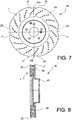
Figure 7 illustrates a front view on the wheel side of a disc having a braking band provided with radial recesses on its outer edge, in particular arc-shaped recesses, and a plurality of drillings on at least one of the braking surfaces thereof; -
Figure 8 illustrates a sectional view along line VIII - VIII of the disc inFigure 7 ; -
Figure 9 shows an axonometric view on the wheel side of a disc having a braking band provided with arc-shaped radial recesses on its outer edge in accordance with an embodiment; -
Figure 10 shows an axonometric view on the hub side of the disc inFigure 9 ; -
Figure 11 illustrates a front view on the wheel side of a disc having a braking band provided with radial recesses on its outer edge, in particular arc-shaped recesses, and a plurality of drillings on at least one of the braking surfaces thereof; -
Figure 12 illustrates a sectional view along line XI - XI of the disc inFigure 11 ; -
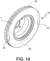
Figure 13 shows an axonometric view on the wheel side of a disc having a braking band provided with grooved radial recesses on its outer edge arranged on a chord of a circumference centred on the rotation axis of the disc in accordance with an embodiment; -
Figure 14 shows an axonometric view on the hub side of the disc inFigure 13 in which the grooves are angularly offset in the circumferential direction in relation to those of the opposed braking surface visible inFigure 13 ; -
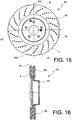
Figure 15 illustrates a front view on the wheel side of a ventilated disc having a braking band provided with radial recesses on its outer edge, in particular a levelling axially restrained only to the connection members of the two plates of the ventilated disc, and a plurality of drillings on at least one of the braking surfaces thereof; -
Figure 16 illustrates a sectional view along line XI - XI of the disc inFigure 14 ; -
Figure 17 shows an axonometric view on the wheel side of a disc having a braking band provided with radial recesses on its outer edge which are arc-shaped and angularly offset in the circumferential direction between the opposed braking surfaces, in accordance with the invention; -
Figure 18 shows an axonometric view on the hub side of the disc inFigure 17 , in which the arc-shaped radial recesses are angularly offset in the circumferential direction in relation to those of the opposed braking surface seen inFigure 13 ; -
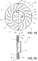
Figure 19 illustrates a front view on the wheel side of a disc having a braking band provided with radial recesses on its outer edge, in particular arc-shaped recesses, which is angularly offset in the circumferential direction between the opposed braking surfaces, and a plurality of drillings on at least one of the braking surfaces thereof; -
Figure 20 illustrates a sectional view along line XX - XX of the disc inFigure 19 ; -
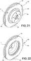
Figure 21 shows an axonometric view on the wheel side of a disc having a braking band provided with grooved radial recesses on its outer edge arranged on a chord of a circumference centred on the rotation axis of the disc, in accordance with an embodiment; -
Figure 22 shows an axonometric view on the hub side of the disc inFigure 21 ; -
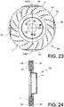
Figure 23 illustrates a front view on the wheel side of a disc having a braking band provided with radial recesses on its outer edge, in particular grooved recesses, arranged on a chord of a circumference centred on the rotation axis of the disc, and a plurality of drillings on at least one of the braking surfaces thereof; -
Figure 24 illustrates a sectional view along line XXIV - XXIV of the disc inFigure 23 ; -
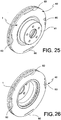
Figure 25 shows an axonometric view on the wheel side of a disc having a braking band provided with grooved radial recesses on its outer edge which are closed at the ends thereof, so as not to emerge onto the outer edge, and arranged on a chord of a circumference centred on the rotation axis of the disc, in accordance with an embodiment; -
Figure 26 shows an axonometric view on the hub side of the disc inFigure 25 ; -
Figure 27 illustrates a front view on the wheel side of a disc having a braking band provided with radial recesses on its outer edge, in particular grooved recesses, which are closed at the ends thereof, so as not to emerge onto the outer edge, arranged on a chord of a circumference centred on the disc rotation axis, and a plurality of drillings on at least one of the braking surfaces thereof; -
Figure 28 illustrates a sectional view along line XXVIII - XXVIII of the disc inFigure 27 ; -
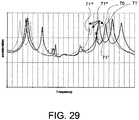
Figure 29 shows the frequency response of a disc without radial recesses, a mode of which is indicated by the reference numeral 70, compared to the frequency response of the same disc provided with radial recesses having preset first dimensions, with corresponding modes which are split in two and having a reduced width with reference numerals 70' and 70", and compared to the frequency response of the same disc provided with radial recesses having preset second minor dimensions, with corresponding modes which are split in two and having a reduced width with reference numerals 70''' and 70'''', - In accordance with a general embodiment, a
braking band 1 of a disc for brake disc comprises abody 2 having a pre-established rotation axis "a". Said body has a pre-established extension in the axial "a-a" and radial "r-r" directions in relation to said rotation axis (Figure 1 ). - Advantageously, said
body 2 is restrained in the axial direction by afirst braking surface 3 adapted to be rubbed by a first brake pad, supported by a caliper constrained to the vehicle and arranged astride of said band, in order to exert a braking action on the vehicle. - A
second braking surface 4, opposed to the first one in the axial direction, is adapted to be rubbed by a second brake pad, in order to exert a braking action on the vehicle. - Said opposed
braking surfaces braking volume 5 of said body. - Advantageously, said
first braking surface 3 comprises a first radiallyinner edge 6 which radially defines said surface on the rotation axis "a" side. Said first inner edge is inscribed by a firstinner edge line 7 which is closed and lying on a circumference with radius "R1i" of a pre-established dimension. - Preferably, said
first braking surface 3 comprises a first radiallyouter edge 8 which radially defines said surface on the opposed side to the rotation axis "a". Said first outer edge is circumscribed by a firstouter edge line 9, which is, for example, closed. - Advantageously, said
second braking surface 4 comprises a second radiallyinner edge 10 which radially defines said surface on the rotation axis "a" side. Said second inner edge is inscribed by a secondinner edge line 11 which is closed and lying on a circumference with radius "R2i" of a pre-established dimension. - With particular advantage, said second braking surface comprises a second radially
outer edge 12, which radially defines said surface on the opposed side to the rotation axis "a"; said second outer edge being circumscribed by a secondouter edge line 13, which is, for example, closed. - Preferably, said first and second outer edges are parts of a disc
outer edge 14 which radially defines said disc on the opposed side to said rotation axis "a". - In accordance with an embodiment, at least one
axial portion 15 of said discouter edge 14 is circumscribed by adisc edge line 16, which is, for example, closed, and comprises at least one angular portion A, B, C, D, which is radially recessed towards the rotation axis "a" to form an edgeouter recess 17 entering said braking volume 5 (for example,Figure 2 orFigure 17 ). - In accordance with a further embodiment, said at least one
axial portion 15 of said disc outer edge consists in at least two axial portions of discouter edge outer edge recess 17, 19 (Figures 17, 18 ,19, 20 ). - Advantageously, said two axial portions of disc
outer edge outer edge recess - In accordance with the invention, said at least one
outer edge recess axial portions - In accordance with a still further embodiment, said
disc edge line 16 comprises circumference lengths centred on the disc body axis, and concavity towards the axis, and at least onecircumference length 20 of opposed concavity, said edge line changing from convex to concave, and forming said at least oneouter edge recess 17 and/or 19. - In accordance with an embodiment, said
disc edge line 16 comprises circumference lengths that are centred on the disc body axis and concavity towards the axis, and at least onerectilinear length 21 lying on a straight line and forming said at least one outer edge recess. - Advantageously, said straight line which said
rectilinear length 21 lays on forms a chord on a circumference transversal to the rotation axis "a" and centred on said rotation axis. - In accordance with an embodiment, said disc
outer edge 14 circumscribed by saiddisc edge line 16 comprises at least two outer edge recesses 17 entering saidbraking volume 5. - Advantageously, said at least two
recesses 17 are equally spaced from each other. - In accordance with an embodiment, said at least one
outer recess outer edges - In accordance with an embodiment, said
band 1 is a ventilated braking band and comprises twoplates ventilation duct 22, said plates being connected by connection means 23 passing through saidventilation duct 22. - Advantageously, said at least one
outer recess 61 only involves said connection means 23 (Figures 15 and 16 ), for example, said radial recesses are formed by levelling of the connection means, advantageously according to a chord at a circumference centred on the band rotation axis. - In accordance with an embodiment, said connection means 23 are extended members or fins connecting the two plates in an essentially radial direction.
- In accordance with a further embodiment, said connection means are pillar members or pins which locally connect the two
plates - In accordance with an advantageous embodiment, said at least one outer recess 35, 36 only involves the radially
outer edge plate Figures 17 to 20 ). - In accordance with an embodiment, said at least one
axial portion outer edge 14 only partially involves the axial thickness of said disc body and, by being recessed in saidbraking volume 5 delimited by said braking surfaces 3, 4, it forms at least onegroove 24 which at least partially splits at least one of saidbraking surfaces 3 and/or 4 (Figures 13 ,14 ,21, 22 ,23, 24 ,25, 26 ,27, 28 ). - Advantageously, said
groove 24 comprises at least one rectilinear portion. - With further advantage, said
groove 60 is closed at the ends thereof, and is not joined to the radiallyouter edge 8 and/or 12 of the braking surface (Figures 25 to 28 ). - In accordance with an embodiment, said radial outer recess is achieved with at least one groove drilled on at least one braking surface that is arranged on a chord of a circumference centred on the band surface axis. This at least one groove only very slightly reduces the braking surface extension, affecting the vibration modes of the braking band and eliminating the squeal generated during the braking action, but it does not considerably modify the surface which the braking pads act on.
- In accordance with an embodiment, the braking band has at least one window or hole on at least one of the braking surfaces, for example blind or through windows or holes and, for example, a plurality of windows or holes.
- In accordance with an embodiment, a braking band provided with opposed braking surfaces comprises radial recesses on the outer edges of said braking surfaces, and the radial recesses of a first braking surface are angularly offset in the circumferential direction in relation to the radial recesses of the opposed braking surface.
- In accordance with an embodiment, a braking band provided with opposed braking surfaces comprises grooves lying on chords of circumferences centred on a band rotation axis and debouching on the outer edges of said braking surfaces, and the grooves of a first braking surface are angularly offset in the circumferential direction in relation to the grooves of the opposed braking surface.
- In accordance with an embodiment, a
brake disc 40 of brake disc comprises abraking band 1 according to any one of the previously-described embodiments. - In accordance with an embodiment, said
disc 40 comprises a connectingbell 41 of said disc at a wheel hub of a vehicle suspension. Advantageously, saidbell 41 is integral to saiddisc 40. - Some exemplary manufacturing methods for a
braking band 1 and adisc 40 as previously described will be described below. - In accordance with an embodiment, a method for manufacturing a
braking band 1 comprises the following steps: - providing a
body 2 having a pre-established rotation axis "a", said body having an extension in the axial and radial directions "r-r" to said rotation axis; - restraining said body in the axial direction by means of a
first braking surface 3 adapted to be rubbed by a brake pad, in order to exert a braking action on a vehicle; and - restraining said body in the axial direction by means of a
second braking surface 4, opposed to the first one in the axial direction, and adapted to be rubbed by a brake pad, in order to exert a braking action on a vehicle; - axially restraining a
braking volume 5 of said body by means of saidopposed braking surfaces - creating a first radially
inner edge 6 in said first braking surface which radially defines said surface on the rotation axis side, said first inner edge being inscribed by a firstinner edge line 7 which is closed and lying on a circumference with radius "R1i" of a pre-established dimension; - creating a first radially
outer edge 8 in said first braking surface which radially defines said surface on the opposed side to the rotation axis, said first outer edge being circumscribed by a firstouter edge line 9; - creating a second radially
inner edge 10 in said second braking surface which radially defines said surface on the rotation axis side, said second inner edge being inscribed by a secondinner edge line 11 which is closed and lying on a circumference with radius "R2i" of a pre-established dimension; - creating a second radially
outer edge 12 in said second braking surface which radially defines said surface on the opposed side to the rotation axis, said second outer edge being circumscribed by a secondouter edge line 13; - creating a disc
outer edge 14 which radially defines said disc on the opposed side to said rotation axis comprising said first and secondouter edges - creating in at least one
axial portion 15 of said discouter edge 14, circumscribed by adisc edge line 16, at least one angular portion A, B, C, D which is radially recessed towards the rotation axis "a" to form an edgeouter recess 17 entering saidbraking volume 5. - In accordance with a particular embodiment of the method, said radial recess is achieved by milling.
- With further advantage, said radial recess is achieved by levelling.
- In accordance with a particular embodiment of the method, at least two axial portions of disc
outer edge outer edge recess - Advantageously, said two axial portions of disc
outer edge outer edge recess - According to the invention, said at least one
outer edge recess - It should be understood that the solution may take, in its practical implementation, also forms and configurations other than the one set forth above, without however departing from the present scope of protection s defined by the appended claims. Furthermore, all the details may be replaced by technically equivalent elements, and the forms, dimensions, and materials employed may be any, according to the requirements.
Claims (12)
- A braking band (1) of a disc for brake disc comprising:- a body (2) having a pre-established rotation axis (a), said body having an extension in the axial and radial directions in relation to said rotation axis;- said body being restrained in the axial direction by a first braking surface (3) adapted to be rubbed by a brake pad, in order to exert a braking action on a vehicle; and- a second braking surface (4), opposed to the first one in the axial direction, and adapted to be rubbed by a brake pad, in order to exert a braking action on a vehicle;- said opposed braking surfaces (3, 4) axially define a braking volume (5) of said body;- said first braking surface comprising a first radially inner edge (6) which radially defines said surface on the rotation axis side, said first inner edge being inscribed by a first inner edge line (7) which is closed and lying on a circumference with radius (R1i) of a pre-established dimension;- said first braking surface comprising a first radially outer edge (8) which radially defines said surface on the opposed side to the rotation axis, said first outer edge being circumscribed by a closed first outer edge line (9);- said second braking surface comprising a second radially inner edge (10) which radially defines said surface on the rotation axis side, said second inner edge being inscribed by a second inner edge line (11) which is closed and lying on a circumference with radius (R2i) of a pre-established dimension;- said second braking surface comprising a second radially outer edge (12) which radially defines said surface on the opposed side to the rotation axis, said second outer edge being circumscribed by a closed second outer edge line (13) ;- said first and second outer edges being parts of a disc outer edge (14) which radially defines said disc on the opposed side to said rotation axis;- at least one axial portion (15) of said disc outer edge being circumscribed by a closed disc edge line (16) comprising at least one angular portion (A, B, C, D) which is radially recessed towards the rotation axis to form an edge outer recess (17) entering said braking volume;- said at least one axial portion consists in at least two axial portions of disc outer edge (15, 18), each forming at least one outer edge recess (17, 19);wherein- said two axial portions of disc outer edge (15, 18) are axially spaced apart from each other;
characterized by the fact that
the outer edge recesses (17, 19) provided in the radially outer edges of the braking surfaces (3, 4) are present in the opposed braking surfaces (3, 4) and are angularly offset one to the other in a circumferential direction to the braking band, so as not to completely overlap each other in the axial direction. - The braking band according to claim 1, wherein said at least one outer edge recess (17, 19) of said at least two outer edge axial portions are four in number and 90DEG angularly spaced apart from each other (E).
- The braking band according to claim 1, wherein said disc edge line (16) comprises circumference lengths that are centred on the disc body axis and concavity towards the axis, and at least one rectilinear length (21) lying on a straight line and forming said at least one outer edge recess and
wherein said straight line, which said rectilinear length (21) lies on, forms a chord at a circumference transversal to the rotation axis (a) centred on said rotation axis. - The braking band according to any preceding claim, wherein said disc outer edge circumscribed by said closed disc edge line (16) comprises at least two edge outer recesses entering said braking volume.
- The braking band according to claim 4, wherein said at least two recesses are equally spaced from each other.
- The braking band according to any preceding claim, wherein said at least one outer recess is provided on said first or second lines of first or second outer edges of said first or second braking surfaces.
- The braking band according to any preceding claim, wherein said surface comprises two plates, the gap between the plates defining a ventilation duct (22), said plates being connected by connection means (23) passing through said ventilation duct and wherein said at least one outer recess only involves the radially outer edge of at least one plate.
- A braking disc of a brake disc comprising a braking band according to any preceding claim and comprising a connecting bell of said disc to a wheel hub of a vehicle suspension, wherein said bell is integral to said disc.
- A method for manufacturing a braking band, comprising the following steps:- providing a body (2) having a pre-established rotation axis (a), said body having an extension in the axial and radial directions to said rotation axis;- restraining said body in the axial direction by means of a first braking surface (3) adapted to be rubbed by a brake pad, in order to exert a braking action on a vehicle and- restraining said body in the axial direction by means of a second braking surface (4), opposed to the first one in the axial direction, and adapted to be rubbed by a brake pad, in order to exert a braking action on a vehicle;- axially restraining a braking volume (5) of said body by means of said opposed braking surfaces (3, 4);- creating a first radially inner edge (6) in said first braking surface which radially defines said surface on the rotation axis side, said first inner edge being inscribed by a first inner edge line (7) which is closed and lying on a circumference with radius (R1i) of a pre-established dimension;- creating a first radially outer edge (8) in said first braking surface which radially defines said surface on the opposed side to the rotation axis, said first outer edge being circumscribed by a closed first outer edge line (9);- creating a second radially inner edge (10) in said second braking surface which radially defines said surface on the rotation axis side, said second inner edge being inscribed by a second inner edge line (11) which is closed and lying on a circumference with radius (R2i) of a pre-established dimension;- creating a second radially outer edge (12) in said second braking surface which radially defines said surface on the opposed side to the rotation axis, said second outer edge being circumscribed by a closed second outer edge line (13) ;- creating a disc outer edge (14) which radially defines said disc on the opposed side to said rotation axis comprising said first and second outer edges;- creating, in at least one axial portion (15) of said disc outer edge, circumscribed by a closed disc edge line (16), at least one angular portion (A, B, C, D) which is radially recessed towards the rotation axis to form an edge outer recess (17) entering said braking volume;- at least two axial portions of disc outer edge (15, 18) are created, each forming at least one outer edge recess (17, 19);- said two axial portions of disc outer edge (15, 18) are created axially spaced apart from each other;characterized in that it comprises the further step of:
the outer edge recesses (17, 19) provided in the radially outer edges of the braking surfaces (3, 4) are created in the opposed braking surfaces (3, 4) and are created angularly offset one to the other in a circumferential direction to the braking band, so as not to completely overlap each other in the axial direction. - The method according to claim 9, wherein said radial recess is achieved by milling.
- The method according to the claim 9 or 10, wherein said braking band is ventilated in at least one of the braking surfaces thereof, drilling at least one blind or through hole in said at least one braking surface.
- The method according to claim 9, wherein said radial recess is achieved by levelling.
Priority Applications (1)
| Application Number | Priority Date | Filing Date | Title |
|---|---|---|---|
| HUE07866801A HUE057019T2 (en) | 2007-12-13 | 2007-12-13 | Braking band of a disc for a brake disc, disc of a brake disc, and method of manufacturing the same |
Applications Claiming Priority (1)
| Application Number | Priority Date | Filing Date | Title |
|---|---|---|---|
| PCT/IT2007/000869 WO2009075002A1 (en) | 2007-12-13 | 2007-12-13 | Braking band of a disc for a brake disc, disc of a brake disc, and method -of manufacturing the same |
Publications (2)
| Publication Number | Publication Date |
|---|---|
| EP2232093A1 EP2232093A1 (en) | 2010-09-29 |
| EP2232093B1 true EP2232093B1 (en) | 2021-09-01 |
Family
ID=39718303
Family Applications (1)
| Application Number | Title | Priority Date | Filing Date |
|---|---|---|---|
| EP07866801.9A Active EP2232093B1 (en) | 2007-12-13 | 2007-12-13 | Braking band of a disc for a brake disc, disc of a brake disc, and method of manufacturing the same |
Country Status (3)
| Country | Link |
|---|---|
| EP (1) | EP2232093B1 (en) |
| HU (1) | HUE057019T2 (en) |
| WO (1) | WO2009075002A1 (en) |
Families Citing this family (4)
| Publication number | Priority date | Publication date | Assignee | Title |
|---|---|---|---|---|
| US8146719B2 (en) * | 2008-04-25 | 2012-04-03 | GM Global Technology Operations LLC | Disk brake friction surfaces with tunable indent patterns for minimizing brake pad radial taper wear |
| US8287055B2 (en) | 2010-09-28 | 2012-10-16 | Robert Bosch Gmbh | Brake control of a vehicle based on driver behavior |
| FR2969727B1 (en) * | 2010-12-24 | 2013-11-22 | Sncf | DISC BRAKING DEVICE FOR RAILWAY VEHICLE |
| DE102011115290A1 (en) * | 2011-09-29 | 2013-04-04 | Audi Ag | One-piece brake disk, has friction ring and pot-shaped carrier part rotationally symmetrically formed, where disk simultaneously has two types of eccentricities that have trochoid or waves of any order or polygons with rounded corners |
Family Cites Families (5)
| Publication number | Priority date | Publication date | Assignee | Title |
|---|---|---|---|---|
| DE4002695A1 (en) * | 1990-01-27 | 1991-08-01 | Porsche Ag | BRAKE DISC |
| JPH09126257A (en) * | 1995-10-27 | 1997-05-13 | Shinko Electric Co Ltd | Friction plate of friction joint |
| US6131707A (en) * | 1997-06-04 | 2000-10-17 | Kelsey-Hayes Company | Disc brake rotor and method for producing same |
| AU8681398A (en) * | 1998-03-31 | 1999-10-18 | Hayes Lemmerz International, Inc. | Brake rotor with non-circular ring section |
| ITMI20050099A1 (en) * | 2005-01-25 | 2006-07-26 | Sunstar Logistic Singapore Pte | BRAKE DISC WITH IRREGULAR PROFILE AND BRAKE INCLUDING THE DISC |
-
2007
- 2007-12-13 EP EP07866801.9A patent/EP2232093B1/en active Active
- 2007-12-13 WO PCT/IT2007/000869 patent/WO2009075002A1/en not_active Ceased
- 2007-12-13 HU HUE07866801A patent/HUE057019T2/en unknown
Also Published As
| Publication number | Publication date |
|---|---|
| EP2232093A1 (en) | 2010-09-29 |
| WO2009075002A1 (en) | 2009-06-18 |
| HUE057019T2 (en) | 2022-04-28 |
Similar Documents
| Publication | Publication Date | Title |
|---|---|---|
| EP2025965B1 (en) | Brake Disc Assembly | |
| US8474580B2 (en) | Floating brake disc | |
| EP3163112B1 (en) | Brake disc | |
| US10557510B2 (en) | Brake disc for a bicycle | |
| US9062730B2 (en) | Internally ventilated brake disk for disk brakes | |
| US7958978B2 (en) | Multi-disc brake hub assembly with disc slide pins | |
| JP2011514862A (en) | Outer hub barrel mounting rotor | |
| US5474161A (en) | Rotor for a disc brake assembly and method of making same | |
| US7331433B2 (en) | Brake disc for automotive disc brake assembly | |
| US10280995B2 (en) | Reinforced caliper housing | |
| WO2009075002A1 (en) | Braking band of a disc for a brake disc, disc of a brake disc, and method -of manufacturing the same | |
| EP3750720B1 (en) | Vehicle wheel for passenger cars | |
| JP6806744B2 (en) | Vehicle wheels and vehicles | |
| EP3491264B1 (en) | Brake disc | |
| EP1382878B1 (en) | Brake rotor | |
| US10781877B2 (en) | Hub for mounting a brake disc to a vehicle axis | |
| EP1596088B1 (en) | Brake disk for vehicle | |
| US20090145702A1 (en) | Brake pad for a vehicle disc brake assembly | |
| EP3702636B1 (en) | Rotor assembly for a disc brake system | |
| EP1760351B1 (en) | Disk braking device and motorcycle provided with the disk braking device | |
| US20220080771A1 (en) | Non-pneumatic wheel with press fit hub | |
| JP7389050B2 (en) | Manufactured vehicle wheel with wheel disc having lightweight pockets | |
| EP4574445A1 (en) | Polygonal wheel for vehicles | |
| JP2010048302A (en) | Disk brake | |
| WO2005075847A1 (en) | Disc brake rotor and method for producing same |
Legal Events
| Date | Code | Title | Description |
|---|---|---|---|
| PUAI | Public reference made under article 153(3) epc to a published international application that has entered the european phase |
Free format text: ORIGINAL CODE: 0009012 |
|
| 17P | Request for examination filed |
Effective date: 20100712 |
|
| AK | Designated contracting states |
Kind code of ref document: A1 Designated state(s): AT BE BG CH CY CZ DE DK EE ES FI FR GB GR HU IE IS IT LI LT LU LV MC MT NL PL PT RO SE SI SK TR |
|
| AX | Request for extension of the european patent |
Extension state: AL BA HR MK RS |
|
| DAX | Request for extension of the european patent (deleted) | ||
| STAA | Information on the status of an ep patent application or granted ep patent |
Free format text: STATUS: EXAMINATION IS IN PROGRESS |
|
| 17Q | First examination report despatched |
Effective date: 20170802 |
|
| GRAP | Despatch of communication of intention to grant a patent |
Free format text: ORIGINAL CODE: EPIDOSNIGR1 |
|
| STAA | Information on the status of an ep patent application or granted ep patent |
Free format text: STATUS: GRANT OF PATENT IS INTENDED |
|
| INTG | Intention to grant announced |
Effective date: 20210412 |
|
| RAP3 | Party data changed (applicant data changed or rights of an application transferred) |
Owner name: BREMBO S.P.A. |
|
| GRAS | Grant fee paid |
Free format text: ORIGINAL CODE: EPIDOSNIGR3 |
|
| GRAA | (expected) grant |
Free format text: ORIGINAL CODE: 0009210 |
|
| STAA | Information on the status of an ep patent application or granted ep patent |
Free format text: STATUS: THE PATENT HAS BEEN GRANTED |
|
| RAP3 | Party data changed (applicant data changed or rights of an application transferred) |
Owner name: BREMBO S.P.A. |
|
| AK | Designated contracting states |
Kind code of ref document: B1 Designated state(s): AT BE BG CH CY CZ DE DK EE ES FI FR GB GR HU IE IS IT LI LT LU LV MC MT NL PL PT RO SE SI SK TR |
|
| REG | Reference to a national code |
Ref country code: GB Ref legal event code: FG4D |
|
| REG | Reference to a national code |
Ref country code: CH Ref legal event code: EP Ref country code: AT Ref legal event code: REF Ref document number: 1426552 Country of ref document: AT Kind code of ref document: T Effective date: 20210915 |
|
| REG | Reference to a national code |
Ref country code: DE Ref legal event code: R096 Ref document number: 602007061288 Country of ref document: DE |
|
| REG | Reference to a national code |
Ref country code: IE Ref legal event code: FG4D |
|
| REG | Reference to a national code |
Ref country code: LT Ref legal event code: MG9D |
|
| REG | Reference to a national code |
Ref country code: NL Ref legal event code: MP Effective date: 20210901 |
|
| PG25 | Lapsed in a contracting state [announced via postgrant information from national office to epo] |
Ref country code: SE Free format text: LAPSE BECAUSE OF FAILURE TO SUBMIT A TRANSLATION OF THE DESCRIPTION OR TO PAY THE FEE WITHIN THE PRESCRIBED TIME-LIMIT Effective date: 20210901 Ref country code: FI Free format text: LAPSE BECAUSE OF FAILURE TO SUBMIT A TRANSLATION OF THE DESCRIPTION OR TO PAY THE FEE WITHIN THE PRESCRIBED TIME-LIMIT Effective date: 20210901 Ref country code: ES Free format text: LAPSE BECAUSE OF FAILURE TO SUBMIT A TRANSLATION OF THE DESCRIPTION OR TO PAY THE FEE WITHIN THE PRESCRIBED TIME-LIMIT Effective date: 20210901 Ref country code: BG Free format text: LAPSE BECAUSE OF FAILURE TO SUBMIT A TRANSLATION OF THE DESCRIPTION OR TO PAY THE FEE WITHIN THE PRESCRIBED TIME-LIMIT Effective date: 20211201 Ref country code: LT Free format text: LAPSE BECAUSE OF FAILURE TO SUBMIT A TRANSLATION OF THE DESCRIPTION OR TO PAY THE FEE WITHIN THE PRESCRIBED TIME-LIMIT Effective date: 20210901 |
|
| REG | Reference to a national code |
Ref country code: AT Ref legal event code: MK05 Ref document number: 1426552 Country of ref document: AT Kind code of ref document: T Effective date: 20210901 |
|
| REG | Reference to a national code |
Ref country code: SK Ref legal event code: T3 Ref document number: E 38898 Country of ref document: SK |
|
| PG25 | Lapsed in a contracting state [announced via postgrant information from national office to epo] |
Ref country code: PL Free format text: LAPSE BECAUSE OF FAILURE TO SUBMIT A TRANSLATION OF THE DESCRIPTION OR TO PAY THE FEE WITHIN THE PRESCRIBED TIME-LIMIT Effective date: 20210901 Ref country code: LV Free format text: LAPSE BECAUSE OF FAILURE TO SUBMIT A TRANSLATION OF THE DESCRIPTION OR TO PAY THE FEE WITHIN THE PRESCRIBED TIME-LIMIT Effective date: 20210901 Ref country code: GR Free format text: LAPSE BECAUSE OF FAILURE TO SUBMIT A TRANSLATION OF THE DESCRIPTION OR TO PAY THE FEE WITHIN THE PRESCRIBED TIME-LIMIT Effective date: 20211202 |
|
| REG | Reference to a national code |
Ref country code: HU Ref legal event code: AG4A Ref document number: E057019 Country of ref document: HU |
|
| PG25 | Lapsed in a contracting state [announced via postgrant information from national office to epo] |
Ref country code: AT Free format text: LAPSE BECAUSE OF FAILURE TO SUBMIT A TRANSLATION OF THE DESCRIPTION OR TO PAY THE FEE WITHIN THE PRESCRIBED TIME-LIMIT Effective date: 20210901 |
|
| PG25 | Lapsed in a contracting state [announced via postgrant information from national office to epo] |
Ref country code: IS Free format text: LAPSE BECAUSE OF FAILURE TO SUBMIT A TRANSLATION OF THE DESCRIPTION OR TO PAY THE FEE WITHIN THE PRESCRIBED TIME-LIMIT Effective date: 20220101 Ref country code: RO Free format text: LAPSE BECAUSE OF FAILURE TO SUBMIT A TRANSLATION OF THE DESCRIPTION OR TO PAY THE FEE WITHIN THE PRESCRIBED TIME-LIMIT Effective date: 20210901 Ref country code: PT Free format text: LAPSE BECAUSE OF FAILURE TO SUBMIT A TRANSLATION OF THE DESCRIPTION OR TO PAY THE FEE WITHIN THE PRESCRIBED TIME-LIMIT Effective date: 20220103 Ref country code: NL Free format text: LAPSE BECAUSE OF FAILURE TO SUBMIT A TRANSLATION OF THE DESCRIPTION OR TO PAY THE FEE WITHIN THE PRESCRIBED TIME-LIMIT Effective date: 20210901 Ref country code: EE Free format text: LAPSE BECAUSE OF FAILURE TO SUBMIT A TRANSLATION OF THE DESCRIPTION OR TO PAY THE FEE WITHIN THE PRESCRIBED TIME-LIMIT Effective date: 20210901 Ref country code: CZ Free format text: LAPSE BECAUSE OF FAILURE TO SUBMIT A TRANSLATION OF THE DESCRIPTION OR TO PAY THE FEE WITHIN THE PRESCRIBED TIME-LIMIT Effective date: 20210901 |
|
| REG | Reference to a national code |
Ref country code: DE Ref legal event code: R097 Ref document number: 602007061288 Country of ref document: DE |
|
| PLBE | No opposition filed within time limit |
Free format text: ORIGINAL CODE: 0009261 |
|
| STAA | Information on the status of an ep patent application or granted ep patent |
Free format text: STATUS: NO OPPOSITION FILED WITHIN TIME LIMIT |
|
| PG25 | Lapsed in a contracting state [announced via postgrant information from national office to epo] |
Ref country code: MC Free format text: LAPSE BECAUSE OF FAILURE TO SUBMIT A TRANSLATION OF THE DESCRIPTION OR TO PAY THE FEE WITHIN THE PRESCRIBED TIME-LIMIT Effective date: 20210901 Ref country code: IT Free format text: LAPSE BECAUSE OF FAILURE TO SUBMIT A TRANSLATION OF THE DESCRIPTION OR TO PAY THE FEE WITHIN THE PRESCRIBED TIME-LIMIT Effective date: 20210901 Ref country code: DK Free format text: LAPSE BECAUSE OF FAILURE TO SUBMIT A TRANSLATION OF THE DESCRIPTION OR TO PAY THE FEE WITHIN THE PRESCRIBED TIME-LIMIT Effective date: 20210901 |
|
| REG | Reference to a national code |
Ref country code: CH Ref legal event code: PL |
|
| 26N | No opposition filed |
Effective date: 20220602 |
|
| PG25 | Lapsed in a contracting state [announced via postgrant information from national office to epo] |
Ref country code: SI Free format text: LAPSE BECAUSE OF FAILURE TO SUBMIT A TRANSLATION OF THE DESCRIPTION OR TO PAY THE FEE WITHIN THE PRESCRIBED TIME-LIMIT Effective date: 20210901 |
|
| REG | Reference to a national code |
Ref country code: BE Ref legal event code: MM Effective date: 20211231 |
|
| PG25 | Lapsed in a contracting state [announced via postgrant information from national office to epo] |
Ref country code: LU Free format text: LAPSE BECAUSE OF NON-PAYMENT OF DUE FEES Effective date: 20211213 Ref country code: IE Free format text: LAPSE BECAUSE OF NON-PAYMENT OF DUE FEES Effective date: 20211213 |
|
| PG25 | Lapsed in a contracting state [announced via postgrant information from national office to epo] |
Ref country code: BE Free format text: LAPSE BECAUSE OF NON-PAYMENT OF DUE FEES Effective date: 20211231 |
|
| PG25 | Lapsed in a contracting state [announced via postgrant information from national office to epo] |
Ref country code: LI Free format text: LAPSE BECAUSE OF NON-PAYMENT OF DUE FEES Effective date: 20211231 Ref country code: CH Free format text: LAPSE BECAUSE OF NON-PAYMENT OF DUE FEES Effective date: 20211231 |
|
| PG25 | Lapsed in a contracting state [announced via postgrant information from national office to epo] |
Ref country code: CY Free format text: LAPSE BECAUSE OF FAILURE TO SUBMIT A TRANSLATION OF THE DESCRIPTION OR TO PAY THE FEE WITHIN THE PRESCRIBED TIME-LIMIT Effective date: 20210901 |
|
| P01 | Opt-out of the competence of the unified patent court (upc) registered |
Effective date: 20230526 |
|
| PG25 | Lapsed in a contracting state [announced via postgrant information from national office to epo] |
Ref country code: TR Free format text: LAPSE BECAUSE OF FAILURE TO SUBMIT A TRANSLATION OF THE DESCRIPTION OR TO PAY THE FEE WITHIN THE PRESCRIBED TIME-LIMIT Effective date: 20210901 |
|
| PG25 | Lapsed in a contracting state [announced via postgrant information from national office to epo] |
Ref country code: MT Free format text: LAPSE BECAUSE OF FAILURE TO SUBMIT A TRANSLATION OF THE DESCRIPTION OR TO PAY THE FEE WITHIN THE PRESCRIBED TIME-LIMIT Effective date: 20210901 |
|
| PGFP | Annual fee paid to national office [announced via postgrant information from national office to epo] |
Ref country code: GB Payment date: 20251219 Year of fee payment: 19 |
|
| PGFP | Annual fee paid to national office [announced via postgrant information from national office to epo] |
Ref country code: HU Payment date: 20251223 Year of fee payment: 19 Ref country code: FR Payment date: 20251128 Year of fee payment: 19 |
|
| PGFP | Annual fee paid to national office [announced via postgrant information from national office to epo] |
Ref country code: SK Payment date: 20251210 Year of fee payment: 19 |
|
| PGFP | Annual fee paid to national office [announced via postgrant information from national office to epo] |
Ref country code: DE Payment date: 20251222 Year of fee payment: 19 |