EP2231027B1 - System und vorrichtung zum verschliessen einer öffnung - Google Patents
System und vorrichtung zum verschliessen einer öffnung Download PDFInfo
- Publication number
- EP2231027B1 EP2231027B1 EP08861930.9A EP08861930A EP2231027B1 EP 2231027 B1 EP2231027 B1 EP 2231027B1 EP 08861930 A EP08861930 A EP 08861930A EP 2231027 B1 EP2231027 B1 EP 2231027B1
- Authority
- EP
- European Patent Office
- Prior art keywords
- suture
- fastening device
- apex
- looped
- distance
- Prior art date
- Legal status (The legal status is an assumption and is not a legal conclusion. Google has not performed a legal analysis and makes no representation as to the accuracy of the status listed.)
- Not-in-force
Links
- 230000006835 compression Effects 0.000 claims description 10
- 238000007906 compression Methods 0.000 claims description 10
- 239000012858 resilient material Substances 0.000 claims description 3
- 239000012781 shape memory material Substances 0.000 claims description 3
- 239000000463 material Substances 0.000 description 12
- 230000002792 vascular Effects 0.000 description 12
- 238000000034 method Methods 0.000 description 11
- 230000023597 hemostasis Effects 0.000 description 7
- 238000013459 approach Methods 0.000 description 5
- 210000004204 blood vessel Anatomy 0.000 description 5
- 238000004891 communication Methods 0.000 description 5
- 208000032843 Hemorrhage Diseases 0.000 description 4
- 230000015572 biosynthetic process Effects 0.000 description 4
- 230000000740 bleeding effect Effects 0.000 description 4
- 230000008859 change Effects 0.000 description 4
- 102000008186 Collagen Human genes 0.000 description 3
- 108010035532 Collagen Proteins 0.000 description 3
- 208000007536 Thrombosis Diseases 0.000 description 3
- 229920001436 collagen Polymers 0.000 description 3
- 230000007423 decrease Effects 0.000 description 3
- 238000007789 sealing Methods 0.000 description 3
- 230000007704 transition Effects 0.000 description 3
- 208000009087 False Aneurysm Diseases 0.000 description 2
- 206010018852 Haematoma Diseases 0.000 description 2
- 206010048975 Vascular pseudoaneurysm Diseases 0.000 description 2
- 239000008280 blood Substances 0.000 description 2
- 210000004369 blood Anatomy 0.000 description 2
- 238000005516 engineering process Methods 0.000 description 2
- KKJUPNGICOCCDW-UHFFFAOYSA-N 7-N,N-Dimethylamino-1,2,3,4,5-pentathiocyclooctane Chemical compound CN(C)C1CSSSSSC1 KKJUPNGICOCCDW-UHFFFAOYSA-N 0.000 description 1
- 206010067484 Adverse reaction Diseases 0.000 description 1
- 206010003226 Arteriovenous fistula Diseases 0.000 description 1
- 208000031481 Pathologic Constriction Diseases 0.000 description 1
- 206010053648 Vascular occlusion Diseases 0.000 description 1
- 230000006838 adverse reaction Effects 0.000 description 1
- 229940035676 analgesics Drugs 0.000 description 1
- 238000002399 angioplasty Methods 0.000 description 1
- 239000000730 antalgic agent Substances 0.000 description 1
- 239000003146 anticoagulant agent Substances 0.000 description 1
- 229940127219 anticoagulant drug Drugs 0.000 description 1
- 230000017531 blood circulation Effects 0.000 description 1
- 230000000747 cardiac effect Effects 0.000 description 1
- 230000035602 clotting Effects 0.000 description 1
- 230000003111 delayed effect Effects 0.000 description 1
- 230000006870 function Effects 0.000 description 1
- 239000007943 implant Substances 0.000 description 1
- 208000015181 infectious disease Diseases 0.000 description 1
- 208000028867 ischemia Diseases 0.000 description 1
- 208000010125 myocardial infarction Diseases 0.000 description 1
- 230000003287 optical effect Effects 0.000 description 1
- 230000008569 process Effects 0.000 description 1
- 230000002040 relaxant effect Effects 0.000 description 1
- 208000037804 stenosis Diseases 0.000 description 1
- 230000036262 stenosis Effects 0.000 description 1
- 238000011477 surgical intervention Methods 0.000 description 1
- 238000002560 therapeutic procedure Methods 0.000 description 1
- 230000002885 thrombogenetic effect Effects 0.000 description 1
- 238000011144 upstream manufacturing Methods 0.000 description 1
- 208000021331 vascular occlusion disease Diseases 0.000 description 1
Images



Classifications
-
- A—HUMAN NECESSITIES
- A61—MEDICAL OR VETERINARY SCIENCE; HYGIENE
- A61B—DIAGNOSIS; SURGERY; IDENTIFICATION
- A61B17/00—Surgical instruments, devices or methods
- A61B17/04—Surgical instruments, devices or methods for suturing wounds; Holders or packages for needles or suture materials
- A61B17/0487—Suture clamps, clips or locks, e.g. for replacing suture knots; Instruments for applying or removing suture clamps, clips or locks
-
- A—HUMAN NECESSITIES
- A61—MEDICAL OR VETERINARY SCIENCE; HYGIENE
- A61B—DIAGNOSIS; SURGERY; IDENTIFICATION
- A61B17/00—Surgical instruments, devices or methods
- A61B2017/00831—Material properties
- A61B2017/00867—Material properties shape memory effect
-
- A—HUMAN NECESSITIES
- A61—MEDICAL OR VETERINARY SCIENCE; HYGIENE
- A61B—DIAGNOSIS; SURGERY; IDENTIFICATION
- A61B17/00—Surgical instruments, devices or methods
- A61B17/04—Surgical instruments, devices or methods for suturing wounds; Holders or packages for needles or suture materials
- A61B17/0487—Suture clamps, clips or locks, e.g. for replacing suture knots; Instruments for applying or removing suture clamps, clips or locks
- A61B2017/0488—Instruments for applying suture clamps, clips or locks
Definitions
- the present invention relates generally to systems, and devices for closing an opening. More particularly, the present invention relates systems and devices for percutaneous closure of arterial and venous puncture sites, which are usually accessed through a tissue tract.
- a catheter is introduced to the vascular system at a convenient access location and guided through the vascular system to a target location using established techniques.
- Such procedures require vascular access, which is usually established during the well-known Seldinger technique, as described, for example, in William Grossman's Cardiac Catheterization and Angioplasty, 3rd Ed., Lea and Febiger, Philadelphia, 1986 .
- vascular access is generally provided through an introducer sheath, which is positioned to extend from outside the patient body into the vascular lumen.
- the compression procedure is further uncomfortable for the patient and frequently requires analgesics to be tolerable.
- the application of excessive pressure can at times totally occlude the underlying blood vessel, resulting in ischemia and/or thrombosis.
- the patient typically remains recumbent from four to as much as 12 hours or more under close observation so as to assure continued hemostasis.
- renewed bleeding may occur, resulting in blood loss through the tract, hematoma, and/or pseudo-aneurysm formation, as well as arteriovenous fistula formation.
- bioabsorbable fasteners or sealing bodies to stop bleeding has previously been proposed.
- these approaches rely on the placement of a thrombogenic and bioabsorbable material, such as collagen, at the superficial arterial wall over the puncture site. While potentially effective, this approach suffers from a number of problems. It can be difficult to properly locate the interface of the overlying tissue and the adventitial surface of the blood vessel. Locating the fastener too far from that interface can result in failure to provide hemostasis, and subsequent hematoma and/or pseudo-aneurysm formation.
- intravascular clots and/or collagen pieces with thrombus attached can form and embolize downstream, causing vascular occlusion.
- thrombus formation on the surface of a sealing body protruding into the lumen can cause a stenosis, which can obstruct normal blood flow.
- Other possible complications include infection, as well as adverse reaction to the collagen or other implant.
- a suture-applying device is introduced through the tissue tract with a distal end of the device extending through the vascular puncture.
- One or more needles in the device are then used to draw the suture through the blood vessel wall on opposite sides of the puncture, and the suture is secured directly over the adventitial surface of the blood vessel wall to provide highly reliable closure.
- a suture is fastened with knots.
- knots are often tied proximally and then advanced into proximity with the blood vessel where the knots are tightened to secure a suture. Securing a suture maintains the apposition provided above to maintain hemostasis.
- tying knots can be a time consuming process.
- U.S. Patent Application Publication No. 2007/049970 A1 discloses a suture fastening device having the features of the the preamble of claim 1.
- a suture-fastening device is provided herein that includes a looped body as claimed in claim 1.
- a system for maintaining apposition in a suture.
- the system includes a deployment device, the deployment device having a housing and an actuator assembly according to claim 6.
- the system also includes a suture-fastening device according to claim 1.
- the deployment device is configured to move the suture-fastening device from the pre-deployed position to the deployed position.
- a suture-fastening device can be used to retain and/or provide apposition for a suture that has been deployed to close an opening in tissue.
- the suture-fastening device includes at least a distal loop portion that moves from an expanded state having a first diameter to a constricted state having a second diameter, the second diameter being less than the first.
- the closure device also includes a proximal loop portion.
- a suture-fastening device is provided in which the diameter of a distal loop decreases while the diameter of a proximal loop increases as the suture-fastening device is deployed.
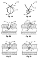
- FIGS. 1A and 1B illustrate a schematic representation of an exemplary suture-fastening device 100 that includes a looped portion 110, such as a distal loop.
- the suture-fastening device 100 may also include a second portion 120, such as a proximal portion. Details of the second portion 120 have been removed for simplicity of the discussion of the general operation of the suture-fastening device 100.
- the suture-fastening device 100 illustrated includes a generally circularly-shaped looped portion 110. Although the generally circular shape is illustrated for ease of reference only, it will be appreciated that other shapes and configurations may also be utilized.
- the suture-fastening device 100 moves between an expanded state illustrated in Fig. 1A to a constricted state illustrated in Fig. 1B .
- the size of the looped portion 110 may be described with reference to a distance between a first apex 130 of the looped portion 110, such as a distal apex, and a second apex 140, such as an apex adjacent the second portion 120.
- the distance d 1 between the apexes 130, 140 when the suture-fastening device 100 is in the expanded state is larger than the distance d 2 between the apexes 130, 140 when the suture-fastening device 100 is in the constricted state.
- the second portion 120 may extend away from the first apex 130 and the second apex 140.
- the second portion 120 may extend back toward the first apex 130, such as to coil back toward the first apex 130.
- the second portion 120 may further extend past the first apex 130 and/or coil back again toward the second apex 140.
- the first and second portions 110, 120 may be formed of a single continuous piece of material or may be formed of multiple pieces which are joined together. Further, in the case of a single continuous piece of material, the material may be formed integrally as one or more looped portions or may be formed with multiple ends that are then joined together to form a single continuous piece. Any suitable material may be used, including, without limitation, shape memory materials, resilient materials and/or bio-resorbable materials.
- Fig. 2A illustrates tissue T that has a puncture or opening therein.
- the tissue T defines a body lumen having a puncture P therein.
- the example of a puncture in a body lumen is provided for ease of reference only.
- suture 205 passes through tissue T on either side of the puncture P.
- Ends 210, 215 extend proximally from the tissue T.
- tension to the ends 210, 215 may be brought into apposition.
- the ends 210, 215 of suture 205 may be threaded through the suture-fastening device 100.
- the ends 210, 215 may be threaded through the looped portion 110 of the suture-fastening device 100.
- a deployment device (not shown) may be used to place the looped portion 110 in the expanded state illustrated in Fig. 2B .
- a deployment device has been omitted to focus on the generalized principles of operation of the suture-fastening device 100. Exemplary deployment devices will be discussed in more detail later.
- the suture-fastening device 100 may be advanced distally until the suture-fastening device 100 moves into proximity with the puncture P, as illustrated in Fig. 2C .
- the suture-fastening device 100 may be deployed, as illustrated in Fig. 2D .
- Deploying the suture-fastening device 100 includes moving the looped portion 110 to the constricted state illustrated in Fig. 2C .
- the looped portion 110 engages the suture 205 proximate to the puncture P.
- this engagement maintains tension applied to the suture 205 and/or the ends 210, 215 to provide and/or maintain apposition of the tissue T on either side of the puncture P.
- the ends 210, 215 may be trimmed proximal of the suture-fastening device 100 as shown in Fig. 2D . Accordingly, the suture-fastening device 100 may be deployed to provide and/or maintain tension in a suture and/or maintain apposition between opposing sides of a puncture. To this point the discussion of the operation, deployment, and function of the suture-fastening device 100 has been discussed generally. Two exemplary systems will now be described that include suture-fastening devices and deployment devices.
- Fig. 3 is a perspective view of a system 300 for maintaining tension in a suture for providing and/or maintaining apposition in a puncture in tissue.
- the system 300 generally includes a suture-fastening device 400 and a deployment device 500.
- the suture-fastening device 400 has a proximal loop portion 420 and a distal loop portion 410 that are in communication with each other.
- the suture-fastening device 400 will first be discussed with reference to Figs. 4A and 4B , followed by a discussion of the cooperation between the suture-fastening device 400 and the deployment device 500 in deployment of the suture-fastening device 400 as shown in Figs. 5A-5D .
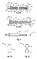
- Fig. 4A illustrates the distal loop portion 410 of the suture-fastening device 400 in a pre-deployed state. Such a state may be referred to as a default state or a stressed state.
- the distal loop portion 410 includes a distal apex 430 as well as a central apex 440.
- the proximal loop portion 420 includes a proximal apex 450.
- the distal loop portion 410 and the proximal loop portion 420 may be formed of a substantially continuous piece of material. Accordingly, the distal loop portion 410 and the proximal loop portion 420 can both include the central apex 440.
- the distal apex 430 and the central apex 440 are separated by a distance referred to as d 3 while the central apex 440 and the proximal apex 450 are separated by a distance referred to as d 4 .
- the distances d 3 and d 4 are provided for ease of illustration only and not by way of limitation. In the default state, distance d 3 between the distal apex 430 and the central apex 440 may be less than distance d 4 between the proximal apex 450 and the central apex 440.
- the distal loop portion 410 and the proximal loop portion 420 are formed from a single continuous piece.
- the suture-fastening device 400 can be cut or removed from a single piece of material as a generally circular or ovular configuration and then be heat set or annealed to transition from the configuration illustrated in Fig. 4A to that of Fig. 4B .
- a change in the size of one of the loop portions results in a change in size of the other loop portion as will be discussed in more detail below.
- Fig. 4B illustrates the suture-fastening device 400 in a state in which proximal loop portion 420 is constricted while the distal loop portion 410 is expanded.
- the distance d 5 between the distal apex 430 and the central apex 440 is greater than the distance d 6 between the proximal apex 450 and the central apex 440.
- Such a state may be generally referred to as an expanded state or unstressed state of the suture-fastening device 400.
- the suture-fastening device 400 may be moved from the default state illustrated in Fig. 4A to the expanded state illustrated in Fig. 4B by applying a force to the proximal loop portion 420.
- a compressive force applied to the proximal loop portion 420 constricts the proximal loop portion 420 to shorten the distance d 6 between the proximal apex 450 and the central apex 440.
- the distal loop portion 410 and the proximal loop portion 420 are part of a continuous piece. Accordingly, as the proximal loop portion 420 is constricted, the distal loop portion 410 expands.
- the deployment device 500 may be used to selectively expand the suture-fastening device 400 and to introduce the suture-fastening device 400 for deployment, as will now be discussed in more detail.
- Fig. 5A illustrates a cross-sectional view of the deployment device 500, according to the invention.
- the deployment device 500 includes a housing 505 having a distal portion 510 and a proximal portion 515.
- the deployment device 500 further includes a first actuator 520 and a second actuator 525.
- the first and second actuators 520, 525 are arranged in a nested fashion within the housing 505 such that the first actuator 520 is located within the housing 505 and the second actuator 525 is nested within the first actuator 520.
- the first actuator 520 includes a first plunger portion 530 and a handle portion 535.
- the second actuator 525 also includes a second plunger portion 540 and a handle portion 545.
- the first plunger portion 530 of the first actuator 520 is configured to house the suture-fastening device 400 before deployment, as illustrated in Fig. 5A , and to cooperate with other parts of the deployment device to move the suture-fastening device 400 to an expanded state and deploy the suture-fastening device 400.
- the housing 505 includes a differentially sized lumen that cooperates with the first and second actuators 520, 525 to move the suture-fastening device 400 to the expanded state.
- the distal portion 510 of the housing 505 may include a necked portion 550 in which the diameter of the lumen defined in the distal portion 510 transitions from a first diameter to a second diameter, the second diameter being smaller than the first diameter
- the first actuator 520 and the second actuator 525 initially move together relative to the housing 505.
- advancing handle portions 535, 545 distally causes the second plunger portion 540 and the first plunger portion 530 to translate distally relative to the housing 505.
- the first plunger portion 530 engages the necked portion 550.
- the engagement between the first plunger portion 530 and the necked portion 550 constricts the second plunger portion 540.
- the constriction of the second plunger portion 540 constricts the proximal loop portion 420.
- constriction of the proximal loop portion 420 causes the distal loop portion 410 to expand.
- the distal portion 510 of the housing 505 includes a slot 555 defined therein.
- the first and second actuators 520, 525 advance as described above to constrict the proximal loop portion 420 and expand the distal loop portion 410, the advancement can bring the then expanded distal loop portion 410 into communication with the slot 555.
- Fig. 5C thus positioning the distal loop portion 410 in an expanded state proximate the slot 555 can allow ends 210, 215 of suture 205 to be threaded through the slot 555 and the distal loop portion 410.
- the deployment device 500 may be moved to place the suture-fastening device 400 at a desired location, such as proximate a puncture. Thereafter, the second actuator 525 may be advanced distally relative to both the first actuator 520 and the housing 505. As the second actuator 525 advances distally, the second actuator 525 drives the suture-fastening device 400 as well until the suture-fastening device 400 is deployed from the distal portion 510 of the deployment device 500, as illustrated in Fig. 5D .
- the suture-fastening device 400 When deployed, the suture-fastening device 400 may move toward the default state described above with reference to Fig. 4A , such that the distal loop portion 410 constricts about the ends 210, 215 of suture 205. As the distal loop portion 410 constricts about the ends 210, 215 of suture 205, the distal loop portion 410 secures the position of the suture 205 relative to a puncture (e.g., P Figs. 2A-2D ), as described above. The ends 210, 215 of suture 205 may then be severed proximally of the suture-fastening device 400.
- a puncture e.g., P Figs. 2A-2D
- the suture-fastening device 400 maintains and/or provides tension in the rest of suture 205 to maintain and/or provide apposition in the puncture in which the suture 205 is deployed. Accordingly, a system, and device have been disclosed herein for maintaining apposition in a suture. The system and device described herein may allow a practitioner to rapidly secure apposition in a suture in a puncture.
- the suture-fastening device may receive the ends of one or more sutures. This again would decrease the time to close a wound. To this point, a configuration has been described in which a looped portion of the device moves between a constricted and expanded state due to spring forces within a resilient material.
- Fig. 6 illustrates an exemplary system 600 for securing a suture that includes a suture-fastening device 700 and a deployment device 800.
- the deployment device 800 is configured to deploy the suture-fastening device 700 to provide and/or maintain tension in a suture to thereby provide and/or maintain apposition in a puncture in tissue.
- Fig. 7A illustrates the exemplary suture-fastening device 700 in a pre-deployed state.
- the suture-fastening device 700 illustrated is formed of a continuous strip. While the suture-fastening device 700 is described as a continuous loop, the suture-fastening device 700 may be formed of several different materials joined to form a closed loop. Further, in additional configurations, the suture-fastening device 700 forms an opened loop. In the state illustrated in Fig. 7A , the suture-fastening device 700 initially forms a single looped portion 705. Through the application and/or removal of forces, the single looped portion 705 can move to a constricted state.
- Fig. 7B illustrates the exemplary suture-fastening device 700 in a deployed state in which the suture-fastening device 700 includes a distal looped portion 710 and a proximal looped portion 720.
- the suture-fastening device 700 may move between the pre-deployed state illustrated in Fig. 7A and the deployed state illustrated in Fig. 7B by a twisting movement.
- the deployed state of the suture-fastening device 700 illustrated in Fig. 7B is the default state.
- a combination of forces may be applied to twist the suture-fastening device 700 to the configuration illustrated in Fig. 7A
- the exemplary deployment device 800 illustrated in more detail in Figs. 8A-8D may be configured to move and/or maintain the suture-fastening device 700 in the pre-deployed state.
- the deployment device 800 includes a housing 805 having a distal portion 810 and a proximal portion 815.
- a lumen is defined in at least the distal portion 810 and can pass through both the distal portion 810 and the proximal portion 815.
- At least the distal portion 810 may be shaped to maintain the suture-deployment device 700 in a pre-deployed state.
- 8B illustrates a partial cross sectional view of the distal portion 810.
- the distal portion 810 may have a major axis 817 and a minor axis 819.
- the major axis 817 may approximately correspond in size to the diameter of the suture-fastening device 700 in the pre-deployed state.
- the minor axis 819 may approximately correspond in size to a thickness of the suture-fastening device 700.
- the distal portion 810 of the housing 805 includes a slot 855 defined therein.
- the suture-fastening device 700 may be loaded into the distal portion 810 of the housing 805 such that the suture-fastening device 700 is in communication with the slot 855.
- the deployment device 800 may facilitate the threading of suture 205 through the suture-fastening device 700 by maintaining the suture-fastening device 700 in an expanded state. With suture 205 thus loaded into the deployment device 800, the deployment device 800 may be moved to a deployment location, such as proximate a puncture that suture 205 have brought into apposition.
- the deployment device 800 further includes an actuator 820.
- the actuator 820 includes a plunger portion 830 and a handle portion 835.
- the plunger portion 830 may drive the suture-fastening device 700 out of the distal portion 810 of the housing 805 to thereby deploy the suture-fastening device 700 with suture 205 threaded therethrough.
- the suture-fastening device 700 returns to the default state.
- the distal loop portion 710 may engage suture 205.
- the distal loop portion 710 may be smaller relative to the proximal loop portion 720.
- the distal loop portion 710 may be of the same size as the distal loop portion 710 in the default state.
- the distal loop portion 710 may be larger than the proximal loop portion 720 in the default state.
- the suture-fastening device 700 moves to a state in which at least one of the looped portions engages a suture to provide and/or maintain tension in the suture and/or to prevent the suture from relaxing.
- the suture-fastening device may be formed from a shape memory material. In other examples, the suture-fastening device may be formed from a bio-resorbable material.
- a suture-fastening device can be used to retain and/or provide apposition for a suture that has been deployed to close an opening in tissue.
- the suture-fastening device includes at least a distal loop portion that moves from a constricted state having a first diameter to a constricted state having a second diameter, the second diameter being less than the first.
- the closure device includes also includes a proximal loop.
- a suture-fastening device is provided in which the diameter of a distal loop decreases while the diameter of a proximal loop increases as the suture-fastening device is deployed.
- Figs. 9A and 9B illustrate another suture-fastening device 900 in accordance with an implementation of the present invention.
- the suture-fastening device 900 has a proximal loop portion 920, a distal loop portion 910, and a central loop portion 930 that are in communication with each other.
- Fig. 9A illustrates the suture-fastening device 900 in a pre-deployed state. Such a state may be referred to as a default state or a stressed state.
- the distal loop portion 910 includes a distal apex 912 as well as a distal central apex 914.
- the proximal loop portion 920 includes a proximal apex 922 and a proximal central apex 924.
- the distal loop portion 910, the proximal loop portion 920, and the central loop portion 930 may be formed of a substantially continuous piece of material.
- the distal apex 912 and the distal central apex 914 are separated by a distance referred to as d 11 while the proximal apex 922 and proximal distal apex 924 are separated by a distance referred to as d 12 , and the distal central apex 914 and proximal central apex 924 are separated by a distance referred to as d 13 .
- the distances d 11 , d 12 , and d 13 are provided for ease of illustration only and not by way of limitation. In the default state, distances d 11 and d 12 may be less than distance d 13 .
- the distal loop portion 910, the proximal loop portion 920, and the central loop portion 930 are formed from a single continuous piece.
- the suture-fastening device 900 can be cut or removed from a single piece of material as a generally circular or ovular configuration and then be heat set or annealed to transition from the configuration illustrated in Fig. 9A to that of Fig. 9B .
- a change in the size of one of loop portions results in a change in size of the other loop portions, as will be discussed in more detail below.
- Fig. 9B illustrates the suture-fastening device 900 in a state in which central loop portion 930 is constricted while the distal loop portion 910 and the proximal loop portion 920 are expanded.
- the distance d 21 between the distal apex 912 and the distal central apex 914 and the distance d 22 between the proximal apex 922 and the proximal central apex 924 are greater than the distance d 23 between the proximal central apex 924 and the distal central apex 914.
- Such a state may be generally referred to as an expanded state or unstressed state of the suture-fastening device 900.
- the suture-fastening device 900 may be moved from the default state illustrated in Fig. 9A to the expanded state illustrated in Fig. 9B by applying a force to the proximal loop portion 920.
- a compressive force applied to the proximal loop portion 920 constricts the proximal loop portion 920 to shorten the distance d 6 between the proximal apex 950 and the central apex 940.
- the distal loop portion 910 and the proximal loop portion 920 are part of a continuous piece. Accordingly, as the proximal loop portion 920 is constricted, the distal loop portion 910 expands.
- the deployment device 500 may be used to selectively expand the suture-fastening device 900 and to introduce the suture-fastening device 900 for deployment, as will now be discussed in more detail.
Landscapes
- Health & Medical Sciences (AREA)
- Life Sciences & Earth Sciences (AREA)
- Surgery (AREA)
- Heart & Thoracic Surgery (AREA)
- Engineering & Computer Science (AREA)
- Biomedical Technology (AREA)
- Nuclear Medicine, Radiotherapy & Molecular Imaging (AREA)
- Medical Informatics (AREA)
- Molecular Biology (AREA)
- Animal Behavior & Ethology (AREA)
- General Health & Medical Sciences (AREA)
- Public Health (AREA)
- Veterinary Medicine (AREA)
- Surgical Instruments (AREA)
Claims (9)
- Vorrichtung (400, 900) zum Befestigen einer Naht, aufweisend:einen Schleifenkörper, wobei der Schleifenkörper einen ersten Schleifenteil (410, 930) hat, der einen ersten Scheitel (450, 914) und einen zweiten Scheitel (440, 924) hat, welche um eine erste Entfernung (d4, d13) beabstandet sind, wobei der Schleifenkörper in einem voraufgebreiteten Zustand und konfiguriert ist, um sich elastisch zu einem aufgebreiteten Zustand zu bewegen, bei dem der erste Scheitel (450, 914) und der zweite Scheitel (440, 924) um eine zweite Entfernung (d6, d23) beabstandet sind, wobei die erste Entfernung (d4, d13) größer ist als die zweite Entfernung (d3, d23), dadurch gekennzeichnet, dass der Schleifenkörper ferner einen zweiten Schleifenteil (410, 920) hat, während er sich in dem voraufgebreiteten Zustand befindet, wobei der zweite Schleifenteil (410, 920) und der erste Schleifenteil (420, 930) operativ derart gekoppelt sind, dass sich der erste Schleifenteil (420, 930) durch Ausstrecken des zweiten Schleifenteils (410, 920) zu dem aufgebreiteten Zustand bewegt.
- Vorrichtung nach Anspruch 1, wobei der Schleifenkörper eine geschlossene Schleife bildet.
- Vorrichtung nach Anspruch 1, wobei der zweite Schleifenteil (410, 920) einen dritten Scheitel (430, 922) aufweist, wobei der dritte Scheitel (430, 922) und der zweite Scheitel (440, 924) in dem voraufgebreiteten Zustand um eine dritte Entfernung (d3, d12) beabstandet sind, und in dem aufgebreiteten Zustand um eine vierte Entfernung (d5, d22), wobei die vierte Entfernung (d5, d22) größer ist als die dritte Entfernung (d3, d12) .
- Vorrichtung nach Anspruch 3, wobei Zusammenrücken des zweiten Schleifenteils (410, 920) den ersten Schleifenteil (420, 930) zu einem voraufgebreiteten Zustand streckt.
- Vorrichtung nach Anspruch 1, wobei die Schleife aus elastischem Material mit Formgedächtnis aufweist.
- System zum Aufrechterhalten der Apposition in einer Naht, wobei das System aufweist:eine Aufbreitvorrichtung (500), wobei die Aufbreitvorrichtung ein Gehäuse (505) und eine Aktuatoreinheit hat, undeine Vorrichtung (400, 900) zum Befestigen einer Naht nach Anspruch 1, wobei die Aufbreitvorrichtung (500) konfiguriert ist, um die Vorrichtung (400, 900) zum Befestigen einer Naht von der voraufgebreiteten Position zu der aufgebreiteten Position zu bewegen.
- System nach Anspruch 6, wobei der zweite Schleifenteil (410, 920) einen dritten Scheitel (430, 922) hat, wobei der zweite und der dritte Scheitel (440, 924; 430, 922) um eine dritte Entfernung (d3, d12) in einem voraufgebreiteten Zustand beabstandet sind, und eine vierte Entfernung (d5, d22) in einem aufgebreiteten Zustand, wobei die vierte Entfernung (d5, d22) größer ist als die dritte Entfernung (d3, d12) und wobei die Aufbreitvorrichtung konfiguriert ist, um selektiv eine Kraft an den zweiten Schleifenteil (410, 920) anzulegen, um die Vorrichtung zum Befestigen der Naht zu der voraufgebreiteten Position zu bewegen.
- System nach Anspruch 6, wobei die Aktuatoreinheit einen ersten Aktuator (520) aufweist, der einen ersten Kolbenteil (530) hat, und einen zweiten Aktuator (525), der einen zweiten Kolbenteil (540) hat, wobei sich der erste Kolbenteil (530) wenigstens teilweise innerhalb des Gehäuses (505) befindet und sich der zweite Kolbenteil (540) wenigstens teilweise innerhalb des ersten Kolbenteils (530) befindet, wobei der erste Kolbenteil (530) konfiguriert ist, um mit dem Gehäuse (505) zusammenzuarbeiten, um die Vorrichtung (400, 900) zum Befestigen einer Naht zu der voraufgebreiteten Position zu bewegen und wobei der zweite Kolbenteil (540) konfiguriert ist, um die Vorrichtung (400, 900) von einem distalen Ende der Aufbreitvorrichtung aufzubreiten.
- System nach Anspruch 8, wobei der erste Aktuator (520) ferner einen ersten Griffteil (535) aufweist, der operativ mit dem ersten Kolbenteil (530) verbunden ist, und einen zweiten Griffteil (545), der operativ mit dem zweiten Kolbenteil (540) verbunden ist, wobei das Betätigen des ersten Griffteils (535) die Vorrichtung (400, 900) zum Befestigen einer Naht zu einer voraufgebreiteten Position bewegt, und wobei das Betätigen des zweiten Griffteils (545) die Vorrichtung (400, 900) zum Befestigen einer Naht von einem distalen Ende der Aufbreitvorrichtung aufbreitet.
Applications Claiming Priority (3)
| Application Number | Priority Date | Filing Date | Title |
|---|---|---|---|
| US1471807P | 2007-12-18 | 2007-12-18 | |
| US12/335,102 US8740938B2 (en) | 2007-12-18 | 2008-12-15 | System, method, and device for closing an opening |
| PCT/US2008/087020 WO2009079513A1 (en) | 2007-12-18 | 2008-12-16 | System, method and device for closing an opening |
Publications (2)
| Publication Number | Publication Date |
|---|---|
| EP2231027A1 EP2231027A1 (de) | 2010-09-29 |
| EP2231027B1 true EP2231027B1 (de) | 2013-04-17 |
Family
ID=40754261
Family Applications (1)
| Application Number | Title | Priority Date | Filing Date |
|---|---|---|---|
| EP08861930.9A Not-in-force EP2231027B1 (de) | 2007-12-18 | 2008-12-16 | System und vorrichtung zum verschliessen einer öffnung |
Country Status (3)
| Country | Link |
|---|---|
| US (1) | US8740938B2 (de) |
| EP (1) | EP2231027B1 (de) |
| WO (1) | WO2009079513A1 (de) |
Families Citing this family (2)
| Publication number | Priority date | Publication date | Assignee | Title |
|---|---|---|---|---|
| US8740938B2 (en) | 2007-12-18 | 2014-06-03 | Abbott Laboratories | System, method, and device for closing an opening |
| US8915933B2 (en) | 2012-11-02 | 2014-12-23 | Medtronic Vascular, Inc. | Suturing device having a retractable distal tip and method for sealing an opening in a blood vessel or other biological structure |
Family Cites Families (9)
| Publication number | Priority date | Publication date | Assignee | Title |
|---|---|---|---|---|
| US5531759A (en) * | 1994-04-29 | 1996-07-02 | Kensey Nash Corporation | System for closing a percutaneous puncture formed by a trocar to prevent tissue at the puncture from herniating |
| JP4136020B2 (ja) * | 1996-04-17 | 2008-08-20 | オリンパス株式会社 | 医療用結紮具 |
| US6409743B1 (en) | 1998-07-08 | 2002-06-25 | Axya Medical, Inc. | Devices and methods for securing sutures and ligatures without knots |
| US6652562B2 (en) | 2001-12-28 | 2003-11-25 | Ethicon, Inc. | Suture anchoring and tensioning device |
| US7048754B2 (en) | 2002-03-01 | 2006-05-23 | Evalve, Inc. | Suture fasteners and methods of use |
| US20060241656A1 (en) | 2002-06-13 | 2006-10-26 | Starksen Niel F | Delivery devices and methods for heart valve repair |
| US7883538B2 (en) * | 2002-06-13 | 2011-02-08 | Guided Delivery Systems Inc. | Methods and devices for termination |
| US7846179B2 (en) | 2005-09-01 | 2010-12-07 | Ovalis, Inc. | Suture-based systems and methods for treating septal defects |
| US8740938B2 (en) | 2007-12-18 | 2014-06-03 | Abbott Laboratories | System, method, and device for closing an opening |
-
2008
- 2008-12-15 US US12/335,102 patent/US8740938B2/en not_active Expired - Fee Related
- 2008-12-16 EP EP08861930.9A patent/EP2231027B1/de not_active Not-in-force
- 2008-12-16 WO PCT/US2008/087020 patent/WO2009079513A1/en not_active Ceased
Also Published As
| Publication number | Publication date |
|---|---|
| US8740938B2 (en) | 2014-06-03 |
| US20090157100A1 (en) | 2009-06-18 |
| WO2009079513A1 (en) | 2009-06-25 |
| EP2231027A1 (de) | 2010-09-29 |
Similar Documents
| Publication | Publication Date | Title |
|---|---|---|
| US8192456B2 (en) | Metal vascular aperture closure device | |
| US20190357900A1 (en) | Suturing Device with Split Arm and Method of Suturing Tissue | |
| EP0673228B1 (de) | Vorrichtung zum nähen einer punktionsstelle in einem blutgefäss | |
| US8398676B2 (en) | Closure device | |
| US6136010A (en) | Articulating suturing device and method | |
| US8398675B2 (en) | Absorbable medical sealing device with retaining assembly having at least two loops | |
| US8303624B2 (en) | Bioabsorbable plug | |
| US8574244B2 (en) | System for closing a puncture in a vessel wall | |
| US10426449B2 (en) | Articulating suturing device with improved actuation and alignment mechanisms | |
| CA2276731C (en) | Hemostatic puncture closure device | |
| JP6506721B2 (ja) | 閉鎖デバイス、展開装置及び閉鎖デバイスの展開方法 | |
| JP2023545137A (ja) | 改善された安全性および管止血を有する血管閉鎖器具 | |
| CN118902516A (zh) | 第一缝合器械和缝合系统 | |
| EP1413255A1 (de) | Resorbiarbare, medizinische Vorrichtung zur chirurgischen Abdichtung | |
| US8740938B2 (en) | System, method, and device for closing an opening | |
| US10772621B2 (en) | Suture management devices, methods, and systems | |
| HK1147930A1 (en) | Closure device, deployment apparatus, and method of deploying a closure device |
Legal Events
| Date | Code | Title | Description |
|---|---|---|---|
| PUAI | Public reference made under article 153(3) epc to a published international application that has entered the european phase |
Free format text: ORIGINAL CODE: 0009012 |
|
| 17P | Request for examination filed |
Effective date: 20100712 |
|
| AK | Designated contracting states |
Kind code of ref document: A1 Designated state(s): AT BE BG CH CY CZ DE DK EE ES FI FR GB GR HR HU IE IS IT LI LT LU LV MC MT NL NO PL PT RO SE SI SK TR |
|
| AX | Request for extension of the european patent |
Extension state: AL BA MK RS |
|
| DAX | Request for extension of the european patent (deleted) | ||
| RTI1 | Title (correction) |
Free format text: SYSTEM AND DEVICE FOR CLOSING AN OPENING |
|
| GRAP | Despatch of communication of intention to grant a patent |
Free format text: ORIGINAL CODE: EPIDOSNIGR1 |
|
| GRAP | Despatch of communication of intention to grant a patent |
Free format text: ORIGINAL CODE: EPIDOSNIGR1 |
|
| GRAS | Grant fee paid |
Free format text: ORIGINAL CODE: EPIDOSNIGR3 |
|
| GRAA | (expected) grant |
Free format text: ORIGINAL CODE: 0009210 |
|
| AK | Designated contracting states |
Kind code of ref document: B1 Designated state(s): AT BE BG CH CY CZ DE DK EE ES FI FR GB GR HR HU IE IS IT LI LT LU LV MC MT NL NO PL PT RO SE SI SK TR |
|
| REG | Reference to a national code |
Ref country code: GB Ref legal event code: FG4D |
|
| REG | Reference to a national code |
Ref country code: CH Ref legal event code: EP |
|
| REG | Reference to a national code |
Ref country code: IE Ref legal event code: FG4D |
|
| REG | Reference to a national code |
Ref country code: AT Ref legal event code: REF Ref document number: 606750 Country of ref document: AT Kind code of ref document: T Effective date: 20130515 |
|
| REG | Reference to a national code |
Ref country code: DE Ref legal event code: R096 Ref document number: 602008023954 Country of ref document: DE Effective date: 20130613 |
|
| REG | Reference to a national code |
Ref country code: NL Ref legal event code: T3 |
|
| REG | Reference to a national code |
Ref country code: AT Ref legal event code: MK05 Ref document number: 606750 Country of ref document: AT Kind code of ref document: T Effective date: 20130417 |
|
| REG | Reference to a national code |
Ref country code: LT Ref legal event code: MG4D |
|
| PG25 | Lapsed in a contracting state [announced via postgrant information from national office to epo] |
Ref country code: GR Free format text: LAPSE BECAUSE OF FAILURE TO SUBMIT A TRANSLATION OF THE DESCRIPTION OR TO PAY THE FEE WITHIN THE PRESCRIBED TIME-LIMIT Effective date: 20130718 Ref country code: ES Free format text: LAPSE BECAUSE OF FAILURE TO SUBMIT A TRANSLATION OF THE DESCRIPTION OR TO PAY THE FEE WITHIN THE PRESCRIBED TIME-LIMIT Effective date: 20130728 Ref country code: SI Free format text: LAPSE BECAUSE OF FAILURE TO SUBMIT A TRANSLATION OF THE DESCRIPTION OR TO PAY THE FEE WITHIN THE PRESCRIBED TIME-LIMIT Effective date: 20130417 Ref country code: IS Free format text: LAPSE BECAUSE OF FAILURE TO SUBMIT A TRANSLATION OF THE DESCRIPTION OR TO PAY THE FEE WITHIN THE PRESCRIBED TIME-LIMIT Effective date: 20130817 Ref country code: LT Free format text: LAPSE BECAUSE OF FAILURE TO SUBMIT A TRANSLATION OF THE DESCRIPTION OR TO PAY THE FEE WITHIN THE PRESCRIBED TIME-LIMIT Effective date: 20130417 Ref country code: SE Free format text: LAPSE BECAUSE OF FAILURE TO SUBMIT A TRANSLATION OF THE DESCRIPTION OR TO PAY THE FEE WITHIN THE PRESCRIBED TIME-LIMIT Effective date: 20130417 Ref country code: PT Free format text: LAPSE BECAUSE OF FAILURE TO SUBMIT A TRANSLATION OF THE DESCRIPTION OR TO PAY THE FEE WITHIN THE PRESCRIBED TIME-LIMIT Effective date: 20130819 Ref country code: AT Free format text: LAPSE BECAUSE OF FAILURE TO SUBMIT A TRANSLATION OF THE DESCRIPTION OR TO PAY THE FEE WITHIN THE PRESCRIBED TIME-LIMIT Effective date: 20130417 Ref country code: NO Free format text: LAPSE BECAUSE OF FAILURE TO SUBMIT A TRANSLATION OF THE DESCRIPTION OR TO PAY THE FEE WITHIN THE PRESCRIBED TIME-LIMIT Effective date: 20130717 Ref country code: FI Free format text: LAPSE BECAUSE OF FAILURE TO SUBMIT A TRANSLATION OF THE DESCRIPTION OR TO PAY THE FEE WITHIN THE PRESCRIBED TIME-LIMIT Effective date: 20130417 Ref country code: BE Free format text: LAPSE BECAUSE OF FAILURE TO SUBMIT A TRANSLATION OF THE DESCRIPTION OR TO PAY THE FEE WITHIN THE PRESCRIBED TIME-LIMIT Effective date: 20130417 |
|
| PG25 | Lapsed in a contracting state [announced via postgrant information from national office to epo] |
Ref country code: HR Free format text: LAPSE BECAUSE OF FAILURE TO SUBMIT A TRANSLATION OF THE DESCRIPTION OR TO PAY THE FEE WITHIN THE PRESCRIBED TIME-LIMIT Effective date: 20130417 Ref country code: CY Free format text: LAPSE BECAUSE OF FAILURE TO SUBMIT A TRANSLATION OF THE DESCRIPTION OR TO PAY THE FEE WITHIN THE PRESCRIBED TIME-LIMIT Effective date: 20130417 Ref country code: BG Free format text: LAPSE BECAUSE OF FAILURE TO SUBMIT A TRANSLATION OF THE DESCRIPTION OR TO PAY THE FEE WITHIN THE PRESCRIBED TIME-LIMIT Effective date: 20130717 Ref country code: PL Free format text: LAPSE BECAUSE OF FAILURE TO SUBMIT A TRANSLATION OF THE DESCRIPTION OR TO PAY THE FEE WITHIN THE PRESCRIBED TIME-LIMIT Effective date: 20130417 Ref country code: LV Free format text: LAPSE BECAUSE OF FAILURE TO SUBMIT A TRANSLATION OF THE DESCRIPTION OR TO PAY THE FEE WITHIN THE PRESCRIBED TIME-LIMIT Effective date: 20130417 |
|
| PG25 | Lapsed in a contracting state [announced via postgrant information from national office to epo] |
Ref country code: CZ Free format text: LAPSE BECAUSE OF FAILURE TO SUBMIT A TRANSLATION OF THE DESCRIPTION OR TO PAY THE FEE WITHIN THE PRESCRIBED TIME-LIMIT Effective date: 20130417 Ref country code: DK Free format text: LAPSE BECAUSE OF FAILURE TO SUBMIT A TRANSLATION OF THE DESCRIPTION OR TO PAY THE FEE WITHIN THE PRESCRIBED TIME-LIMIT Effective date: 20130417 Ref country code: EE Free format text: LAPSE BECAUSE OF FAILURE TO SUBMIT A TRANSLATION OF THE DESCRIPTION OR TO PAY THE FEE WITHIN THE PRESCRIBED TIME-LIMIT Effective date: 20130417 Ref country code: SK Free format text: LAPSE BECAUSE OF FAILURE TO SUBMIT A TRANSLATION OF THE DESCRIPTION OR TO PAY THE FEE WITHIN THE PRESCRIBED TIME-LIMIT Effective date: 20130417 |
|
| PLBE | No opposition filed within time limit |
Free format text: ORIGINAL CODE: 0009261 |
|
| STAA | Information on the status of an ep patent application or granted ep patent |
Free format text: STATUS: NO OPPOSITION FILED WITHIN TIME LIMIT |
|
| PG25 | Lapsed in a contracting state [announced via postgrant information from national office to epo] |
Ref country code: RO Free format text: LAPSE BECAUSE OF FAILURE TO SUBMIT A TRANSLATION OF THE DESCRIPTION OR TO PAY THE FEE WITHIN THE PRESCRIBED TIME-LIMIT Effective date: 20130417 Ref country code: IT Free format text: LAPSE BECAUSE OF FAILURE TO SUBMIT A TRANSLATION OF THE DESCRIPTION OR TO PAY THE FEE WITHIN THE PRESCRIBED TIME-LIMIT Effective date: 20130417 |
|
| 26N | No opposition filed |
Effective date: 20140120 |
|
| REG | Reference to a national code |
Ref country code: DE Ref legal event code: R097 Ref document number: 602008023954 Country of ref document: DE Effective date: 20140120 |
|
| REG | Reference to a national code |
Ref country code: CH Ref legal event code: PL |
|
| GBPC | Gb: european patent ceased through non-payment of renewal fee |
Effective date: 20131216 |
|
| PG25 | Lapsed in a contracting state [announced via postgrant information from national office to epo] |
Ref country code: MC Free format text: LAPSE BECAUSE OF FAILURE TO SUBMIT A TRANSLATION OF THE DESCRIPTION OR TO PAY THE FEE WITHIN THE PRESCRIBED TIME-LIMIT Effective date: 20130417 Ref country code: LU Free format text: LAPSE BECAUSE OF FAILURE TO SUBMIT A TRANSLATION OF THE DESCRIPTION OR TO PAY THE FEE WITHIN THE PRESCRIBED TIME-LIMIT Effective date: 20131216 |
|
| REG | Reference to a national code |
Ref country code: FR Ref legal event code: ST Effective date: 20140829 |
|
| PG25 | Lapsed in a contracting state [announced via postgrant information from national office to epo] |
Ref country code: CH Free format text: LAPSE BECAUSE OF NON-PAYMENT OF DUE FEES Effective date: 20131231 Ref country code: LI Free format text: LAPSE BECAUSE OF NON-PAYMENT OF DUE FEES Effective date: 20131231 |
|
| PG25 | Lapsed in a contracting state [announced via postgrant information from national office to epo] |
Ref country code: GB Free format text: LAPSE BECAUSE OF NON-PAYMENT OF DUE FEES Effective date: 20131216 Ref country code: FR Free format text: LAPSE BECAUSE OF NON-PAYMENT OF DUE FEES Effective date: 20131231 |
|
| PG25 | Lapsed in a contracting state [announced via postgrant information from national office to epo] |
Ref country code: TR Free format text: LAPSE BECAUSE OF FAILURE TO SUBMIT A TRANSLATION OF THE DESCRIPTION OR TO PAY THE FEE WITHIN THE PRESCRIBED TIME-LIMIT Effective date: 20130417 |
|
| PG25 | Lapsed in a contracting state [announced via postgrant information from national office to epo] |
Ref country code: HU Free format text: LAPSE BECAUSE OF FAILURE TO SUBMIT A TRANSLATION OF THE DESCRIPTION OR TO PAY THE FEE WITHIN THE PRESCRIBED TIME-LIMIT; INVALID AB INITIO Effective date: 20081216 |
|
| PG25 | Lapsed in a contracting state [announced via postgrant information from national office to epo] |
Ref country code: MT Free format text: LAPSE BECAUSE OF FAILURE TO SUBMIT A TRANSLATION OF THE DESCRIPTION OR TO PAY THE FEE WITHIN THE PRESCRIBED TIME-LIMIT Effective date: 20130417 |
|
| PGFP | Annual fee paid to national office [announced via postgrant information from national office to epo] |
Ref country code: NL Payment date: 20171212 Year of fee payment: 10 |
|
| PGFP | Annual fee paid to national office [announced via postgrant information from national office to epo] |
Ref country code: IE Payment date: 20171128 Year of fee payment: 10 |
|
| PGFP | Annual fee paid to national office [announced via postgrant information from national office to epo] |
Ref country code: DE Payment date: 20171221 Year of fee payment: 10 |
|
| REG | Reference to a national code |
Ref country code: DE Ref legal event code: R119 Ref document number: 602008023954 Country of ref document: DE |
|
| REG | Reference to a national code |
Ref country code: NL Ref legal event code: MM Effective date: 20190101 |
|
| REG | Reference to a national code |
Ref country code: IE Ref legal event code: MM4A |
|
| PG25 | Lapsed in a contracting state [announced via postgrant information from national office to epo] |
Ref country code: NL Free format text: LAPSE BECAUSE OF NON-PAYMENT OF DUE FEES Effective date: 20190101 |
|
| PG25 | Lapsed in a contracting state [announced via postgrant information from national office to epo] |
Ref country code: DE Free format text: LAPSE BECAUSE OF NON-PAYMENT OF DUE FEES Effective date: 20190702 Ref country code: IE Free format text: LAPSE BECAUSE OF NON-PAYMENT OF DUE FEES Effective date: 20181216 |
|
| P01 | Opt-out of the competence of the unified patent court (upc) registered |
Effective date: 20230530 |