EP2230813B1 - A method and node for establishing a network connection by way of a connectionless transport layer protocol - Google Patents
A method and node for establishing a network connection by way of a connectionless transport layer protocol Download PDFInfo
- Publication number
- EP2230813B1 EP2230813B1 EP10156613A EP10156613A EP2230813B1 EP 2230813 B1 EP2230813 B1 EP 2230813B1 EP 10156613 A EP10156613 A EP 10156613A EP 10156613 A EP10156613 A EP 10156613A EP 2230813 B1 EP2230813 B1 EP 2230813B1
- Authority
- EP
- European Patent Office
- Prior art keywords
- node
- data packets
- connection
- data packet
- nodes
- Prior art date
- Legal status (The legal status is an assumption and is not a legal conclusion. Google has not performed a legal analysis and makes no representation as to the accuracy of the status listed.)
- Active
Links
Images



Classifications
-
- H—ELECTRICITY
- H04—ELECTRIC COMMUNICATION TECHNIQUE
- H04L—TRANSMISSION OF DIGITAL INFORMATION, e.g. TELEGRAPHIC COMMUNICATION
- H04L69/00—Network arrangements, protocols or services independent of the application payload and not provided for in the other groups of this subclass
- H04L69/16—Implementation or adaptation of Internet protocol [IP], of transmission control protocol [TCP] or of user datagram protocol [UDP]
-
- H—ELECTRICITY
- H04—ELECTRIC COMMUNICATION TECHNIQUE
- H04L—TRANSMISSION OF DIGITAL INFORMATION, e.g. TELEGRAPHIC COMMUNICATION
- H04L45/00—Routing or path finding of packets in data switching networks
- H04L45/38—Flow based routing
-
- H—ELECTRICITY
- H04—ELECTRIC COMMUNICATION TECHNIQUE
- H04L—TRANSMISSION OF DIGITAL INFORMATION, e.g. TELEGRAPHIC COMMUNICATION
- H04L69/00—Network arrangements, protocols or services independent of the application payload and not provided for in the other groups of this subclass
- H04L69/16—Implementation or adaptation of Internet protocol [IP], of transmission control protocol [TCP] or of user datagram protocol [UDP]
- H04L69/161—Implementation details of TCP/IP or UDP/IP stack architecture; Specification of modified or new header fields
- H04L69/162—Implementation details of TCP/IP or UDP/IP stack architecture; Specification of modified or new header fields involving adaptations of sockets based mechanisms
-
- H—ELECTRICITY
- H04—ELECTRIC COMMUNICATION TECHNIQUE
- H04L—TRANSMISSION OF DIGITAL INFORMATION, e.g. TELEGRAPHIC COMMUNICATION
- H04L69/00—Network arrangements, protocols or services independent of the application payload and not provided for in the other groups of this subclass
- H04L69/16—Implementation or adaptation of Internet protocol [IP], of transmission control protocol [TCP] or of user datagram protocol [UDP]
- H04L69/164—Adaptation or special uses of UDP protocol
-
- H—ELECTRICITY
- H04—ELECTRIC COMMUNICATION TECHNIQUE
- H04L—TRANSMISSION OF DIGITAL INFORMATION, e.g. TELEGRAPHIC COMMUNICATION
- H04L69/00—Network arrangements, protocols or services independent of the application payload and not provided for in the other groups of this subclass
- H04L69/22—Parsing or analysis of headers
-
- H—ELECTRICITY
- H04—ELECTRIC COMMUNICATION TECHNIQUE
- H04L—TRANSMISSION OF DIGITAL INFORMATION, e.g. TELEGRAPHIC COMMUNICATION
- H04L12/00—Data switching networks
- H04L12/54—Store-and-forward switching systems
- H04L12/56—Packet switching systems
- H04L12/5601—Transfer mode dependent, e.g. ATM
- H04L2012/5638—Services, e.g. multimedia, GOS, QOS
- H04L2012/5645—Connectionless
-
- H—ELECTRICITY
- H04—ELECTRIC COMMUNICATION TECHNIQUE
- H04L—TRANSMISSION OF DIGITAL INFORMATION, e.g. TELEGRAPHIC COMMUNICATION
- H04L47/00—Traffic control in data switching networks
- H04L47/10—Flow control; Congestion control
-
- H—ELECTRICITY
- H04—ELECTRIC COMMUNICATION TECHNIQUE
- H04L—TRANSMISSION OF DIGITAL INFORMATION, e.g. TELEGRAPHIC COMMUNICATION
- H04L47/00—Traffic control in data switching networks
- H04L47/10—Flow control; Congestion control
- H04L47/24—Traffic characterised by specific attributes, e.g. priority or QoS
- H04L47/2483—Traffic characterised by specific attributes, e.g. priority or QoS involving identification of individual flows
Definitions
- the present invention relates to a method and node for establishing a network connection by way of a connectionless transport layer protocol.
- the Internet has become an important communication network for transporting data of many kinds, including textual, audio, and visual data, between distinct nodes of the network.
- the transfer of this data within the Internet is facilitated by a "stack" of architectural "layers", with each layer providing a corresponding type of functionality required of the network to transport the data.
- Each of these layers at least roughly corresponds to one or more of the seven layers of the Open Systems Interconnection (OSI) Reference Model, which identifies seven different layers, namely the physical layer, the data link layer, the network layer, the transport layer, the session layer, the presentation layer, and the application layer, in ascending order. Only one of these layers represents the actual physical network connection. The remaining layers describe the various types of data and associated control information being generated and transferred within the network.
- OSI Open Systems Interconnection
- TCP Transmission Control Protocol
- UDP User Datagram Protocol
- TCP provides for logical connections to be established between two end nodes of the network for subsequent data transfer therebetween.
- TCP provides a data packet acknowledgement, timeout, and retransmission mechanism, as well as a packet sequencing facility, to protect against data loss.
- UDP does not provide an acknowledgement, timeout, or retransmission mechanism, does not explicitly facilitate data packet sequencing, and does not establish a logical connection between two communicating network nodes. Due to its lower overhead, UDP is often utilized in situations in which data loss is less important than any additional delay that may be incurred by using TCP for data packet transmission. By contrast, TCP is typically employed in scenarios in which data reliability and integrity are important considerations.
- API application programming interface
- BSD Berkeley Software Distribution
- US-A-2008/0075048 describes a socket module on a wireless communication device which establishes and maintains open UDP sockets with a remote server over a wireless communication network and manages the dormancy state of the radio link to the wireless communication network.
- the state of the radio link may be either active or dormant and the socket module keeps the UDP socket open even when the state of the radio link is dormant, thereby reducing setup time for communications between the wireless device and the remote server.
- the socket module is configured to maintain multiple open sockets for a plurality of applications that may run on the wireless device and thereby operate as a passive server for such applications on the wireless device.
- US-A-2003/0115357 describes a socket migration architecture for migrating a communication socket among host devices and having a plurality of migrateable sockets each operating in conjunction with one of a plurality of applications on a plurality of host devices.
- Each of the applications may utilize a respective migrateable socket to establish peer-to-peer communications with at least one other application.
- the migrateable sockets may form an association link between migrateable sockets operating on different host devices.
- at least one association link established prior to the migration may be used to reestablished peer-to-peer communications as part of the migration event.
- US-A-2008/0281976 describes an apparatus including a plurality ofUDP ports capable of receiving UDP messages and a message generator to generate a request message to be transmitted to remote endpoints connected over a network via a connectionless diagram protocol.
- the request message includes a header section having data identifying a plurality of reply-to addresses corresponding to the UDP ports.
- the requesting device and the responding devices will have an understanding that each responding device can send their response messages to "any" of reply-to addresses listed in the request message transmitted by the requesting device.
- Each responding device which receives a request message randomly chooses which of the reply-to-addresses to respond to.
- the present invention seeks to provide a method to establish a network connection which, whilst having reliability and integrity, keeps its overhead low.
- a method of establishing a network connection between first and second nodes by way of a connectionless transport layer communication protocol utilising data packets which each comprise a header and a payload formatted according to the connectionless protocol, the connectionless protocol payload of each data packet comprising a separate header having a first port indicator for the first node and a second port indicator for the second node; and the method comprising exchanging data packets between the first and second nodes, identifying at each node that a connection between the first and second nodes is to be established by the presence of the first and second port indicators in the data packets exchanged between the first and second nodes, and establishing a connection between the first and second nodes in response to the exchange and identifying steps.
- the separate header of at least one of the data packets includes an indication that a connection between the first and second nodes is to be established, and a connection between the two nodes is established upon receipt at one of the nodes of said indication.
- the separate header of at least one of the data packets includes a first session identifier for the first node and a second session identifier for the second node, and the method further comprises utilising at least one of the first session identifier and the second session identifier to verify whether the data packets belong to a current session.
- the method may further comprise discarding data packets identified as not belonging to the current session.
- exchanging data packets comprises transmitting a first data packet from the first node to the second node, receiving the first data packet at the second node; and transmitting a second data packet from the second node to the first node.
- the method further comprises awaiting the second data packet at the first node; and retransmitting the first data packet from the first node to the second node if the second data packet is not received at the first node within a first predetermined time period after the transmitting of the first data packet.
- the separate header of the first data pocket may include an indication to establish a connection with the second node, and the separate header of the second data packet may include an indication of an acknowledgment of the indication to establish a connection of the first data packet.
- connectionless protocol comprises a user datagram protocol.
- the present invention also extends to node for a communication network comprising a communication interface arranged to exchange data packets with another node of the network by way of a connectionless transport layer communication protocol; and control circuitry for generating data packets which each comprise a header and a payload formatted according to the connectionless protocol, the connectionless protocol payload of each data packet comprising a separate header having a first port indicator for the first node and a second port indicator for the second node; wherein the control circuitry is arranged to exchange data packets, by way of the communication interface, with the other node; wherein the control circuitry is arranged to identify that a connection of the node is to be established with the other node by identifying the presence of the first and second port indicators; and wherein the control circuitry is arranged to establish the connection between the node and the other node in response to the exchange and identification.
- control circuitry is arranged to generate data packets and to transmit the data packets to the other node, and wherein the control circuitry is arranged to receive data packets from the other node whereby data packets are exchanged.
- connectionless protocol comprises a user datagram protocol.
- Fig. 1 shows a simplified block diagram of a communication network 100 in which a first node 102 and a second node 104 may establish a logical connection 110 therebetween for the transfer of data.
- a connection 110 is a logical association of the two nodes 102, 104 with each other for the purpose of transmitting and receiving data therebetween.
- the connection 110 may facilitate error correction and other worthwhile mechanisms for the data being transferred.
- the network 100 may be any communication network over which digital data may be carried or transferred, including a local area network (LAN), or a wide area network (WAN), such as the Internet.
- LAN local area network
- WAN wide area network
- the Figure implies a direct coupling between the nodes 102, 104, other communication devices, such as routers, switches, firewalls, and the like, may be used to communicatively couple the nodes 102, 104 together in various arrangements.
- the data being transmitted and received may include video data, audio data, textual data, numeric data, or any other form of data.
- Fig. 2 is a flow diagram of a method 200 for establishing the connection 110 between the first node 102 and the second node 104 via a connectionless transport layer communication protocol.
- a connectionless transport layer communication protocol facilitates a basic mechanism for the transmission of "datagrams" without explicitly establishing a connection between the source and destination nodes involved beforehand.
- protection mechanisms such as retransmission, error correction, sequencing of datagrams, and the like, are not implemented in the connectionless protocol in order to reduce overhead and increase data throughput.
- UDP User Datagram Protocol
- TCP Transmission Control Protocol
- IP Internet Protocol
- a plurality of data packets 106 are exchanged between the first node 102 and the second node 104 of the network 100 (operation 202).
- the data packets 106 transmitted from the first node 102 to the second node 104 may be transmitted over a different path through the network 100 to those packets 106 traveling in the opposite direction.
- Each of the data packets 106 includes a header and a payload formatted according to the connectionless transport layer communication protocol.
- a data packet header is control and/or status information related to the payload residing in the data packet, and is currently positioned at the end of the data packet 106, although other locations within the data packet are possible.
- connectionless protocol payload includes a separate header including a first port indicator for the first node 102 and a second port indicator for the second node 104.
- a port number may be any indicator or value designating a logical input or pathway of a node identified with a particular set of communications.
- the separate header of at least one of the data packets includes an indication to establish a connection 110 between the first node 102 and the second node 104.
- the first node 102 and the second node 104 establish the connection 110 between the first node 102 and the second node 104, wherein the first port indicator and the second port indicator are associated with the established connection 110 (operation 204).
- a computer-readable storage medium may have encoded thereon instructions for a processor or other control circuitry to direct a device to implement the method 200.
- Use of the method 200 may thus allow the nodes 102, 104 to establish a connection therebetween by way of a standard connectionless protocol, such as UDP, thereby circumventing a standard connection protocol, such as TCP, whilst still employing the network layer IP standard logic commonly provided in many communication devices.
- a communication protocol layer developed for a particular communication environment such as the streaming of video data packets across the network 100, may be employed in lieu of the TCP protocol by employing the connectionless UDP protocol and underlying network layers as a data transmission mechanism.
- the new transport layer may address communication situations associated with the nature of the data being transferred, the type of communication links being employed, and other characteristics that are not handled efficiently by a more standardized transport layer connection protocol.
- Fig. 3 is a block diagram of a particular communication software hierarchy 300 which may be implemented within a network node.
- the hierarchy 300 when implemented within each of two network nodes, facilitates the establishment of a connection between the nodes over a connectionless transport layer communication protocol. Whilst the following discussion focuses on the specific hierarchy 300 of Fig. 3 as a software platform by which the connection may be established, other software architectural configurations may be employed to similar effect in other implementations.
- the software hierarchy 300 includes an application 302, a "sockets" module 304, a reliability module 306, a connectivity module 308, and a transport/network layer protocol stack 310, such as a TCP/IP stack, including support for a connectionless transport layer protocol, such as UDP.
- the application 302 may be any application-level software requiring access to a communication network.
- the application 302 may be an audio/video stream source and/or display application, thus necessitating access to the communication network for the transmission and/or reception of audio/video data.
- an audio/video destination such as a computer system, a personal digital assistant (PDA), or a mobile communication device
- a video source node such as a Slingbox by Sling Media, Inc.
- the destination node may stream video from the set-top box via the source node over the network.
- the source node may be viewed as a server node, while the destination node may be regarded as a client-node, with both the server node and the client node each separately implementing the software hierarchy 300 of Fig. 3 .
- the sockets module 304 provides an application programming interface (API) through which the application 302 of the client or server device may access the network, including the establishment of connections and transfer of data over such connections. Such an interface is often facilitated by way of a set of function calls provided by the sockets module 304, such as those shown in Fig. 4 , and explained in greater detail below.
- a "socket" is an endpoint of a communication path through the network defined by a node address (such as an IP address) and a port number.
- the sockets module 304 allows the application 302 to create one or more such sockets, request a connection to another node using the socket, transmit and/or receive data via the socket, free the socket, and other applicable tasks. Accordingly, the sockets module 304 implements many of the operations discussed below concerning establishment and termination of one or more connections by way of a packet-based handshaking protocol using a connectionless transport layer protocol, retransmission of lost handshaking packets, and other functionality.
- the sockets module 304 accesses the reliability module 306 to facilitate various protection mechanisms for the user data being transferred over an established connection between network nodes.
- Such mechanisms may include, but are not limited to, sequencing of the user data packets to facilitate their proper ordering at the receiving node, acknowledgment (or non-acknowledgment) and retransmission of lost user data packets, and other functionality not provided by a connectionless transport layer protocol, such as UDP.
- the reliability module 306 may implement such protections as a replacement for the standard TCP layer.
- the sockets module 304 may further interface with a connection module 308, which may facilitate the creation of "tunnels” or other mechanisms for maintaining a viable communication path between two network nodes.
- the sockets module 304 also communicates with the standardized transport/network protocol stack 310, such as a TCP/IP stack which incorporates a connectionless transport layer protocol, such as UDP.
- the sockets module 304 employs the UDP portion of the TCP/IP stack, thus circumventing TCP whilst implementing the connection handshake mechanism. Sequencing and retransmission capabilities supplied by the reliability module 306 may also be implemented in lieu of the corresponding functionality normally provided in TCP.
- the functionality provided by the sockets module 304, the reliability module 306, and the connectivity module 308 may be tailored to address various aspects of specific communication environments more efficiently than that provided by TCP.
- the application 302 communicates with the sockets module 304 by way of function calls 320 without having to engage in the specific details of the other modules 306, 308, 310 provided in the software hierarchy 300.
- the sockets module 304 handles the required communications with the other modules 306, 308, 310, primarily in response to the function calls 320.
- Fig. 4 provides a listing of possible function calls 320 presented to the application 302, some of which are briefly described below.
- sInit() and sclose() allocate and release, respectively, the various structures and overall context for the sockets used for network communications.
- the functions sCreateSocket() and sclosesocket() facilitate the creation and deletion of a specific socket employed in a communication connection. A created socket may then be bound to a particular IP address and port by way of the sBind() function.
- sListen() a connection using an existing socket is accomplished by way of one or more of the sListen(), sConnent(), and sAccept() functions, based on whether the application 302 is acting as a client (and, thus, is initiating a connection) or a server (which receives and acknowledges such an initiation).
- data may be sent to and received from another node by way of the reliability module 306 via the sSend() and sRecv() functions, which allow the application to read from and write to data buffers supplied by the reliability module 306.
- Other functions may provide access to control and status data, as well as other aspects, of the sockets module 304.
- the sockets module 304 may handle a number of asynchronous events, such as those initiated by communication activity of another node on the network. For example, the sockets module 304 may respond to attempts by the other node to establish a new connection, terminate an existing connection, or to transmit data to the node employing the sockets module 304. Such events may be serviced by way of interrupt control, polling, or other asynchronous event-handling means.
- Fig. 5 provides a simplified block diagram of a node 500 of a communication network.
- the node 500 includes a communication interface 502 and control circuitry 504.
- the communication interface 502 is configured to transmit and receive data packets with another node of the network.
- the communication interface 502 is an interface configured to communicate over an IP interface implemented over a wired or wireless link/physical layer. Examples of such layers include Ethernet, Wi-Fi (e.g., IEEE 802.11a/b/g/n), digital subscriber line (DSL), cable modem, and others. Network layers other than IP may be employed in other arrangements.
- the communication interface 502 may be implemented as a network interface card (NIC), circuitry located on a computer system motherboard, or via other circuit means.
- NIC network interface card
- the control circuitry 504 is configured to generate and transmit data packets via the communication interface 502 to one or more other nodes, as well as to receive and process data packets from those nodes by way of the interface 502. The structure and use of those packets is discussed below.
- the control circuitry 504 may include one or more processors, such as a microprocessor, microcontroller, or digital signal processor (DSP), arranged to execute instructions directing the processor to perform the functions and facilitate the communication discussed in greater detail below.
- the control circuitry 502 may also include memory or data storage containing the instructions.
- the control circuitry 502 may be strictly hardware-based logic, or may include a combination of hardware, firmware, and/or software elements.
- Fig. 6 is a communication diagram 600 exemplifying various data packets transmitted by a first node 602 and a second node 604 to establish a connection, transfer data, and then terminate the connection.
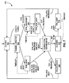
- Fig. 7 is a state diagram 700 depicting the various possible states and associated state transitions each of the nodes 602, 604 encounters during the establishment and termination of a connection.
- the first node 602 operates as a client node
- the second node 604 is a server node.
- the second node 604 is arranged to receive connection requests prior to the transmission of such a request by the first node 602.
- One example of such an arrangement may be a user computer client requesting an audio/video data stream from a Slingbox server, which delivers audio/video sourced by a set-top box over the network to the client computer.
- a Slingbox server which delivers audio/video sourced by a set-top box over the network to the client computer.
- other communication environments involving different forms of data may benefit from the described formats.
- both the first (client) node 602 and the second (server) node 604 are presumed to reside in the CLOSED state 702, indicating that no connection is current established between the nodes 602, 604.
- each of the nodes 602, 604 employs their respective connectivity module 308 to create a tunnel or other communication path via the transport/network layer 310, thus placing both nodes 602, 604 into the TUNNEL_CREATED state 704.
- the tunnel or path is identified by way of a device address, such as an IP address, for each of the nodes 602, 604.
- the tunnel may be identified by way of a "finder ID" for at least one of the nodes 602, 604.
- the finder ID may be a logical identifier associated with one of the nodes 602, 604 that may be used to determine the IP address for that node 602, 604 by way of a look-up table.
- the first node 602 transmits a SYN data packet 610, thus initiating a handshake with the second node 604 to establish a connection.
- the SYN data packet 610 as well as all subsequent data packets involving the same connection, identify a local port indicator associated with the first node 602 and a remote port indicator associated with the second node 604.
- Each port indicator may be selected by the application 302 of the node 602, 604, or may be generated randomly or by other means by the sockets module 304.
- the first node 602 assumes the SYN_SENT state 706 and awaits an affirmative response from the second node 604.
- the application 302 initiates the handshake by way of the sConnect() function call described earlier.
- the second node 604 transitions to the SYN_RECEIVED state 708.
- the second node 604 employs the sListen() function to enable its sockets module 304 prior to transmission of the SYN data packet 610 to receive the SYN data packet 610. Thereafter, the second node 604 transfers a SYN_ACK data packet 612 to the first node 602 to continue the handshake, and assumes the SYN_ACK_SENT state 710.
- the sockets module 304 notifies the application 302, which in turn calls the sAccept() module to transmit the SYN_ACK data packet 612.
- the first node 602 may implement a timeout period that is initiated after the SYN data packet 610 is transmitted. If the first node 602 then does not receive the SYN_ACK data packet 612 during the timeout period, the first node 602 may return to the TUNNEL_CREATED state 704, retransmit the SYN data packet 610, and transition again to the SYN_SENT state 706.
- the first node 602 may retransmit the SYN data packet 610 several times up to some maximum number while a corresponding SYN_ACK data packet 612 is not received.
- the time period may be different for two or more of the possible retransmissions of the SYN data packet 610, with the time periods possibly increasing or decreasing for each successive retransmission.
- the first node 602 Presuming that the first node 602 successfully received the SYN_ACK data packet 612, the first node 602 would then complete the handshake by transmitting an ACK data packet 614 to the second node 604 to confirm receipt of the SYN_ACK data packet 612, and transition from the SYN_SENT state 706 to the CONNECTION_ESTABLISHED state 714.
- the second node 604 upon receiving the ACK data packet 614, the second node 604 also assumes the CONNECTION_ESTABLISHED state 714, thus placing both nodes 602, 604 in agreement that a communication connection has been established therebetween.
- the second node 604 may implement error recovery in the case of a missing or defective SYN_ACK data packet 612 or ACK data packet 614, either of which may prevent the second node 604 from properly receiving the ACK packet 614. More specifically, the second node 604 may implement a timeout period that is initiated after the second node 604 transmits the SYN_ACK data packet 612.
- the second node 604 may then return to the SYN_RECEIVED state 708, retransmit the SYN_ACK data packet 612, and again assume the SYN_ACK_SENT state 710.
- the second node 604 may retransmit the SYN_ACK data packet 612 a number of times up to some maximum value while a corresponding ACK data packet 614 is not received.
- the time period may be different for two or more of the possible retransmissions of the SYN_ACK data packet 612, with the time periods possibly increasing or decreasing for each successive retransmission.
- the number of transmissions, and the associated time periods may be different from those used for retransmission of the SYN data packet 610.
- both of the nodes 602, 604 operate within the CONNECTION_ESTABLISHED state 714.
- the connection is identified in the nodes 602, 604 by way of the port indicators associated with each of the nodes 602, 604.
- transfer of user data packets 620 such as data packets containing audio/video data, as mentioned above, may then occur between the nodes 602, 604.
- the first node 602 since the first node 602 has already received the SYN_ACK data packet 612 from the second node 604, and since the mechanism shown in Fig.
- the first node 602 may be configured to transmit an ACK data packet 614 in response to receiving a SYN_ACK data packet 612 from the second node 604 after the first node 602 has already attained the CONNECTION_ESTABLISHED state 714.
- the sockets module 304 facilitates the sending and receiving of data by way of the sSend() and sRecv() functions, which involve use of the reliability module 306 for sending and receiving the data in data packets under a scheme which may include sequencing, positive and/or negative acknowledge, and other protection mechanisms, as mentioned above.
- node 602, 604 may begin terminating or closing the connection. Presuming the application 302 of the first node 602 has made this determination, the application 302 may initiate the termination of the connection by first using the sCloseSocket() function call, which in turn causes the first node 602 to enter the CLOSING state 716, initiate a FIN data packet 630, and transitions the first node 602 to the FIN_SENT state 718.
- the second node 604 Presuming the second node 602 successfully receives the FIN data packet 630, the second node 604 assumes the FIN_RECEIVED state 720, sends a FIN_ACK data packet 632 to the first node 602, and arrives at the CLOSED state 702, indicating that the connection has been terminated. Once the first node 602 receives the FIN_ACK data packet 632, the first node 602 also enters the CLOSED state 702, thus confirming that the connection is terminated.
- the first node 602 While in the FIN_SENT state 718 after issuing the FIN data packet 630, if the first node 602 does not receive a corresponding FIN_ACK data packet 632 within a predetermined time period, the first node 602 may return to the CLOSING state 716, retransmit the FIN data packet 630, and proceed to the FIN_SENT state 718 again to await an associated FIN_ACK data packet 632. Retransmissions may continue for a predefined number of attempts while awaiting the FIN_ACK data packet 632, with a potentially different time period associated with each retransmission.
- At least six different types of data packets may be employed, including the SYN packet 610, the SYN_ACK packet 612, the ACK packet 614, the DATA packet 620, the FIN packet 630, and the FIN_ACK packet 632.
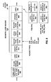
- An example format of a packet 800 for each of these packet types is depicted in Fig. 8 .
- a header is added at each of several different communication protocol layers as the packet 800 is passed downward through the levels before the packet is transmitted to another node 602, 604.
- Fig. 8 An example format of a packet 800 for each of these packet types is depicted in Fig. 8 .
- a header is added at each of several different communication protocol layers as the packet 800 is passed downward through the levels before the packet is transmitted to another node 602, 604.
- the reliability module 306 may assemble a packet of user data 808 with a leading reliability module header 806, which may incorporate data allowing the reliability module 306 to perform the sequencing, positive and/or negative acknowledgment, and other data protection mechanisms described earlier.
- the sockets module 304 attaches a separate sockets layer header 804, providing data capable of supporting the various functions attributed above to the sockets module 304.
- this header 804 is applied to the end of the user data 808 in the data packet 800, although other locations for the sockets layer header 804 may be utilized in other implementations. This data is described in greater detail below.
- the packet 800 is then forwarded to the transport/network layer 310, which attaches a connectionless protocol layer header 802, such as a UDP header, to the packet 800 before transmitting the packet 800 over the network to another node.
- a connectionless protocol layer header 802 such as a UDP header
- other headers and data not illustrated in Fig. 8 may also be added to the packet 800.
- the sockets layer header 804 provided by the sockets module 304 includes a length 810 (in bytes) of the header, a header type 812, a local port indicator 814, a remote port indicator 816, a bitmask 818, and an optional field 820.
- the header type 812 indicates which type of packet (i.e., SYN 610, SYN_ACK 612, ACK 614, DATA 620, FIN 630, or FIN_ACK 632) is represented by the data packet 800.
- the reliability module header 806 and the user data 808 of Fig. 8 are present only if the header type 812 indicates a DATA packet 620.
- the header type 812 may indicate which type of packet by way of bitwise representation, by bit-encoded representation, or by some other means of representation.
- the local port indicator 814 and the remote port indicator 816 denote a particular port for the node originating the packet 800 and a specific port for the node receiving the packet 800, respectively.
- the connectionless protocol header 802 such as a UDP header, may also include port indicators, such as a source port indicator and a destination port indicator. In UDP, such port indicators are typically 16 bits in length, with each port identifying a software structure configured to exchange data specifically associated with a particular application or service.
- the port indicators 814, 816 of the sockets layer header 804 may or may not correspond to the port indicators of the connectionless protocol header 802.
- the local port indicator 814 and the source port of the connectionless protocol header 802 may be the same, as well as the remote port indicator 816 and the destination port of the connectionless protocol header 802 if the two connected nodes 602, 604 reside on the same LAN.
- the connection between the two nodes may be designated by way of an IP address and a port indicator (as designated in both the connectionless protocol header 802 and the sockets layer header 804).
- the two communicating nodes 602, 604 may reside in separate LANs, thus communicating over a WAN.
- a finder ID may be employed to identify at least one or both of the nodes 602, 604.
- the port indicator associated with that node 602, 604 may be a logical port indicator not associated with a port of the connectionless protocol header 802.
- the logical port indicator may be generated at random, thus reducing the likelihood that the logical port indicator will be identical to another logical port indicator associated with another connection between the nodes 602, 604.
- each separate port of a node 602, 604, as identified in the sockets layer header 804, may be associated with a separate connection with another node 602, 604. Accordingly, each connection may be established, used, and terminated in parallel with other connections involving the same node 602, 604, thus allowing the node 602, 604 to service or process several different data streams simultaneously.
- the bitmask 818 may be employed as a mask to condition data provided in the optional field 820.
- the optional field may include a session identifier for each of the nodes 602, 604 associated with a connection.
- each of the packet types i.e., SYN 610, SYN_ACK 612, ACK 614, DATA 620, FIN 630, and FIN_ACK 632
- each of the packet types may include in the sockets layer header 804 a local session identifier 822 for the node 602, 604 issuing the data packet 800, and a remote session identifier 824 associated with the node 602, 604 receiving the packet 800.
- the remote session identifier 824 is set to zero, as the remote session identifier 824 associated with the node 602, 604 receiving the SYN packet 610 is yet to be determined.
- These session identifiers 822, 824 which may be generated randomly for each session, may distinguish different sessions existing at different times over the same port of a node 602, 604. For example, a first stream of audio/video data may be carried over a connection from the second node 604 to the first node 602 via a particular port of the first node 602. At the conclusion of that stream, that connection may be terminated. Another connection involving the same port of the first node 602 may then be established to carry another audio/video stream, thus representing a different session.
- the first node 602 may safely ignore or discard late-arriving packets 800 of the previous session based on the older session identifier 822, 824 included in the sockets layer header 804 of the older packets 800.
- Embodiments described herein for establishing connections between two network nodes by way of a connectionless communication protocol provide a number of advantages. Overall, establishing connections in such a manner allows the use of a standard connectionless transport layer, such as UDP, with its minimal communication overhead, as well as its associated network IP layer, while incorporating connection mechanisms which potentially surpass the connection performance normally associated with TCP, such as by providing handshaking retry mechanisms, robust support for multiple concurrent connections, and other advantages. Software or firmware implementing the various embodiments described may facilitate deployment of advanced data reliability schemes that may perform better than TCP in certain challenging communication environments.
Landscapes
- Engineering & Computer Science (AREA)
- Computer Networks & Wireless Communication (AREA)
- Signal Processing (AREA)
- Computer Security & Cryptography (AREA)
- Communication Control (AREA)
- Data Exchanges In Wide-Area Networks (AREA)
Abstract
Description
- The present invention relates to a method and node for establishing a network connection by way of a connectionless transport layer protocol.
- The Internet has become an important communication network for transporting data of many kinds, including textual, audio, and visual data, between distinct nodes of the network. The transfer of this data within the Internet is facilitated by a "stack" of architectural "layers", with each layer providing a corresponding type of functionality required of the network to transport the data. Each of these layers at least roughly corresponds to one or more of the seven layers of the Open Systems Interconnection (OSI) Reference Model, which identifies seven different layers, namely the physical layer, the data link layer, the network layer, the transport layer, the session layer, the presentation layer, and the application layer, in ascending order. Only one of these layers represents the actual physical network connection. The remaining layers describe the various types of data and associated control information being generated and transferred within the network.
- While different portions of the Internet often utilize diverse physical and data link layers, much of the Internet employs some version of the Internet Protocol (IP) for the network layer. Above the IP layer, however, several different options exist for the transport layer. Two of the more popular options are the Transmission Control Protocol (TCP) and the User Datagram Protocol (UDP). Generally, TCP provides for logical connections to be established between two end nodes of the network for subsequent data transfer therebetween. TCP provides a data packet acknowledgement, timeout, and retransmission mechanism, as well as a packet sequencing facility, to protect against data loss. Conversely, UDP does not provide an acknowledgement, timeout, or retransmission mechanism, does not explicitly facilitate data packet sequencing, and does not establish a logical connection between two communicating network nodes. Due to its lower overhead, UDP is often utilized in situations in which data loss is less important than any additional delay that may be incurred by using TCP for data packet transmission. By contrast, TCP is typically employed in scenarios in which data reliability and integrity are important considerations.
- Many network-connected computer systems provide a software "sockets" application programming interface (API) to allow software applications executing on the system to employ UDP, TCP, and other types of transport layers to communicate with other nodes on the network. One such API is the Berkeley Software Distribution (BSD) Sockets API, which provides a number of functions that may be called by applications to create and terminate connections over a network with another node, exchange data over such connections, and perform related activities using TCP, UDP, or another transport layer implementation.
- While the use of TCP, UDP, the BSD sockets API, and other typical implementations of the various architectural layers of the Internet is widely accepted, use of these standard communication tools by two communication network nodes may not adequately address some specific data characteristics, network environments, and other concerns.
-
US-A-2008/0075048 describes a socket module on a wireless communication device which establishes and maintains open UDP sockets with a remote server over a wireless communication network and manages the dormancy state of the radio link to the wireless communication network. The state of the radio link may be either active or dormant and the socket module keeps the UDP socket open even when the state of the radio link is dormant, thereby reducing setup time for communications between the wireless device and the remote server. The socket module is configured to maintain multiple open sockets for a plurality of applications that may run on the wireless device and thereby operate as a passive server for such applications on the wireless device. -
US-A-2003/0115357 describes a socket migration architecture for migrating a communication socket among host devices and having a plurality of migrateable sockets each operating in conjunction with one of a plurality of applications on a plurality of host devices. Each of the applications may utilize a respective migrateable socket to establish peer-to-peer communications with at least one other application. Upon establishment of such communications, the migrateable sockets may form an association link between migrateable sockets operating on different host devices. When a first application and respective first migrateable socket are migrated from a first host device to a second host device, at least one association link established prior to the migration may be used to reestablished peer-to-peer communications as part of the migration event. -
US-A-2008/0281976 describes an apparatus including a plurality ofUDP ports capable of receiving UDP messages and a message generator to generate a request message to be transmitted to remote endpoints connected over a network via a connectionless diagram protocol. The request message includes a header section having data identifying a plurality of reply-to addresses corresponding to the UDP ports. The requesting device and the responding devices will have an understanding that each responding device can send their response messages to "any" of reply-to addresses listed in the request message transmitted by the requesting device. Each responding device which receives a request message randomly chooses which of the reply-to-addresses to respond to. - The present invention seeks to provide a method to establish a network connection which, whilst having reliability and integrity, keeps its overhead low.
- The invention is defined in the independent claims. Further embodiments are defined in the dependent claims.
- According to a first aspect of the present invention there is provided a method of establishing a network connection between first and second nodes by way of a connectionless transport layer communication protocol, the method utilising data packets which each comprise a header and a payload formatted according to the connectionless protocol, the connectionless protocol payload of each data packet comprising a separate header having a first port indicator for the first node and a second port indicator for the second node; and the method comprising exchanging data packets between the first and second nodes, identifying at each node that a connection between the first and second nodes is to be established by the presence of the first and second port indicators in the data packets exchanged between the first and second nodes, and establishing a connection between the first and second nodes in response to the exchange and identifying steps.
- Preferably, the separate header of at least one of the data packets includes an indication that a connection between the first and second nodes is to be established, and a connection between the two nodes is established upon receipt at one of the nodes of said indication.
- In an embodiment, the separate header of at least one of the data packets includes a first session identifier for the first node and a second session identifier for the second node, and the method further comprises utilising at least one of the first session identifier and the second session identifier to verify whether the data packets belong to a current session.
- For example, the method may further comprise discarding data packets identified as not belonging to the current session.
- In an embodiment, exchanging data packets comprises transmitting a first data packet from the first node to the second node, receiving the first data packet at the second node; and transmitting a second data packet from the second node to the first node.
- Preferably, the method further comprises awaiting the second data packet at the first node; and retransmitting the first data packet from the first node to the second node if the second data packet is not received at the first node within a first predetermined time period after the transmitting of the first data packet.
- The separate header of the first data pocket may include an indication to establish a connection with the second node, and the separate header of the second data packet may include an indication of an acknowledgment of the indication to establish a connection of the first data packet.
- Preferably the connectionless protocol comprises a user datagram protocol.
- The present invention also extends to node for a communication network comprising a communication interface arranged to exchange data packets with another node of the network by way of a connectionless transport layer communication protocol; and control circuitry for generating data packets which each comprise a header and a payload formatted according to the connectionless protocol, the connectionless protocol payload of each data packet comprising a separate header having a first port indicator for the first node and a second port indicator for the second node; wherein the control circuitry is arranged to exchange data packets, by way of the communication interface, with the other node; wherein the control circuitry is arranged to identify that a connection of the node is to be established with the other node by identifying the presence of the first and second port indicators; and wherein the control circuitry is arranged to establish the connection between the node and the other node in response to the exchange and identification.
- Preferably, the control circuitry is arranged to generate data packets and to transmit the data packets to the other node, and wherein the control circuitry is arranged to receive data packets from the other node whereby data packets are exchanged.
- In an embodiment, the connectionless protocol comprises a user datagram protocol.
- Embodiments of the present invention will hereinafter be described, by way of example, with reference to the accompanying drawings, in which:
-
Fig. 1 shows a simplified block diagram of two nodes of a communication network; -
Fig. 2 is a flow diagram of a method of an embodiment of the invention for establishing a connection between two nodes; -
Fig. 3 is a block diagram of a communication software hierarchy for a network node; -
Fig. 4 is a listing of example functions forming a sockets application programming interface as shown inFig. 3 ; -
Fig. 5 is a simplified block diagram of a network node configured to establish a connection with another node; -
Fig. 6 is communication diagram of a handshaking protocol for establishing and terminating a connection between client and server nodes; -
Fig. 7 is a state diagram depicting the establishment and termination of a connection between two nodes; and -
Fig. 8 is a graphical representation of a header generated by a sockets application programming interface within data packets transmitted between network nodes. -
Fig. 1 shows a simplified block diagram of acommunication network 100 in which afirst node 102 and asecond node 104 may establish alogical connection 110 therebetween for the transfer of data. Such aconnection 110 is a logical association of the twonodes connection 110 may facilitate error correction and other worthwhile mechanisms for the data being transferred. Thenetwork 100 may be any communication network over which digital data may be carried or transferred, including a local area network (LAN), or a wide area network (WAN), such as the Internet. Whilst the Figure implies a direct coupling between thenodes nodes -
Fig. 2 is a flow diagram of amethod 200 for establishing theconnection 110 between thefirst node 102 and thesecond node 104 via a connectionless transport layer communication protocol. A connectionless transport layer communication protocol facilitates a basic mechanism for the transmission of "datagrams" without explicitly establishing a connection between the source and destination nodes involved beforehand. As a result, protection mechanisms, such as retransmission, error correction, sequencing of datagrams, and the like, are not implemented in the connectionless protocol in order to reduce overhead and increase data throughput. One example of a connectionless transport layer protocol is the User Datagram Protocol (UDP), which is commonly implemented in addition to the Transmission Control Protocol (TCP) atop the Internet Protocol (IP) network layer in a standard TCP/IP stack. - In the
method 200, a plurality ofdata packets 106 are exchanged between thefirst node 102 and thesecond node 104 of the network 100 (operation 202). As suggested inFig. 1 , thedata packets 106 transmitted from thefirst node 102 to thesecond node 104 may be transmitted over a different path through thenetwork 100 to thosepackets 106 traveling in the opposite direction. Each of thedata packets 106 includes a header and a payload formatted according to the connectionless transport layer communication protocol. Generally, a data packet header is control and/or status information related to the payload residing in the data packet, and is currently positioned at the end of thedata packet 106, although other locations within the data packet are possible. Further, the connectionless protocol payload includes a separate header including a first port indicator for thefirst node 102 and a second port indicator for thesecond node 104. A port number may be any indicator or value designating a logical input or pathway of a node identified with a particular set of communications. Also, the separate header of at least one of the data packets includes an indication to establish aconnection 110 between thefirst node 102 and thesecond node 104. - In response to the exchange of the
data packets 106, thefirst node 102 and thesecond node 104 establish theconnection 110 between thefirst node 102 and thesecond node 104, wherein the first port indicator and the second port indicator are associated with the established connection 110 (operation 204). A computer-readable storage medium may have encoded thereon instructions for a processor or other control circuitry to direct a device to implement themethod 200. - Use of the
method 200 may thus allow thenodes network 100, may be employed in lieu of the TCP protocol by employing the connectionless UDP protocol and underlying network layers as a data transmission mechanism. Further, the new transport layer may address communication situations associated with the nature of the data being transferred, the type of communication links being employed, and other characteristics that are not handled efficiently by a more standardized transport layer connection protocol. -
Fig. 3 is a block diagram of a particularcommunication software hierarchy 300 which may be implemented within a network node. Thehierarchy 300, when implemented within each of two network nodes, facilitates the establishment of a connection between the nodes over a connectionless transport layer communication protocol. Whilst the following discussion focuses on thespecific hierarchy 300 ofFig. 3 as a software platform by which the connection may be established, other software architectural configurations may be employed to similar effect in other implementations. - The
software hierarchy 300 includes anapplication 302, a "sockets"module 304, areliability module 306, aconnectivity module 308, and a transport/networklayer protocol stack 310, such as a TCP/IP stack, including support for a connectionless transport layer protocol, such as UDP. Theapplication 302 may be any application-level software requiring access to a communication network. In one specific implementation, theapplication 302 may be an audio/video stream source and/or display application, thus necessitating access to the communication network for the transmission and/or reception of audio/video data. For example, an audio/video destination, such as a computer system, a personal digital assistant (PDA), or a mobile communication device, may attempt to establish a communication connection with a video source node, such as a Slingbox by Sling Media, Inc., coupled to a satellite or cable set-top box, so that the destination node may stream video from the set-top box via the source node over the network. In this case, the source node may be viewed as a server node, while the destination node may be regarded as a client-node, with both the server node and the client node each separately implementing thesoftware hierarchy 300 ofFig. 3 . - The
sockets module 304 provides an application programming interface (API) through which theapplication 302 of the client or server device may access the network, including the establishment of connections and transfer of data over such connections. Such an interface is often facilitated by way of a set of function calls provided by thesockets module 304, such as those shown inFig. 4 , and explained in greater detail below. Generally, a "socket" is an endpoint of a communication path through the network defined by a node address (such as an IP address) and a port number. Thesockets module 304 allows theapplication 302 to create one or more such sockets, request a connection to another node using the socket, transmit and/or receive data via the socket, free the socket, and other applicable tasks. Accordingly, thesockets module 304 implements many of the operations discussed below concerning establishment and termination of one or more connections by way of a packet-based handshaking protocol using a connectionless transport layer protocol, retransmission of lost handshaking packets, and other functionality. - The
sockets module 304 accesses thereliability module 306 to facilitate various protection mechanisms for the user data being transferred over an established connection between network nodes. Such mechanisms may include, but are not limited to, sequencing of the user data packets to facilitate their proper ordering at the receiving node, acknowledgment (or non-acknowledgment) and retransmission of lost user data packets, and other functionality not provided by a connectionless transport layer protocol, such as UDP. Further, thereliability module 306 may implement such protections as a replacement for the standard TCP layer. - As shown in
Fig. 3 , thesockets module 304 may further interface with aconnection module 308, which may facilitate the creation of "tunnels" or other mechanisms for maintaining a viable communication path between two network nodes. - The
sockets module 304 also communicates with the standardized transport/network protocol stack 310, such as a TCP/IP stack which incorporates a connectionless transport layer protocol, such as UDP. Thesockets module 304 employs the UDP portion of the TCP/IP stack, thus circumventing TCP whilst implementing the connection handshake mechanism. Sequencing and retransmission capabilities supplied by thereliability module 306 may also be implemented in lieu of the corresponding functionality normally provided in TCP. Thus, the functionality provided by thesockets module 304, thereliability module 306, and theconnectivity module 308 may be tailored to address various aspects of specific communication environments more efficiently than that provided by TCP. - As shown in
Fig. 3 , theapplication 302 communicates with thesockets module 304 by way of function calls 320 without having to engage in the specific details of theother modules software hierarchy 300. In turn, thesockets module 304 handles the required communications with theother modules general control path 322 between thesockets module 304 and thereliability module 306, as well as between thesockets module 304 and each of theconnectivity module 308 and theprotocol stack 310, allows thesockets module 304 to control each resulting protocol layer involving in network communications with another node. -
Fig. 4 provides a listing of possible function calls 320 presented to theapplication 302, some of which are briefly described below. For example, sInit() and sclose() allocate and release, respectively, the various structures and overall context for the sockets used for network communications. The functions sCreateSocket() and sclosesocket() facilitate the creation and deletion of a specific socket employed in a communication connection. A created socket may then be bound to a particular IP address and port by way of the sBind() function. Creation of a connection using an existing socket is accomplished by way of one or more of the sListen(), sConnent(), and sAccept() functions, based on whether theapplication 302 is acting as a client (and, thus, is initiating a connection) or a server (which receives and acknowledges such an initiation). Once a connection is established, data may be sent to and received from another node by way of thereliability module 306 via the sSend() and sRecv() functions, which allow the application to read from and write to data buffers supplied by thereliability module 306. Other functions may provide access to control and status data, as well as other aspects, of thesockets module 304. - The
sockets module 304 may handle a number of asynchronous events, such as those initiated by communication activity of another node on the network. For example, thesockets module 304 may respond to attempts by the other node to establish a new connection, terminate an existing connection, or to transmit data to the node employing thesockets module 304. Such events may be serviced by way of interrupt control, polling, or other asynchronous event-handling means. -
Fig. 5 provides a simplified block diagram of anode 500 of a communication network. Thenode 500 includes acommunication interface 502 andcontrol circuitry 504. Thecommunication interface 502 is configured to transmit and receive data packets with another node of the network. For example, thecommunication interface 502 is an interface configured to communicate over an IP interface implemented over a wired or wireless link/physical layer. Examples of such layers include Ethernet, Wi-Fi (e.g., IEEE 802.11a/b/g/n), digital subscriber line (DSL), cable modem, and others. Network layers other than IP may be employed in other arrangements. Thecommunication interface 502 may be implemented as a network interface card (NIC), circuitry located on a computer system motherboard, or via other circuit means. - The
control circuitry 504 is configured to generate and transmit data packets via thecommunication interface 502 to one or more other nodes, as well as to receive and process data packets from those nodes by way of theinterface 502. The structure and use of those packets is discussed below. Thecontrol circuitry 504 may include one or more processors, such as a microprocessor, microcontroller, or digital signal processor (DSP), arranged to execute instructions directing the processor to perform the functions and facilitate the communication discussed in greater detail below. Thecontrol circuitry 502 may also include memory or data storage containing the instructions. Thecontrol circuitry 502 may be strictly hardware-based logic, or may include a combination of hardware, firmware, and/or software elements. -
Fig. 6 is a communication diagram 600 exemplifying various data packets transmitted by afirst node 602 and asecond node 604 to establish a connection, transfer data, and then terminate the connection. Similarly,Fig. 7 is a state diagram 700 depicting the various possible states and associated state transitions each of thenodes first node 602 operates as a client node, whilst thesecond node 604 is a server node. As in most client-server arrangements, thesecond node 604 is arranged to receive connection requests prior to the transmission of such a request by thefirst node 602. One example of such an arrangement may be a user computer client requesting an audio/video data stream from a Slingbox server, which delivers audio/video sourced by a set-top box over the network to the client computer. Of course, other communication environments involving different forms of data may benefit from the described formats. - In
Fig. 7 , both the first (client)node 602 and the second (server)node 604 are presumed to reside in theCLOSED state 702, indicating that no connection is current established between thenodes nodes respective connectivity module 308 to create a tunnel or other communication path via the transport/network layer 310, thus placing bothnodes TUNNEL_CREATED state 704. In one implementation, the tunnel or path is identified by way of a device address, such as an IP address, for each of thenodes nodes nodes node - After the creation of the tunnel or path, the
first node 602 transmits aSYN data packet 610, thus initiating a handshake with thesecond node 604 to establish a connection. TheSYN data packet 610, as well as all subsequent data packets involving the same connection, identify a local port indicator associated with thefirst node 602 and a remote port indicator associated with thesecond node 604. Thus, the particular connection to be established is identified by way of these port indicators, thus allowing multiple connections to be established between thenodes application 302 of thenode sockets module 304. - As a result of transmitting the
SYN data packet 610 to thesecond node 604, thefirst node 602 assumes theSYN_SENT state 706 and awaits an affirmative response from thesecond node 604. Theapplication 302 initiates the handshake by way of the sConnect() function call described earlier. - In response to receiving the
SYN data packet 610, thesecond node 604 transitions to theSYN_RECEIVED state 708. Thesecond node 604 employs the sListen() function to enable itssockets module 304 prior to transmission of theSYN data packet 610 to receive theSYN data packet 610. Thereafter, thesecond node 604 transfers aSYN_ACK data packet 612 to thefirst node 602 to continue the handshake, and assumes theSYN_ACK_SENT state 710. In one implementation, once theSYN data packet 610 is received, thesockets module 304 notifies theapplication 302, which in turn calls the sAccept() module to transmit theSYN_ACK data packet 612. - To implement error recovery in the case of a missing or defective
SYN data packet 610 orSYN_ACK data packet 612, either of which would cause thefirst node 602 to not receive theSYN_ACK packet 612, thefirst node 602 may implement a timeout period that is initiated after theSYN data packet 610 is transmitted. If thefirst node 602 then does not receive theSYN_ACK data packet 612 during the timeout period, thefirst node 602 may return to theTUNNEL_CREATED state 704, retransmit theSYN data packet 610, and transition again to theSYN_SENT state 706. Thefirst node 602 may retransmit theSYN data packet 610 several times up to some maximum number while a correspondingSYN_ACK data packet 612 is not received. The time period may be different for two or more of the possible retransmissions of theSYN data packet 610, with the time periods possibly increasing or decreasing for each successive retransmission. - Presuming that the
first node 602 successfully received theSYN_ACK data packet 612, thefirst node 602 would then complete the handshake by transmitting anACK data packet 614 to thesecond node 604 to confirm receipt of theSYN_ACK data packet 612, and transition from theSYN_SENT state 706 to the CONNECTION_ESTABLISHED state 714. Correspondingly, upon receiving theACK data packet 614, thesecond node 604 also assumes the CONNECTION_ESTABLISHED state 714, thus placing bothnodes - Similar to the retransmission scheme employed by the
first node 602 for theSYN data packet 610 discussed above, thesecond node 604 may implement error recovery in the case of a missing or defectiveSYN_ACK data packet 612 orACK data packet 614, either of which may prevent thesecond node 604 from properly receiving theACK packet 614. More specifically, thesecond node 604 may implement a timeout period that is initiated after thesecond node 604 transmits theSYN_ACK data packet 612. If thesecond node 604 then does not receive theACK data packet 614 during the timeout period, thesecond node 604 may then return to theSYN_RECEIVED state 708, retransmit theSYN_ACK data packet 612, and again assume theSYN_ACK_SENT state 710. Thesecond node 604 may retransmit the SYN_ACK data packet 612 a number of times up to some maximum value while a correspondingACK data packet 614 is not received. The time period may be different for two or more of the possible retransmissions of theSYN_ACK data packet 612, with the time periods possibly increasing or decreasing for each successive retransmission. The number of transmissions, and the associated time periods, may be different from those used for retransmission of theSYN data packet 610. - Presuming instead that the
second node 604 successfully received theACK data packet 614, both of thenodes nodes nodes user data packets 620, such as data packets containing audio/video data, as mentioned above, may then occur between thenodes first node 602 has already received theSYN_ACK data packet 612 from thesecond node 604, and since the mechanism shown inFig. 6 does not require thesecond node 604 to issue an acknowledgment for theACK data packet 614, a retransmission scheme for theACK data packet 614 is generally not required. However, thefirst node 602 may be configured to transmit anACK data packet 614 in response to receiving aSYN_ACK data packet 612 from thesecond node 604 after thefirst node 602 has already attained the CONNECTION_ESTABLISHED state 714. - While in the CONNECTION_ESTABLISHED state 714, the
sockets module 304 facilitates the sending and receiving of data by way of the sSend() and sRecv() functions, which involve use of thereliability module 306 for sending and receiving the data in data packets under a scheme which may include sequencing, positive and/or negative acknowledge, and other protection mechanisms, as mentioned above. - Once either one of the
nodes node application 302 of thefirst node 602 has made this determination, theapplication 302 may initiate the termination of the connection by first using the sCloseSocket() function call, which in turn causes thefirst node 602 to enter theCLOSING state 716, initiate aFIN data packet 630, and transitions thefirst node 602 to theFIN_SENT state 718. Presuming thesecond node 602 successfully receives theFIN data packet 630, thesecond node 604 assumes theFIN_RECEIVED state 720, sends aFIN_ACK data packet 632 to thefirst node 602, and arrives at theCLOSED state 702, indicating that the connection has been terminated. Once thefirst node 602 receives theFIN_ACK data packet 632, thefirst node 602 also enters theCLOSED state 702, thus confirming that the connection is terminated. - While in the
FIN_SENT state 718 after issuing theFIN data packet 630, if thefirst node 602 does not receive a correspondingFIN_ACK data packet 632 within a predetermined time period, thefirst node 602 may return to theCLOSING state 716, retransmit theFIN data packet 630, and proceed to theFIN_SENT state 718 again to await an associatedFIN_ACK data packet 632. Retransmissions may continue for a predefined number of attempts while awaiting theFIN_ACK data packet 632, with a potentially different time period associated with each retransmission. - Given the foregoing connection establishment, data transfer, and data termination mechanism, at least six different types of data packets may be employed, including the
SYN packet 610, theSYN_ACK packet 612, theACK packet 614, theDATA packet 620, theFIN packet 630, and theFIN_ACK packet 632. An example format of apacket 800 for each of these packet types is depicted inFig. 8 . In this example, a header is added at each of several different communication protocol layers as thepacket 800 is passed downward through the levels before the packet is transmitted to anothernode Fig. 8 , in the case of aDATA packet 620 being generated for transmission to another node, thereliability module 306 may assemble a packet ofuser data 808 with a leadingreliability module header 806, which may incorporate data allowing thereliability module 306 to perform the sequencing, positive and/or negative acknowledgment, and other data protection mechanisms described earlier. - As the
packet 800 is transferred from thereliability module 306 to thesockets module 304, thesockets module 304 attaches a separatesockets layer header 804, providing data capable of supporting the various functions attributed above to thesockets module 304. In the example ofFig. 8 , thisheader 804 is applied to the end of theuser data 808 in thedata packet 800, although other locations for thesockets layer header 804 may be utilized in other implementations. This data is described in greater detail below. Thepacket 800 is then forwarded to the transport/network layer 310, which attaches a connectionlessprotocol layer header 802, such as a UDP header, to thepacket 800 before transmitting thepacket 800 over the network to another node. In some embodiments, other headers and data not illustrated inFig. 8 may also be added to thepacket 800. - In
Fig. 8 , thesockets layer header 804 provided by thesockets module 304 includes a length 810 (in bytes) of the header, aheader type 812, alocal port indicator 814, aremote port indicator 816, abitmask 818, and anoptional field 820. Theheader type 812 indicates which type of packet (i.e.,SYN 610,SYN_ACK 612,ACK 614,DATA 620,FIN 630, or FIN_ACK 632) is represented by thedata packet 800. In one implementation, thereliability module header 806 and theuser data 808 ofFig. 8 are present only if theheader type 812 indicates aDATA packet 620. Theheader type 812 may indicate which type of packet by way of bitwise representation, by bit-encoded representation, or by some other means of representation. - The
local port indicator 814 and theremote port indicator 816 denote a particular port for the node originating thepacket 800 and a specific port for the node receiving thepacket 800, respectively. Theconnectionless protocol header 802, such as a UDP header, may also include port indicators, such as a source port indicator and a destination port indicator. In UDP, such port indicators are typically 16 bits in length, with each port identifying a software structure configured to exchange data specifically associated with a particular application or service. Depending on the implementation, theport indicators sockets layer header 804 may or may not correspond to the port indicators of theconnectionless protocol header 802. For example, thelocal port indicator 814 and the source port of theconnectionless protocol header 802 may be the same, as well as theremote port indicator 816 and the destination port of theconnectionless protocol header 802 if the twoconnected nodes connectionless protocol header 802 and the sockets layer header 804). - In another example, the two communicating
nodes nodes node connectionless protocol header 802. In one example, the logical port indicator may be generated at random, thus reducing the likelihood that the logical port indicator will be identical to another logical port indicator associated with another connection between thenodes - Use of the
local port indicator 814 and theremote port indicator 816, whether they refer to logical ports or to ports of theconnectionless protocol header 802, facilitates concurrent multiplexing of different data streams being transmitted or received by asingle node node sockets layer header 804, may be associated with a separate connection with anothernode same node node - The
bitmask 818 may be employed as a mask to condition data provided in theoptional field 820. In one embodiment, the optional field may include a session identifier for each of thenodes Fig. 8 , each of the packet types (i.e.,SYN 610,SYN_ACK 612,ACK 614,DATA 620,FIN 630, and FIN_ACK 632) may include in the sockets layer header 804 alocal session identifier 822 for thenode data packet 800, and aremote session identifier 824 associated with thenode packet 800. In the case of theSYN packet 610, theremote session identifier 824 is set to zero, as theremote session identifier 824 associated with thenode SYN packet 610 is yet to be determined. Thesesession identifiers node second node 604 to thefirst node 602 via a particular port of thefirst node 602. At the conclusion of that stream, that connection may be terminated. Another connection involving the same port of thefirst node 602 may then be established to carry another audio/video stream, thus representing a different session. By employingdifferent session identifiers first node 602 may safely ignore or discard late-arrivingpackets 800 of the previous session based on theolder session identifier sockets layer header 804 of theolder packets 800. - Embodiments described herein for establishing connections between two network nodes by way of a connectionless communication protocol provide a number of advantages. Overall, establishing connections in such a manner allows the use of a standard connectionless transport layer, such as UDP, with its minimal communication overhead, as well as its associated network IP layer, while incorporating connection mechanisms which potentially surpass the connection performance normally associated with TCP, such as by providing handshaking retry mechanisms, robust support for multiple concurrent connections, and other advantages. Software or firmware implementing the various embodiments described may facilitate deployment of advanced data reliability schemes that may perform better than TCP in certain challenging communication environments.
- It will be appreciated that modifications to, and variations in, the embodiments as described and illustrated may be made within the scope of the accompanying claims. For example, whilst various embodiments have been described primarily within the context of network connections carrying audio/video stream communications, the embodiments may transmit and receive any other form of data.
Claims (11)
- A method of establishing a network connection between first and second nodes (102, 104; 602, 604) by way of a connectionless transport layer communication protocol, the method utilising:data packets (106) which each comprise a header and a connectionless protocol payload formatted according to the connectionless transport layer communication protocol,the connectionless protocol payload of each data packet comprising a separate header having a first port indicator for the first node (102; 602) and a second port indicator for the second node (104; 604); andthe method comprising:exchanging (202) data packets between the first and second nodes (102, 104; 602, 604),identifying at each node that a network connection (110) between the first and second nodes is to be established by the presence of the first and second port indicators in the data packets exchanged between the first and second nodes, andestablishing (204) the network connection between the first and second nodes in response to the exchanging and identifying steps.
- A method as claimed in Claim 1, wherein the separate header of at least one of the data packets (106) includes an indication that a connection between the first and second nodes is to be established, and wherein a connection (110) between the two nodes is established upon receipt at one of the nodes of said indication.
- A method as claimed in Claim 1 or Claim 2, wherein the separate header of at least one of the data packets (106) includes a first session identifier (822) for the first node (602) and a second session identifier (824) for the second node (604), and
wherein the method further comprises utilising at least one of the first session identifier and the second session identifier to verify whether the data packets (106) belong to a current session. - A method as claimed in Claim 3, further comprising:discarding data packets (800) identified as not belonging to the current session.
- A method as claimed in any preceding claim, wherein exchanging data packets comprises:transmitting a first data packet (610) from the first node (602) to the second node (604), receiving the first data packet at the second node (604); andtransmitting a second data packet (612) from the second node (604) to the first node (602).
- A method as claimed in Claim 5, further comprising:awaiting the second data packet (612) at the first node (602); andretransmitting the first data packet (610) from the first node to the second node if the second data packet is not received at the first node within a first predetermined time period after the transmitting of the first data packet.
- A method as claimed in Claim 5 or Claim 6, wherein the separate header of the first data packet (610) includes an indication to establish a connection with the second node, and the separate header of the second data packet (612) includes an indication of an acknowledgment of the indication to establish a connection of the first data packet.
- A method as claimed in any preceding claim, wherein the connectionless protocol comprises a user datagram protocol.
- A first node (500) for a communication network comprising:a communication interface (502) arranged to exchange data packets with a second node of the communication network by way of a connectionless transport layer communication protocol; and control circuitry (504) for generating data packets which each comprise a header and a connectionless protocol payload formatted according to the connectionless transport layer communication protocol,the connectionless protocol payload of each data packet comprising a separate header having a first port indicator for the first node and a second port indicator for the second node;wherein the control circuitry (504) is arranged to exchange data packets, by way of the communication interface (502), with the second node;wherein the control circuitry is arranged to identify that a connection between the first and second nodes is to be established by identifying the presence of the first and second port indicators in the exchanged data packets; andwherein the control circuitry (504) is arranged to establish the connection between the first node and the second node in response to the exchange and identification.
- A first node as claimed in Claim 9, wherein the control circuitry (504) is arranged to generate data packets and to transmit the data packets to the second node, and wherein the control circuitry is arranged to receive data packets from the second node whereby data packets are exchanged.
- A first node as claimed in Claim 9 or Claim 10, wherein the connectionless protocol comprises a user datagram protocol.
Applications Claiming Priority (1)
| Application Number | Priority Date | Filing Date | Title |
|---|---|---|---|
| US12/405,062 US8750112B2 (en) | 2009-03-16 | 2009-03-16 | Method and node for employing network connections over a connectionless transport layer protocol |
Publications (2)
| Publication Number | Publication Date |
|---|---|
| EP2230813A1 EP2230813A1 (en) | 2010-09-22 |
| EP2230813B1 true EP2230813B1 (en) | 2012-01-18 |
Family
ID=42470762
Family Applications (1)
| Application Number | Title | Priority Date | Filing Date |
|---|---|---|---|
| EP10156613A Active EP2230813B1 (en) | 2009-03-16 | 2010-03-16 | A method and node for establishing a network connection by way of a connectionless transport layer protocol |
Country Status (3)
| Country | Link |
|---|---|
| US (2) | US8750112B2 (en) |
| EP (1) | EP2230813B1 (en) |
| AT (1) | ATE542349T1 (en) |
Families Citing this family (25)
| Publication number | Priority date | Publication date | Assignee | Title |
|---|---|---|---|---|
| US8266657B2 (en) | 2001-03-15 | 2012-09-11 | Sling Media Inc. | Method for effectively implementing a multi-room television system |
| WO2005122025A2 (en) | 2004-06-07 | 2005-12-22 | Sling Media, Inc. | Personal media broadcasting system |
| US7917932B2 (en) | 2005-06-07 | 2011-03-29 | Sling Media, Inc. | Personal video recorder functionality for placeshifting systems |
| US7975062B2 (en) | 2004-06-07 | 2011-07-05 | Sling Media, Inc. | Capturing and sharing media content |
| US8381310B2 (en) | 2009-08-13 | 2013-02-19 | Sling Media Pvt. Ltd. | Systems, methods, and program applications for selectively restricting the placeshifting of copy protected digital media content |
| US8750112B2 (en) | 2009-03-16 | 2014-06-10 | Echostar Technologies L.L.C. | Method and node for employing network connections over a connectionless transport layer protocol |
| US8171148B2 (en) | 2009-04-17 | 2012-05-01 | Sling Media, Inc. | Systems and methods for establishing connections between devices communicating over a network |
| US8406431B2 (en) | 2009-07-23 | 2013-03-26 | Sling Media Pvt. Ltd. | Adaptive gain control for digital audio samples in a media stream |
| US8984142B2 (en) * | 2009-12-30 | 2015-03-17 | Mckesson Financial Holdings | Methods, apparatuses and computer program products for facilitating remote session pooling |
| WO2013128798A1 (en) * | 2012-03-02 | 2013-09-06 | 日本電気株式会社 | Path control system, control device, and path control method |
| EP2768200B8 (en) * | 2013-02-18 | 2019-09-18 | Forcepoint Finland Oy | Receiving data packets |
| CN103310669B (en) * | 2013-06-09 | 2016-06-22 | 深圳市金华联电子有限公司 | A kind of data transmission method for interactive teaching and system |
| CN104734993B (en) * | 2013-12-24 | 2018-05-18 | 杭州华为数字技术有限公司 | Data distribution method and current divider |
| WO2015117228A1 (en) * | 2014-02-06 | 2015-08-13 | Brett Shellhammer | System, methods, and devices for addressed data communications |
| US9680918B2 (en) * | 2014-06-30 | 2017-06-13 | Fortinet, Inc. | Socket application program interface (API) for efficient data transactions |
| JP6290055B2 (en) * | 2014-09-19 | 2018-03-07 | 株式会社東芝 | COMMUNICATION DEVICE, COMMUNICATION CONTROL METHOD, AND COMPUTER PROGRAM |
| US10419170B2 (en) * | 2015-02-26 | 2019-09-17 | Qualcomm Incorporated | RRC aware TCP retransmissions |
| JP6598188B2 (en) * | 2015-02-27 | 2019-10-30 | 株式会社エヴリカ | Information processing apparatus, method, and program |
| US11115504B2 (en) * | 2018-06-26 | 2021-09-07 | Microsoft Technology Licensing, Llc | Batch processing for QUIC |
| US10931448B2 (en) | 2018-06-28 | 2021-02-23 | DISH Technologies L.L.C. | Authentication through secure sharing of digital secrets previously established between devices |
| US11621980B2 (en) * | 2020-07-07 | 2023-04-04 | Agora Lab, Inc. | System and method for providing upstream directives based on upstream signal quality of wireless network in real-time communication |
| US11470531B2 (en) | 2020-07-13 | 2022-10-11 | Agora Lab, Inc. | System and method for automatically switching real-time communication device to new basic service set |
| US11350314B2 (en) * | 2020-07-13 | 2022-05-31 | Agora Lab, Inc. | System and method for classifying network data packets with provided classifier identifiers |
| US11611542B2 (en) | 2021-08-11 | 2023-03-21 | Dish Network Technologies India Private Limited | Secure media streaming communication via user datagram protocol |
| WO2026115536A1 (en) * | 2024-11-28 | 2026-06-04 | Cyata Security Ltd | Secure privileged access management |
Family Cites Families (35)
| Publication number | Priority date | Publication date | Assignee | Title |
|---|---|---|---|---|
| US6273622B1 (en) * | 1997-04-15 | 2001-08-14 | Flash Networks, Ltd. | Data communication protocol for maximizing the performance of IP communication links |
| US6535878B1 (en) * | 1997-05-02 | 2003-03-18 | Roxio, Inc. | Method and system for providing on-line interactivity over a server-client network |
| US6957346B1 (en) * | 1999-06-15 | 2005-10-18 | Ssh Communications Security Ltd. | Method and arrangement for providing security through network address translations using tunneling and compensations |
| US7353380B2 (en) * | 2001-02-12 | 2008-04-01 | Aventail, Llc, A Subsidiary Of Sonicwall, Inc. | Method and apparatus for providing secure streaming data transmission facilities using unreliable protocols |
| US6816455B2 (en) * | 2001-05-09 | 2004-11-09 | Telecom Italia S.P.A. | Dynamic packet filter utilizing session tracking |
| JP2005503722A (en) * | 2001-09-21 | 2005-02-03 | ブリティッシュ・テレコミュニケーションズ・パブリック・リミテッド・カンパニー | Data communication method and system using reception of buffer size to calculate transmission rate for congestion control |
| US6920501B2 (en) * | 2001-12-17 | 2005-07-19 | Ntt Docomo, Inc. | Communication socket migration among different devices |
| US7535913B2 (en) * | 2002-03-06 | 2009-05-19 | Nvidia Corporation | Gigabit ethernet adapter supporting the iSCSI and IPSEC protocols |
| US7370194B2 (en) * | 2002-06-10 | 2008-05-06 | Microsoft Corporation | Security gateway for online console-based gaming |
| US7650416B2 (en) * | 2003-08-12 | 2010-01-19 | Riverbed Technology | Content delivery for client-server protocols with user affinities using connection end-point proxies |
| US7231404B2 (en) * | 2003-01-31 | 2007-06-12 | Nokia Corporation | Datacast file transmission with meta-data retention |
| FI118619B (en) * | 2003-05-16 | 2008-01-15 | Jarmo Talvitie | Method and system for encrypting and storing information |
| US7581010B2 (en) * | 2003-07-14 | 2009-08-25 | Microsoft Corporation | Virtual connectivity with local connection translation |
| US7769866B2 (en) * | 2003-07-14 | 2010-08-03 | Microsoft Corporation | Virtual connectivity with subscribe-notify service |
| KR20060093704A (en) * | 2003-09-30 | 2006-08-25 | 코닌클리케 필립스 일렉트로닉스 엔.브이. | Client Request External Address Mapping |
| GB0402739D0 (en) * | 2004-02-09 | 2004-03-10 | Saviso Group Ltd | Methods and apparatus for routing in a network |
| US7773550B2 (en) * | 2004-04-05 | 2010-08-10 | Daniel J. LIN | Peer-to-peer mobile data transfer method and device |
| US20050265252A1 (en) * | 2004-05-27 | 2005-12-01 | International Business Machines Corporation | Enhancing ephemeral port allocation |
| US20060050717A1 (en) * | 2004-09-09 | 2006-03-09 | International Business Machines Corporation | Reducing delays associated with port binding |
| US7392323B2 (en) * | 2004-11-16 | 2008-06-24 | Seiko Epson Corporation | Method and apparatus for tunneling data using a single simulated stateful TCP connection |
| US7558862B1 (en) * | 2004-12-09 | 2009-07-07 | LogMeln, Inc. | Method and apparatus for remotely controlling a computer with peer-to-peer command and data transfer |
| US7738468B2 (en) * | 2005-03-22 | 2010-06-15 | Logitech Europe S.A. | Method and apparatus for packet traversal of a network address translation device |
| US20060230163A1 (en) * | 2005-03-23 | 2006-10-12 | Fish Russell H Iii | System and method for securely establishing a direct connection between two firewalled computers |
| US20070070996A1 (en) * | 2005-09-26 | 2007-03-29 | Oran David R | Port hopping scheme for peer-to-peer connections |
| US7984180B2 (en) * | 2005-10-20 | 2011-07-19 | Solarflare Communications, Inc. | Hashing algorithm for network receive filtering |
| US9167000B2 (en) * | 2006-02-14 | 2015-10-20 | Ca, Inc. | Dynamic threat event management system and method |
| US7760628B2 (en) * | 2006-09-26 | 2010-07-20 | Kyocera Corporation | Socket based passive server |
| US20080285565A1 (en) * | 2006-11-15 | 2008-11-20 | Utah State University | Systems and methods for content insertion within a router |
| US8145775B2 (en) * | 2007-05-08 | 2012-03-27 | Canon Kabushiki Kaisha | Method to receive UDP response messages across multiple incoming UDP ports |
| US7818433B2 (en) * | 2007-08-16 | 2010-10-19 | International Business Machines Corporation | System and method for minimizing retry delays in high traffic computer networks |
| US8103785B2 (en) * | 2007-12-03 | 2012-01-24 | Seafire Micros, Inc. | Network acceleration techniques |
| US20100011375A1 (en) * | 2008-07-14 | 2010-01-14 | Safenet, Inc. | Zero-install IP security |
| US8228861B1 (en) * | 2008-09-12 | 2012-07-24 | Nix John A | Efficient handover of media communications in heterogeneous IP networks using handover procedure rules and media handover relays |
| US8750112B2 (en) | 2009-03-16 | 2014-06-10 | Echostar Technologies L.L.C. | Method and node for employing network connections over a connectionless transport layer protocol |
| US8843738B2 (en) * | 2012-05-14 | 2014-09-23 | Sierra Wireless, Inc. | TLS abbreviated session identifier protocol |
-
2009
- 2009-03-16 US US12/405,062 patent/US8750112B2/en active Active
-
2010
- 2010-03-16 AT AT10156613T patent/ATE542349T1/en active
- 2010-03-16 EP EP10156613A patent/EP2230813B1/en active Active
-
2014
- 2014-06-09 US US14/299,536 patent/US9049144B2/en active Active
Also Published As
| Publication number | Publication date |
|---|---|
| US20140301389A1 (en) | 2014-10-09 |
| EP2230813A1 (en) | 2010-09-22 |
| US20100232438A1 (en) | 2010-09-16 |
| US9049144B2 (en) | 2015-06-02 |
| US8750112B2 (en) | 2014-06-10 |
| ATE542349T1 (en) | 2012-02-15 |
Similar Documents
| Publication | Publication Date | Title |
|---|---|---|
| US8750112B2 (en) | Method and node for employing network connections over a connectionless transport layer protocol | |
| US8169914B2 (en) | Method and node for transmitting data over a communication network using negative acknowledgment | |
| US9577791B2 (en) | Notification by network element of packet drops | |
| TW419919B (en) | TCP resegmentation | |
| CN101663590B (en) | Parsing out of order data packets at a content gateway of a network | |
| US6694471B1 (en) | System and method for periodic retransmission of messages | |
| JP3448481B2 (en) | TCP communication speed-up device for asymmetric line | |
| US7742454B2 (en) | Network performance by dynamically setting a reassembly timer based on network interface | |
| US20080225847A1 (en) | Article for improved network performance by avoiding ip-id wrap-arounds causing data corruption on fast networks | |
| US20060002301A1 (en) | Transferring transmission control protocol packets | |
| WO2014092779A1 (en) | Notification by network element of packet drops | |
| US12206588B2 (en) | System and method for reducing bandwidth usage of a network | |
| CN106788911A (en) | A kind of method and apparatus of message retransmission | |
| US7480301B2 (en) | Method, system and article for improved TCP performance during retransmission in response to selective acknowledgement | |
| CN108173851B (en) | An efficient multimedia transmission method for spatial information network | |
| US7349384B2 (en) | Reliable one-way messaging over request-response transport protocols | |
| EP1515511A2 (en) | Multiple offload of network state objects with support for failover events | |
| US20050038899A1 (en) | Method, system and article for client application control of network transmission loss tolerance | |
| CN105227276B (en) | A kind of peer-to-peer network data transmission method based on UDT | |
| JP2005136684A (en) | Data transfer method, TCP proxy device, and network system using the same | |
| CN119892953A (en) | Interactive establishment and transmission method of network transmission layer protocol | |
| CN100512288C (en) | Message transmission system based on transmission control protocol and method thereof | |
| EP3367599B1 (en) | Method and system for transferring data within a layered architecture of network components | |
| JP2007093693A (en) | Encrypted communication method and communication apparatus | |
| Padhye | Internet Engineering Task Force INTERNET-DRAFT Eddie Kohler draft-ietf-dccp-spec-01. txt Mark Handley Sally Floyd ICIR |
Legal Events
| Date | Code | Title | Description |
|---|---|---|---|
| PUAI | Public reference made under article 153(3) epc to a published international application that has entered the european phase |
Free format text: ORIGINAL CODE: 0009012 |
|
| AK | Designated contracting states |
Kind code of ref document: A1 Designated state(s): AT BE BG CH CY CZ DE DK EE ES FI FR GB GR HR HU IE IS IT LI LT LU LV MC MK MT NL NO PL PT RO SE SI SK SM TR |
|
| AX | Request for extension of the european patent |
Extension state: AL BA ME RS |
|
| 17P | Request for examination filed |
Effective date: 20110322 |
|
| RIC1 | Information provided on ipc code assigned before grant |
Ipc: H04L 29/06 20060101AFI20110518BHEP |
|
| GRAP | Despatch of communication of intention to grant a patent |
Free format text: ORIGINAL CODE: EPIDOSNIGR1 |
|
| GRAS | Grant fee paid |
Free format text: ORIGINAL CODE: EPIDOSNIGR3 |
|
| GRAA | (expected) grant |
Free format text: ORIGINAL CODE: 0009210 |
|
| AK | Designated contracting states |
Kind code of ref document: B1 Designated state(s): AT BE BG CH CY CZ DE DK EE ES FI FR GB GR HR HU IE IS IT LI LT LU LV MC MK MT NL NO PL PT RO SE SI SK SM TR |
|
| REG | Reference to a national code |
Ref country code: GB Ref legal event code: FG4D |
|
| REG | Reference to a national code |
Ref country code: CH Ref legal event code: EP |
|
| REG | Reference to a national code |
Ref country code: IE Ref legal event code: FG4D Ref country code: AT Ref legal event code: REF Ref document number: 542349 Country of ref document: AT Kind code of ref document: T Effective date: 20120215 |
|
| REG | Reference to a national code |
Ref country code: DE Ref legal event code: R096 Ref document number: 602010000671 Country of ref document: DE Effective date: 20120322 |
|
| REG | Reference to a national code |
Ref country code: NL Ref legal event code: T3 |
|
| LTIE | Lt: invalidation of european patent or patent extension |
Effective date: 20120118 |
|
| PG25 | Lapsed in a contracting state [announced via postgrant information from national office to epo] |
Ref country code: LT Free format text: LAPSE BECAUSE OF FAILURE TO SUBMIT A TRANSLATION OF THE DESCRIPTION OR TO PAY THE FEE WITHIN THE PRESCRIBED TIME-LIMIT Effective date: 20120118 Ref country code: IS Free format text: LAPSE BECAUSE OF FAILURE TO SUBMIT A TRANSLATION OF THE DESCRIPTION OR TO PAY THE FEE WITHIN THE PRESCRIBED TIME-LIMIT Effective date: 20120518 Ref country code: BG Free format text: LAPSE BECAUSE OF FAILURE TO SUBMIT A TRANSLATION OF THE DESCRIPTION OR TO PAY THE FEE WITHIN THE PRESCRIBED TIME-LIMIT Effective date: 20120418 Ref country code: BE Free format text: LAPSE BECAUSE OF FAILURE TO SUBMIT A TRANSLATION OF THE DESCRIPTION OR TO PAY THE FEE WITHIN THE PRESCRIBED TIME-LIMIT Effective date: 20120118 Ref country code: HR Free format text: LAPSE BECAUSE OF FAILURE TO SUBMIT A TRANSLATION OF THE DESCRIPTION OR TO PAY THE FEE WITHIN THE PRESCRIBED TIME-LIMIT Effective date: 20120118 Ref country code: NO Free format text: LAPSE BECAUSE OF FAILURE TO SUBMIT A TRANSLATION OF THE DESCRIPTION OR TO PAY THE FEE WITHIN THE PRESCRIBED TIME-LIMIT Effective date: 20120418 |
|
| PG25 | Lapsed in a contracting state [announced via postgrant information from national office to epo] |
Ref country code: PL Free format text: LAPSE BECAUSE OF FAILURE TO SUBMIT A TRANSLATION OF THE DESCRIPTION OR TO PAY THE FEE WITHIN THE PRESCRIBED TIME-LIMIT Effective date: 20120118 Ref country code: FI Free format text: LAPSE BECAUSE OF FAILURE TO SUBMIT A TRANSLATION OF THE DESCRIPTION OR TO PAY THE FEE WITHIN THE PRESCRIBED TIME-LIMIT Effective date: 20120118 Ref country code: PT Free format text: LAPSE BECAUSE OF FAILURE TO SUBMIT A TRANSLATION OF THE DESCRIPTION OR TO PAY THE FEE WITHIN THE PRESCRIBED TIME-LIMIT Effective date: 20120518 Ref country code: LV Free format text: LAPSE BECAUSE OF FAILURE TO SUBMIT A TRANSLATION OF THE DESCRIPTION OR TO PAY THE FEE WITHIN THE PRESCRIBED TIME-LIMIT Effective date: 20120118 Ref country code: GR Free format text: LAPSE BECAUSE OF FAILURE TO SUBMIT A TRANSLATION OF THE DESCRIPTION OR TO PAY THE FEE WITHIN THE PRESCRIBED TIME-LIMIT Effective date: 20120419 |
|
| REG | Reference to a national code |
Ref country code: AT Ref legal event code: MK05 Ref document number: 542349 Country of ref document: AT Kind code of ref document: T Effective date: 20120118 |
|
| PG25 | Lapsed in a contracting state [announced via postgrant information from national office to epo] |
Ref country code: CY Free format text: LAPSE BECAUSE OF FAILURE TO SUBMIT A TRANSLATION OF THE DESCRIPTION OR TO PAY THE FEE WITHIN THE PRESCRIBED TIME-LIMIT Effective date: 20120118 |
|
| PG25 | Lapsed in a contracting state [announced via postgrant information from national office to epo] |
Ref country code: EE Free format text: LAPSE BECAUSE OF FAILURE TO SUBMIT A TRANSLATION OF THE DESCRIPTION OR TO PAY THE FEE WITHIN THE PRESCRIBED TIME-LIMIT Effective date: 20120118 Ref country code: SE Free format text: LAPSE BECAUSE OF FAILURE TO SUBMIT A TRANSLATION OF THE DESCRIPTION OR TO PAY THE FEE WITHIN THE PRESCRIBED TIME-LIMIT Effective date: 20120118 Ref country code: CZ Free format text: LAPSE BECAUSE OF FAILURE TO SUBMIT A TRANSLATION OF THE DESCRIPTION OR TO PAY THE FEE WITHIN THE PRESCRIBED TIME-LIMIT Effective date: 20120118 Ref country code: DK Free format text: LAPSE BECAUSE OF FAILURE TO SUBMIT A TRANSLATION OF THE DESCRIPTION OR TO PAY THE FEE WITHIN THE PRESCRIBED TIME-LIMIT Effective date: 20120118 Ref country code: MC Free format text: LAPSE BECAUSE OF NON-PAYMENT OF DUE FEES Effective date: 20120331 Ref country code: RO Free format text: LAPSE BECAUSE OF FAILURE TO SUBMIT A TRANSLATION OF THE DESCRIPTION OR TO PAY THE FEE WITHIN THE PRESCRIBED TIME-LIMIT Effective date: 20120118 Ref country code: SI Free format text: LAPSE BECAUSE OF FAILURE TO SUBMIT A TRANSLATION OF THE DESCRIPTION OR TO PAY THE FEE WITHIN THE PRESCRIBED TIME-LIMIT Effective date: 20120118 |
|
| PLBE | No opposition filed within time limit |
Free format text: ORIGINAL CODE: 0009261 |
|
| STAA | Information on the status of an ep patent application or granted ep patent |
Free format text: STATUS: NO OPPOSITION FILED WITHIN TIME LIMIT |
|
| PG25 | Lapsed in a contracting state [announced via postgrant information from national office to epo] |
Ref country code: SK Free format text: LAPSE BECAUSE OF FAILURE TO SUBMIT A TRANSLATION OF THE DESCRIPTION OR TO PAY THE FEE WITHIN THE PRESCRIBED TIME-LIMIT Effective date: 20120118 Ref country code: IT Free format text: LAPSE BECAUSE OF FAILURE TO SUBMIT A TRANSLATION OF THE DESCRIPTION OR TO PAY THE FEE WITHIN THE PRESCRIBED TIME-LIMIT Effective date: 20120118 |
|
| 26N | No opposition filed |
Effective date: 20121019 |
|
| REG | Reference to a national code |
Ref country code: IE Ref legal event code: MM4A |
|
| PG25 | Lapsed in a contracting state [announced via postgrant information from national office to epo] |
Ref country code: IE Free format text: LAPSE BECAUSE OF NON-PAYMENT OF DUE FEES Effective date: 20120316 Ref country code: AT Free format text: LAPSE BECAUSE OF FAILURE TO SUBMIT A TRANSLATION OF THE DESCRIPTION OR TO PAY THE FEE WITHIN THE PRESCRIBED TIME-LIMIT Effective date: 20120118 |
|
| REG | Reference to a national code |
Ref country code: DE Ref legal event code: R097 Ref document number: 602010000671 Country of ref document: DE Effective date: 20121019 |
|
| PG25 | Lapsed in a contracting state [announced via postgrant information from national office to epo] |
Ref country code: MK Free format text: LAPSE BECAUSE OF FAILURE TO SUBMIT A TRANSLATION OF THE DESCRIPTION OR TO PAY THE FEE WITHIN THE PRESCRIBED TIME-LIMIT Effective date: 20120118 |
|
| PG25 | Lapsed in a contracting state [announced via postgrant information from national office to epo] |
Ref country code: ES Free format text: LAPSE BECAUSE OF FAILURE TO SUBMIT A TRANSLATION OF THE DESCRIPTION OR TO PAY THE FEE WITHIN THE PRESCRIBED TIME-LIMIT Effective date: 20120429 |
|
| PG25 | Lapsed in a contracting state [announced via postgrant information from national office to epo] |
Ref country code: MT Free format text: LAPSE BECAUSE OF FAILURE TO SUBMIT A TRANSLATION OF THE DESCRIPTION OR TO PAY THE FEE WITHIN THE PRESCRIBED TIME-LIMIT Effective date: 20120118 |
|
| PG25 | Lapsed in a contracting state [announced via postgrant information from national office to epo] |
Ref country code: TR Free format text: LAPSE BECAUSE OF FAILURE TO SUBMIT A TRANSLATION OF THE DESCRIPTION OR TO PAY THE FEE WITHIN THE PRESCRIBED TIME-LIMIT Effective date: 20120118 |
|
| PG25 | Lapsed in a contracting state [announced via postgrant information from national office to epo] |
Ref country code: SM Free format text: LAPSE BECAUSE OF FAILURE TO SUBMIT A TRANSLATION OF THE DESCRIPTION OR TO PAY THE FEE WITHIN THE PRESCRIBED TIME-LIMIT Effective date: 20120118 Ref country code: LU Free format text: LAPSE BECAUSE OF NON-PAYMENT OF DUE FEES Effective date: 20120316 |
|
| PG25 | Lapsed in a contracting state [announced via postgrant information from national office to epo] |
Ref country code: HU Free format text: LAPSE BECAUSE OF FAILURE TO SUBMIT A TRANSLATION OF THE DESCRIPTION OR TO PAY THE FEE WITHIN THE PRESCRIBED TIME-LIMIT Effective date: 20100316 |
|
| REG | Reference to a national code |
Ref country code: CH Ref legal event code: PL |
|
| PG25 | Lapsed in a contracting state [announced via postgrant information from national office to epo] |
Ref country code: CH Free format text: LAPSE BECAUSE OF NON-PAYMENT OF DUE FEES Effective date: 20140331 Ref country code: LI Free format text: LAPSE BECAUSE OF NON-PAYMENT OF DUE FEES Effective date: 20140331 |
|
| REG | Reference to a national code |
Ref country code: FR Ref legal event code: PLFP Year of fee payment: 7 |
|
| REG | Reference to a national code |
Ref country code: FR Ref legal event code: PLFP Year of fee payment: 8 |
|
| REG | Reference to a national code |
Ref country code: FR Ref legal event code: PLFP Year of fee payment: 9 |
|
| REG | Reference to a national code |
Ref country code: DE Ref legal event code: R079 Ref document number: 602010000671 Country of ref document: DE Free format text: PREVIOUS MAIN CLASS: H04L0029060000 Ipc: H04L0065000000 |
|
| REG | Reference to a national code |
Ref country code: DE Ref legal event code: R081 Ref document number: 602010000671 Country of ref document: DE Owner name: DISH NETWORK TECHNOLOGIES INDIA PRIVATE LTD., IN Free format text: FORMER OWNER: SLING MEDIA PVT LTD, BANGALORE, IN Ref country code: DE Ref legal event code: R082 Ref document number: 602010000671 Country of ref document: DE Representative=s name: HERNANDEZ, YORCK, DIPL.-ING., DE |
|
| REG | Reference to a national code |
Ref country code: NL Ref legal event code: HC Owner name: DISH NETWORK TECHNOLOGIES INDIA PRIVATE LIMITED; IN Free format text: DETAILS ASSIGNMENT: CHANGE OF OWNER(S), CHANGE OF OWNER(S) NAME; FORMER OWNER NAME: SLING MEDIA PVT LTD Effective date: 20220722 |
|
| REG | Reference to a national code |
Ref country code: FR Ref legal event code: PLFP Year of fee payment: 14 |
|
| P01 | Opt-out of the competence of the unified patent court (upc) registered |
Effective date: 20230521 |
|
| PGFP | Annual fee paid to national office [announced via postgrant information from national office to epo] |
Ref country code: FR Payment date: 20251231 Year of fee payment: 17 |
|
| PGFP | Annual fee paid to national office [announced via postgrant information from national office to epo] |
Ref country code: NL Payment date: 20260106 Year of fee payment: 17 |
|
| PGFP | Annual fee paid to national office [announced via postgrant information from national office to epo] |
Ref country code: GB Payment date: 20260106 Year of fee payment: 17 |
|
| PGFP | Annual fee paid to national office [announced via postgrant information from national office to epo] |
Ref country code: DE Payment date: 20260102 Year of fee payment: 17 |