EP2230419A2 - Adjustable length lanyard - Google Patents
Adjustable length lanyard Download PDFInfo
- Publication number
- EP2230419A2 EP2230419A2 EP10156640A EP10156640A EP2230419A2 EP 2230419 A2 EP2230419 A2 EP 2230419A2 EP 10156640 A EP10156640 A EP 10156640A EP 10156640 A EP10156640 A EP 10156640A EP 2230419 A2 EP2230419 A2 EP 2230419A2
- Authority
- EP
- European Patent Office
- Prior art keywords
- cam device
- housing
- cover
- cam
- coupled
- Prior art date
- Legal status (The legal status is an assumption and is not a legal conclusion. Google has not performed a legal analysis and makes no representation as to the accuracy of the status listed.)
- Granted
Links
Images



Classifications
-
- F—MECHANICAL ENGINEERING; LIGHTING; HEATING; WEAPONS; BLASTING
- F16—ENGINEERING ELEMENTS AND UNITS; GENERAL MEASURES FOR PRODUCING AND MAINTAINING EFFECTIVE FUNCTIONING OF MACHINES OR INSTALLATIONS; THERMAL INSULATION IN GENERAL
- F16G—BELTS, CABLES, OR ROPES, PREDOMINANTLY USED FOR DRIVING PURPOSES; CHAINS; FITTINGS PREDOMINANTLY USED THEREFOR
- F16G11/00—Means for fastening cables or ropes to one another or to other objects; Caps or sleeves for fixing on cables or ropes
- F16G11/10—Quick-acting fastenings; Clamps holding in one direction only
- F16G11/101—Quick-acting fastenings; Clamps holding in one direction only deforming the cable by moving a part of the fastener
-
- F—MECHANICAL ENGINEERING; LIGHTING; HEATING; WEAPONS; BLASTING
- F16—ENGINEERING ELEMENTS AND UNITS; GENERAL MEASURES FOR PRODUCING AND MAINTAINING EFFECTIVE FUNCTIONING OF MACHINES OR INSTALLATIONS; THERMAL INSULATION IN GENERAL
- F16G—BELTS, CABLES, OR ROPES, PREDOMINANTLY USED FOR DRIVING PURPOSES; CHAINS; FITTINGS PREDOMINANTLY USED THEREFOR
- F16G11/00—Means for fastening cables or ropes to one another or to other objects; Caps or sleeves for fixing on cables or ropes
- F16G11/02—Means for fastening cables or ropes to one another or to other objects; Caps or sleeves for fixing on cables or ropes with parts deformable to grip the cable or cables; Fastening means which engage a sleeve or the like fixed on the cable
-
- Y—GENERAL TAGGING OF NEW TECHNOLOGICAL DEVELOPMENTS; GENERAL TAGGING OF CROSS-SECTIONAL TECHNOLOGIES SPANNING OVER SEVERAL SECTIONS OF THE IPC; TECHNICAL SUBJECTS COVERED BY FORMER USPC CROSS-REFERENCE ART COLLECTIONS [XRACs] AND DIGESTS
- Y10—TECHNICAL SUBJECTS COVERED BY FORMER USPC
- Y10T—TECHNICAL SUBJECTS COVERED BY FORMER US CLASSIFICATION
- Y10T24/00—Buckles, buttons, clasps, etc.
- Y10T24/39—Cord and rope holders
-
- Y—GENERAL TAGGING OF NEW TECHNOLOGICAL DEVELOPMENTS; GENERAL TAGGING OF CROSS-SECTIONAL TECHNOLOGIES SPANNING OVER SEVERAL SECTIONS OF THE IPC; TECHNICAL SUBJECTS COVERED BY FORMER USPC CROSS-REFERENCE ART COLLECTIONS [XRACs] AND DIGESTS
- Y10—TECHNICAL SUBJECTS COVERED BY FORMER USPC
- Y10T—TECHNICAL SUBJECTS COVERED BY FORMER US CLASSIFICATION
- Y10T24/00—Buckles, buttons, clasps, etc.
- Y10T24/39—Cord and rope holders
- Y10T24/3936—Pivoted part
- Y10T24/394—Cam lever
Definitions
- the present invention relates generally to variable length lanyards. More particularly, the present invention is directed to a device or assembly for adjusting the length of a lanyard used in conjunction with aircraft umbilical connector release mechanisms.
- An aircraft carrying an ordinance such as a weapon, typically utilizes an umbilical connector and a single loop contiguous lanyard for release of the ordinance.
- the connector interfaces between the ordinance and a lanyard cable, and the lanyard cable is looped around an aircraft mounted post, also known as a "bail bar.”
- the ordinance mounts to the connector using a receptacle on the ordinance.
- the spatial orientation of the receptacle can vary from one ordinance to the next. Accordingly, the spatial orientation with respect to the bail bar varies from one ordinance to the next.
- problems may arise if there is too much slack in the lanyard. For example, impulse loading can occur on the lanyard cable, and the lanyard may break or the connector may be damaged.
- too much or too little slack in the lanyard may affect the release of the ordinance, or in the case of no slack, cause premature in-flight actuation of the connector.
- an adjustment assembly or device for a cable having at least two retaining mechanisms can include a base panel and four side walls defining a housing and arranged in a rectangular shape to form an interior cavity within the housing, a cover for covering the interior cavity, a cam device positioned in the interior cavity and coupled to the housing, and an elastic member, such as a spring, coupled to the housing and the cam device.
- One of the side walls and another opposing side wall each include an opening having a width or diameter that is greater than the width or diameter of the retaining mechanisms.
- the cover is slidably coupled to the housing, and is movable between a first position and a second position with respect to the housing.
- the cam device can be rotatably coupled to the housing by a cam pin.
- the rotation of the cam device within the interior cavity can be limited by a load pin.
- the cam device includes a stop mechanism, such as a recess, for retaining the cable, and a channel for receiving the elastic member.
- the elastic member is movable between a normal state and an extended state, and the cam device is movable between a locked position and an unlocked or released position. When the cover is in the first position, the elastic member is in the normal state, the cam device is in the locked position, and the stop mechanism prevents one of the retaining mechanisms from exiting the housing.
- the elastic member can be coupled to the cam device by a release pin that engages the cover when the cover is in the second position, and causes rotation of the cam device to the unlocked position.
- the elastic member When the cover is in the second position, the elastic member is in the extended state, the cam device is in the unlocked position, and the retaining mechanisms are able to pass through the openings in the side walls and the interior cavity and the cable length can be adjusted.
- a system in another aspect, includes an adjustment assembly of the present invention, and a cable having at least two retaining mechanisms extending through the housing of the adjustment assembly.
- the retaining mechanisms can be shaped like a ball.
- the openings in the side walls of the housing have a diameter that is greater than the diameter of the ball retaining mechanisms.
- Figure 1 is an exploded view of a device for adjusting the length of a lanyard, according to an exemplary embodiment.
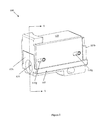
- Figure 2 is a perspective view of the device for adjusting the length of a lanyard shown in Figure 1 , in an assembled state in a released position, according to an exemplary embodiment.
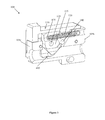
- Figure 3 is a perspective sectional view of the assembled device for adjusting the length of a lanyard shown in Figure 2 , in a released position, according to an exemplary embodiment.
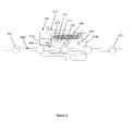
- Figure 4 is a side cross-sectional view of the assembled device for adjusting the length of a lanyard shown in Figure 2 , in a released position and having a lanyard cable disposed therein, according to an exemplary embodiment.
- Figure 5 is a perspective view of the device for adjusting the length of a lanyard shown in Figure 1 , in an assembled state in a locked position, according to an exemplary embodiment.
- Figure 6 is a bottom view of the assembled device for adjusting the length of a lanyard shown in Figure 5 , in a locked position, according to an exemplary embodiment.
- Figure 7 is a perspective sectional view of the assembled device for adjusting the length of a lanyard shown in Figure 5 , in a locked position, according to an exemplary embodiment.
- Figure 8 is a side cross-sectional view of the assembled device for adjusting the length of a lanyard shown in Figure 5 , in a locked position and having a lanyard cable disposed therein, according to an exemplary embodiment.
- Figure 9 is a perspective view of the device for adjusting the length of a lanyard shown in Figure 1 , in an assembled state, and coupled to a lanyard and a connector, according to an exemplary embodiment.
- a device described herein adjusts the length of a lanyard used in conjunction with release of an ordinance from an aircraft connector system.
- the device is generally capable of handling stresses associated with adjustment of the lanyard length.
- the device allows a user to quickly and easily adjust the length of a lanyard without the use of any tools.
- FIG. 1 is an exploded view showing the components of a device 100 for adjusting the length of a lanyard (not shown), according to an exemplary embodiment.
- the device 100 includes a housing 105.
- the housing 105 includes two side walls 105a, a bottom wall 105b, a top wall 105c, a base wall 105d, and a cavity 105e.
- Each of the side walls 105a includes an extension 105f extending along a length from the bottom wall 105b to the top wall 105c.
- Each side wall 105a also includes two holes 105g having a first diameter and two holes 105h, 105i having a second diameter. Each of the holes 105g are positioned on opposite sides of the holes 105h, 105i.
- the bottom wall 105b includes an aperture 105j sized appropriately to receive a retaining mechanism, such as a swaged ball, on a lanyard cable (not shown).
- the bottom wall 105b also includes a first portion 105k and a second portion 105m that extend past the side walls 105a of the housing 105.
- the first portion 105k includes a hole 105n extending from the bottom wall 105b towards the top wall 105c.
- the first portion 105k also includes a hole 105p extending a direction from one side wall 105a to the other side wall 105a.
- the second portion 105m includes an aperture 105q for coupling the device 100 to a connector (not shown).
- the device 100 includes a cover 110 configured to couple to the housing 105.
- the cover 110 includes two side walls 110a, an upper wall 110b, a top wall 110c, and an opening 110e.
- the opening 110e is configured to receive the side walls 105a and the first portion 105k of the housing 105 such that the cover 110 rests on the extensions 105f on the housing 105.
- Each of the side walls 110a includes two slots 110g that align with holes 105g when the cover 110 is coupled to the housing 105.
- the housing 105 and the cover 110 are fabricated from aerospace grade aluminum, or any other suitable lightweight material.
- the device 100 also includes a cam portion 115.
- the cam portion 115 includes two angled side walls 115a, a bottom wall 115b, and a top wall 115c.
- the top wall 115c includes a channel 115d extending lengthwise and parallel to the side walls 115a.
- the channel 115d is configured to receive a spring 120.
- the bottom wall 115b includes a recess 115e configured to receive a lanyard cable (not shown), but the recess 115e has a width that is smaller than the diameter of a swaged ball (not shown) on the lanyard cable.
- the cam portion 115 includes a hole 115h having a diameter similar to hole 105h of the housing 105.
- the cam portion 115 also includes holes 115j having a different diameter.
- the holes 115h, 115j extend from one side wall 115a to the other side wall 115a.
- the cam portion 115 further includes an angled pivot slot 115k formed by the angled side walls 115a.
- the device 100 further includes a spring 120.
- the spring 120 includes a looped first end 120a and a looped second end 120b.
- a release pin 125 couples the first end 120a of the spring 120 to the cam portion 115 via holes 115j. Once assembled, the release pin 125 extends past the side walls 115a of the cam portion 115 and into a groove (not shown) in the cover 110.
- the spring 120 is positioned within the channel 115d upon assembly of the device 100.
- the second end 120b of the spring 120 is positioned into hole 105n and coupled to hole 105p in the housing 105 via a dowel pin 130.
- the cam portion 115 is positioned within the cavity 105e of the housing 105.
- the cam portion 115 is coupled to the housing 105 by a cam pin 135.
- the cam pin 135 extends through holes 105h of the housing 105 and hole 115h of the cam portion 115.
- the cam portion 115 is rotatable within the housing 115 upon the cam pin 135.
- a load pin 140 extends through holes 105i of the housing 105 and rests within the angled pivot slot 115k of the cam portion 115. Once assembled, the load pin 140 restricts movement of the cam portion 115 to about 60 degrees.
- the cover 110 is coupled to the housing 105 by cover pins 145.
- the cover pins 145 extend through holes 105g of the housing 105 and slots 110g of the cover 110. Once the cover 110 is coupled to the housing 105, the cover pins 145 allow the cover 110 to move between a first position ( Figure 2 ) and a second position ( Figure 5 ) via slots 110g of the cover.
- the cam portion 115, the spring 120, the release pin 125, the dowel pin 130, the cam pin 135, the load pin 140, and the cover pins 145 are fabricated from corrosion-resistant steel, stainless steel, or any other suitable corrosion resistant material capable of withstanding the pulling force of a lanyard.
- Figure 2 is a perspective view of the device 100 assembled and in a released position, according to an exemplary embodiment.
- Figure 3 is a perspective sectional view, through a line A-A in Figure 2 , of the device 100 assembled and in the released position, according to an exemplary embodiment.
- Figure 4 is a side cross-sectional view of the device 100 assembled and in the released position, and having a lanyard cable 400 disposed therein, according to an exemplary embodiment.
- the lanyard cable 400 includes a number of swaged balls 405.
- the cable 400 has a diameter of about 1/16 inch and the swaged balls 405 have a diameter of about 0.19 inch.
- the lanyard cable 400 includes six swaged balls 405, each spaced apart along the cable 400 and separated by a distance of about 5/8 inch. In this configuration, the lanyard cable 400 can be adjusted up to about three inches.
- the diameter of the cable 400 and swaged balls 405 can be modified so long as the diameter of the swaged balls 405 is greater than the diameter of the cable 400.
- the swaged balls 405 can be spaced apart on the cable 400 any distance suitable for a particular application.
- the cover 110 in the released position, is shifted in a direction from the bottom wall 105b towards the top wall 105c of the housing 105. As a result, the cover 110 catches the release pin 125 and shifts the cam portion 115 in a counterclockwise direction about the cam pin 135.
- the rotation of the cam portion 115 is limited partly by the extension of the spring 120 and the length of the slots 110g of the cover 110.
- the load pin 140 also limits rotation of the cam portion 115 about pin 135 within the housing 105.
- an opening 410 is created such that the cable 400 having the swaged balls 405 can freely move within. A user can adjust the length of the cable 400 in this released position by moving the cable 400 to a desired position.
- Figure 5 is a perspective view of the device 100 assembled and in a locked position, according to an exemplary embodiment.
- Figure 6 is a bottom view of the device 100 assembled and in the locked position, according to an exemplary embodiment.
- Figure 7 is a perspective sectional view, through a line B-B in Figure 5 , of the device 100 assembled and in the locked position, according to an exemplary embodiment.
- Figure 8 is a side cross-sectional view of the device 100 assembled and in the locked position, and having the lanyard cable 400 disposed therein, according to an exemplary embodiment.
- Figure 9 is a perspective view of the device 100 assembled and coupled to the lanyard cable 400 and a lanyard ring 900 of a connector (not shown), according to an exemplary embodiment.
- the device 100 is coupled to a bail bar 905 via a loop in the lanyard cable 400.
- the cable 400 having swaged balls 405 extends through the device 100 and is coupled to a first end 900a of the lanyard ring 900.
- the device 100 is coupled to a second end 900b of the lanyard ring 900 via connecting ring 910 and aperture 105q.
- the connector attached to the lanyard ring 900 is coupled to an ordinance (not shown) to be released.
- the length of the lanyard cable 400 can be adjusted via simply shifting the cover 110, positioning an alternate swaged ball 405 within the device 100 by way of an end loop 915 of the lanyard cable 400, and locking the device 100. Therefore, the devices of the present invention allow a user to quickly and easily adjust the length of a lanyard cable.
- a user can shift the cover 110 to the released position ( Figures 2-4 ).
- the cam portion 115 is rotated such that the opening 410 allows both the cable 400 and swaged balls 405 to move therethrough.
- a user can make the lanyard longer or shorter by shifting the cable 400 to a desired position.
- the user pulls the cable 400 in a direction from the device 100 towards the bail bar 905.
- the user moves the cable 400 in a direction from the bail bar 905 towards the device 400 by pulling on the end loop 915.
- the user can adjust the cable 400 to a desired length of the lanyard and then allow the spring 120 to shift the cover 110 to the locked position ( Figures 5-8 ).
- the cam portion 115 rotates such that the bottom wall 115b extends into the opening 410 and prevents the swaged balls 405 from moving therethrough.
- the cable 400 is locked into place and the desired length of lanyard achieved.
Landscapes
- Engineering & Computer Science (AREA)
- General Engineering & Computer Science (AREA)
- Mechanical Engineering (AREA)
- Flexible Shafts (AREA)
- Details Of Connecting Devices For Male And Female Coupling (AREA)
- Light Guides In General And Applications Therefor (AREA)
Abstract
Description
- This application claims priority to
U.S. Provisional Application Serial No. 61/160,516 - The present invention relates generally to variable length lanyards. More particularly, the present invention is directed to a device or assembly for adjusting the length of a lanyard used in conjunction with aircraft umbilical connector release mechanisms.
- An aircraft carrying an ordinance, such as a weapon, typically utilizes an umbilical connector and a single loop contiguous lanyard for release of the ordinance. The connector interfaces between the ordinance and a lanyard cable, and the lanyard cable is looped around an aircraft mounted post, also known as a "bail bar."
- The ordinance mounts to the connector using a receptacle on the ordinance. The spatial orientation of the receptacle can vary from one ordinance to the next. Accordingly, the spatial orientation with respect to the bail bar varies from one ordinance to the next. As a result, problems may arise if there is too much slack in the lanyard. For example, impulse loading can occur on the lanyard cable, and the lanyard may break or the connector may be damaged. In addition, too much or too little slack in the lanyard may affect the release of the ordinance, or in the case of no slack, cause premature in-flight actuation of the connector.
- Most conventional lanyard designs do not allow for variations in the distance between the ordinance and the bail bar. Therefore, a number of lanyards having different lengths may be needed, so the lanyards are switched out based on the ordinance being utilized. The drawback to this conventional design is the difficulty for a user to quickly change the lanyard to suit a specific ordinance.
- Therefore, a need exists for a device or mechanism that allows a user to quickly adjust the length of a lanyard and is easy to use.
- Adjustment devices and systems described herein allow quick and efficient adjustment of a lanyard cable length. In one aspect, an adjustment assembly or device for a cable having at least two retaining mechanisms can include a base panel and four side walls defining a housing and arranged in a rectangular shape to form an interior cavity within the housing, a cover for covering the interior cavity, a cam device positioned in the interior cavity and coupled to the housing, and an elastic member, such as a spring, coupled to the housing and the cam device. One of the side walls and another opposing side wall each include an opening having a width or diameter that is greater than the width or diameter of the retaining mechanisms. The cover is slidably coupled to the housing, and is movable between a first position and a second position with respect to the housing. The cam device can be rotatably coupled to the housing by a cam pin. The rotation of the cam device within the interior cavity can be limited by a load pin. The cam device includes a stop mechanism, such as a recess, for retaining the cable, and a channel for receiving the elastic member. The elastic member is movable between a normal state and an extended state, and the cam device is movable between a locked position and an unlocked or released position. When the cover is in the first position, the elastic member is in the normal state, the cam device is in the locked position, and the stop mechanism prevents one of the retaining mechanisms from exiting the housing. The elastic member can be coupled to the cam device by a release pin that engages the cover when the cover is in the second position, and causes rotation of the cam device to the unlocked position. When the cover is in the second position, the elastic member is in the extended state, the cam device is in the unlocked position, and the retaining mechanisms are able to pass through the openings in the side walls and the interior cavity and the cable length can be adjusted.
- In another aspect, a system is defined that includes an adjustment assembly of the present invention, and a cable having at least two retaining mechanisms extending through the housing of the adjustment assembly. The retaining mechanisms can be shaped like a ball. The openings in the side walls of the housing have a diameter that is greater than the diameter of the ball retaining mechanisms. When the adjustment assembly is in the locked position, one of the retaining mechanisms is retained within the housing and the cable is prevented from passing therethrough. When the adjustment assembly is in the unlocked or released position, the retaining mechanisms can pass through the housing and the cable length can be adjusted.
- These and other aspects, objects, and features of the invention will become apparent to those having ordinary skill in the art upon consideration of the following detailed description of exemplary embodiments exemplifying the best mode for carrying out the invention as presently perceived.
-
Figure 1 is an exploded view of a device for adjusting the length of a lanyard, according to an exemplary embodiment. -
Figure 2 is a perspective view of the device for adjusting the length of a lanyard shown inFigure 1 , in an assembled state in a released position, according to an exemplary embodiment. -
Figure 3 is a perspective sectional view of the assembled device for adjusting the length of a lanyard shown inFigure 2 , in a released position, according to an exemplary embodiment. -
Figure 4 is a side cross-sectional view of the assembled device for adjusting the length of a lanyard shown inFigure 2 , in a released position and having a lanyard cable disposed therein, according to an exemplary embodiment. -
Figure 5 is a perspective view of the device for adjusting the length of a lanyard shown inFigure 1 , in an assembled state in a locked position, according to an exemplary embodiment. -
Figure 6 is a bottom view of the assembled device for adjusting the length of a lanyard shown inFigure 5 , in a locked position, according to an exemplary embodiment. -
Figure 7 is a perspective sectional view of the assembled device for adjusting the length of a lanyard shown inFigure 5 , in a locked position, according to an exemplary embodiment. -
Figure 8 is a side cross-sectional view of the assembled device for adjusting the length of a lanyard shown inFigure 5 , in a locked position and having a lanyard cable disposed therein, according to an exemplary embodiment. -
Figure 9 is a perspective view of the device for adjusting the length of a lanyard shown inFigure 1 , in an assembled state, and coupled to a lanyard and a connector, according to an exemplary embodiment. - A device described herein adjusts the length of a lanyard used in conjunction with release of an ordinance from an aircraft connector system. The device is generally capable of handling stresses associated with adjustment of the lanyard length. Generally, the device allows a user to quickly and easily adjust the length of a lanyard without the use of any tools.
-
Figure 1 is an exploded view showing the components of adevice 100 for adjusting the length of a lanyard (not shown), according to an exemplary embodiment. Thedevice 100 includes ahousing 105. Thehousing 105 includes twoside walls 105a, abottom wall 105b, atop wall 105c, abase wall 105d, and acavity 105e. Each of theside walls 105a includes anextension 105f extending along a length from thebottom wall 105b to thetop wall 105c. Eachside wall 105a also includes twoholes 105g having a first diameter and twoholes holes 105g are positioned on opposite sides of theholes - The
bottom wall 105b includes anaperture 105j sized appropriately to receive a retaining mechanism, such as a swaged ball, on a lanyard cable (not shown). Thebottom wall 105b also includes afirst portion 105k and asecond portion 105m that extend past theside walls 105a of thehousing 105. Thefirst portion 105k includes ahole 105n extending from thebottom wall 105b towards thetop wall 105c. Thefirst portion 105k also includes ahole 105p extending a direction from oneside wall 105a to theother side wall 105a. Thesecond portion 105m includes anaperture 105q for coupling thedevice 100 to a connector (not shown). - The
device 100 includes acover 110 configured to couple to thehousing 105. Thecover 110 includes twoside walls 110a, anupper wall 110b, atop wall 110c, and an opening 110e. The opening 110e is configured to receive theside walls 105a and thefirst portion 105k of thehousing 105 such that thecover 110 rests on theextensions 105f on thehousing 105. Each of theside walls 110a includes twoslots 110g that align withholes 105g when thecover 110 is coupled to thehousing 105. In certain embodiments, thehousing 105 and thecover 110 are fabricated from aerospace grade aluminum, or any other suitable lightweight material. - The
device 100 also includes acam portion 115. Thecam portion 115 includes twoangled side walls 115a, abottom wall 115b, and atop wall 115c. Thetop wall 115c includes achannel 115d extending lengthwise and parallel to theside walls 115a. Thechannel 115d is configured to receive aspring 120. Thebottom wall 115b includes arecess 115e configured to receive a lanyard cable (not shown), but therecess 115e has a width that is smaller than the diameter of a swaged ball (not shown) on the lanyard cable. Thecam portion 115 includes ahole 115h having a diameter similar tohole 105h of thehousing 105. Thecam portion 115 also includesholes 115j having a different diameter. Theholes side wall 115a to theother side wall 115a. Thecam portion 115 further includes anangled pivot slot 115k formed by theangled side walls 115a. - The
device 100 further includes aspring 120. Thespring 120 includes a loopedfirst end 120a and a loopedsecond end 120b. Arelease pin 125 couples thefirst end 120a of thespring 120 to thecam portion 115 viaholes 115j. Once assembled, therelease pin 125 extends past theside walls 115a of thecam portion 115 and into a groove (not shown) in thecover 110. Thespring 120 is positioned within thechannel 115d upon assembly of thedevice 100. Thesecond end 120b of thespring 120 is positioned intohole 105n and coupled to hole 105p in thehousing 105 via adowel pin 130. - The
cam portion 115 is positioned within thecavity 105e of thehousing 105. Thecam portion 115 is coupled to thehousing 105 by acam pin 135. Thecam pin 135 extends throughholes 105h of thehousing 105 andhole 115h of thecam portion 115. Thecam portion 115 is rotatable within thehousing 115 upon thecam pin 135. Aload pin 140 extends throughholes 105i of thehousing 105 and rests within theangled pivot slot 115k of thecam portion 115. Once assembled, theload pin 140 restricts movement of thecam portion 115 to about 60 degrees. - The
cover 110 is coupled to thehousing 105 by cover pins 145. The cover pins 145 extend throughholes 105g of thehousing 105 andslots 110g of thecover 110. Once thecover 110 is coupled to thehousing 105, the cover pins 145 allow thecover 110 to move between a first position (Figure 2 ) and a second position (Figure 5 ) viaslots 110g of the cover. - The
cam portion 115, thespring 120, therelease pin 125, thedowel pin 130, thecam pin 135, theload pin 140, and the cover pins 145 are fabricated from corrosion-resistant steel, stainless steel, or any other suitable corrosion resistant material capable of withstanding the pulling force of a lanyard. -
Figure 2 is a perspective view of thedevice 100 assembled and in a released position, according to an exemplary embodiment.Figure 3 is a perspective sectional view, through a line A-A inFigure 2 , of thedevice 100 assembled and in the released position, according to an exemplary embodiment.Figure 4 is a side cross-sectional view of thedevice 100 assembled and in the released position, and having alanyard cable 400 disposed therein, according to an exemplary embodiment. With respect toFigure 4 , thelanyard cable 400 includes a number of swagedballs 405. In certain embodiments, thecable 400 has a diameter of about 1/16 inch and the swagedballs 405 have a diameter of about 0.19 inch. In certain embodiments, thelanyard cable 400 includes six swagedballs 405, each spaced apart along thecable 400 and separated by a distance of about 5/8 inch. In this configuration, thelanyard cable 400 can be adjusted up to about three inches. One having ordinary skill in the art will recognize that the diameter of thecable 400 and swagedballs 405 can be modified so long as the diameter of the swagedballs 405 is greater than the diameter of thecable 400. In addition, the swagedballs 405 can be spaced apart on thecable 400 any distance suitable for a particular application. - With respect to
Figures 2-4 , in the released position, thecover 110 is shifted in a direction from thebottom wall 105b towards thetop wall 105c of thehousing 105. As a result, thecover 110 catches therelease pin 125 and shifts thecam portion 115 in a counterclockwise direction about thecam pin 135. The rotation of thecam portion 115 is limited partly by the extension of thespring 120 and the length of theslots 110g of thecover 110. In addition, theload pin 140 also limits rotation of thecam portion 115 aboutpin 135 within thehousing 105. When thecam portion 115 is shifted, anopening 410 is created such that thecable 400 having the swagedballs 405 can freely move within. A user can adjust the length of thecable 400 in this released position by moving thecable 400 to a desired position. -
Figure 5 is a perspective view of thedevice 100 assembled and in a locked position, according to an exemplary embodiment.Figure 6 is a bottom view of thedevice 100 assembled and in the locked position, according to an exemplary embodiment.Figure 7 is a perspective sectional view, through a line B-B inFigure 5 , of thedevice 100 assembled and in the locked position, according to an exemplary embodiment.Figure 8 is a side cross-sectional view of thedevice 100 assembled and in the locked position, and having thelanyard cable 400 disposed therein, according to an exemplary embodiment. - With respect to
Figures 5-8 , in the locked position, thecover 110 is shifted in a direction from thetop wall 105c towards thebottom wall 105b of thehousing 105. As a result, thecam portion 115 is rotated in a clockwise direction about thecam pin 135. The rotation of thecam portion 115 is limited partly by the length of theslots 110g of thecover 110 and the presence of theload pin 140. When thecam portion 115 is in this position, thebottom wall 115b extends intoopening 410. Thecable 400 is positioned within therecess 115e of thebottom wall 115b of thecam portion 115, but the swagedballs 405 are restricted from moving therein. Once a user has obtained a suitable length of lanyard, the user can locked thedevice 100 such that the position of thecable 400 cannot be adjusted until thedevice 100 is in a released position. -
Figure 9 is a perspective view of thedevice 100 assembled and coupled to thelanyard cable 400 and alanyard ring 900 of a connector (not shown), according to an exemplary embodiment. Thedevice 100 is coupled to abail bar 905 via a loop in thelanyard cable 400. Thecable 400 having swagedballs 405 extends through thedevice 100 and is coupled to afirst end 900a of thelanyard ring 900. Thedevice 100 is coupled to asecond end 900b of thelanyard ring 900 via connectingring 910 andaperture 105q. The connector attached to thelanyard ring 900 is coupled to an ordinance (not shown) to be released. Based on the ordinance coupled to the connector, the length of thelanyard cable 400 can be adjusted via simply shifting thecover 110, positioning an alternate swagedball 405 within thedevice 100 by way of anend loop 915 of thelanyard cable 400, and locking thedevice 100. Therefore, the devices of the present invention allow a user to quickly and easily adjust the length of a lanyard cable. - Generally, to adjust the length of a lanyard that is positioned within the
opening 410 of thedevice 100, a user can shift thecover 110 to the released position (Figures 2-4 ). In the released position, thecam portion 115 is rotated such that theopening 410 allows both thecable 400 and swagedballs 405 to move therethrough. A user can make the lanyard longer or shorter by shifting thecable 400 to a desired position. To increase the length of the lanyard, the user pulls thecable 400 in a direction from thedevice 100 towards thebail bar 905. To decrease the length of the lanyard, the user moves thecable 400 in a direction from thebail bar 905 towards thedevice 400 by pulling on theend loop 915. The user can adjust thecable 400 to a desired length of the lanyard and then allow thespring 120 to shift thecover 110 to the locked position (Figures 5-8 ). Once thecover 110 is in the locked position, thecam portion 115 rotates such that thebottom wall 115b extends into theopening 410 and prevents the swagedballs 405 from moving therethrough. As a result, thecable 400 is locked into place and the desired length of lanyard achieved. - Any spatial references herein, such as, for example, "top," "bottom," "upper," "lower," "above", "below," "rear," "between," "vertical," "angular," "beneath," etc., are for purpose of illustration only and do not limit the specific orientation or location of the described structure.
- Many modifications, features, and embodiments of the invention will become evident to those of ordinary skill in the art. It should be appreciated, therefore, that many aspects of the invention were described above by way of example only and are not intended as required or essential elements of the invention unless explicitly stated otherwise. Accordingly, it should be understood that the foregoing relates only to certain embodiments of the invention and that numerous changes may be made therein without departing from the spirit and scope of the invention. It should also be understood that the invention is not restricted to the illustrated embodiments and that various modifications can be made.
Claims (20)
- An adjustment assembly for a cable having at least two retaining mechanisms spaced apart thereon, the adjustment assembly comprising:a housing having a first opening and a second opening positioned on opposing walls of the housing, the housing defining an interior cavity;a cover for covering the interior cavity, wherein the cover is movable between a first position and a second position with respect to the housing; anda cam device positioned within the interior cavity and coupled to the housing,wherein the cam device is movable between a locked position and an unlocked position,
wherein when the cover is in the first position, the cam device is in the locked position, wherein a stop mechanism of the cam device prevents one of said retaining mechanisms from exiting the housing when the cam device is in the locked position,
wherein when the cover is in the second position, the cam device is in the unlocked position, and
wherein the first and second openings and the interior cavity provide a passageway to allow said retaining mechanisms to pass therethrough when the cam device is in the unlocked position. - The adjustment assembly of claim 1, further comprising a spring member having a first end and a second end, wherein the first end of the spring member is coupled to the housing and the second end of the spring member is coupled to the cam device, wherein the spring member is movable between a normal state and an extended state, wherein when the cover is in the first position, the spring member is in the normal state, and wherein when the cover is in the second position, the spring member is in the extended state.
- The adjustment assembly of claim 1, wherein the cam device further comprises a channel, wherein the spring member is positioned at least partially within the channel.
- The adjustment assembly of claim 1, wherein the second end of the spring member is coupled to the cam device by a release pin.
- The adjustment assembly of claim 4, wherein when the cover is in the second position, the cover engages the release pin and causes rotation of the cam device to the unlocked position.
- The adjustment assembly of claim 1, wherein the cam device is coupled to the housing by a cam pin, and wherein the cam device is rotatable about the cam pin.
- The adjustment assembly of claim 1, further comprising a load pin positioned adjacent to the cam device within the interior cavity, wherein the load pin restricts full rotation of the cam device.
- The adjustment assembly of claim 7, wherein the load pin restricts rotation of the cam device to about 60 degrees.
- The adjustment assembly of claim 1, wherein the stop mechanism is a recess in the cam device, wherein the recess has a width that is less than a width of said retaining mechanism.
- An adjustable length cable assembly system comprising:an adjustment assembly comprising:a housing having a first opening and a second opening positioned on opposing walls of the housing, the housing defining an interior cavity;a cover for covering the interior cavity, wherein the cover is movable between a first position and a second position with respect to the housing;a cam device positioned within the interior cavity and coupled to the housing, wherein the cam device includes a stop mechanism, wherein the cam device is movable between a locked position and a released position; anda cable having at least two retaining mechanisms spaced apart thereon, the cable extending through the first and second openings and the interior cavity;wherein when the cover is in the first position, the cam device is in the locked position and the stop mechanism retains one of the retaining mechanisms in place within the housing, wherein when the cover is in the second position, the cam device is in the released position and the first and second openings and the interior cavity provide a passageway to allow the retaining mechanisms to pass therethrough.
- The adjustment assembly of claim 10, further comprising an elastic member having a first end and a second end, wherein the first end of the elastic member is coupled to the housing and the second end of the elastic member is coupled to the cam device, wherein the elastic member is movable between a normal state and an extended state, wherein when the cover is in the first position, the elastic member is in the normal state, and wherein when the cover is in the second position, the elastic member is in the extended state.
- The adjustable length cable assembly system of claim 10, wherein the cam device further comprises a channel, wherein the elastic member is positioned at least partially within the channel.
- The adjustable length cable assembly system of claim 10, wherein the second end of the elastic member is coupled to the cam device by a release pin.
- The adjustable length cable assembly system of claim 13, wherein when the cover is in the second position, the cover engages the release pin and causes rotation of the cam device to the released position.
- The adjustable length cable assembly system of claim 10, wherein the retaining mechanism is a ball.
- The adjustable length cable assembly system of claim 15, wherein the openings in the first and second walls are circular and have a diameter greater than a diameter of the ball.
- The adjustable length cable assembly system of claim 10, wherein the cam device is coupled to the housing by a cam pin, and wherein the cam device is rotatable about the cam pin.
- The adjustable length cable assembly system of claim 10, further comprising a load pin positioned adjacent to the cam device within the interior cavity, wherein the load pin restricts full rotation of the cam device.
- The adjustable length cable assembly system of claim 10, wherein the stop mechanism is a recess in the cam device, wherein the recess has a width that is less than a width of said retaining mechanism.
- An adjustment device for a cable having at least two retaining mechanisms spaced apart thereon, the adjustment device comprising:a housing having a base panel and a plurality of walls that define an interior space,
wherein each of the walls comprises a first edge, a second opposing edge, and a substantially planar member disposed between the first and second edge,
wherein the first edge is disposed adjacent to the base panel and each wall extends out from the base panel in a substantially orthogonal direction,
wherein the plurality of walls comprises a first wall, a second wall opposing the first wall, two side walls extending from the first wall to the second wall, and an opening positioned in each of the first wall and the second wall,
wherein the openings are aligned, and
wherein the openings are sized to allow said retaining mechanisms to pass therethrough;a cover slidably coupled to the housing and covering the interior space, wherein the cover is movable between a first position and a second position with respect to the housing;a spring having a first end and a second end, wherein the first end of the spring is coupled to the housing; anda cam portion positioned within the interior space and rotatably coupled to the housing,
wherein the cam portion includes a channel and a recess,
wherein the spring is positioned at least partially within the channel,
wherein the second end of the spring is coupled to the cam portion,
wherein the spring is movable between a normal state and an extended state,
wherein the cam portion is movable between a locked position and an unlocked position, wherein the recess is sized to receive said cable,
wherein the recess is sized to prevent said retaining mechanism from being positioned therein when the cam portion is in the locked position,
wherein when the cover is in the first position, the spring is in the normal state and the cam portion is in the locked position, and
wherein when the cover is in the second position, the spring is in the extended state and the cam portion is in the unlocked position to provide a passageway allowing the retaining mechanisms to pass through the openings and the interior space.
Applications Claiming Priority (1)
| Application Number | Priority Date | Filing Date | Title |
|---|---|---|---|
| US16051609P | 2009-03-16 | 2009-03-16 |
Publications (3)
| Publication Number | Publication Date |
|---|---|
| EP2230419A2 true EP2230419A2 (en) | 2010-09-22 |
| EP2230419A3 EP2230419A3 (en) | 2011-07-13 |
| EP2230419B1 EP2230419B1 (en) | 2013-07-03 |
Family
ID=42272517
Family Applications (1)
| Application Number | Title | Priority Date | Filing Date |
|---|---|---|---|
| EP10156640.4A Active EP2230419B1 (en) | 2009-03-16 | 2010-03-16 | Adjustable length lanyard |
Country Status (2)
| Country | Link |
|---|---|
| US (1) | US8333357B2 (en) |
| EP (1) | EP2230419B1 (en) |
Cited By (1)
| Publication number | Priority date | Publication date | Assignee | Title |
|---|---|---|---|---|
| GB2509691A (en) * | 2012-10-22 | 2014-07-16 | Spinlock Ltd | Rope gripping device having a cam and base grip mounted in a module that is removably engaged in a housing |
Families Citing this family (8)
| Publication number | Priority date | Publication date | Assignee | Title |
|---|---|---|---|---|
| US8187014B2 (en) * | 2009-05-19 | 2012-05-29 | Cooper Technologies Company | Lanyard connector |
| US8935832B2 (en) * | 2012-04-04 | 2015-01-20 | Syn Yao Enterprise Co. Ltd. | Structure to secure curtain rope |
| US8695174B1 (en) * | 2013-02-25 | 2014-04-15 | Li-Ming Cheng | Anchor apparatus for bead chain of window covering |
| US10729201B1 (en) | 2013-03-01 | 2020-08-04 | Rlf Industries Llc | Impact protection apparatus |
| US20140247129A1 (en) | 2013-03-01 | 2014-09-04 | Ricardo Lewis de la Fuente | Impact awareness device |
| US9481461B1 (en) * | 2015-10-29 | 2016-11-01 | Cooper Technologies Company | Dual release lanyard connector |
| US10704623B2 (en) * | 2017-02-14 | 2020-07-07 | Cory Robert Mahana | Rope arrest-and-release device for use on utility poles |
| FR3097287B1 (en) * | 2019-06-13 | 2022-12-23 | Thales Sa | LOCKING DEVICE FOR AN OBJECT HANGING ON A CABLE |
Family Cites Families (42)
| Publication number | Priority date | Publication date | Assignee | Title |
|---|---|---|---|---|
| US3179994A (en) * | 1964-01-22 | 1965-04-27 | Meyer Machine Inc | Safety appliance |
| US3386530A (en) * | 1966-12-07 | 1968-06-04 | Meyer Machine Inc | Safety clamp device |
| US3492702A (en) * | 1968-04-29 | 1970-02-03 | Lawrence R Stafford | Line grip device |
| US3589052A (en) * | 1969-04-15 | 1971-06-29 | Harold M King | Automatic sinker |
| FR2163404B1 (en) * | 1971-12-15 | 1974-08-23 | Decauville Sa | |
| US3811155A (en) * | 1972-06-21 | 1974-05-21 | L Stafford | Rope grab assembly |
| US3840212A (en) * | 1972-12-27 | 1974-10-08 | Meyer Ind Inc | Safety apparatus for lowering tower equipment |
| US4071926A (en) * | 1974-05-09 | 1978-02-07 | D. B. Enterprises, Inc. | Safety device for ladder climbers |
| US3876036A (en) * | 1974-06-20 | 1975-04-08 | Db Enterprises | Rope grab safety device |
| GB1487428A (en) * | 1974-12-12 | 1977-09-28 | Barrow Hepburn Equip Ltd | Personal safety equipment |
| US4034828A (en) * | 1975-04-14 | 1977-07-12 | Rose Manufacturing Company | Shock absorbing cable connector |
| US4077094A (en) * | 1976-09-17 | 1978-03-07 | Swager William E | Clamping device for a rope, cable, annular bar, or the like |
| US4225012A (en) * | 1979-04-06 | 1980-09-30 | International Telephone And Telegraph Corporation | Safety clamp device and apparatus utilizing same |
| US4465011A (en) * | 1982-07-19 | 1984-08-14 | Schaefer Marine, Inc. | Halyard stopper |
| DE3307914C2 (en) * | 1983-03-05 | 1985-01-17 | Willy Habegger AG, Thun | Clamping device for ropes or the like |
| US4521000A (en) * | 1983-06-06 | 1985-06-04 | Dodge Jr Cleveland E | Bypassing double action rope grip |
| US4542884A (en) * | 1983-06-06 | 1985-09-24 | Dodge Jr Cleveland E | Removable double action rope grip |
| IL71719A (en) * | 1984-05-02 | 1992-08-18 | Dan Marom | Rescue and glider device |
| US4560029A (en) * | 1984-08-29 | 1985-12-24 | Wgm Safety Corp. | Security device |
| DK153677C (en) * | 1984-09-26 | 1988-12-27 | Berendsen Sophus Marine As | LOCKING MECHANISM FOR FIXING A ROPE, A LINE OR SIMILAR LONG STRENGTH, FLEXIBLE TOWING ORGANIZATION |
| US4657110A (en) * | 1984-12-10 | 1987-04-14 | D B Industries, Inc. | Inertia rope grab |
| US4813469A (en) * | 1986-07-02 | 1989-03-21 | Scott Kenneth W | Louver blind control |
| US4830340A (en) * | 1987-12-14 | 1989-05-16 | Willie Loree Franklin | Rope grip apparatus |
| DK159628C (en) * | 1988-01-21 | 1991-04-29 | Berendsen Sophus Marine As | LATCH MECHANISM FOR A ROPE, A LINE OR A SIMILAR ELEVATIVE LIVING BODY |
| US4958415A (en) * | 1989-06-07 | 1990-09-25 | Quality Chain Corp. | Connector for lateral cable of tire chains |
| DK163532C (en) * | 1989-10-20 | 1992-08-10 | Berendsen Sophus Marine As | LOCKING MECHANISM FOR RELEASABLE FIXING OF A ROPE, LINE, OR SIMILAR LONG STRENGTH BODY |
| US5156240A (en) * | 1991-05-31 | 1992-10-20 | Meyer Ostrobrod | Rope grab |
| US5265696A (en) * | 1992-01-31 | 1993-11-30 | D B Industries, Inc. | Ladder climbing safety clamp |
| FR2688815B1 (en) * | 1992-03-18 | 1994-06-10 | Komet | IMPROVEMENTS IN SAFETY DEVICES FOR WORKERS WORKING IN HIGH AREAS. |
| FR2720283B1 (en) * | 1994-04-21 | 1996-08-23 | Froment Sa | Anti-fall device locks automatically on a safety rope. |
| GB2293193A (en) | 1994-09-19 | 1996-03-20 | Latchways Ltd | Fall arrest device |
| US5855251A (en) * | 1997-01-22 | 1999-01-05 | Deuer; Joseph F. | Security device for use with a safety line |
| US5924522A (en) * | 1997-05-16 | 1999-07-20 | Ostrobrod; Meyer | Cable grab |
| FR2780656B1 (en) * | 1998-07-03 | 2001-08-03 | Dalloz Fall Prot | ANTI-FALL APPARATUS ON A VERTICAL CABLE |
| US6095502A (en) * | 1999-04-15 | 2000-08-01 | Dodge, Jr.; Cleveland | Line grip with elongated cams |
| US6948594B2 (en) * | 2001-11-16 | 2005-09-27 | Tiffin Scenic Design, Inc. | Rope locking device with automatic safety mechanism |
| DE102004016623B3 (en) | 2004-04-03 | 2005-12-22 | Al-Ko Kober Ag | Control cable adjuster for parking brake, has pressing member which exerts force on clamping piece in direction of pulling member and locking mechanism |
| US20060054386A1 (en) * | 2004-09-09 | 2006-03-16 | D B Industries, Inc. | Connector for a safety cable |
| US7165295B2 (en) * | 2004-09-10 | 2007-01-23 | J.R. Clancy, Incorporated | Rope lock with out-of-balance indicator and automatic lockout |
| US20060283315A1 (en) * | 2005-06-06 | 2006-12-21 | Blackburn Rick J | Weapon release cable retention device and method |
| US7222840B1 (en) * | 2006-03-21 | 2007-05-29 | Stepper Orval O | Rope-guiding device |
| AU2008201955B1 (en) | 2008-05-02 | 2009-02-05 | Kwikkee Pty Ltd | An Attachment Apparatus For A Choker Chain |
-
2010
- 2010-03-11 US US12/721,805 patent/US8333357B2/en active Active
- 2010-03-16 EP EP10156640.4A patent/EP2230419B1/en active Active
Non-Patent Citations (1)
| Title |
|---|
| None |
Cited By (2)
| Publication number | Priority date | Publication date | Assignee | Title |
|---|---|---|---|---|
| GB2509691A (en) * | 2012-10-22 | 2014-07-16 | Spinlock Ltd | Rope gripping device having a cam and base grip mounted in a module that is removably engaged in a housing |
| GB2509691B (en) * | 2012-10-22 | 2015-06-10 | Spinlock Ltd | Modular rope-gripping device |
Also Published As
| Publication number | Publication date |
|---|---|
| US20100230572A1 (en) | 2010-09-16 |
| US8333357B2 (en) | 2012-12-18 |
| EP2230419A3 (en) | 2011-07-13 |
| EP2230419B1 (en) | 2013-07-03 |
Similar Documents
| Publication | Publication Date | Title |
|---|---|---|
| US8333357B2 (en) | Adjustable length lanyard | |
| US8935875B2 (en) | Articulating mount for weapon accessory | |
| US5595410A (en) | Quick-release locking device for telescoping member | |
| EP1927767B1 (en) | Improved safety carabiner | |
| US10526064B2 (en) | Actuating system for an actuatable door and an actuatable door having such an actuating system | |
| US9534428B2 (en) | Hood latch having dual unlocking function | |
| EP1305548B1 (en) | Adjustable tripod assembly | |
| US6601274B2 (en) | Static line snap | |
| US20150231423A1 (en) | Connector | |
| US10201720B2 (en) | Safety line traveller | |
| EP3678507B1 (en) | Harness connector | |
| MX2010011858A (en) | Locking clamp. | |
| EP2777772A2 (en) | Systems for assisted braking belay with a lever disengagement mechanism | |
| EP1143188A2 (en) | Tube connecting device | |
| US20190069644A1 (en) | Harness Connector | |
| US12179047B2 (en) | Horizontal lifeline shuttle apparatus | |
| CA3081312C (en) | Latching loader mechanism with gated feed | |
| EP3317175B1 (en) | Remote control lever assembly | |
| EP2963208B1 (en) | Lock for portable generators | |
| US11524185B2 (en) | Closure system | |
| EP1469144B1 (en) | Ballistic shelter | |
| EP3249243B1 (en) | Breakaway retention device | |
| KR102496022B1 (en) | Joy stick lever assembly | |
| EP2783598B1 (en) | Furniture item with coupling device | |
| US8016327B2 (en) | Bifurcated latching system |
Legal Events
| Date | Code | Title | Description |
|---|---|---|---|
| PUAI | Public reference made under article 153(3) epc to a published international application that has entered the european phase |
Free format text: ORIGINAL CODE: 0009012 |
|
| AK | Designated contracting states |
Kind code of ref document: A2 Designated state(s): AT BE BG CH CY CZ DE DK EE ES FI FR GB GR HR HU IE IS IT LI LT LU LV MC MK MT NL NO PL PT RO SE SI SK SM TR |
|
| AX | Request for extension of the european patent |
Extension state: AL BA ME RS |
|
| PUAL | Search report despatched |
Free format text: ORIGINAL CODE: 0009013 |
|
| AK | Designated contracting states |
Kind code of ref document: A3 Designated state(s): AT BE BG CH CY CZ DE DK EE ES FI FR GB GR HR HU IE IS IT LI LT LU LV MC MK MT NL NO PL PT RO SE SI SK SM TR |
|
| AX | Request for extension of the european patent |
Extension state: AL BA ME RS |
|
| 17P | Request for examination filed |
Effective date: 20120113 |
|
| 17Q | First examination report despatched |
Effective date: 20120302 |
|
| RIC1 | Information provided on ipc code assigned before grant |
Ipc: F16G 11/10 20060101ALN20120713BHEP Ipc: F16G 11/04 20060101AFI20120713BHEP |
|
| RIC1 | Information provided on ipc code assigned before grant |
Ipc: F16G 11/04 20060101AFI20120911BHEP Ipc: F16G 11/10 20060101ALN20120911BHEP |
|
| RIC1 | Information provided on ipc code assigned before grant |
Ipc: F16G 11/04 20060101AFI20121018BHEP Ipc: F16G 11/10 20060101ALN20121018BHEP |
|
| GRAP | Despatch of communication of intention to grant a patent |
Free format text: ORIGINAL CODE: EPIDOSNIGR1 |
|
| RIC1 | Information provided on ipc code assigned before grant |
Ipc: F16G 11/10 20060101ALN20121026BHEP Ipc: F16G 11/04 20060101AFI20121026BHEP |
|
| GRAP | Despatch of communication of intention to grant a patent |
Free format text: ORIGINAL CODE: EPIDOSNIGR1 |
|
| GRAS | Grant fee paid |
Free format text: ORIGINAL CODE: EPIDOSNIGR3 |
|
| INTG | Intention to grant announced |
Effective date: 20130503 |
|
| RIC1 | Information provided on ipc code assigned before grant |
Ipc: F16G 11/10 20060101ALN20130419BHEP Ipc: F16G 11/04 20060101AFI20130419BHEP |
|
| GRAA | (expected) grant |
Free format text: ORIGINAL CODE: 0009210 |
|
| AK | Designated contracting states |
Kind code of ref document: B1 Designated state(s): AT BE BG CH CY CZ DE DK EE ES FI FR GB GR HR HU IE IS IT LI LT LU LV MC MK MT NL NO PL PT RO SE SI SK SM TR |
|
| REG | Reference to a national code |
Ref country code: GB Ref legal event code: FG4D |
|
| REG | Reference to a national code |
Ref country code: CH Ref legal event code: EP Ref country code: AT Ref legal event code: REF Ref document number: 619971 Country of ref document: AT Kind code of ref document: T Effective date: 20130715 |
|
| REG | Reference to a national code |
Ref country code: IE Ref legal event code: FG4D |
|
| REG | Reference to a national code |
Ref country code: DE Ref legal event code: R096 Ref document number: 602010008145 Country of ref document: DE Effective date: 20130905 |
|
| PG25 | Lapsed in a contracting state [announced via postgrant information from national office to epo] |
Ref country code: SI Free format text: LAPSE BECAUSE OF FAILURE TO SUBMIT A TRANSLATION OF THE DESCRIPTION OR TO PAY THE FEE WITHIN THE PRESCRIBED TIME-LIMIT Effective date: 20130703 |
|
| REG | Reference to a national code |
Ref country code: AT Ref legal event code: MK05 Ref document number: 619971 Country of ref document: AT Kind code of ref document: T Effective date: 20130703 |
|
| REG | Reference to a national code |
Ref country code: NL Ref legal event code: VDEP Effective date: 20130703 |
|
| REG | Reference to a national code |
Ref country code: LT Ref legal event code: MG4D |
|
| PG25 | Lapsed in a contracting state [announced via postgrant information from national office to epo] |
Ref country code: AT Free format text: LAPSE BECAUSE OF FAILURE TO SUBMIT A TRANSLATION OF THE DESCRIPTION OR TO PAY THE FEE WITHIN THE PRESCRIBED TIME-LIMIT Effective date: 20130703 Ref country code: NO Free format text: LAPSE BECAUSE OF FAILURE TO SUBMIT A TRANSLATION OF THE DESCRIPTION OR TO PAY THE FEE WITHIN THE PRESCRIBED TIME-LIMIT Effective date: 20131003 Ref country code: PT Free format text: LAPSE BECAUSE OF FAILURE TO SUBMIT A TRANSLATION OF THE DESCRIPTION OR TO PAY THE FEE WITHIN THE PRESCRIBED TIME-LIMIT Effective date: 20131104 Ref country code: BE Free format text: LAPSE BECAUSE OF FAILURE TO SUBMIT A TRANSLATION OF THE DESCRIPTION OR TO PAY THE FEE WITHIN THE PRESCRIBED TIME-LIMIT Effective date: 20130703 Ref country code: SE Free format text: LAPSE BECAUSE OF FAILURE TO SUBMIT A TRANSLATION OF THE DESCRIPTION OR TO PAY THE FEE WITHIN THE PRESCRIBED TIME-LIMIT Effective date: 20130703 Ref country code: IS Free format text: LAPSE BECAUSE OF FAILURE TO SUBMIT A TRANSLATION OF THE DESCRIPTION OR TO PAY THE FEE WITHIN THE PRESCRIBED TIME-LIMIT Effective date: 20131103 Ref country code: HR Free format text: LAPSE BECAUSE OF FAILURE TO SUBMIT A TRANSLATION OF THE DESCRIPTION OR TO PAY THE FEE WITHIN THE PRESCRIBED TIME-LIMIT Effective date: 20130703 Ref country code: CY Free format text: LAPSE BECAUSE OF FAILURE TO SUBMIT A TRANSLATION OF THE DESCRIPTION OR TO PAY THE FEE WITHIN THE PRESCRIBED TIME-LIMIT Effective date: 20130904 Ref country code: LT Free format text: LAPSE BECAUSE OF FAILURE TO SUBMIT A TRANSLATION OF THE DESCRIPTION OR TO PAY THE FEE WITHIN THE PRESCRIBED TIME-LIMIT Effective date: 20130703 |
|
| PG25 | Lapsed in a contracting state [announced via postgrant information from national office to epo] |
Ref country code: GR Free format text: LAPSE BECAUSE OF FAILURE TO SUBMIT A TRANSLATION OF THE DESCRIPTION OR TO PAY THE FEE WITHIN THE PRESCRIBED TIME-LIMIT Effective date: 20131004 Ref country code: PL Free format text: LAPSE BECAUSE OF FAILURE TO SUBMIT A TRANSLATION OF THE DESCRIPTION OR TO PAY THE FEE WITHIN THE PRESCRIBED TIME-LIMIT Effective date: 20130703 Ref country code: NL Free format text: LAPSE BECAUSE OF FAILURE TO SUBMIT A TRANSLATION OF THE DESCRIPTION OR TO PAY THE FEE WITHIN THE PRESCRIBED TIME-LIMIT Effective date: 20130703 Ref country code: LV Free format text: LAPSE BECAUSE OF FAILURE TO SUBMIT A TRANSLATION OF THE DESCRIPTION OR TO PAY THE FEE WITHIN THE PRESCRIBED TIME-LIMIT Effective date: 20130703 Ref country code: FI Free format text: LAPSE BECAUSE OF FAILURE TO SUBMIT A TRANSLATION OF THE DESCRIPTION OR TO PAY THE FEE WITHIN THE PRESCRIBED TIME-LIMIT Effective date: 20130703 Ref country code: ES Free format text: LAPSE BECAUSE OF FAILURE TO SUBMIT A TRANSLATION OF THE DESCRIPTION OR TO PAY THE FEE WITHIN THE PRESCRIBED TIME-LIMIT Effective date: 20131014 |
|
| PG25 | Lapsed in a contracting state [announced via postgrant information from national office to epo] |
Ref country code: CY Free format text: LAPSE BECAUSE OF FAILURE TO SUBMIT A TRANSLATION OF THE DESCRIPTION OR TO PAY THE FEE WITHIN THE PRESCRIBED TIME-LIMIT Effective date: 20130703 |
|
| PG25 | Lapsed in a contracting state [announced via postgrant information from national office to epo] |
Ref country code: DK Free format text: LAPSE BECAUSE OF FAILURE TO SUBMIT A TRANSLATION OF THE DESCRIPTION OR TO PAY THE FEE WITHIN THE PRESCRIBED TIME-LIMIT Effective date: 20130703 Ref country code: RO Free format text: LAPSE BECAUSE OF FAILURE TO SUBMIT A TRANSLATION OF THE DESCRIPTION OR TO PAY THE FEE WITHIN THE PRESCRIBED TIME-LIMIT Effective date: 20130703 Ref country code: SK Free format text: LAPSE BECAUSE OF FAILURE TO SUBMIT A TRANSLATION OF THE DESCRIPTION OR TO PAY THE FEE WITHIN THE PRESCRIBED TIME-LIMIT Effective date: 20130703 Ref country code: EE Free format text: LAPSE BECAUSE OF FAILURE TO SUBMIT A TRANSLATION OF THE DESCRIPTION OR TO PAY THE FEE WITHIN THE PRESCRIBED TIME-LIMIT Effective date: 20130703 Ref country code: CZ Free format text: LAPSE BECAUSE OF FAILURE TO SUBMIT A TRANSLATION OF THE DESCRIPTION OR TO PAY THE FEE WITHIN THE PRESCRIBED TIME-LIMIT Effective date: 20130703 |
|
| PLBE | No opposition filed within time limit |
Free format text: ORIGINAL CODE: 0009261 |
|
| STAA | Information on the status of an ep patent application or granted ep patent |
Free format text: STATUS: NO OPPOSITION FILED WITHIN TIME LIMIT |
|
| 26N | No opposition filed |
Effective date: 20140404 |
|
| REG | Reference to a national code |
Ref country code: DE Ref legal event code: R097 Ref document number: 602010008145 Country of ref document: DE Effective date: 20140404 |
|
| PG25 | Lapsed in a contracting state [announced via postgrant information from national office to epo] |
Ref country code: LU Free format text: LAPSE BECAUSE OF FAILURE TO SUBMIT A TRANSLATION OF THE DESCRIPTION OR TO PAY THE FEE WITHIN THE PRESCRIBED TIME-LIMIT Effective date: 20140316 |
|
| REG | Reference to a national code |
Ref country code: CH Ref legal event code: PL |
|
| REG | Reference to a national code |
Ref country code: IE Ref legal event code: MM4A |
|
| PG25 | Lapsed in a contracting state [announced via postgrant information from national office to epo] |
Ref country code: CH Free format text: LAPSE BECAUSE OF NON-PAYMENT OF DUE FEES Effective date: 20140331 Ref country code: LI Free format text: LAPSE BECAUSE OF NON-PAYMENT OF DUE FEES Effective date: 20140331 Ref country code: IE Free format text: LAPSE BECAUSE OF NON-PAYMENT OF DUE FEES Effective date: 20140316 |
|
| REG | Reference to a national code |
Ref country code: FR Ref legal event code: PLFP Year of fee payment: 7 |
|
| PG25 | Lapsed in a contracting state [announced via postgrant information from national office to epo] |
Ref country code: MT Free format text: LAPSE BECAUSE OF FAILURE TO SUBMIT A TRANSLATION OF THE DESCRIPTION OR TO PAY THE FEE WITHIN THE PRESCRIBED TIME-LIMIT Effective date: 20130703 |
|
| PG25 | Lapsed in a contracting state [announced via postgrant information from national office to epo] |
Ref country code: SM Free format text: LAPSE BECAUSE OF FAILURE TO SUBMIT A TRANSLATION OF THE DESCRIPTION OR TO PAY THE FEE WITHIN THE PRESCRIBED TIME-LIMIT Effective date: 20130703 |
|
| PG25 | Lapsed in a contracting state [announced via postgrant information from national office to epo] |
Ref country code: MC Free format text: LAPSE BECAUSE OF FAILURE TO SUBMIT A TRANSLATION OF THE DESCRIPTION OR TO PAY THE FEE WITHIN THE PRESCRIBED TIME-LIMIT Effective date: 20130703 |
|
| PG25 | Lapsed in a contracting state [announced via postgrant information from national office to epo] |
Ref country code: BG Free format text: LAPSE BECAUSE OF FAILURE TO SUBMIT A TRANSLATION OF THE DESCRIPTION OR TO PAY THE FEE WITHIN THE PRESCRIBED TIME-LIMIT Effective date: 20130703 |
|
| PG25 | Lapsed in a contracting state [announced via postgrant information from national office to epo] |
Ref country code: TR Free format text: LAPSE BECAUSE OF FAILURE TO SUBMIT A TRANSLATION OF THE DESCRIPTION OR TO PAY THE FEE WITHIN THE PRESCRIBED TIME-LIMIT Effective date: 20130703 Ref country code: HU Free format text: LAPSE BECAUSE OF FAILURE TO SUBMIT A TRANSLATION OF THE DESCRIPTION OR TO PAY THE FEE WITHIN THE PRESCRIBED TIME-LIMIT; INVALID AB INITIO Effective date: 20100316 |
|
| REG | Reference to a national code |
Ref country code: FR Ref legal event code: PLFP Year of fee payment: 8 |
|
| REG | Reference to a national code |
Ref country code: FR Ref legal event code: PLFP Year of fee payment: 9 |
|
| PG25 | Lapsed in a contracting state [announced via postgrant information from national office to epo] |
Ref country code: MK Free format text: LAPSE BECAUSE OF FAILURE TO SUBMIT A TRANSLATION OF THE DESCRIPTION OR TO PAY THE FEE WITHIN THE PRESCRIBED TIME-LIMIT Effective date: 20130703 |
|
| REG | Reference to a national code |
Ref country code: GB Ref legal event code: 732E Free format text: REGISTERED BETWEEN 20181206 AND 20181212 |
|
| REG | Reference to a national code |
Ref country code: DE Ref legal event code: R081 Ref document number: 602010008145 Country of ref document: DE Owner name: EATON INTELLIGENT POWER LIMITED, IE Free format text: FORMER OWNER: COOPER TECHNOLOGIES CO., HOUSTON, TEX., US |
|
| P01 | Opt-out of the competence of the unified patent court (upc) registered |
Effective date: 20230521 |
|
| PGFP | Annual fee paid to national office [announced via postgrant information from national office to epo] |
Ref country code: GB Payment date: 20260220 Year of fee payment: 17 |
|
| PGFP | Annual fee paid to national office [announced via postgrant information from national office to epo] |
Ref country code: DE Payment date: 20260219 Year of fee payment: 17 |
|
| PGFP | Annual fee paid to national office [announced via postgrant information from national office to epo] |
Ref country code: IT Payment date: 20260219 Year of fee payment: 17 |
|
| PGFP | Annual fee paid to national office [announced via postgrant information from national office to epo] |
Ref country code: FR Payment date: 20260220 Year of fee payment: 17 |