EP2230054A1 - Robot movement regulating method, robot system, and robot movement regulating device - Google Patents
Robot movement regulating method, robot system, and robot movement regulating device Download PDFInfo
- Publication number
- EP2230054A1 EP2230054A1 EP08858016A EP08858016A EP2230054A1 EP 2230054 A1 EP2230054 A1 EP 2230054A1 EP 08858016 A EP08858016 A EP 08858016A EP 08858016 A EP08858016 A EP 08858016A EP 2230054 A1 EP2230054 A1 EP 2230054A1
- Authority
- EP
- European Patent Office
- Prior art keywords
- robot
- movement
- region
- arm
- axis
- Prior art date
- Legal status (The legal status is an assumption and is not a legal conclusion. Google has not performed a legal analysis and makes no representation as to the accuracy of the status listed.)
- Withdrawn
Links
Images





Classifications
-
- B—PERFORMING OPERATIONS; TRANSPORTING
- B25—HAND TOOLS; PORTABLE POWER-DRIVEN TOOLS; MANIPULATORS
- B25J—MANIPULATORS; CHAMBERS PROVIDED WITH MANIPULATION DEVICES
- B25J9/00—Program-controlled manipulators
- B25J9/16—Program controls
- B25J9/1674—Program controls characterised by safety, monitoring, diagnostic
- B25J9/1676—Avoiding collision or forbidden zones
-
- A—HUMAN NECESSITIES
- A61—MEDICAL OR VETERINARY SCIENCE; HYGIENE
- A61B—DIAGNOSIS; SURGERY; IDENTIFICATION
- A61B34/00—Computer-aided surgery; Manipulators or robots specially adapted for use in surgery
- A61B34/30—Surgical robots
-
- G—PHYSICS
- G05—CONTROLLING; REGULATING
- G05B—CONTROL OR REGULATING SYSTEMS IN GENERAL; FUNCTIONAL ELEMENTS OF SUCH SYSTEMS; MONITORING OR TESTING ARRANGEMENTS FOR SUCH SYSTEMS OR ELEMENTS
- G05B2219/00—Program-control systems
- G05B2219/30—Nc systems
- G05B2219/39—Robotics, robotics to robotics hand
- G05B2219/39098—Estimate stop, brake distance in predef time, then verify if in safe distance
-
- G—PHYSICS
- G05—CONTROLLING; REGULATING
- G05B—CONTROL OR REGULATING SYSTEMS IN GENERAL; FUNCTIONAL ELEMENTS OF SUCH SYSTEMS; MONITORING OR TESTING ARRANGEMENTS FOR SUCH SYSTEMS OR ELEMENTS
- G05B2219/00—Program-control systems
- G05B2219/30—Nc systems
- G05B2219/40—Robotics, robotics mapping to robotics vision
- G05B2219/40203—Detect position of operator, create non material barrier to protect operator
Definitions
- the present invention relates to a method and an apparatus for limiting movement of a robot and a robot system including the apparatus for limiting movement of a robot.
- Robots in particular, industrial robots are widely used, for example, in automobile assembly factories and the like.
- an operation program in which a set of instructions for making the robot move and perform an operation is described
- a safety barrier is usually disposed so as to surround the movement path of the robot with a predetermined margin so that an accident in which an operator or the like is endangered by the movement of the robot arm and the wrist can be avoided.
- the safety barrier is disposed outside the maximum movement range of the robot.
- a safety barrier outside the maximum movement range of the robot.
- a robot having a small movement range for performing an operation such as a robot for transporting small components
- disposing a safety barrier outside the maximum movement range of the robot increases the space occupied by the robot and results in a waste of space. Therefore, there are existing techniques for limiting the movement range of a robot by using computer control.
- Patent Document 1 describes a method for limiting movement of a robot.
- the method includes defining in a memory a region for limiting movement of the robot as a "virtual safety barrier", defining at least two three-dimensional regions each including a part of the robot including a workpiece and a tool, comparing predicted positions of the three-dimensional regions on a calculated path with the virtual safety barrier, and performing control so as to stop the robot if any of the predicted positions contact the virtual safety barrier.
- Reference Literature 1 Japanese Patent No. 3937080 (hereinafter referred to as Reference Literature 1), for example, describes a specific method for monitoring such a movement region.
- the method includes internally expressing an interference region, which is defined as a rectangular parallelepiped, as six circumscribed spheres each including four vertices of a corresponding one of the surfaces of the rectangular parallelepiped, calculating the distances between the centers of the circumscribed spheres and parts of arms, and determining whether there exists an interference state using the radii that have been set for the arms and the radii of the circumscribed spheres.
- the interference region can be checked in real time without applying an excessive load to the CPU of a controller.
- the movement range of a robot can be limited without depending on a safety barrier or the like, or a safety barrier may be disposed so as to encircle a smaller region. Therefore, the limited floor space of a factory or the like can be efficiently used.
- Patent Document 1 Japanese Unexamined Patent Application Publication No. 2004-322244 (pages 6 to 9, Fig. 1 )
- Patent Document 1 stops the robot if the predicted position of a robot on a calculated path is beyond the virtual safety barrier.
- coasting of the robot it is described that "although time (distance) for coasting movement and braking is necessary, the robot can safely stop because the robot can make prediction and thus recognize a position that is before the virtual safety barrier by a certain distance as a braking start position.” (See the paragraph [0013] of Patent Document 1. An overrun distance covered by the robot when the robot is urgently stopped, which will be referred to as “coasting” in the present application, is referred to as “coasting movement” in Patent Document 1.) However, full consideration is not given to coasting in Patent Document 1.
- An object of the present invention is to provide a method and an apparatus for limiting movement of a robot and a robot system including the apparatus with which floor space and the space of a factory or the like are efficiently used without wasting space by using the function described above.
- a method of limiting movement of a robot includes defining, in a memory, an arm-occupied region and a movement-forbidden region, the arm-occupied region being occupied by an arm of the robot and a tool attached to a wrist or a workpiece that is held, the movement-forbidden region being a region that the arm-occupied region is not permitted to enter; checking, when calculating a target position of the workpiece or the tool and generating a movement command for each axis of the robot for each calculation period, whether the arm-occupied region enters the movement-forbidden region, the arm-occupied region being based on the target position of the tool or the workpiece for a next calculation period; controlling the robot so as to stop movement of the robot if it is checked that the arm-occupied region enters the movement-forbidden region; calculating a predicted coasting position of each axis of the robot by estimating a coasting angle of each axis of
- a robot system which controls a robot so as to stop movement of the robot on a stop request, includes a robot and a robot controller that controls the robot, the robot controller including a memory that stores an arm-occupied region and a movement-forbidden region, the arm-occupied region being defined on the basis of an arm of the robot, a tool attached to a wrist of the robot, or a workpiece that is held, the movement-forbidden region being a region that the arm-occupied region is not permitted to enter, a target position calculation unit that calculates a movement target position of the tool or the workpiece for each calculation period and generates a movement command for each axis of the robot, a movement-forbidden region entry monitoring unit that checks whether the arm-occupied region enters the movement-forbidden region, the arm-occupied region being based on the movement target position of the tool or the workpiece that has been calculated by the target position calculation unit, and outputs a stop request to stop movement of the robot if it is checked that the arm-
- the robot controller is connected to a teach pendant including a display device and displays a message indicating that the robot is stopped when the robot controller performs stop control on the stop request to stop movement of the robot.
- the robot controller is connected to a teach pendant including a display device and, if a predetermined control method is set to continuous control, displays a message indicating that continuous control of the robot is performed without stopping the robot on the stop request.
- a robot system includes a robot and a robot controller that controls the robot, the robot controller including a target position calculation unit that calculates, for each calculation period, a movement target position of a tool attached to a wrist or a workpiece that is held and generates a movement command for each axis of the robot, a drive unit that moves the robot on the basis of the movement command, a memory that stores an arm-occupied region and a movement-forbidden region, the arm-occupied region being defined on the basis of an arm of the robot, a tool attached to a wrist of the robot, or a workpiece that is held, the movement-forbidden region being a region that the arm-occupied region is not permitted to enter, a present position detection unit that detects a present position of a motor by using a position detector included in each axis of the robot, calculates a present position of the robot from the present position of the motor, and stores the present position of the motor and the present position of the robot, a movement-forbidden region
- a robot movement limiting apparatus includes means for defining, in a memory, an arm-occupied region occupied by an arm of the robot and a tool attached to a wrist or a workpiece that is held; means for defining, in a memory, a movement-forbidden region being in which the arm-occupied region is not permitted to enter; means for obtaining a position of each axis of the robot at a predetermined period; means for calculating a velocity of each axis from the position of each axis of the robot that has been obtained and from the predetermined period, calculating a moment of inertia and a gravitational moment of each axis from an angle of each axis, and predicting a torque acting on each axis from the velocity, the moment of inertia, and the gravitational
- the movement region of the robot can be limited with consideration of coasting of the robot if an unexpected urgent stop occurs. Therefore, the robot does not enter the movement-forbidden region in any circumstances, so that the movement-forbidden region can be safely and correctly set.
- floor space and the space of factory can be efficiently utilized while ensuring safety of workers of the factory.
- an operator can easily check how the movement of the robot is being limited.
- the movement region monitoring device for monitoring the movement of the robot is independent from the robot controller. Therefore, the movement region monitoring device is not affected when the control of the robot is improved (upgraded). Safety in movement region monitoring is maintained irrespective of the control of the robot. Therefore, for example, customer's trust can be easily obtained by obtaining safety certification from an independent organization for the movement region monitoring device.
- Fig. 1 is a diagram illustrating a method for limiting movement of a robot and a robot system that uses the method according to the present invention.
- the robot is illustrated with lines.
- a physical safety barrier 10 is disposed on a floor of a factory, and a robot 1 is disposed in the physical safety barrier 10.
- the robot 1 includes a body 2 and three arms 3, 4, and 5.
- a tool 7 is attached to the arm 5 with a holding mechanism 6 therebetween. Examples of the tool 7 include a welding torch used for arc welding, a welding gun used for spot welding, and a hand for transporting an object.
- the arms 3, 4, and 5 are connected to each other through joints 8.
- a workpiece 9 is placed on the floor. Examples of the workpiece 9 include an object to be welded and an object to be transported.
- a controller 20 sends a necessary signal to the body 2.
- the arms 3, 4, and 5 move in a predetermined manner in accordance with a predetermined operation program.
- the holding mechanism 6 or the tool 7 moves along a desired path.
- a teach pendant 21 is connected to the controller 20. Teaching of the robot 1, rewriting of an operation program, and the like are performed using the teach pendant 21.
- a movement-forbidden region 50 for the robot 1 is set.
- the movement-forbidden region 50 is set any time when it is necessary to change the movement-forbidden region 50.
- the movement-forbidden region 50 is defined and set as a rectangular parallelepiped.
- the movement-forbidden region 50 is defined by inputting the coordinates of the vertices of the rectangular parallelepiped by using the teach pendant 21, or by moving the control points of the robot 1 by using the teach pendant 21 so as to specify vertices of the rectangular parallelepiped.
- the movement-forbidden region 50 is stored in a memory of the controller 20.
- the movement-forbidden region 50 can be defined as a plurality of regions.
- Spatial regions occupied by the arms 3, 4, and 5 of the robot 1 and the tool 7 are defined as arm-occupied regions A1, A2, A3, A4, A5, and A6.
- the arms 3, 4, and 5 are respectively defined as cylindrical regions A4, A5, and A6 each having a predetermined radius and an axis that is a straight line connecting the joints 8 to each other.
- the regions A1 and A2, each including a corresponding one of the joints 8, are each defined as a sphere having a predetermined radius and a center at a point on the axis of the joint 8 of the robot 1.
- the region A3 which includes the holding mechanism 6 and the tool 7 attached to the distal end of the arm 5, is defined as a sphere having a predetermined radius.
- These definitions of the arm-occupied regions A1 to A6 are stored in the memory of the controller 20.
- Each of the arm-occupied regions may be a sphere or a cylinder having an appropriate radius.
- margin of safety increases.
- space utilization decreases because it becomes necessary to define the movement-forbidden region 50 as a larger region. Otherwise, movement of the arm is limited.
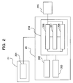
- Fig. 2 is a block diagram illustrating an embodiment of a method for controlling a robot, which is implemented in the controller 20.
- a teach/operation unit 201 calls and executes an operation program and performs a robot operation for teaching the robot.
- the teach/operation unit 201 also performs storing of taught data (the operation program and other information related to the operation) in a taught data storing area 202 and performs storing of various parameters in a parameter storing area 203.
- the parameter storing area 203 also stores the dimensions of parts of the arm, which are necessary for interpolation; specifications of the axes, such as the reduction ratios and motor constants, which are necessary for moving the axes of the robot; the radii of the arm-occupied regions A1 to A6; and coordinates and the like for defining the movement-forbidden region 50.
- the teach/operation unit 201 sends a robot movement request command to a movement command generating unit 204.
- a next target position calculation unit 206 calculates an interpolation point on a movement path of a robot as a next target position for each predetermined interpolation period, the movement path having been defined in the operation program.
- a movement-forbidden region entry monitoring unit 208 checks whether the next target position enters a movement-forbidden region.
- a predicted-coasting-position calculating unit 207 calculates a position (predicted coasting position) at which the robot will stop after coasting if the robot is urgently stopped while the robot is moving toward the next target position.
- the movement-forbidden region entry monitoring unit 208 checks whether the predicted coasting position enters the movement-forbidden region.
- the next target position calculation unit 206 sends to a drive unit 205 a command value for each axis of the robot for moving the robot to a calculated position.
- a stop request is sent to the drive unit 205.
- the drive unit 205 moves each axis of the robot 1 in accordance with the command value sent from the movement command generating unit 204.
- the drive unit 205 stops the robot 1 instead of moving the robot 1.
- Fig. 3 is a diagram illustrating movement of a robot in order to describe fundamental ideas of the present invention.
- the robot 1 is moving from a present position 301 to a next target position 302. If the robot 1 is urgently stopped at this moment, each axis coasts to some extent in accordance with the load at the moment and then stops. By predicting the coasting angle of each axis and adding the coasting angle to the next target position, a predicted coasting position 303 can be obtained.
- ⁇ s1 is the angle of a first axis 304 at the present position 301
- ⁇ e1 is the angle of the first axis 304 at the next target position 302.
- ⁇ d1 is the coasting angle when the robot 1 is urgently stopped under the load corresponding to the orientation at the next target position 302.
- the predicted coasting position 303 can be obtained by calculating ⁇ e1 + ⁇ d1. If an arm-occupied region enters the movement-forbidden region 50 when the robot 1 is at the predicted coasting position 303, the robot 1 is stopped before the robot 1 is moved to the next target position 302, so that the robot 1 is prevented from entering the movement-forbidden region 50 after coasting.
- the moment of inertia and the gravitational moment for the first axis 304 in the case of (b) are larger than those in the case of (a). Therefore, the coasting angle is larger in the case of (b), so that it can be predicted that the arm-occupied region of a wrist enters the movement-forbidden region 50 as illustrated in the figure. Thus, the robot 1 is stopped in the case of (b).
- Fig. 4 is a flowchart of a method implemented in the movement command generating unit 204 for limiting movement of a robot so that the robot does not interfere with the movement-forbidden region.
- the method according to the present invention will be described step by step.
- step So1 the next target position calculation unit 206 calculates the next target position (302 in Fig. 3 ) for each calculation period.
- the next target position includes the angle of each axis of the robot.
- the process proceeds to step S02.
- step S02 it is checked whether any of the arm-occupied regions A1 to A6 enter the movement-forbidden region 50 when the robot is at the next target position, which has been calculated in step S01.
- the movement-forbidden region entry monitoring unit 208 performs this check.
- the method used here includes defining the movement-forbidden region as a rectangular parallelepiped, representing the rectangular parallelepiped as six circumscribed spheres each passing through four vertices of a corresponding surface, calculating the distances between the centers of the circumscribed spheres and parts of the arms, and determining whether there exists an interference state using the radii that have been set for the arms and the radii of the circumscribed spheres.
- the movement-forbidden region 50 is defined by a plurality of regions. Similar checks are performed for all movement-forbidden regions. If an arm-occupied region enters any of the movement-forbidden regions, it is determined that the arm-occupied region "enters" the movement-forbidden region. If the determination is "enters", the process proceeds to step S12. Otherwise, the process proceeds to step S03.
- step S03 the velocity ⁇ i of each axis of the robot is calculated from the difference between the present position and the next target position and from the calculation period t.
- the predicted-coasting-position calculating unit 207 calculates the velocity.
- the process proceeds to step S04.
- step S04 the predicted-coasting-position calculating unit 207 calculates the inertia matrix J and the gravitational moment G that are generated around each axis of the robot at the next target position.
- the inertia matrix J is represented by an nxn matrix
- the gravitational moment G is represented by an n ⁇ 1 matrix.
- the inertia matrix and the gravitational moment of each axis can be calculated from the orientation of the robot by using any of various equations of motion. For example, well-known methods using the "Newton-Euler equation of motion" and “Lagrange equation of motion” are appropriate for real-time computing performed by a computer. Next, the process proceeds to step S05.
- step S05 the predicted-coasting-position calculating unit 207 calculates the energy Ui generated at each axis from the velocity ⁇ i, the inertia matrix J, and the gravitational moment G of each axis, which have been calculated in the steps up to and including step S04.
- a robot arm is a rotating body that rotates around each axis.
- the kinetic energy K of a rotating body is represented by the following equation.
- step S06 the predicted-coasting-position calculating unit 207 calculates the coasting angle of each axis when the robot 1 is urgently stopped.
- the braking torque Tbi is a characteristic of each axis that is determined by the capability of the mechanical brake of the servo motor, the dynamic brake of the servo amplifier, the regenerative braking, the friction drag of the reduction mechanism, and the like.
- the larger the braking torque the smaller the coasting angle of each axis. Therefore, the coasting angle of the i-th axis when a robot axis that is moving with a certain energy is urgently stopped can be calculated using the following equation.
- ⁇ di / Tb i U i
- the coasting angle ⁇ di of each axis is calculated using this equation.
- ⁇ d1 in Fig. 3(b) represents the coasting angle of the first axis.
- the set value of the braking torque of each axis has been stored in the parameter storing area 203 by using the teach pendant 21 or the like. Next, the process proceeds to step S07.
- a "predicted coasting position" is calculated on the basis of the coasting angle of each axis, which has been calculated in step S06.
- the predicted coasting position calculated here is a position that the robot 1 will reach if the robot 1 is urgently stopped at the next target position.
- the angle of the first axis at the predicted coasting position 303 is the sum of the angle ⁇ e1 of the first axis at the next target position 302 and the coasting angle ⁇ d1, which has been calculated in step S06.
- the process proceeds to step S08.
- step S08 it is checked whether the predicted coasting position 303 enters the movement-forbidden region.
- the method of checking is the same as that of step S02.
- the movement-forbidden region entry monitoring unit 208 performs this check. If the determination is "enters”, the process proceeds to step S09. Otherwise, the process proceeds to step S11.
- step S09 the process branches to stop control and continuous control in accordance with the control method that an operator has set as a parameter. If the control method is stop control, the process proceeds to step S12. If the control method is continuous control, the process proceeds to step S10.
- step S10 a message "continue movement” or a message having the same meaning and the step number of the operation program at which the predicted coasting position enters the movement-forbidden region in step S08 are displayed on the display of the teach pendant 21. Then, the process proceeds to step S11.
- step S11 a movement command for moving the robot 1 to the next target position, which has been calculated by the next target position calculation unit 206, is output to the drive unit 205, and the robot 1 is moved.
- step S12 the movement-forbidden region entry monitoring unit 208 sends a stop request to the drive unit 205.
- the drive unit 205 stops the movement of the robot 1.
- a message explaining the reason for stopping is displayed on the display of the teach pendant 21.
- a control method can be selected from “urgent stop” and "continue movement” when it is predicted that the coasting position will enter the movement-forbidden region (step S09).
- the operation program is played back while selecting the "continue movement”.
- This selection can be utilized so as to select "urgent stop” during actual production so that the robot 1 can be urgently stopped if the possibility of interference arises in an abnormal situation.
- a region in which the robot is allowed to move i.e., a "movement-allowed region” than to define a region that the robot is not allowed to enter. That is, a region surrounded by a safety barrier is defined.
- a similar effect is produced by defining a plurality of movement-forbidden regions that surround the movement-allowed region that has been defined.
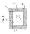
- Fig. 5 is a top view of a system in which a movement-allowed region 70 is defined as a rectangular parallelepiped that contains the robot 1.
- the controller When a user defines the movement-allowed region 70, the controller automatically generates a plurality of movement-forbidden regions 51 to 54 that are adjacent to the surfaces of the movement-allowed region 70, and stores the movement-forbidden regions 51 to 54 in the parameter storing area 203 beforehand.
- motion control that does not allow the robot to move outside the movement-allowed region 70 can be realized by using the method described above.
- a control apparatus may be independently provided so that the control apparatus monitors whether a robot enters a movement-forbidden region and stops the movement of the robot if the robot will enter the movement-forbidden region.
- Figs. 6 and 7 illustrate another embodiment of the present invention, which is an independent apparatus that performs such monitoring and stop control.
- Fig. 6 illustrates a system in which a movement region monitoring device 601 is added to the system illustrated in Fig. 2 .
- a present position detection unit 602 reads a motor position 605 of each axis, which is detected by a position detector such as an encoder, from the drive unit 205 for each predetermined monitoring period. From the motor position 605 of each axis, the present position of the robot (the position of a workpiece or a tool, also referred to as TCP) is calculated. A movement-forbidden region entry monitoring unit 604 checks whether the present position of the robot enters the movement-forbidden region. On the basis of the information about the motor position 605 detected by the present position detection unit 602, a predicted-coasting-position calculating unit 603 calculates the position at which the robot will stop after coasting if the robot is urgently stopped at this moment.
- the movement-forbidden region entry monitoring unit 604 checks whether the predicted coasting position the robot enters the movement-forbidden region. If the movement-forbidden region entry monitoring unit 604 detects that the robot enters the movement-forbidden region, the movement-forbidden region entry monitoring unit 604 outputs an urgent stop request 606, such as a power off signal, to the drive unit 205.
- Fig. 7 is a flowchart for limiting movement of a robot using the system illustrated in Fig. 6 so that the robot does not interfere with the movement-forbidden region. By using this figure, a method according to the present invention will be described step by step.
- step S101 the present position detection unit 602 detects the motor position 605 of each axis of the robot. Next, using the motor position 605 of each axis that has been detected, the present position of the robot is calculated. For subsequent processing, the present position of the motor of each axis (present position) and the previous position that has been previously detected (previous position) are stored. Next, the process proceeds to step S102.
- step S102 the movement-forbidden region entry monitoring unit 604 checks whether any of the arm-occupied regions A1 to A6 enter the movement-forbidden region 50 when the robot is at the present position that has been calculated in step S101.
- a specific method of entry monitoring a method the same as that used in step S02 of the flowchart of Fig. 4 can be used. If the determination is "enters”, the process proceeds to step S109. Otherwise, the process proceeds to step S103.
- step S103 the velocity ⁇ i of the each axis of the robot is calculated from the difference between the previous position and the present position of the motor of each axis and from the monitoring period.
- the index i denotes the number of axis.
- step S104 the inertia matrix J and the gravitational moment G that are generated around each axis of the robot at the present position of the motor of each axis are calculated.
- the predicted-coasting-position calculating unit 603 performs these calculations.
- the method is the same as that of step S04 in Fig. 4 .
- the process proceeds to step S105.
- step S105 the energy Ui generated at each axis is calculated from the velocity ⁇ i, the inertia matrix J, and the gravitational moment vector G of each axis, which have been calculated in the steps up to and including step S104.
- the predicted-coasting-position calculating unit 603 performs these calculations.
- the calculation method is the same as that of step S05 in Fig. 4 .
- the process proceeds to step S106.
- step S106 the coasting angle of each axis if the robot is urgently stopped when the motor of each axis is at the present position is calculated.
- the predicted-coasting-position calculating unit 603 performs these calculations.
- the calculation method is the same as that of step S06 of Fig. 4 .
- the process proceeds to step S107.
- step S107 a "predicted coasting position" is calculated by adding the coasting angle, which has been calculated in step S106, to the present position of the motor of each axis.
- the predicted-coasting-position calculating unit 603 performs these calculations.
- the calculation method is the same as that of step S07 in Fig. 4 .
- the process proceeds to step S108.
- step S108 it is checked whether the predicted coasting position enters the movement-forbidden region.
- the checking method is the same as that of step S102. If the determination is "enters", the process proceeds to step S109. Otherwise, the monitoring process for the present monitoring period finishes.
- step S109 an urgent stop request is sent to the drive unit 205.
- movement of a robot is predicted so that whether the robot enters a movement-forbidden region, which is a virtual safety barrier, is statically and dynamically monitored. Therefore, the movement region of the robot can be reliably limited.
- a sturdy safety barrier which has been used to prevent an unintentional deviation of a robot from a movement region
- the movement region of the robot can be limited with a simple barrier because the reliability is increased, so that preparation for introducing a robot can be simplified.
Landscapes
- Engineering & Computer Science (AREA)
- Health & Medical Sciences (AREA)
- Surgery (AREA)
- Robotics (AREA)
- Life Sciences & Earth Sciences (AREA)
- Heart & Thoracic Surgery (AREA)
- Nuclear Medicine, Radiotherapy & Molecular Imaging (AREA)
- Biomedical Technology (AREA)
- Mechanical Engineering (AREA)
- Medical Informatics (AREA)
- Molecular Biology (AREA)
- Animal Behavior & Ethology (AREA)
- General Health & Medical Sciences (AREA)
- Public Health (AREA)
- Veterinary Medicine (AREA)
- Numerical Control (AREA)
- Manipulator (AREA)
Abstract
Description
- The present invention relates to a method and an apparatus for limiting movement of a robot and a robot system including the apparatus for limiting movement of a robot.
- Robots, in particular, industrial robots are widely used, for example, in automobile assembly factories and the like.
When such a robot moves, an operation program (in which a set of instructions for making the robot move and perform an operation is described), which has been taught to and recorded in a memory of a controller, controls movement of a robot arm and a wrist (and a workpiece and a tool attached to the wrist) so as to move the robot arm and the wrist along a desired movement path so that they do not interfere with peripheral equipment and they do not make an unnecessary movement.
However, a safety barrier is usually disposed so as to surround the movement path of the robot with a predetermined margin so that an accident in which an operator or the like is endangered by the movement of the robot arm and the wrist can be avoided.
The safety barrier is disposed outside the maximum movement range of the robot. For a robot having a small movement range for performing an operation, such as a robot for transporting small components, disposing a safety barrier outside the maximum movement range of the robot increases the space occupied by the robot and results in a waste of space. Therefore, there are existing techniques for limiting the movement range of a robot by using computer control.
For example,Patent Document 1 describes a method for limiting movement of a robot. The method includes defining in a memory a region for limiting movement of the robot as a "virtual safety barrier", defining at least two three-dimensional regions each including a part of the robot including a workpiece and a tool, comparing predicted positions of the three-dimensional regions on a calculated path with the virtual safety barrier, and performing control so as to stop the robot if any of the predicted positions contact the virtual safety barrier.
Japanese Patent No.3937080
By using these techniques, the movement range of a robot can be limited without depending on a safety barrier or the like, or a safety barrier may be disposed so as to encircle a smaller region. Therefore, the limited floor space of a factory or the like can be efficiently used.
[Patent Document 1] Japanese Unexamined Patent Application Publication No.2004-322244 pages 6 to 9,Fig. 1 ) - The method described in
Patent Document 1 stops the robot if the predicted position of a robot on a calculated path is beyond the virtual safety barrier. Regarding coasting of the robot, it is described that "although time (distance) for coasting movement and braking is necessary, the robot can safely stop because the robot can make prediction and thus recognize a position that is before the virtual safety barrier by a certain distance as a braking start position." (See the paragraph [0013] ofPatent Document 1. An overrun distance covered by the robot when the robot is urgently stopped, which will be referred to as "coasting" in the present application, is referred to as "coasting movement" inPatent Document 1.)
However, full consideration is not given to coasting inPatent Document 1. Making a prediction with a sufficient margin in real time requires a very high CPU performance, which is unrealistic.
Even when a robot moves on a calculated path in a movement pattern so as not to contact the virtual safety barrier, if the robot is urgently stopped due to an accident (such as an urgent stop of a production line or a malfunction of a servo amplifier), the coasting angles of the axes are different from each other in accordance with the moment of inertia, the gravitational moment, and the braking capability. Thus, the position after coasting deviates from a predicted path that has been assumed. As a result, this position may be beyond the virtual safety barrier.
Therefore, when installing a robot, it is necessary to provide a large margin between the safety barrier and the virtual safety barrier with consideration of coasting, which results in a waste of space.
The present invention, which has been achieved in view of such problems, prevents a robot from entering a movement-forbidden region in any circumstances by immediately stopping the robot or raising an alarm so that an operation program is corrected, when it is possible that each axis will enter the movement-forbidden region after coasting in the case that the robot is urgently stopped. An object of the present invention is to provide a method and an apparatus for limiting movement of a robot and a robot system including the apparatus with which floor space and the space of a factory or the like are efficiently used without wasting space by using the function described above. Means for Solving the Problems - In order to solve the above problem, the present invention has the following structure.
According to the invention described inClaim 1, a method of limiting movement of a robot includes defining, in a memory, an arm-occupied region and a movement-forbidden region, the arm-occupied region being occupied by an arm of the robot and a tool attached to a wrist or a workpiece that is held, the movement-forbidden region being a region that the arm-occupied region is not permitted to enter; checking, when calculating a target position of the workpiece or the tool and generating a movement command for each axis of the robot for each calculation period, whether the arm-occupied region enters the movement-forbidden region, the arm-occupied region being based on the target position of the tool or the workpiece for a next calculation period; controlling the robot so as to stop movement of the robot if it is checked that the arm-occupied region enters the movement-forbidden region; calculating a predicted coasting position of each axis of the robot by estimating a coasting angle of each axis of the robot in a case that the robot is urgently stopped when the robot is moving on the basis of a movement command for moving the tool or the workpiece to the target position for the next calculation period and by adding the estimated coasting angle of each axis to the movement command for each axis for the next calculation period if it is checked that the arm-occupied region does not enter the movement-forbidden region; checking whether the arm-occupied region at the predicted coasting position of each axis enters the movement-forbidden region; and controlling the robot so as stop movement of the robot if it is checked that the arm-occupied region enters the predicted coasting position.
According to the invention described inClaim 2, a robot system, which controls a robot so as to stop movement of the robot on a stop request, includes a robot and a robot controller that controls the robot, the robot controller including a memory that stores an arm-occupied region and a movement-forbidden region, the arm-occupied region being defined on the basis of an arm of the robot, a tool attached to a wrist of the robot, or a workpiece that is held, the movement-forbidden region being a region that the arm-occupied region is not permitted to enter, a target position calculation unit that calculates a movement target position of the tool or the workpiece for each calculation period and generates a movement command for each axis of the robot, a movement-forbidden region entry monitoring unit that checks whether the arm-occupied region enters the movement-forbidden region, the arm-occupied region being based on the movement target position of the tool or the workpiece that has been calculated by the target position calculation unit, and outputs a stop request to stop movement of the robot if it is checked that the arm-occupied region enters the movement-forbidden region, and a drive unit that moves the robot, wherein the robot controller includes a predicted-coasting-position calculating unit that calculates a predicted coasting position of each axis of the robot and a coasting position of the tool or the workpiece when each axis is at the predicted coasting position by estimating a coasting angle of each axis of the robot in a case that the robot is urgently stopped when the robot is moving to the movement target position of the tool or the workpiece and by adding the estimated coasting angle of each axis to the movement command for each axis, and wherein the movement-forbidden region entry monitoring unit checks whether the arm-occupied region at the coasting position enters the movement-forbidden region, and outputs another stop request to stop movement of the robot if it is checked that the arm-occupied region at the coasting position enters the movement-forbidden region.
According to the invention described in Claim 3, the robot controller is connected to a teach pendant including a display device and displays a message indicating that the robot is stopped when the robot controller performs stop control on the stop request to stop movement of the robot.
According to the invention described in Claim 4, the robot controller is connected to a teach pendant including a display device and, if a predetermined control method is set to continuous control, displays a message indicating that continuous control of the robot is performed without stopping the robot on the stop request.
According to the invention described inClaim 5, a robot system includes a robot and a robot controller that controls the robot, the robot controller including a target position calculation unit that calculates, for each calculation period, a movement target position of a tool attached to a wrist or a workpiece that is held and generates a movement command for each axis of the robot, a drive unit that moves the robot on the basis of the movement command, a memory that stores an arm-occupied region and a movement-forbidden region, the arm-occupied region being defined on the basis of an arm of the robot, a tool attached to a wrist of the robot, or a workpiece that is held, the movement-forbidden region being a region that the arm-occupied region is not permitted to enter, a present position detection unit that detects a present position of a motor by using a position detector included in each axis of the robot, calculates a present position of the robot from the present position of the motor, and stores the present position of the motor and the present position of the robot, a movement-forbidden region entry monitoring unit that checks whether the arm-occupied region enters the movement-forbidden region, the arm-occupied region being based on the movement target position of the tool or the workpiece calculated by the target position calculation unit, and outputs a stop request to stop movement of the robot if it is checked that the arm-occupied region enters the movement-forbidden region, and a predicted-coasting-position calculating unit that calculates a predicted coasting position of each axis of the robot and a coasting position of the tool or the workpiece when each axis is at the predicted coasting position by estimating a coasting angle of each axis of the robot in a case that the robot is urgently stopped when the robot is moving to the movement target position of the tool or the workpiece and by adding the estimated coasting angle of each axis to the movement command for each axis, wherein the movement-forbidden region entry monitoring unit checks whether the arm-occupied region at the coasting position enters the movement-forbidden region, and outputs another stop request to stop movement of the robot if it is checked that the arm-occupied region at the coasting position enters the movement-forbidden region.
According to the invention described inClaim 6, the memory, the present position detection unit, the predicted-coasting-position calculating unit, and the movement-forbidden region entry monitoring unit are independent from the robot controller.
According to the invention described inClaim 7, a robot movement limiting apparatus includes means for defining, in a memory, an arm-occupied region occupied by an arm of the robot and a tool attached to a wrist or a workpiece that is held; means for defining, in a memory, a movement-forbidden region being in which the arm-occupied region is not permitted to enter; means for obtaining a position of each axis of the robot at a predetermined period; means for calculating a velocity of each axis from the position of each axis of the robot that has been obtained and from the predetermined period, calculating a moment of inertia and a gravitational moment of each axis from an angle of each axis, and predicting a torque acting on each axis from the velocity, the moment of inertia, and the gravitational moment of each axis; means for calculating a non-operating-state torque by subtracting, from the torque, Coulomb friction and viscous friction that have been preset for each axis and a braking torque generated by a brake mechanism, and predicting a coasting angle of each axis from the non-operating-state torque; means for calculating a predicted coasting position in a case that the robot is urgently stopped by adding the coasting angle to a present angle of each axis of the robot; means for checking whether the arm-occupied region at the predicted coasting position of each axis enters the movement-forbidden region; and means for controlling the robot so as stop movement of the robot if it is checked that the arm-occupied region enters the predicted coasting position. - According to the inventions described in
Claims
According to the inventions described in Claims 3 and 4, an operator can easily check how the movement of the robot is being limited.
According to the inventions described inClaims -
- [
Fig. 1] Fig. 1 is a diagram illustrating a method for limiting movement of a robot according to the present invention and a robot system that uses the method. - [
Fig. 2] Fig. 2 is a block diagram of the method for limiting movement of a robot according to the present invention. - [
Fig. 3] Fig. 3 is a diagram illustrating the method for limiting movement of a robot according to the present invention and a robot that uses the method. - [
Fig. 4] Fig. 4 is a flowchart of the method for limiting movement of a robot according to the present invention. - [
Fig. 5] Fig. 5 is a diagram illustrating the method for defining a movement-forbidden region by using a movement-allowed region. - [
Fig. 6] Fig. 6 is a block diagram of a second method for limiting movement of the robot according to the present invention. - [
Fig. 7] Fig. 7 is a flowchart of the second method for limiting movement of a robot according to the present invention. -
- 1
- robot
- 2
- body
- 3, 4, 5
- arm
- 6
- holding mechanism
- 7
- tool
- 8
- joint
- 9
- workpiece
- 10
- physical safety barrier
- 20
- controller
- 21
- teach pendant
- 50
- movement-forbidden region
- 51
- movement-forbidden region (1)
- 52
- movement-forbidden region (2)
- 53
- movement-forbidden region (3)
- 54
- movement-forbidden region (4)
- 70
- movement-allowed region
- 201
- teach/operation section
- 202
- taught data storing area
- 203
- parameter storing area
- 204
- movement command generating unit
- 205
- drive unit
- 206
- next target position calculation unit
- 207, 603
- predicted-coasting-position calculating unit
- 208, 604
- movement-forbidden region entry monitoring unit
- 301
- present position
- 302
- next target position
- 303
- predicted coasting position
- 304
- first axis
- 601
- movement region monitoring device
- 602
- present position detection unit
- 605
- motor position
- 606
- urgent stop request
- A1, A2, A3, A4, A5, A6
- arm-occupied region
- Hereinafter, embodiments of a method according to the present invention will be described with reference to the drawings.
-
Fig. 1 is a diagram illustrating a method for limiting movement of a robot and a robot system that uses the method according to the present invention. (The robot is illustrated with lines.) Aphysical safety barrier 10 is disposed on a floor of a factory, and arobot 1 is disposed in thephysical safety barrier 10.
In this example, therobot 1 includes abody 2 and threearms 3, 4, and 5. Atool 7 is attached to thearm 5 with aholding mechanism 6 therebetween. Examples of thetool 7 include a welding torch used for arc welding, a welding gun used for spot welding, and a hand for transporting an object. Thearms 3, 4, and 5 are connected to each other throughjoints 8.
A workpiece 9 is placed on the floor. Examples of the workpiece 9 include an object to be welded and an object to be transported.
Acontroller 20 sends a necessary signal to thebody 2. Thearms 3, 4, and 5 move in a predetermined manner in accordance with a predetermined operation program. Theholding mechanism 6 or thetool 7 moves along a desired path.
Ateach pendant 21 is connected to thecontroller 20. Teaching of therobot 1, rewriting of an operation program, and the like are performed using theteach pendant 21. - After the robot has been installed and set and before the robot is operated, a movement-forbidden
region 50 for therobot 1 is set. In addition to when the robot is installed, the movement-forbiddenregion 50 is set any time when it is necessary to change the movement-forbiddenregion 50. The movement-forbiddenregion 50 is defined and set as a rectangular parallelepiped. The movement-forbiddenregion 50 is defined by inputting the coordinates of the vertices of the rectangular parallelepiped by using theteach pendant 21, or by moving the control points of therobot 1 by using theteach pendant 21 so as to specify vertices of the rectangular parallelepiped. After the movement-forbiddenregion 50 has been defined, the movement-forbiddenregion 50 is stored in a memory of thecontroller 20. The movement-forbiddenregion 50 can be defined as a plurality of regions. - Spatial regions occupied by the
arms 3, 4, and 5 of therobot 1 and thetool 7 are defined as arm-occupied regions A1, A2, A3, A4, A5, and A6.
Thearms 3, 4, and 5 are respectively defined as cylindrical regions A4, A5, and A6 each having a predetermined radius and an axis that is a straight line connecting thejoints 8 to each other. The regions A1 and A2, each including a corresponding one of thejoints 8, are each defined as a sphere having a predetermined radius and a center at a point on the axis of thejoint 8 of therobot 1. As the point on the axis of one of thejoints 8, the intersection of "a straight line connecting thejoints 8 to each other", which is used when defining the regions A4, A5, and A6, and the axis of the one of thejoints 8 is usually used. The region A3, which includes theholding mechanism 6 and thetool 7 attached to the distal end of thearm 5, is defined as a sphere having a predetermined radius. These definitions of the arm-occupied regions A1 to A6 are stored in the memory of thecontroller 20.
Each of the arm-occupied regions may be a sphere or a cylinder having an appropriate radius. When an arm-occupied region is defined as a sphere or a cylinder having a larger radius, margin of safety increases. However, space utilization decreases because it becomes necessary to define the movement-forbiddenregion 50 as a larger region. Otherwise, movement of the arm is limited. -
Fig. 2 is a block diagram illustrating an embodiment of a method for controlling a robot, which is implemented in thecontroller 20.
In accordance with an operation by an operator on theteach pendant 21, a teach/operation unit 201 calls and executes an operation program and performs a robot operation for teaching the robot. The teach/operation unit 201 also performs storing of taught data (the operation program and other information related to the operation) in a taughtdata storing area 202 and performs storing of various parameters in aparameter storing area 203. Theparameter storing area 203 also stores the dimensions of parts of the arm, which are necessary for interpolation; specifications of the axes, such as the reduction ratios and motor constants, which are necessary for moving the axes of the robot; the radii of the arm-occupied regions A1 to A6; and coordinates and the like for defining the movement-forbiddenregion 50. - When an operator calls and executes the operation program or performs a robot operation for teaching the robot, the teach/
operation unit 201 sends a robot movement request command to a movementcommand generating unit 204. When the movementcommand generating unit 204 receives the robot movement request command, a next targetposition calculation unit 206 calculates an interpolation point on a movement path of a robot as a next target position for each predetermined interpolation period, the movement path having been defined in the operation program. A movement-forbidden regionentry monitoring unit 208 checks whether the next target position enters a movement-forbidden region. A predicted-coasting-position calculating unit 207 calculates a position (predicted coasting position) at which the robot will stop after coasting if the robot is urgently stopped while the robot is moving toward the next target position. The movement-forbidden regionentry monitoring unit 208 checks whether the predicted coasting position enters the movement-forbidden region. The next targetposition calculation unit 206 sends to a drive unit 205 a command value for each axis of the robot for moving the robot to a calculated position. However, when the movement-forbidden regionentry monitoring unit 208 detects entry to the movement-forbidden region, a stop request is sent to thedrive unit 205.
Thedrive unit 205 moves each axis of therobot 1 in accordance with the command value sent from the movementcommand generating unit 204. When thedrive unit 205 receives the stop request, thedrive unit 205 stops therobot 1 instead of moving therobot 1. -
Fig. 3 is a diagram illustrating movement of a robot in order to describe fundamental ideas of the present invention.
Therobot 1 is moving from apresent position 301 to anext target position 302. If therobot 1 is urgently stopped at this moment, each axis coasts to some extent in accordance with the load at the moment and then stops. By predicting the coasting angle of each axis and adding the coasting angle to the next target position, a predictedcoasting position 303 can be obtained.
InFig. 3(b) , θs1 is the angle of afirst axis 304 at thepresent position 301, and θe1 is the angle of thefirst axis 304 at thenext target position 302. θd1 is the coasting angle when therobot 1 is urgently stopped under the load corresponding to the orientation at thenext target position 302. The predictedcoasting position 303 can be obtained by calculating θe1 + θd1.
If an arm-occupied region enters the movement-forbiddenregion 50 when therobot 1 is at the predictedcoasting position 303, therobot 1 is stopped before therobot 1 is moved to thenext target position 302, so that therobot 1 is prevented from entering the movement-forbiddenregion 50 after coasting.
InFig. 3 , the moment of inertia and the gravitational moment for thefirst axis 304 in the case of (b) are larger than those in the case of (a). Therefore, the coasting angle is larger in the case of (b), so that it can be predicted that the arm-occupied region of a wrist enters the movement-forbiddenregion 50 as illustrated in the figure. Thus, therobot 1 is stopped in the case of (b). -
Fig. 4 is a flowchart of a method implemented in the movementcommand generating unit 204 for limiting movement of a robot so that the robot does not interfere with the movement-forbidden region. Referring to this figure, the method according to the present invention will be described step by step.
In this description, it is assumed that the robot has n axes. Basically, each step will be repeated for the first axis to n-th axis. The number of each axis will be denoted by the index i. (For example, i = 1 ... 6 for a six-axis robot.) - In step So1, the next target
position calculation unit 206 calculates the next target position (302 inFig. 3 ) for each calculation period. The next target position includes the angle of each axis of the robot. Next, the process proceeds to step S02. - In step S02, it is checked whether any of the arm-occupied regions A1 to A6 enter the movement-forbidden
region 50 when the robot is at the next target position, which has been calculated in step S01. The movement-forbidden regionentry monitoring unit 208 performs this check.
There are various methods of entry monitoring. As with the method describe inReference Literature 1, the method used here includes defining the movement-forbidden region as a rectangular parallelepiped, representing the rectangular parallelepiped as six circumscribed spheres each passing through four vertices of a corresponding surface, calculating the distances between the centers of the circumscribed spheres and parts of the arms, and determining whether there exists an interference state using the radii that have been set for the arms and the radii of the circumscribed spheres.
When the movement-forbiddenregion 50 is defined by a plurality of regions, similar checks are performed for all movement-forbidden regions. If an arm-occupied region enters any of the movement-forbidden regions, it is determined that the arm-occupied region "enters" the movement-forbidden region.
If the determination is "enters", the process proceeds to step S12. Otherwise, the process proceeds to step S03. - In step S03, the velocity ωi of each axis of the robot is calculated from the difference between the present position and the next target position and from the calculation period t.
The predicted-coasting-position calculating unit 207 calculates the velocity.
For example, the velocity ω1 of the first axis inFig. 3(b) is calculated using the following equation:
where θs1 is the angle of the first axis at the present position, and θe1 is the angle of the first axis at the next target position as illustrated inFig. 3 .
Likewise, the velocity ωi is calculated for each of other axes (second to n-th axes). That is,
Next, the process proceeds to step S04. - In step S04, the predicted-coasting-
position calculating unit 207 calculates the inertia matrix J and the gravitational moment G that are generated around each axis of the robot at the next target position.
For the robot having n axes, the inertia matrix J is represented by an nxn matrix, and the gravitational moment G is represented by an n×1 matrix. -

The inertia matrix and the gravitational moment of each axis of the robot can be calculated from the mass, the center of gravity, the shape moment of parts of the arms, which are divided by the joints, and from the angle of each axis of the robot. The mass, the center of gravity, and the shape moment of each part of the arms are stored beforehand in theparameter storing area 203.
The inertia matrix and the gravitational moment of each axis can be calculated from the orientation of the robot by using any of various equations of motion. For example, well-known methods using the "Newton-Euler equation of motion" and "Lagrange equation of motion" are appropriate for real-time computing performed by a computer. Next, the process proceeds to step S05. - In step S05, the predicted-coasting-
position calculating unit 207 calculates the energy Ui generated at each axis from the velocity ωi, the inertia matrix J, and the gravitational moment G of each axis, which have been calculated in the steps up to and including step S04.
The total energy acting on a rotating body is represented by the following equation:
where U is the total energy, K is the kinetic energy, and P is the potential energy.
In most cases, a robot arm is a rotating body that rotates around each axis. The kinetic energy K of a rotating body is represented by the following equation. -

The potential energy P is equal to the gravitational moment G.
Therefore, the energy Ui of the i-th axis can be calculated using the following equation. -

- In step S06, the predicted-coasting-
position calculating unit 207 calculates the coasting angle of each axis when therobot 1 is urgently stopped. The relationship among the energy generated at the i-th axis, the braking capability of the i-th axis, and the coasting angle of the axis is represented by the following equation:
where Tbi is the braking torque of the i-th axis and θdi is the coasting angle of the i-th axis.
The braking torque Tbi is a characteristic of each axis that is determined by the capability of the mechanical brake of the servo motor, the dynamic brake of the servo amplifier, the regenerative braking, the friction drag of the reduction mechanism, and the like. The larger the braking torque, the smaller the coasting angle of each axis.
Therefore, the coasting angle of the i-th axis when a robot axis that is moving with a certain energy is urgently stopped can be calculated using the following equation. -

The coasting angle θdi of each axis is calculated using this equation. For example, θd1 inFig. 3(b) represents the coasting angle of the first axis. The set value of the braking torque of each axis has been stored in theparameter storing area 203 by using theteach pendant 21 or the like. Next, the process proceeds to step S07. - In step S07, a "predicted coasting position" is calculated on the basis of the coasting angle of each axis, which has been calculated in step S06. The predicted coasting position calculated here is a position that the
robot 1 will reach if therobot 1 is urgently stopped at the next target position. For example, inFig. 3(b) , the angle of the first axis at the predictedcoasting position 303 is the sum of the angle θe1 of the first axis at thenext target position 302 and the coasting angle θd1, which has been calculated in step S06. Next, the process proceeds to step S08. - In step S08, it is checked whether the predicted
coasting position 303 enters the movement-forbidden region. The method of checking is the same as that of step S02. The movement-forbidden regionentry monitoring unit 208 performs this check.
If the determination is "enters", the process proceeds to step S09. Otherwise, the process proceeds to step S11. - In step S09, the process branches to stop control and continuous control in accordance with the control method that an operator has set as a parameter. If the control method is stop control, the process proceeds to step S12. If the control method is continuous control, the process proceeds to step S10.
- In step S10, a message "continue movement" or a message having the same meaning and the step number of the operation program at which the predicted coasting position enters the movement-forbidden region in step S08 are displayed on the display of the
teach pendant 21. Then, the process proceeds to step S11. - In step S11, a movement command for moving the
robot 1 to the next target position, which has been calculated by the next targetposition calculation unit 206, is output to thedrive unit 205, and therobot 1 is moved. - If the process proceeds to step S12, the movement-forbidden region
entry monitoring unit 208 sends a stop request to thedrive unit 205. Upon receiving the stop request, thedrive unit 205 stops the movement of therobot 1. A message explaining the reason for stopping is displayed on the display of theteach pendant 21.
With these steps, even when therobot 1 is urgently stopped and therobot 1 coasts, therobot 1 does not enter the movement-forbidden region. - Because the predicted coasting position is off the path that has been actually taught, it is difficult to predict, during teaching operation, whether an interference will occur if the
robot 1 coasts. In the first embodiment, a control method can be selected from "urgent stop" and "continue movement" when it is predicted that the coasting position will enter the movement-forbidden region (step S09). By utilizing this selection, when checking movement of therobot 1 after the operation program has been taught, the operation program is played back while selecting the "continue movement". By doing so, which parts of therobot 1 may enter the movement-forbidden region if therobot 1 is urgently stopped can be checked, and the teach points and the command velocity can be changed so that interference may not occur during a normal movement. Thus, the possibility of interference during coasting, which is difficult to predict, can be minimized.
This selection can be utilized so as to select "urgent stop" during actual production so that therobot 1 can be urgently stopped if the possibility of interference arises in an abnormal situation. - When setting the movement-forbidden region according to the present invention, it is often easier to define a region in which the robot is allowed to move, i.e., a "movement-allowed region" than to define a region that the robot is not allowed to enter. That is, a region surrounded by a safety barrier is defined.
In such a case, a similar effect is produced by defining a plurality of movement-forbidden regions that surround the movement-allowed region that has been defined.
Fig. 5 is a top view of a system in which a movement-allowedregion 70 is defined as a rectangular parallelepiped that contains therobot 1.
When a user defines the movement-allowedregion 70, the controller automatically generates a plurality of movement-forbiddenregions 51 to 54 that are adjacent to the surfaces of the movement-allowedregion 70, and stores the movement-forbiddenregions 51 to 54 in theparameter storing area 203 beforehand. Thus, motion control that does not allow the robot to move outside the movement-allowedregion 70 can be realized by using the method described above. - The method of limiting movement of a robot described above is implemented in a control program for controlling a robot. Alternatively, in order to increase safety and reliability, a control apparatus may be independently provided so that the control apparatus monitors whether a robot enters a movement-forbidden region and stops the movement of the robot if the robot will enter the movement-forbidden region.
Figs. 6 and7 illustrate another embodiment of the present invention, which is an independent apparatus that performs such monitoring and stop control.
Fig. 6 illustrates a system in which a movementregion monitoring device 601 is added to the system illustrated inFig. 2 . In the movementregion monitoring device 601, a presentposition detection unit 602 reads amotor position 605 of each axis, which is detected by a position detector such as an encoder, from thedrive unit 205 for each predetermined monitoring period. From themotor position 605 of each axis, the present position of the robot (the position of a workpiece or a tool, also referred to as TCP) is calculated. A movement-forbidden regionentry monitoring unit 604 checks whether the present position of the robot enters the movement-forbidden region. On the basis of the information about themotor position 605 detected by the presentposition detection unit 602, a predicted-coasting-position calculating unit 603 calculates the position at which the robot will stop after coasting if the robot is urgently stopped at this moment. The movement-forbidden regionentry monitoring unit 604 checks whether the predicted coasting position the robot enters the movement-forbidden region. If the movement-forbidden regionentry monitoring unit 604 detects that the robot enters the movement-forbidden region, the movement-forbidden regionentry monitoring unit 604 outputs anurgent stop request 606, such as a power off signal, to thedrive unit 205.
Fig. 7 is a flowchart for limiting movement of a robot using the system illustrated inFig. 6 so that the robot does not interfere with the movement-forbidden region. By using this figure, a method according to the present invention will be described step by step. - In step S101, the present
position detection unit 602 detects themotor position 605 of each axis of the robot. Next, using themotor position 605 of each axis that has been detected, the present position of the robot is calculated. For subsequent processing, the present position of the motor of each axis (present position) and the previous position that has been previously detected (previous position) are stored. Next, the process proceeds to step S102. - In step S102, the movement-forbidden region
entry monitoring unit 604 checks whether any of the arm-occupied regions A1 to A6 enter the movement-forbiddenregion 50 when the robot is at the present position that has been calculated in step S101. As a specific method of entry monitoring, a method the same as that used in step S02 of the flowchart ofFig. 4 can be used.
If the determination is "enters", the process proceeds to step S109. Otherwise, the process proceeds to step S103. - In step S103, the velocity ωi of the each axis of the robot is calculated from the difference between the previous position and the present position of the motor of each axis and from the monitoring period. The index i denotes the number of axis. Next, the process proceeds to step S104.
- In step S104, the inertia matrix J and the gravitational moment G that are generated around each axis of the robot at the present position of the motor of each axis are calculated. The predicted-coasting-
position calculating unit 603 performs these calculations. The method is the same as that of step S04 inFig. 4 . Next, the process proceeds to step S105. - In step S105, the energy Ui generated at each axis is calculated from the velocity ωi, the inertia matrix J, and the gravitational moment vector G of each axis, which have been calculated in the steps up to and including step S104. The predicted-coasting-
position calculating unit 603 performs these calculations. The calculation method is the same as that of step S05 inFig. 4 . Next, the process proceeds to step S106. - In step S106, the coasting angle of each axis if the robot is urgently stopped when the motor of each axis is at the present position is calculated. The predicted-coasting-
position calculating unit 603 performs these calculations. The calculation method is the same as that of step S06 ofFig. 4 . Next, the process proceeds to step S107. - In step S107, a "predicted coasting position" is calculated by adding the coasting angle, which has been calculated in step S106, to the present position of the motor of each axis. The predicted-coasting-
position calculating unit 603 performs these calculations. The calculation method is the same as that of step S07 inFig. 4 . Next, the process proceeds to step S108. - In step S108, it is checked whether the predicted coasting position enters the movement-forbidden region. The checking method is the same as that of step S102.
If the determination is "enters", the process proceeds to step S109. Otherwise, the monitoring process for the present monitoring period finishes. - In step S109, an urgent stop request is sent to the
drive unit 205.
With the structure and the process described above, even if the movement command generating unit malfunctions and an abnormal command is sent to the robot, the robot can be stopped before the coasting position enters the movement-forbidden region. - With the present invention, movement of a robot is predicted so that whether the robot enters a movement-forbidden region, which is a virtual safety barrier, is statically and dynamically monitored. Therefore, the movement region of the robot can be reliably limited. Instead of a sturdy safety barrier, which has been used to prevent an unintentional deviation of a robot from a movement region, the movement region of the robot can be limited with a simple barrier because the reliability is increased, so that preparation for introducing a robot can be simplified.
Claims (7)
- A method of limiting movement of a robot comprising:defining, in a memory, an arm-occupied region and a movement-forbidden region, the arm-occupied region being occupied by an arm of the robot and a tool attached to a wrist or a workpiece that is held, the movement-forbidden region being a region that the arm-occupied region is not permitted to enter;checking, when calculating a target position of the workpiece or the tool and generating a movement command for each axis of the robot for each calculation period, whether the arm-occupied region enters the movement-forbidden region, the arm-occupied region being based on the target position of the tool or the workpiece for a next calculation period;controlling the robot so as to stop movement of the robot if it is checked that the arm-occupied region enters the movement-forbidden region;calculating a predicted coasting position of each axis of the robot by estimating a coasting angle of each axis of the robot in a case that the robot is urgently stopped when the robot is moving on the basis of a movement command for moving the tool or the workpiece to the target position for the next calculation period and by adding the estimated coasting angle of each axis to the movement command for each axis for the next calculation period if it is checked that the arm-occupied region does not enter the movement-forbidden region;checking whether the arm-occupied region at the predicted coasting position of each axis enters the movement-forbidden region; andcontrolling the robot so as stop movement of the robot if it is checked that the arm-occupied region enters the predicted coasting position.
- A robot system that controls a robot so as to stop movement of the robot on a stop request, the robot system comprising:a robot and a robot controller that controls the robot,the robot controller including
a memory that stores an arm-occupied region and a movement-forbidden region, the arm-occupied region being defined on the basis of an arm of the robot, a tool attached to a wrist of the robot, or a workpiece that is held, the movement-forbidden region being a region that the arm-occupied region is not permitted to enter,
a target position calculation unit that calculates a movement target position of the tool or the workpiece for each calculation period and generates a movement command for each axis of the robot,
a movement-forbidden region entry monitoring unit that checks whether the arm-occupied region enters the movement-forbidden region, the arm-occupied region being based on the movement target position of the tool or the workpiece that has been calculated by the target position calculation unit, and outputs a stop request to stop movement of the robot if it is checked that the arm-occupied region enters the movement-forbidden region, and
a drive unit that moves the robot,wherein the robot controller includes a predicted-coasting-position calculating unit that calculates a predicted coasting position of each axis of the robot and a coasting position of the tool or the workpiece when each axis is at the predicted coasting position by estimating a coasting angle of each axis of the robot in a case that the robot is urgently stopped when the robot is moving to the movement target position of the tool or the workpiece and by adding the estimated coasting angle of each axis to the movement command for each axis, andwherein the movement-forbidden region entry monitoring unit checks whether the arm-occupied region at the coasting position enters the movement-forbidden region, and outputs another stop request to stop movement of the robot if it is checked that the arm-occupied region at the coasting position enters the movement-forbidden region. - The robot system according to Claim 2,
wherein the robot controller is connected to a teach pendant including a display device and displays a message indicating that the robot is stopped when the robot controller performs stop control on the stop request to stop movement of the robot. - The robot system according to Claim 2,
wherein the robot controller is connected to a teach pendant including a display device and, if a predetermined control method is set to continuous control, displays a message indicating that continuous control of the robot is performed without stopping the robot on the stop request. - A robot system comprising:a robot and a robot controller that controls the robot,the robot controller including
a target position calculation unit that calculates, for each calculation period, a movement target position of a tool attached to a wrist or a workpiece that is held and generates a movement command for each axis of the robot,
a drive unit that moves the robot on the basis of the movement command,
a memory that stores an arm-occupied region and a movement-forbidden region, the arm-occupied region being defined on the basis of an arm of the robot, a tool attached to a wrist of the robot, or a workpiece that is held, the movement-forbidden region being a region that the arm-occupied region is not permitted to enter,
a present position detection unit that detects a present position of a motor by using a position detector included in each axis of the robot, calculates a present position of the robot from the present position of the motor, and stores the present position of the motor and the present position of the robot,
a movement-forbidden region entry monitoring unit that checks whether the arm-occupied region enters the movement-forbidden region, the arm-occupied region being based on the movement target position of the tool or the workpiece calculated by the target position calculation unit, and outputs a stop request to stop movement of the robot if it is checked that the arm-occupied region enters the movement-forbidden region, and
a predicted-coasting-position calculating unit that calculates a predicted coasting position of each axis of the robot and a coasting position of the tool or the workpiece when each axis is at the predicted coasting position by estimating a coasting angle of each axis of the robot in a case that the robot is urgently stopped when the robot is moving to the movement target position of the tool or the workpiece and by adding the estimated coasting angle of each axis to the movement command for each axis,wherein the movement-forbidden region entry monitoring unit checks whether the arm-occupied region at the coasting position enters the movement-forbidden region, and outputs another stop request to stop movement of the robot if it is checked that the arm-occupied region at the coasting position enters the movement-forbidden region. - The robot system according to Claim 5,
wherein the memory, the present position detection unit, the predicted-coasting-position calculating unit, and the movement-forbidden region entry monitoring unit are independent from the robot controller. - A robot movement limiting apparatus comprising:means for defining, in a memory, an arm-occupied region occupied by an arm of the robot and a tool attached to a wrist or a workpiece that is held;means for defining, in a memory, a movement-forbidden region being in which the arm-occupied region is not permitted to enter;means for obtaining a position of each axis of the robot at a predetermined period;means for calculating a velocity of each axis from the position of each axis of the robot that has been obtained and from the predetermined period, calculating a moment of inertia and a gravitational moment of each axis from an angle of each axis, and predicting a torque acting on each axis from the velocity, the moment of inertia, and the gravitational moment of each axis;means for calculating a non-operating-state torque by subtracting, from the torque, Coulomb friction and viscous friction that have been preset for each axis and a braking torque generated by a brake mechanism, and predicting a coasting angle of each axis from the non-operating-state torque;means for calculating a predicted coasting position in a case that the robot is urgently stopped by adding the coasting angle to a present angle of each axis of the robot;means for checking whether the arm-occupied region at the predicted coasting position of each axis enters the movement-forbidden region; andmeans for controlling the robot so as stop movement of the robot if it is checked that the arm-occupied region enters the predicted coasting position.
Applications Claiming Priority (2)
| Application Number | Priority Date | Filing Date | Title |
|---|---|---|---|
| JP2007316501 | 2007-12-07 | ||
| PCT/JP2008/070770 WO2009072383A1 (en) | 2007-12-07 | 2008-11-14 | Robot movement regulating method, robot system, and robot movement regulating device |
Publications (2)
| Publication Number | Publication Date |
|---|---|
| EP2230054A1 true EP2230054A1 (en) | 2010-09-22 |
| EP2230054A4 EP2230054A4 (en) | 2011-11-09 |
Family
ID=40717564
Family Applications (1)
| Application Number | Title | Priority Date | Filing Date |
|---|---|---|---|
| EP08858016A Withdrawn EP2230054A4 (en) | 2007-12-07 | 2008-11-14 | ROBOT MOTION CONTROL METHOD, ROBOT SYSTEM, AND ROBOT MOTION CONTROL DEVICE |
Country Status (6)
| Country | Link |
|---|---|
| US (1) | US8180488B2 (en) |
| EP (1) | EP2230054A4 (en) |
| JP (1) | JP5365524B2 (en) |
| CN (1) | CN101888920B (en) |
| TW (1) | TWI454350B (en) |
| WO (1) | WO2009072383A1 (en) |
Cited By (8)
| Publication number | Priority date | Publication date | Assignee | Title |
|---|---|---|---|---|
| EP2366504A3 (en) * | 2010-03-15 | 2012-11-21 | Kabushiki Kaisha Yaskawa Denki | Robot system |
| EP2783813A3 (en) * | 2013-03-19 | 2015-10-07 | Kabushiki Kaisha Yaskawa Denki | Robot system and method for manufacturing to-be-processed material |
| EP3323565A1 (en) * | 2016-11-21 | 2018-05-23 | Siemens Aktiengesellschaft | Method and device for commissioning a multiple axis system |
| EP3360655A4 (en) * | 2015-10-07 | 2019-07-03 | Okura Yusoki Kabushiki Kaisha | Movement control device for movable device, movement control system, and movement control method for movable device |
| EP3581348A4 (en) * | 2017-02-13 | 2020-05-13 | Panasonic Intellectual Property Management Co., Ltd. | Robot control method and robot |
| US10695909B2 (en) | 2017-03-13 | 2020-06-30 | Fanuc Corporation | Robot system and robot control method |
| US20210383808A1 (en) * | 2019-02-26 | 2021-12-09 | Preferred Networks, Inc. | Control device, system, and control method |
| CN115070763A (en) * | 2022-06-24 | 2022-09-20 | 中铭谷智能机器人(广东)有限公司 | A safety control method for automatic sheet spraying of automobiles |
Families Citing this family (57)
| Publication number | Priority date | Publication date | Assignee | Title |
|---|---|---|---|---|
| DE102009023307A1 (en) * | 2009-05-29 | 2010-12-02 | Kuka Roboter Gmbh | Method and device for controlling a manipulator |
| JP5459255B2 (en) * | 2011-04-08 | 2014-04-02 | 株式会社安川電機 | Robot system |
| JP5970880B2 (en) * | 2012-03-15 | 2016-08-17 | オムロン株式会社 | Power source control device |
| KR102145801B1 (en) * | 2012-08-15 | 2020-08-28 | 인튜어티브 서지컬 오퍼레이션즈 인코포레이티드 | User initiated break-away clutching of a surgical mounting platform |
| EP2964428B1 (en) * | 2013-03-07 | 2019-05-29 | ABB Schweiz AG | Method for checking a robot path |
| JP5668770B2 (en) * | 2013-03-15 | 2015-02-12 | 株式会社安川電機 | Robot system and control method of robot system |
| JP5835254B2 (en) * | 2013-03-15 | 2015-12-24 | 株式会社安川電機 | Robot system and control method of robot system |
| JP2015024467A (en) * | 2013-07-26 | 2015-02-05 | セイコーエプソン株式会社 | Robot and robot emergency stop method |
| DE102013012448A1 (en) * | 2013-07-26 | 2015-01-29 | Kuka Laboratories Gmbh | Method and apparatus for braking a robot axle assembly |
| US9283048B2 (en) * | 2013-10-04 | 2016-03-15 | KB Medical SA | Apparatus and systems for precise guidance of surgical tools |
| JP5785284B2 (en) | 2014-02-17 | 2015-09-24 | ファナック株式会社 | Robot system that prevents accidents of transported objects falling |
| JP2017505236A (en) * | 2014-02-24 | 2017-02-16 | ホウォン カンパニー リミテッド | Hybrid welding machine |
| JP5820013B1 (en) * | 2014-04-30 | 2015-11-24 | ファナック株式会社 | Robot safety monitoring device that grips and transports workpieces |
| DE102014210544B4 (en) * | 2014-06-04 | 2023-04-13 | Robert Bosch Gmbh | Procedure for controlling a manipulator in a point-to-point movement |
| KR102652836B1 (en) * | 2014-08-12 | 2024-04-01 | 인튜어티브 서지컬 오퍼레이션즈 인코포레이티드 | Detecting uncontrolled movement |
| KR102617042B1 (en) | 2014-10-27 | 2023-12-27 | 인튜어티브 서지컬 오퍼레이션즈 인코포레이티드 | System and method for registering to a surgical table |
| CN111166476B (en) | 2014-10-27 | 2023-05-02 | 直观外科手术操作公司 | Medical devices with active brake release controls |
| CN107072724B (en) | 2014-10-27 | 2019-10-25 | 直观外科手术操作公司 | System and method for device interference compensation |
| CN107072746B (en) * | 2014-10-27 | 2020-06-09 | 直观外科手术操作公司 | System and method for integrating surgical table icons |
| EP3212151B1 (en) | 2014-10-27 | 2020-07-29 | Intuitive Surgical Operations, Inc. | System for integrated surgical table motion |
| WO2016069660A1 (en) | 2014-10-27 | 2016-05-06 | Intuitive Surgical Operations, Inc. | System and method for monitoring control points during reactive motion |
| WO2016069648A1 (en) | 2014-10-27 | 2016-05-06 | Intuitive Surgical Operations, Inc. | System and method for integrated surgical table |
| DE102014226914B4 (en) | 2014-12-23 | 2019-02-28 | Kuka Deutschland Gmbh | Override based predictive speed capping |
| TWI623396B (en) * | 2015-05-29 | 2018-05-11 | Kawasaki Heavy Ind Ltd | Common area access management system |
| DE102015007395A1 (en) * | 2015-06-08 | 2016-12-08 | Kuka Roboter Gmbh | Method and system for operating and / or monitoring a machine, in particular a robot |
| DE102015114463A1 (en) * | 2015-08-31 | 2017-03-02 | Kuka Systems Gmbh | Safety device and safety procedures |
| TWI674179B (en) * | 2016-01-18 | 2019-10-11 | 廣明光電股份有限公司 | Method for releasing the brake of a robot arm |
| JP6444908B2 (en) | 2016-02-17 | 2018-12-26 | ファナック株式会社 | Robot simulation device for calculating sweep space |
| JP6309990B2 (en) | 2016-03-24 | 2018-04-11 | ファナック株式会社 | Robot system for controlling a robot composed of a plurality of mechanism units, the mechanism unit, and a robot control apparatus |
| CN106197975B (en) * | 2016-07-01 | 2019-06-21 | 深圳市优必选科技有限公司 | Joint connection reliability testing method |
| CN107717982B (en) | 2016-08-12 | 2020-09-25 | 财团法人工业技术研究院 | Control device and operation method of mechanical arm |
| KR102686459B1 (en) * | 2016-12-06 | 2024-07-18 | 한화로보틱스 주식회사 | Apparatus and method for boundary plane setting |
| JP6457469B2 (en) * | 2016-12-08 | 2019-01-23 | ファナック株式会社 | Mobile robot interference area setting device |
| JP6400751B2 (en) * | 2017-01-26 | 2018-10-03 | ファナック株式会社 | Robot program correction device, robot control device, robot simulation device, and robot program correction method |
| JP6904759B2 (en) * | 2017-04-11 | 2021-07-21 | 日本電産サンキョー株式会社 | Robot movement speed control device and method |
| JP7329902B2 (en) * | 2017-08-25 | 2023-08-21 | オムロン株式会社 | ROBOT CONTROL DEVICE, ROBOT SYSTEM, ROBOT CONTROL METHOD, AND ROBOT CONTROL PROGRAM |
| JP2019047702A (en) * | 2017-09-07 | 2019-03-22 | ルネサスエレクトロニクス株式会社 | Motor drive system and motor drive method |
| JP6592053B2 (en) * | 2017-10-11 | 2019-10-16 | ファナック株式会社 | Control device for monitoring the moving direction of the work tool |
| DE102017010599A1 (en) * | 2017-11-15 | 2019-05-16 | Kuka Deutschland Gmbh | Method and system for simulating a braking operation of a robot |
| JP6917941B2 (en) * | 2018-03-29 | 2021-08-11 | 日立建機株式会社 | Hydraulic work machine |
| JP7091777B2 (en) * | 2018-03-30 | 2022-06-28 | 株式会社安川電機 | Robot system and control method |
| CN109214330A (en) * | 2018-08-30 | 2019-01-15 | 北京影谱科技股份有限公司 | Video Semantic Analysis method and apparatus based on video timing information |
| WO2020047065A1 (en) * | 2018-08-30 | 2020-03-05 | Veo Robotics, Inc. | System identification of industrial robot dynamics for safety-critical applications |
| JP7184595B2 (en) * | 2018-10-29 | 2022-12-06 | オークマ株式会社 | machine tool system |
| JP7156915B2 (en) * | 2018-11-13 | 2022-10-19 | ファナック株式会社 | MOTOR DRIVE DEVICE AND MOTOR DRIVE SYSTEM HAVING DYNAMIC BRAKE CIRCUIT |
| DE102018133472B3 (en) * | 2018-12-21 | 2020-03-12 | Franka Emika Gmbh | Motion monitoring of a robot manipulator |
| JP7368156B2 (en) * | 2019-09-26 | 2023-10-24 | ファナック株式会社 | robot control system |
| DE102020203636A1 (en) | 2020-03-20 | 2021-09-23 | Fraunhofer-Gesellschaft zur Förderung der angewandten Forschung eingetragener Verein | Determination of safety areas around an automated machine |
| WO2021220957A1 (en) * | 2020-04-28 | 2021-11-04 | ファナック株式会社 | Robot system, robot control device, control method, and computer program |
| DE112021001607B4 (en) * | 2020-05-25 | 2026-01-22 | Fanuc Corporation | OFFLINE LEARNING DEVICE AND MOTION PROGRAM GENERATION METHOD |
| CN112859850A (en) * | 2021-01-08 | 2021-05-28 | 京东数科海益信息科技有限公司 | Motion control method and motion control device |
| US11350578B1 (en) * | 2021-02-17 | 2022-06-07 | Firefly Automatix, Inc. | Dynamically calculating a stacking head's path during a stacking operation |
| JP7683236B2 (en) * | 2021-02-17 | 2025-05-27 | セイコーエプソン株式会社 | Robot monitoring device and robot system |
| US20250135635A1 (en) | 2021-09-08 | 2025-05-01 | Fanuc Corporation | Simulation device |
| CN114012721A (en) * | 2021-10-28 | 2022-02-08 | 珠海格力电器股份有限公司 | Robot brake control method and device and related equipment |
| DE112023004324T5 (en) * | 2023-02-08 | 2025-11-13 | Fanuc Corporation | Robot control unit |
| EP4720795A1 (en) * | 2023-05-26 | 2026-04-08 | Abb Schweiz Ag | Method for evaluating operational safety of a workstation |
Family Cites Families (24)
| Publication number | Priority date | Publication date | Assignee | Title |
|---|---|---|---|---|
| US3082322A (en) * | 1958-11-28 | 1963-03-19 | Westinghouse Electric Corp | Therapy unit |
| JPS57113111A (en) * | 1980-12-30 | 1982-07-14 | Fanuc Ltd | Robot control system |
| JPS62103769A (en) * | 1985-10-30 | 1987-05-14 | Toshiba Corp | Interference checking system for rectangular parallelepiped |
| JPS6341910A (en) * | 1986-08-07 | 1988-02-23 | Fanuc Ltd | Robot controller |
| US5386453A (en) * | 1992-05-12 | 1995-01-31 | Diasonics, Inc. | Imaging and treatment apparatus having a floor-mounted guiding track |
| JPH06341910A (en) | 1993-06-02 | 1994-12-13 | Hitachi Metals Ltd | Method and device for detecting rotating torque |
| JPH07314378A (en) * | 1994-05-19 | 1995-12-05 | Toyota Autom Loom Works Ltd | Method and device for preventing collision of robot |
| JPH103308A (en) * | 1996-06-18 | 1998-01-06 | Fanuc Ltd | Interference avoiding method for industrial robot |
| BE1012534A3 (en) * | 1997-08-04 | 2000-12-05 | Sumitomo Heavy Industries | Bed system for radiation therapy. |
| JP2000190262A (en) * | 1998-12-22 | 2000-07-11 | Denso Corp | Robot control device |
| JP2000315103A (en) * | 1999-04-30 | 2000-11-14 | Star Micronics Co Ltd | NC machine tool management system, management program and NC machine tool |
| JP2002091569A (en) * | 2000-07-11 | 2002-03-29 | Harmonic Drive Syst Ind Co Ltd | Positioning system using absolute sensor |
| US6524246B1 (en) * | 2000-10-13 | 2003-02-25 | Sonocine, Inc. | Ultrasonic cellular tissue screening tool |
| JP2002253687A (en) * | 2001-03-02 | 2002-09-10 | Mitsubishi Heavy Ind Ltd | Radiotherapeutic apparatus |
| JP2002331478A (en) * | 2001-05-02 | 2002-11-19 | Yaskawa Electric Corp | Robot operating speed determination method |
| US20020193685A1 (en) * | 2001-06-08 | 2002-12-19 | Calypso Medical, Inc. | Guided Radiation Therapy System |
| JP2003131713A (en) * | 2001-10-25 | 2003-05-09 | Toshiba Mach Co Ltd | Feed control method and device thereof |
| US6678582B2 (en) * | 2002-05-30 | 2004-01-13 | Kuka Roboter Gmbh | Method and control device for avoiding collisions between cooperating robots |
| JP3937080B2 (en) | 2002-06-19 | 2007-06-27 | 株式会社安川電機 | Robot interference determination method and control apparatus |
| JP3975959B2 (en) | 2003-04-23 | 2007-09-12 | トヨタ自動車株式会社 | Robot operation regulating method and apparatus, and robot equipped with the same |
| JP2005128686A (en) * | 2003-10-22 | 2005-05-19 | Fanuc Ltd | Numerical control apparatus |
| JP3907649B2 (en) | 2004-09-02 | 2007-04-18 | ファナック株式会社 | Interference prevention control device between robots |
| JP4544145B2 (en) * | 2005-11-24 | 2010-09-15 | 株式会社デンソーウェーブ | Robot interference avoidance method and robot |
| JP2007144524A (en) * | 2005-11-24 | 2007-06-14 | Denso Wave Inc | Interference avoiding method of robot and robot |
-
2008
- 2008-11-14 EP EP08858016A patent/EP2230054A4/en not_active Withdrawn
- 2008-11-14 WO PCT/JP2008/070770 patent/WO2009072383A1/en not_active Ceased
- 2008-11-14 CN CN2008801194098A patent/CN101888920B/en not_active Expired - Fee Related
- 2008-11-14 JP JP2009544621A patent/JP5365524B2/en not_active Expired - Fee Related
- 2008-12-01 TW TW097146661A patent/TWI454350B/en not_active IP Right Cessation
-
2010
- 2010-06-03 US US12/793,646 patent/US8180488B2/en not_active Expired - Fee Related
Cited By (12)
| Publication number | Priority date | Publication date | Assignee | Title |
|---|---|---|---|---|
| EP2366504A3 (en) * | 2010-03-15 | 2012-11-21 | Kabushiki Kaisha Yaskawa Denki | Robot system |
| EP2783813A3 (en) * | 2013-03-19 | 2015-10-07 | Kabushiki Kaisha Yaskawa Denki | Robot system and method for manufacturing to-be-processed material |
| EP3360655A4 (en) * | 2015-10-07 | 2019-07-03 | Okura Yusoki Kabushiki Kaisha | Movement control device for movable device, movement control system, and movement control method for movable device |
| US10836035B2 (en) | 2015-10-07 | 2020-11-17 | Okura Yusoki Kabushiki Kaisha | Operation control device for movable apparatus, operation control system, and method of controlling operations by movable apparatus |
| EP3323565A1 (en) * | 2016-11-21 | 2018-05-23 | Siemens Aktiengesellschaft | Method and device for commissioning a multiple axis system |
| US10482589B2 (en) | 2016-11-21 | 2019-11-19 | Siemens Aktiengesellschaft | Method and apparatus for the start-up operation of a multi-axis system |
| EP3581348A4 (en) * | 2017-02-13 | 2020-05-13 | Panasonic Intellectual Property Management Co., Ltd. | Robot control method and robot |
| US11230009B2 (en) | 2017-02-13 | 2022-01-25 | Panasonic Intellectual Property Management Co., Ltd. | Robot control method and robot |
| US10695909B2 (en) | 2017-03-13 | 2020-06-30 | Fanuc Corporation | Robot system and robot control method |
| US20210383808A1 (en) * | 2019-02-26 | 2021-12-09 | Preferred Networks, Inc. | Control device, system, and control method |
| US12051412B2 (en) * | 2019-02-26 | 2024-07-30 | Preferred Networks, Inc. | Control device, system, and control method |
| CN115070763A (en) * | 2022-06-24 | 2022-09-20 | 中铭谷智能机器人(广东)有限公司 | A safety control method for automatic sheet spraying of automobiles |
Also Published As
| Publication number | Publication date |
|---|---|
| JP5365524B2 (en) | 2013-12-11 |
| CN101888920B (en) | 2012-10-03 |
| TW200936334A (en) | 2009-09-01 |
| CN101888920A (en) | 2010-11-17 |
| EP2230054A4 (en) | 2011-11-09 |
| TWI454350B (en) | 2014-10-01 |
| US8180488B2 (en) | 2012-05-15 |
| WO2009072383A1 (en) | 2009-06-11 |
| JPWO2009072383A1 (en) | 2011-04-21 |
| US20100292843A1 (en) | 2010-11-18 |
Similar Documents
| Publication | Publication Date | Title |
|---|---|---|
| US8180488B2 (en) | Robot system | |
| EP2366504B1 (en) | Robot system | |
| US11548153B2 (en) | Robot comprising safety system ensuring stopping time and distance | |
| EP1901150B1 (en) | A method and device for avoiding collisions between an industrial robot and an object | |
| JP3975959B2 (en) | Robot operation regulating method and apparatus, and robot equipped with the same | |
| Byner et al. | Dynamic speed and separation monitoring for collaborative robot applications–concepts and performance | |
| KR101265903B1 (en) | Method and device for stopping a manipulator | |
| Scalera et al. | Optimal scaling of dynamic safety zones for collaborative robotics | |
| EP1901151B1 (en) | A method and a device for avoiding collisions between an industrial robot and an object | |
| US20100036645A1 (en) | Collision avoidance for electric mining shovels | |
| CN112873198B (en) | Control method of robot system | |
| US20230173682A1 (en) | Context-sensitive safety monitoring of collaborative work environments | |
| Kofer et al. | Human–robot-collaboration: Innovative processes, from research to series standard | |
| CN113581074A (en) | Monitoring method and monitoring device for active safety obstacle avoidance of engineering machinery and engineering machinery | |
| Freund et al. | The basic ideas of a proven dynamic collision avoidance approach for multi-robot manipulator systems | |
| KR20240041362A (en) | How to predefine the maximum allowed speed of a robotic device | |
| CN119974017B (en) | Intelligent monitoring and early warning method for safe distance between loading and unloading materials in precision shearing of automotive plates | |
| US20250042025A1 (en) | Robot control device and control method | |
| Harrigan | The role of model based control in robotics | |
| US20240408760A1 (en) | Method of Handling Safety of Industrial Robot, Control System and Robot System |
Legal Events
| Date | Code | Title | Description |
|---|---|---|---|
| PUAI | Public reference made under article 153(3) epc to a published international application that has entered the european phase |
Free format text: ORIGINAL CODE: 0009012 |
|
| 17P | Request for examination filed |
Effective date: 20100707 |
|
| AK | Designated contracting states |
Kind code of ref document: A1 Designated state(s): AT BE BG CH CY CZ DE DK EE ES FI FR GB GR HR HU IE IS IT LI LT LU LV MC MT NL NO PL PT RO SE SI SK TR |
|
| AX | Request for extension of the european patent |
Extension state: AL BA MK RS |
|
| DAX | Request for extension of the european patent (deleted) | ||
| A4 | Supplementary search report drawn up and despatched |
Effective date: 20111007 |
|
| RIC1 | Information provided on ipc code assigned before grant |
Ipc: B25J 9/16 20060101ALI20111004BHEP Ipc: G05B 19/19 20060101ALI20111004BHEP Ipc: B25J 19/06 20060101AFI20111004BHEP |
|
| STAA | Information on the status of an ep patent application or granted ep patent |
Free format text: STATUS: THE APPLICATION HAS BEEN WITHDRAWN |
|
| 18W | Application withdrawn |
Effective date: 20160822 |