EP2230045A1 - System and Method of Solid Ink Removal for Substrate Re-Use - Google Patents
System and Method of Solid Ink Removal for Substrate Re-Use Download PDFInfo
- Publication number
- EP2230045A1 EP2230045A1 EP20100156117 EP10156117A EP2230045A1 EP 2230045 A1 EP2230045 A1 EP 2230045A1 EP 20100156117 EP20100156117 EP 20100156117 EP 10156117 A EP10156117 A EP 10156117A EP 2230045 A1 EP2230045 A1 EP 2230045A1
- Authority
- EP
- European Patent Office
- Prior art keywords
- substrate
- ink
- separator
- blade
- hardness
- Prior art date
- Legal status (The legal status is an assumption and is not a legal conclusion. Google has not performed a legal analysis and makes no representation as to the accuracy of the status listed.)
- Withdrawn
Links
- 239000000758 substrate Substances 0.000 title claims abstract description 171
- 238000000034 method Methods 0.000 title claims description 21
- 239000007787 solid Substances 0.000 title claims description 19
- 239000012530 fluid Substances 0.000 claims description 6
- 229920000642 polymer Polymers 0.000 claims 1
- 238000007790 scraping Methods 0.000 claims 1
- 239000000976 ink Substances 0.000 description 152
- 239000002904 solvent Substances 0.000 description 10
- 238000000576 coating method Methods 0.000 description 5
- 239000000463 material Substances 0.000 description 5
- 238000004064 recycling Methods 0.000 description 5
- 238000000926 separation method Methods 0.000 description 5
- 239000011248 coating agent Substances 0.000 description 4
- 238000010586 diagram Methods 0.000 description 4
- 230000007613 environmental effect Effects 0.000 description 4
- 239000012462 polypropylene substrate Substances 0.000 description 4
- 238000012545 processing Methods 0.000 description 3
- 239000002002 slurry Substances 0.000 description 3
- 239000000126 substance Substances 0.000 description 3
- 239000003795 chemical substances by application Substances 0.000 description 2
- 230000007246 mechanism Effects 0.000 description 2
- 239000002245 particle Substances 0.000 description 2
- 239000004743 Polypropylene Substances 0.000 description 1
- 238000007792 addition Methods 0.000 description 1
- 238000005054 agglomeration Methods 0.000 description 1
- 230000002776 aggregation Effects 0.000 description 1
- 238000013459 approach Methods 0.000 description 1
- 230000009286 beneficial effect Effects 0.000 description 1
- 230000001680 brushing effect Effects 0.000 description 1
- 238000010924 continuous production Methods 0.000 description 1
- 230000000694 effects Effects 0.000 description 1
- 238000001914 filtration Methods 0.000 description 1
- 238000012423 maintenance Methods 0.000 description 1
- 238000004519 manufacturing process Methods 0.000 description 1
- 238000010297 mechanical methods and process Methods 0.000 description 1
- 230000005226 mechanical processes and functions Effects 0.000 description 1
- 238000012544 monitoring process Methods 0.000 description 1
- -1 polypropylene Polymers 0.000 description 1
- 229920001155 polypropylene Polymers 0.000 description 1
- 238000004537 pulping Methods 0.000 description 1
- 238000012216 screening Methods 0.000 description 1
- 238000004062 sedimentation Methods 0.000 description 1
- 230000007723 transport mechanism Effects 0.000 description 1
- 238000005406 washing Methods 0.000 description 1
Images


Classifications
-
- D—TEXTILES; PAPER
- D21—PAPER-MAKING; PRODUCTION OF CELLULOSE
- D21B—FIBROUS RAW MATERIALS OR THEIR MECHANICAL TREATMENT
- D21B1/00—Fibrous raw materials or their mechanical treatment
- D21B1/04—Fibrous raw materials or their mechanical treatment by dividing raw materials into small particles, e.g. fibres
- D21B1/12—Fibrous raw materials or their mechanical treatment by dividing raw materials into small particles, e.g. fibres by wet methods, by the use of steam
- D21B1/30—Defibrating by other means
- D21B1/32—Defibrating by other means of waste paper
- D21B1/325—Defibrating by other means of waste paper de-inking devices
-
- B—PERFORMING OPERATIONS; TRANSPORTING
- B26—HAND CUTTING TOOLS; CUTTING; SEVERING
- B26D—CUTTING; DETAILS COMMON TO MACHINES FOR PERFORATING, PUNCHING, CUTTING-OUT, STAMPING-OUT OR SEVERING
- B26D3/00—Cutting work characterised by the nature of the cut made; Apparatus therefor
- B26D3/28—Splitting layers from work; Mutually separating layers by cutting
-
- Y—GENERAL TAGGING OF NEW TECHNOLOGICAL DEVELOPMENTS; GENERAL TAGGING OF CROSS-SECTIONAL TECHNOLOGIES SPANNING OVER SEVERAL SECTIONS OF THE IPC; TECHNICAL SUBJECTS COVERED BY FORMER USPC CROSS-REFERENCE ART COLLECTIONS [XRACs] AND DIGESTS
- Y02—TECHNOLOGIES OR APPLICATIONS FOR MITIGATION OR ADAPTATION AGAINST CLIMATE CHANGE
- Y02W—CLIMATE CHANGE MITIGATION TECHNOLOGIES RELATED TO WASTEWATER TREATMENT OR WASTE MANAGEMENT
- Y02W30/00—Technologies for solid waste management
- Y02W30/50—Reuse, recycling or recovery technologies
- Y02W30/64—Paper recycling
Definitions
- This disclosure relates to substrate re-use and, in particular to systems and methods of solid ink removal for substrate re-use.
- Paper represents a very large portion of the lifecycle environmental cost of printing. Both the actual manufacture of the paper, whether formed from recycled material or virgin pulp, as well as the shipping costs are high in terms of impact to the environment. Many office documents are printed multiple times in their lifetimes and often are recycled on the day they are printed. As a result, many office documents incur an increased environmental impact over their lifetime.
- Ink, toner, or the like can be removed from paper.
- conventional ink removing techniques include re-pulping of the paper. That is, the paper is shredded, disintegrated, or otherwise returned to a slurry. Agglomeration agents, densifying agents, or the like are added to cause the ink suspended in the slurry to agglomerate such that it can be removed by screening, filtering, washing, sedimentation, or the like.
- the remaining slurry must reenter the papermaking process before it can be re-used. This process is typically done at a location remote to the use location and therefore this cycle incurs round trip transportation costs as well.
- An embodiment includes a system for removing ink from a substrate including an ink separator configured to separate the ink from the substrate; and a substrate conveyor configured to provide the substrate to the ink separator.
- Another embodiment includes a method of removing solid ink from a substrate including receiving the substrate with the solid ink; mechanically separating the solid ink from the substrate; and returning the substrate.
- Another embodiment includes a printing system including a coating source configured to apply a coating to a substrate; and a marking engine configured to apply ink over the coating such that the coating is disposed between the ink and the substrate.
- FIG. 1 is a block diagram of a system for removing ink from a substrate according to an embodiment.
- FIG. 2 is a block diagram of a system for removing ink from a substrate according to another embodiment.
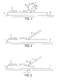
- FIG. 3 is an example of an ink separator of FIG. 1 .
- FIG. 4 is another example of an ink separator of FIG. 1 .
- FIG. 5 is another example of an ink separator of FIG. 1 .
- FIG. 6 is another example of an ink separator of FIG. 1 .
- ink can be removed from a substrate such that the substrate can be re-used. That is, the substrate can be reused, reducing the costs both in dollars and in terms of environmental impact of daily printing.
- a synthetic substrate can be used as a substrate for a printing process.
- An example of such synthetic substrate is paper based on polypropylene.
- synthetic substrates can have a greater durability, synthetic substrates can have a lower ink adhesion.
- Solid inks can be used in a printing process. Such solid inks can be used in high resolution applications, resulting in high quality images. However, solid inks can have poor adhesion to substrates. The undesirable low ink adhesion characteristics of synthetic substrates and solid inks can be combined to create a beneficial result. For example, the low adhesion allows the ink to be removed. In particular, as will be described below, the ink can be removed by a mechanical process. As a result, the synthetic substrate can be re-used.
- users and in particular, users in an office environment can print documents using solid inks on synthetic substrates.
- the documents can be used as desired.
- the user can place the document into a system for removing the ink, rather than placing the document in a recycling bin.
- the synthetic substrate can be re-used.
- a synthetic substrate has been described as being suitable, other substrates can be used.
- a suitable substrate would have a higher mechanical strength to allow for multiple re-use. However, this does not exclude a substrate having mechanical properties that limit the application to one re-use. Such applications can still reduce the impact through a reduced recycling load of one sheet per two uses.
- a suitable substrate can have a reduced adhesion to a particular ink. As a result, the ink can be more readily removed.
- Synthetic substrates, such as a polypropylene substrate include such characteristics.
- a substrate that is substantially impermeable to ink can be used. Accordingly, ink will not penetrate the surface of the substrate and therefore can have a reduced adhesion and will not impart a residual color to the substrate. As will be described in further detail below, such impermeability, synthetic substrates, or other materials that reduce the adhesion of the ink can allow for a purely mechanical removal technique.
- FIG. 1 is a block diagram of a system for removing ink from a substrate according to an embodiment.
- the system 10 includes an ink separator 16 and a substrate conveyor 14.
- the ink separator 16 is configured to separate the ink from the substrate 14.
- the ink separator 16 can separate the ink from the substrate 12 leaving the substrate substantially intact. That is, in an embodiment, the ink separator 16 can separate the ink without removing a portion of the substrate. As a result, the substrate 12 can be re-used.
- the substrate 12 can be a synthetic substrate such as a polypropylene substrate.
- the ink can be a solid ink that has a low adhesion to the polypropylene substrate. As a result of the low adhesion of the solid ink to the polypropylene substrate, the ink can be removed in the ink separator 16.
- the ink separator 16 can take a variety of forms.
- the ink separator 16 is configured to mechanically separate the ink from the substrate. That is, the ink separator 16 includes a structure that makes physical contact to the substrate 12 and/or the ink to separate the ink from the substrate 12.
- the ink separator 16 can include scrapers, blades, brushes, abrasive wheels, or the like.
- the ink separator 16 can include a scraper to remove substantially remove the ink from the substrate 12. However, some ink may still adhere to the substrate 12. Subsequent brushing or other removal mechanisms can be used to substantially remove the remainder of the ink.
- the ink separator 16 can be configured to only mechanically separate the ink from the substrate 12.
- only mechanically separating the ink includes using only physical contact. That is, chemicals, heat, light, or the like are not used to separate the ink from the substrate 12. This does not mean that such techniques outside of mechanical separation cannot be applied to the substrate 12 outside of the system 10.
- ink can be applied to a substrate using differing heat levels, coatings, or the like to reduce the adhesion of the ink to the substrate 12. Ink can still be separated from such substrates 12 by only mechanical separating in the system 10.
- the substrate conveyor 14 is configured to provide the substrate 12 to the ink separator 16.
- the substrate conveyor 14 can be any variety of substrate transport mechanisms.
- the substrate conveyor 14 can include rollers, belts, air jets, wheels, or the like.
- the substrate conveyor 14 can provide the substrate 12 to the ink separator 16 in a variety of ways.
- the substrate conveyor 14 can provide tension to the substrate 12 such that the substrate 12 contacts the ink separator 16.
- pressure can be applied by a roller to hold the substrate 12 to the ink separator 16. Regardless of how the substrate 12 is provided to the ink separator 16 the substrate conveyor 14 can then transport the substrate 12 to the user, collate the substrate 12, or otherwise prepare the substrate for subsequent collection and re-use.
- the system 10 includes a scanner 18.
- the scanner 18 is disposed after an exit of the ink separator 16 and configured to analyze ink remaining on the substrate 20, illustrated in phantom.
- the ink separator 16 has been described as substantially removing the ink from the substrate 12, some ink can remain. For example, the ink may have a higher adhesion to the substrate 12, the ink separator 16 may need maintenance, or the like.
- the scanner 18 can be configured to monitor the substrate 20 to analyze any remaining ink.
- the substrate 20 can be directed towards the ink separator 16 again for a subsequent removal of ink.
- the substrate conveyor 14 can be configured to route the substrate 20 to the entrance of the ink separator 16, reverse the direction of the substrate 20 back through the ink separator 16, or the like.
- Such ink separation and scanning can be repeatedly performed to achieve a desired level of ink removal. If a desired level of ink removal cannot be obtained, the scanner can cause the sheet to be rejected.
- the system 10 can take a variety of forms.
- the system 10 can be a stand alone system similar to a paper shredder.
- a slot can receive the substrate with the ink.
- An internal ink separator 16 removes the ink and a collection bin stores the processed substrates 12.
- the system 10 can be part of a printing system.
- the printing system can direct particular substrates 12 towards an ink separator 16. Once the ink is separated from the substrate 12, the substrate 12 can be routed towards a tray accessible by the printing system for subsequent printing.
- the lifetime environmental costs of printing and in particular, office printing are reduced.
- the energy, emissions, chemicals, and the like associated with recycling and or creation of virgin substrates can be reduced and/or eliminated. That is, with the system 10, the substrate 12 can be processed on site to remove the ink and prepared for subsequent printing.
- a paper recycling-based approach would include transportation to a paper making facility, repulping, ink removal, processing into paper, and transportation back to the office. Such processing and transportation can be eliminated.
- FIG. 2 is a block diagram of a system for removing ink from a substrate according to another embodiment.
- the system 30 includes an ink collector 32 configured to collect the ink removed from the substrate.
- the ink collector 32 can include brushes, vacuums, air jets, or the like to direct the detached ink to a collection receptacle.
- the ink separator 16 may not completely separate the ink from the substrate 12. That is, the ink collector 32 can be configured to perform some separation of the ink from the substrate 12. In other words, the separation and collection of ink can be a combined and/or form a continuous process between the ink separator 16 and the ink collector 32.
- a blade may partially remove the ink from the substrate 12. Some ink may remain that is attached to the substrate 12 yet loosened by the ink separator 16. The brushes and vacuum of the ink collector 32 can substantially remove the remaining ink and directed it towards an ink receptacle 33.
- a solvent can be used in the processing of the substrate 12.
- a solvent applicator 34 is configured to apply solvent 35 to the substrate 12. The solvent can reduce the adherence of the ink to the substrate 12, suspend the ink for easier collection, or the like. Accordingly, the ink can be removed more easily from the substrate 12. It should be noted that although in an embodiment has been described above with only mechanical separation and no solvents, chemicals, or the like, other embodiments can include such additions.
- the solvent applicator 34 has been illustrated as applying a solvent 35 to the substrate 12 prior to entry into the ink separator 16, the solvent applicator 34 can be disposed in other locations.
- the solvent applicator 34 can be internal to the ink separator 16 and configured to apply the solvent 35 to a blade, scraper, or the like.
- FIG. 3 is an example of an ink separator of FIG. 1 .
- the ink separator 16 includes a blade 42.
- the blade 42 can include a single fixed blade.
- the blade 42 includes multiple individual teeth 44.
- the blade 42 can be a rotating blade configured to rotate in direction 43.
- the teeth 44 can be disposed along the blade 42 in a helical pattern.
- the blade 42 can be disposed relative to the substrate conveyor 14 such that the blade 42 can separate the ink from the substrate 12.
- the substrate conveyor 14 can position the substrate 14 such that the blade 42 contacts the substrate. As a result, the blade 42 can remove the ink 40 down to the substrate 12.
- the blade 42 need not contact the substrate 12.
- a solid ink can have poor adhesion to a synthetic substrate. Accordingly, the blade 42 can be disposed to contact the ink 40, yet due to the reduced adhesion of the ink 40 to the substrate 12 and the internal cohesiveness of the ink 40, the ink 40 can be pulled off of the substrate 12.
- the blade 42 can rotate in a direction opposite to direction 43.
- the teeth 44 can extend longitudinally along the blade 42.
- the hardness of the blade 42 can be selected based on the hardness of the substrate 12.
- the blade material can be selected to have a hardness that is greater than that of the substrate 12.
- the blade can have a hardness that is greater than the ink on the substrate 12.
- the ink 40 can deform and separate from the substrate 12 while the blade 42 remains substantially intact.
- the hardness of the blade 42 has been described as an example relative to the ink 40 and the substrate 12, such relative hardness is not limited to blades. Any structure that can contact the ink 40 and the substrate 12 during the removal of the ink can have such hardness characteristics.
- bristles of brushes used in removal of the ink can be formed of a material with such a hardness.
- FIG. 4 is another example of an ink separator of FIG. 1 .
- a blade 50 of the ink separator 16 is disposed such that the substrate conveyor 14 can bring the substrate 12 in contact with the blade. As the substrate 12 is moved by the substrate conveyor 14, the blade 50 contacts the ink 40 and separates it from the substrate 12.
- FIG. 5 is another example of an ink separator of FIG. 1 .
- a blade 50 can be used to separate the ink 40 from the substrate 12.
- the blade 50 can be disposed in the ink separator 16 such that is removes a potion of the substrate 12.
- a pressure controller can control the pressure between the blade 50 and the substrate conveyor 14.
- roller 72 can be configured to apply pressure to the substrate 12.
- the pressure controller can take a variety of forms.
- the pressure controller can include pressure sensors, actuators, feedback controllers, or the like that regulates the pressure of the blade 50.
- the pressure controller can include a spring loaded mechanism that applies a particular pressure, without such feedback or monitoring.
- solid inks may have a lower adhesion to a synthetic substrate and can be removed.
- the substrate 12 may be marked with other inks or materials that have higher adhesion to the substrate.
- a user may make notes on the substrate 12 with a pen.
- Such ink may adhere to the substrate 12 more than wax based inks.
- Mechanical techniques, such as the blades, brushes, and the like described above may not remove the ink from the pen. Accordingly, while separating the ink from the substrate, the blade 50 can also remove a portion of the substrate 12. Although this can limit the lifetime of the substrate 12, inks, marks, foreign objects, or the like that would otherwise remain on the substrate 12 can be removed, preparing the substrate for re-use.
- FIG. 6 is another example of an ink separator of FIG. 1 .
- the ink separator of FIG. 6 includes an ultrasonic cleaner 61.
- the substrate conveyor 14 is configured to transport the substrate 12 into a vessel 63 containing a fluid 60. At least a part of the substrate 12 is submerged in the fluid 60, although in FIG. 6 , the entire substrate 12 is illustrated as being submerged.
- the ultrasonic cleaner 61 includes an ultrasonic source 62.
- the ultrasonic source 62 is configured to emit ultrasonic vibrations 64 which propagate through the fluid 60.
- the ultrasonic vibrations 64 detach the ink 40 from the substrate 12 and suspend it in the fluid 60 as particles 66.
- the substrate 12 can then be removed from the ultrasonic cleaner 61, leaving the particles 66 behind.
- an ink separator 16 for removing ink from a substrate, such techniques, structures, and the like can be combined together.
- the ultrasonic cleaner 61 can be combined with a rotating blade 42. Any combination of such techniques and structures is possible.
Landscapes
- Engineering & Computer Science (AREA)
- Life Sciences & Earth Sciences (AREA)
- Mechanical Engineering (AREA)
- Wood Science & Technology (AREA)
- Forests & Forestry (AREA)
- Cleaning In Electrography (AREA)
- Coating Apparatus (AREA)
- Ink Jet (AREA)
- Physical Or Chemical Processes And Apparatus (AREA)
- Application Of Or Painting With Fluid Materials (AREA)
- Accessory Devices And Overall Control Thereof (AREA)
- Paints Or Removers (AREA)
Abstract
A system for removing ink from a substrate. The system includes an ink separator (16) configured to separate the ink from the substrate; and a substrate conveyor (14) configured to provide the substrate to the ink separator. Accordingly, the ink can be removed from the substrate such that the substrate can be re-used.
Description
- This disclosure relates to substrate re-use and, in particular to systems and methods of solid ink removal for substrate re-use.
- Paper represents a very large portion of the lifecycle environmental cost of printing. Both the actual manufacture of the paper, whether formed from recycled material or virgin pulp, as well as the shipping costs are high in terms of impact to the environment. Many office documents are printed multiple times in their lifetimes and often are recycled on the day they are printed. As a result, many office documents incur an increased environmental impact over their lifetime.
- Ink, toner, or the like can be removed from paper. However, conventional ink removing techniques include re-pulping of the paper. That is, the paper is shredded, disintegrated, or otherwise returned to a slurry. Agglomeration agents, densifying agents, or the like are added to cause the ink suspended in the slurry to agglomerate such that it can be removed by screening, filtering, washing, sedimentation, or the like. Once the ink is removed, the remaining slurry must reenter the papermaking process before it can be re-used. This process is typically done at a location remote to the use location and therefore this cycle incurs round trip transportation costs as well.
- An embodiment includes a system for removing ink from a substrate including an ink separator configured to separate the ink from the substrate; and a substrate conveyor configured to provide the substrate to the ink separator.
- Another embodiment includes a method of removing solid ink from a substrate including receiving the substrate with the solid ink; mechanically separating the solid ink from the substrate; and returning the substrate.
- Another embodiment includes a printing system including a coating source configured to apply a coating to a substrate; and a marking engine configured to apply ink over the coating such that the coating is disposed between the ink and the substrate.
-
FIG. 1 is a block diagram of a system for removing ink from a substrate according to an embodiment. -
FIG. 2 is a block diagram of a system for removing ink from a substrate according to another embodiment. -
FIG. 3 is an example of an ink separator ofFIG. 1 . -
FIG. 4 is another example of an ink separator ofFIG. 1 . -
FIG. 5 is another example of an ink separator ofFIG. 1 . -
FIG. 6 is another example of an ink separator ofFIG. 1 . - Embodiments will be described in reference to the drawings. In particular, embodiments will be described where ink can be removed from a substrate such that the substrate can be re-used. That is, the substrate can be reused, reducing the costs both in dollars and in terms of environmental impact of daily printing.
- In an embodiment, a synthetic substrate can be used as a substrate for a printing process. An example of such synthetic substrate is paper based on polypropylene. Although synthetic substrates can have a greater durability, synthetic substrates can have a lower ink adhesion.
- Solid inks can be used in a printing process. Such solid inks can be used in high resolution applications, resulting in high quality images. However, solid inks can have poor adhesion to substrates. The undesirable low ink adhesion characteristics of synthetic substrates and solid inks can be combined to create a beneficial result. For example, the low adhesion allows the ink to be removed. In particular, as will be described below, the ink can be removed by a mechanical process. As a result, the synthetic substrate can be re-used.
- Accordingly, users and in particular, users in an office environment, can print documents using solid inks on synthetic substrates. The documents can be used as desired. When finished, the user can place the document into a system for removing the ink, rather than placing the document in a recycling bin. As a result, after ink removal, the synthetic substrate can be re-used. The various costs, as described above, associated with the transportation and recycling of paper can be reduced if not eliminated.
- Although a synthetic substrate has been described as being suitable, other substrates can be used. For example, a suitable substrate would have a higher mechanical strength to allow for multiple re-use. However, this does not exclude a substrate having mechanical properties that limit the application to one re-use. Such applications can still reduce the impact through a reduced recycling load of one sheet per two uses. In another example, a suitable substrate can have a reduced adhesion to a particular ink. As a result, the ink can be more readily removed. Synthetic substrates, such as a polypropylene substrate include such characteristics.
- In another example, a substrate that is substantially impermeable to ink can be used. Accordingly, ink will not penetrate the surface of the substrate and therefore can have a reduced adhesion and will not impart a residual color to the substrate. As will be described in further detail below, such impermeability, synthetic substrates, or other materials that reduce the adhesion of the ink can allow for a purely mechanical removal technique.
-
FIG. 1 is a block diagram of a system for removing ink from a substrate according to an embodiment. Thesystem 10 includes anink separator 16 and asubstrate conveyor 14. Theink separator 16 is configured to separate the ink from thesubstrate 14. In an embodiment, theink separator 16 can separate the ink from thesubstrate 12 leaving the substrate substantially intact. That is, in an embodiment, theink separator 16 can separate the ink without removing a portion of the substrate. As a result, thesubstrate 12 can be re-used. - As described above, the
substrate 12 can be a synthetic substrate such as a polypropylene substrate. The ink can be a solid ink that has a low adhesion to the polypropylene substrate. As a result of the low adhesion of the solid ink to the polypropylene substrate, the ink can be removed in theink separator 16. - The
ink separator 16 can take a variety of forms. In an embodiment, theink separator 16 is configured to mechanically separate the ink from the substrate. That is, theink separator 16 includes a structure that makes physical contact to thesubstrate 12 and/or the ink to separate the ink from thesubstrate 12. For example, theink separator 16 can include scrapers, blades, brushes, abrasive wheels, or the like. - In an embodiment, the
ink separator 16 can include a scraper to remove substantially remove the ink from thesubstrate 12. However, some ink may still adhere to thesubstrate 12. Subsequent brushing or other removal mechanisms can be used to substantially remove the remainder of the ink. - In an embodiment, the
ink separator 16 can be configured to only mechanically separate the ink from thesubstrate 12. As used herein, only mechanically separating the ink includes using only physical contact. That is, chemicals, heat, light, or the like are not used to separate the ink from thesubstrate 12. This does not mean that such techniques outside of mechanical separation cannot be applied to thesubstrate 12 outside of thesystem 10. For example, as will be described below, ink can be applied to a substrate using differing heat levels, coatings, or the like to reduce the adhesion of the ink to thesubstrate 12. Ink can still be separated fromsuch substrates 12 by only mechanical separating in thesystem 10. - The
substrate conveyor 14 is configured to provide thesubstrate 12 to theink separator 16. Thesubstrate conveyor 14 can be any variety of substrate transport mechanisms. For example, thesubstrate conveyor 14 can include rollers, belts, air jets, wheels, or the like. Thesubstrate conveyor 14 can provide thesubstrate 12 to theink separator 16 in a variety of ways. For example, thesubstrate conveyor 14 can provide tension to thesubstrate 12 such that thesubstrate 12 contacts theink separator 16. In another embodiment, pressure can be applied by a roller to hold thesubstrate 12 to theink separator 16. Regardless of how thesubstrate 12 is provided to theink separator 16 thesubstrate conveyor 14 can then transport thesubstrate 12 to the user, collate thesubstrate 12, or otherwise prepare the substrate for subsequent collection and re-use. - In an embodiment, the
system 10 includes ascanner 18. Thescanner 18 is disposed after an exit of theink separator 16 and configured to analyze ink remaining on thesubstrate 20, illustrated in phantom. Although theink separator 16 has been described as substantially removing the ink from thesubstrate 12, some ink can remain. For example, the ink may have a higher adhesion to thesubstrate 12, theink separator 16 may need maintenance, or the like. Regardless, thescanner 18 can be configured to monitor thesubstrate 20 to analyze any remaining ink. - Accordingly, if ink has not been sufficiently removed from the
substrate 20, thesubstrate 20 can be directed towards theink separator 16 again for a subsequent removal of ink. For example, thesubstrate conveyor 14 can be configured to route thesubstrate 20 to the entrance of theink separator 16, reverse the direction of thesubstrate 20 back through theink separator 16, or the like. Such ink separation and scanning can be repeatedly performed to achieve a desired level of ink removal. If a desired level of ink removal cannot be obtained, the scanner can cause the sheet to be rejected. - The
system 10 can take a variety of forms. For example, thesystem 10 can be a stand alone system similar to a paper shredder. A slot can receive the substrate with the ink. Aninternal ink separator 16 removes the ink and a collection bin stores the processedsubstrates 12. In another example, thesystem 10 can be part of a printing system. For example, the printing system can directparticular substrates 12 towards anink separator 16. Once the ink is separated from thesubstrate 12, thesubstrate 12 can be routed towards a tray accessible by the printing system for subsequent printing. - As a result, the lifetime environmental costs of printing and in particular, office printing are reduced. The energy, emissions, chemicals, and the like associated with recycling and or creation of virgin substrates can be reduced and/or eliminated. That is, with the
system 10, thesubstrate 12 can be processed on site to remove the ink and prepared for subsequent printing. In contrast, a paper recycling-based approach would include transportation to a paper making facility, repulping, ink removal, processing into paper, and transportation back to the office. Such processing and transportation can be eliminated. -
FIG. 2 is a block diagram of a system for removing ink from a substrate according to another embodiment. In this embodiment, thesystem 30 includes anink collector 32 configured to collect the ink removed from the substrate. For example, theink collector 32 can include brushes, vacuums, air jets, or the like to direct the detached ink to a collection receptacle. - In an embodiment, the
ink separator 16 may not completely separate the ink from thesubstrate 12. That is, theink collector 32 can be configured to perform some separation of the ink from thesubstrate 12. In other words, the separation and collection of ink can be a combined and/or form a continuous process between theink separator 16 and theink collector 32. For example, as will be described in further detail below, a blade may partially remove the ink from thesubstrate 12. Some ink may remain that is attached to thesubstrate 12 yet loosened by theink separator 16. The brushes and vacuum of theink collector 32 can substantially remove the remaining ink and directed it towards anink receptacle 33. - In another embodiment, a solvent can be used in the processing of the
substrate 12. In this example, asolvent applicator 34 is configured to apply solvent 35 to thesubstrate 12. The solvent can reduce the adherence of the ink to thesubstrate 12, suspend the ink for easier collection, or the like. Accordingly, the ink can be removed more easily from thesubstrate 12. It should be noted that although in an embodiment has been described above with only mechanical separation and no solvents, chemicals, or the like, other embodiments can include such additions. - Furthermore, although the
solvent applicator 34 has been illustrated as applying a solvent 35 to thesubstrate 12 prior to entry into theink separator 16, thesolvent applicator 34 can be disposed in other locations. For example, thesolvent applicator 34 can be internal to theink separator 16 and configured to apply the solvent 35 to a blade, scraper, or the like. -
FIG. 3 is an example of an ink separator ofFIG. 1 . In this embodiment, theink separator 16 includes ablade 42. As will be described in further detail below, theblade 42 can include a single fixed blade. In this embodiment, theblade 42 includes multipleindividual teeth 44. Theblade 42 can be a rotating blade configured to rotate in direction 43. Theteeth 44 can be disposed along theblade 42 in a helical pattern. - The
blade 42 can be disposed relative to thesubstrate conveyor 14 such that theblade 42 can separate the ink from thesubstrate 12. In an embodiment, thesubstrate conveyor 14 can position thesubstrate 14 such that theblade 42 contacts the substrate. As a result, theblade 42 can remove theink 40 down to thesubstrate 12. - However, in another embodiment, the
blade 42 need not contact thesubstrate 12. For example, as described above, a solid ink can have poor adhesion to a synthetic substrate. Accordingly, theblade 42 can be disposed to contact theink 40, yet due to the reduced adhesion of theink 40 to thesubstrate 12 and the internal cohesiveness of theink 40, theink 40 can be pulled off of thesubstrate 12. - Although particular tooth pattern and direction of rotation have been described, other tooth patterns and rotation directions can be used. For example, the
blade 42 can rotate in a direction opposite to direction 43. In another example, theteeth 44 can extend longitudinally along theblade 42. - In an embodiment, the hardness of the
blade 42 can be selected based on the hardness of thesubstrate 12. For example, the blade material can be selected to have a hardness that is greater than that of thesubstrate 12. As a result, if theblade 42 contacts thesubstrate 12, the contact will have a reduced effect on thesubstrate 12. In addition, the blade can have a hardness that is greater than the ink on thesubstrate 12. As a result, theink 40 can deform and separate from thesubstrate 12 while theblade 42 remains substantially intact. - Although the hardness of the
blade 42 has been described as an example relative to theink 40 and thesubstrate 12, such relative hardness is not limited to blades. Any structure that can contact theink 40 and thesubstrate 12 during the removal of the ink can have such hardness characteristics. For example, bristles of brushes used in removal of the ink can be formed of a material with such a hardness. -
FIG. 4 is another example of an ink separator ofFIG. 1 . In this embodiment, ablade 50 of theink separator 16 is disposed such that thesubstrate conveyor 14 can bring thesubstrate 12 in contact with the blade. As thesubstrate 12 is moved by thesubstrate conveyor 14, theblade 50 contacts theink 40 and separates it from thesubstrate 12. -
FIG. 5 is another example of an ink separator ofFIG. 1 . As described above, ablade 50 can be used to separate theink 40 from thesubstrate 12. However, theblade 50 can be disposed in theink separator 16 such that is removes a potion of thesubstrate 12. For example, as thesubstrate 12 passes the blade aportion 70 is cut away. In an embodiment, a pressure controller can control the pressure between theblade 50 and thesubstrate conveyor 14. For example,roller 72 can be configured to apply pressure to thesubstrate 12. - The pressure controller can take a variety of forms. For example, the pressure controller can include pressure sensors, actuators, feedback controllers, or the like that regulates the pressure of the
blade 50. In another embodiment, the pressure controller can include a spring loaded mechanism that applies a particular pressure, without such feedback or monitoring. - As described above, solid inks may have a lower adhesion to a synthetic substrate and can be removed. However, the
substrate 12 may be marked with other inks or materials that have higher adhesion to the substrate. For example, a user may make notes on thesubstrate 12 with a pen. Such ink may adhere to thesubstrate 12 more than wax based inks. Mechanical techniques, such as the blades, brushes, and the like described above may not remove the ink from the pen. Accordingly, while separating the ink from the substrate, theblade 50 can also remove a portion of thesubstrate 12. Although this can limit the lifetime of thesubstrate 12, inks, marks, foreign objects, or the like that would otherwise remain on thesubstrate 12 can be removed, preparing the substrate for re-use. -
FIG. 6 is another example of an ink separator ofFIG. 1 . The ink separator ofFIG. 6 includes anultrasonic cleaner 61. Thesubstrate conveyor 14 is configured to transport thesubstrate 12 into avessel 63 containing a fluid 60. At least a part of thesubstrate 12 is submerged in the fluid 60, although inFIG. 6 , theentire substrate 12 is illustrated as being submerged. - The
ultrasonic cleaner 61 includes anultrasonic source 62. Theultrasonic source 62 is configured to emitultrasonic vibrations 64 which propagate through the fluid 60. Theultrasonic vibrations 64 detach theink 40 from thesubstrate 12 and suspend it in the fluid 60 asparticles 66. Thesubstrate 12 can then be removed from theultrasonic cleaner 61, leaving theparticles 66 behind. - Although particular techniques and structures of an
ink separator 16 have been described for removing ink from a substrate, such techniques, structures, and the like can be combined together. For example, theultrasonic cleaner 61 can be combined with arotating blade 42. Any combination of such techniques and structures is possible.
Claims (14)
- A system for removing ink from a substrate, comprising:an ink separator configured to separate the ink from the substrate; anda substrate conveyor configured to provide the substrate to the ink separator.
- The system of claim 1, wherein the ink separator is configured to mechanically separate the ink from the substrate.
- The system of claim 1 or claim 2, wherein the ink separator comprises a blade, such as a rotating blade, for example disposed in the ink separator to remove a portion of the substrate.
- The system of claim 1 or claim 2, wherein the ink separator comprises an ultrasonic cleaner.
- The system of any of the preceding claims, further comprising an ink collector configured to collect the ink removed from the substrate, the ink collector preferably comprising a brush and a vacuum, or a blade and a vacuum.
- The system of any of the preceding claims, further comprising a scanner disposed after an exit of the ink separator and configured to analyze ink remaining on the substrate.
- A method of removing solid ink from a substrate, comprising:receiving the substrate with the solid ink;mechanically separating the solid ink from the substrate; andreturning the substrate.
- The method of claim 7, further comprising scraping the solid ink from a surface of the substrate.
- The method of claim 7 or claim 8, further comprising removing a portion of the substrate while separating the solid ink from the substrate.
- The method of claim 7, further comprising:submerging at least a part of the substrate in a fluid; andultrasonically agitating the fluid.
- A method according to any of claims 7 to 10, wherein the ink is separated using a blade.
- The method of claim 11, wherein:the blade has a first hardness;the substrate has a second hardness; andthe first hardness is less than the second hardness.
- The system of claim 12, wherein:the ink has a third hardness; andthe first hardness is greater than the third hardness.
- A method according to any of claims 7 to 13, wherein the substrate is a synthetic substrate, such as a polymer.
Applications Claiming Priority (1)
| Application Number | Priority Date | Filing Date | Title |
|---|---|---|---|
| US12/403,626 US8185996B2 (en) | 2009-03-13 | 2009-03-13 | System and method of solid ink removal for substrate re-use |
Publications (1)
| Publication Number | Publication Date |
|---|---|
| EP2230045A1 true EP2230045A1 (en) | 2010-09-22 |
Family
ID=42537667
Family Applications (1)
| Application Number | Title | Priority Date | Filing Date |
|---|---|---|---|
| EP20100156117 Withdrawn EP2230045A1 (en) | 2009-03-13 | 2010-03-10 | System and Method of Solid Ink Removal for Substrate Re-Use |
Country Status (6)
| Country | Link |
|---|---|
| US (2) | US8185996B2 (en) |
| EP (1) | EP2230045A1 (en) |
| JP (1) | JP6095254B2 (en) |
| KR (1) | KR101605208B1 (en) |
| CN (1) | CN101837352B (en) |
| TW (1) | TW201040031A (en) |
Cited By (2)
| Publication number | Priority date | Publication date | Assignee | Title |
|---|---|---|---|---|
| EP3396060A1 (en) * | 2017-04-24 | 2018-10-31 | Seiko Epson Corporation | Processing device, sheet manufacturing apparatus, processing method, and sheet manufacturing method |
| EP3396062A3 (en) * | 2017-04-24 | 2019-01-02 | Seiko Epson Corporation | Processing device, sheet manufacturing apparatus, processing method, and manufacturing method of sheet |
Families Citing this family (4)
| Publication number | Priority date | Publication date | Assignee | Title |
|---|---|---|---|---|
| US8810855B1 (en) | 2013-01-30 | 2014-08-19 | Hewlett-Packard Development Company, L.P. | Erasable printouts including erasable features |
| CN104438153A (en) * | 2014-12-02 | 2015-03-25 | 赵永兴 | Physical printing ink removal machine |
| WO2018002943A1 (en) | 2016-06-30 | 2018-01-04 | Hewlett-Packard Development Company, L.P. | Processing print media |
| CN118893509B (en) * | 2024-06-19 | 2025-09-23 | 贵溪奥泰铜业有限公司 | Copper plate coating equipment |
Citations (9)
| Publication number | Priority date | Publication date | Assignee | Title |
|---|---|---|---|---|
| US3762101A (en) * | 1972-08-09 | 1973-10-02 | Armstrong Cork Co | Brush-out apparatus |
| US4440635A (en) | 1979-03-29 | 1984-04-03 | Haigh M. Reiniger | Process and apparatus for the recovery of cellulose fibers from paper-plastic mixtures |
| EP0336059A1 (en) * | 1988-03-25 | 1989-10-11 | Nippon CMK Corp. | A method of surface grinding of planar member |
| US5238538A (en) | 1991-11-25 | 1993-08-24 | Georgia Tech Research Corporation | Method for deinking recycled fiber by applying direct current electric field |
| US5306349A (en) * | 1992-11-23 | 1994-04-26 | Sony Music Entertainment, Inc. | Method for removing coatings from compact discs |
| WO1996027045A1 (en) * | 1995-02-21 | 1996-09-06 | Watson Dana L | System and method for recycling materials |
| US5997388A (en) * | 1997-08-11 | 1999-12-07 | Micron Electronics, Inc. | Apparatus for removing marks from integrated circuit devices |
| JP2000190197A (en) * | 1998-12-25 | 2000-07-11 | Nippon Coated Abureeshibu Kk | Printed circuit board polishing method |
| US20060016731A1 (en) | 2004-07-21 | 2006-01-26 | Giancarlo Dal Maso | Reactor particularly suitable for cleaning fibrous suspensions dispersed in liquids |
Family Cites Families (17)
| Publication number | Priority date | Publication date | Assignee | Title |
|---|---|---|---|---|
| FR2430304A1 (en) * | 1978-07-05 | 1980-02-01 | Saint Gobain | CLEANING PLASTIC SHEETS |
| US4382308A (en) * | 1981-02-18 | 1983-05-10 | Chemcut Corporation | Scrubbing torque monitoring and control system |
| US4993097A (en) * | 1989-07-31 | 1991-02-19 | D.E.M. Controls Of Canada | Circuit board deburring system |
| FR2664627B1 (en) * | 1990-07-12 | 1995-11-24 | Tech Ind Papiers C Centre | PROCESS FOR INKING PRINTED PAPERS. |
| JP2745856B2 (en) * | 1991-03-28 | 1998-04-28 | 船井電機株式会社 | Copy paper recycling device |
| US5876559A (en) * | 1991-06-25 | 1999-03-02 | International Paper Company | Deinking of impact and non-impact printed paper by an agglomeration process |
| JPH07121067A (en) * | 1993-08-11 | 1995-05-12 | Ricoh Co Ltd | Image forming substance removing device from image carrier and image carrier processing device provided with destabilizing liquid applying means having processing head |
| JPH07175254A (en) * | 1993-12-17 | 1995-07-14 | Ricoh Co Ltd | Regenerating method of image holding support |
| JPH07239595A (en) * | 1994-02-28 | 1995-09-12 | Ricoh Co Ltd | Image carrier post-processing device |
| US6245195B1 (en) * | 1996-03-19 | 2001-06-12 | Westvaco Corporation | Decontamination of waste papers |
| US6250224B1 (en) * | 1997-10-27 | 2001-06-26 | Hans J. Hofmann | Powder sprayer |
| FI20000532A0 (en) * | 2000-03-08 | 2000-03-08 | Process Team Finland Oy | Method and apparatus for treating a moving surface |
| JP3859964B2 (en) * | 2000-12-05 | 2006-12-20 | 理想科学工業株式会社 | Printing method, printing sheet reproduction method and printing sheet |
| US20020083963A1 (en) * | 2000-12-28 | 2002-07-04 | Proulx Rodney B. | Multi-blade, rotary blade cleaner |
| JP4066010B2 (en) | 2002-06-28 | 2008-03-26 | テクノロール株式会社 | Over-emulsifying / over-printing ink removal device |
| JP2008143180A (en) | 2006-12-07 | 2008-06-26 | Heidelberger Druckmas Ag | Printing machine equipped with washing unit for inking unit |
| US20080229953A1 (en) * | 2007-03-20 | 2008-09-25 | Komori Corporation | Cleaning apparatus |
-
2009
- 2009-03-13 US US12/403,626 patent/US8185996B2/en not_active Expired - Fee Related
-
2010
- 2010-03-10 KR KR1020100021175A patent/KR101605208B1/en not_active Expired - Fee Related
- 2010-03-10 EP EP20100156117 patent/EP2230045A1/en not_active Withdrawn
- 2010-03-10 TW TW99106951A patent/TW201040031A/en unknown
- 2010-03-11 JP JP2010054522A patent/JP6095254B2/en not_active Expired - Fee Related
- 2010-03-15 CN CN201010150744.3A patent/CN101837352B/en not_active Expired - Fee Related
-
2012
- 2012-04-25 US US13/456,062 patent/US20120206546A1/en not_active Abandoned
Patent Citations (9)
| Publication number | Priority date | Publication date | Assignee | Title |
|---|---|---|---|---|
| US3762101A (en) * | 1972-08-09 | 1973-10-02 | Armstrong Cork Co | Brush-out apparatus |
| US4440635A (en) | 1979-03-29 | 1984-04-03 | Haigh M. Reiniger | Process and apparatus for the recovery of cellulose fibers from paper-plastic mixtures |
| EP0336059A1 (en) * | 1988-03-25 | 1989-10-11 | Nippon CMK Corp. | A method of surface grinding of planar member |
| US5238538A (en) | 1991-11-25 | 1993-08-24 | Georgia Tech Research Corporation | Method for deinking recycled fiber by applying direct current electric field |
| US5306349A (en) * | 1992-11-23 | 1994-04-26 | Sony Music Entertainment, Inc. | Method for removing coatings from compact discs |
| WO1996027045A1 (en) * | 1995-02-21 | 1996-09-06 | Watson Dana L | System and method for recycling materials |
| US5997388A (en) * | 1997-08-11 | 1999-12-07 | Micron Electronics, Inc. | Apparatus for removing marks from integrated circuit devices |
| JP2000190197A (en) * | 1998-12-25 | 2000-07-11 | Nippon Coated Abureeshibu Kk | Printed circuit board polishing method |
| US20060016731A1 (en) | 2004-07-21 | 2006-01-26 | Giancarlo Dal Maso | Reactor particularly suitable for cleaning fibrous suspensions dispersed in liquids |
Cited By (5)
| Publication number | Priority date | Publication date | Assignee | Title |
|---|---|---|---|---|
| EP3396060A1 (en) * | 2017-04-24 | 2018-10-31 | Seiko Epson Corporation | Processing device, sheet manufacturing apparatus, processing method, and sheet manufacturing method |
| EP3396062A3 (en) * | 2017-04-24 | 2019-01-02 | Seiko Epson Corporation | Processing device, sheet manufacturing apparatus, processing method, and manufacturing method of sheet |
| TWI665533B (en) * | 2017-04-24 | 2019-07-11 | 日商精工愛普生股份有限公司 | Processing device, sheet manufacturing apparatus, processing method, and sheet manufacturing method |
| EP3524729A1 (en) * | 2017-04-24 | 2019-08-14 | Seiko Epson Corporation | Processing device, sheet manufacturing apparatus, processing method, and manufacturing method of sheet |
| US10781554B2 (en) | 2017-04-24 | 2020-09-22 | Seiko Epson Corporation | Processing device, sheet manufacturing apparatus, processing method, and sheet manufacturing method |
Also Published As
| Publication number | Publication date |
|---|---|
| US20120206546A1 (en) | 2012-08-16 |
| JP2010214368A (en) | 2010-09-30 |
| KR20100103385A (en) | 2010-09-27 |
| JP6095254B2 (en) | 2017-03-15 |
| CN101837352B (en) | 2014-10-29 |
| US20100229889A1 (en) | 2010-09-16 |
| US8185996B2 (en) | 2012-05-29 |
| TW201040031A (en) | 2010-11-16 |
| CN101837352A (en) | 2010-09-22 |
| KR101605208B1 (en) | 2016-03-21 |
Similar Documents
| Publication | Publication Date | Title |
|---|---|---|
| US20120206546A1 (en) | System and method of solid ink removal for substrate re-use | |
| CN102381019B (en) | Method for detection of occurrence of printing errors on printed substrates during processing thereof on a printing press | |
| KR101794262B1 (en) | Reusable printing medium and apparatus employing the same | |
| WO2009073145A1 (en) | Method and apparatus for measuring deposition of particulate contaminants in pulp and paper slurries | |
| JP2004501293A (en) | Control method of organic contaminants in fiber | |
| CN113201956B (en) | Fiber treatment system and fiber treatment method | |
| JP4984060B2 (en) | Paper quality control method and method for producing slip sheet for storage and / or transport slip of glass substrate for flat panel display | |
| Counsell et al. | Desktop paper recycling: A survey of novel technologies that might recycle office paper within the office | |
| CN100349752C (en) | Image decolorizing apparatus | |
| EP3169526B1 (en) | Flat support printing machine equipped with a coating unit for applying a coating substance | |
| US11492759B2 (en) | Fiber body forming method and sheet | |
| US20130220003A1 (en) | Method and apparatus for measuring deposition of particulate contaminants in pulp and paper slurries | |
| US20190240873A1 (en) | Method and apparatus for embossing a substrate | |
| KR102466319B1 (en) | Tissue manufacturing system using old corrugated container and used paper and tissue manufacturing method using the same | |
| EP3524729A1 (en) | Processing device, sheet manufacturing apparatus, processing method, and manufacturing method of sheet | |
| JP4343133B2 (en) | Image erasing device | |
| Counsell et al. | Un-printing toner: early results | |
| JP2018184668A (en) | Processing apparatus, sheet manufacturing apparatus, processing method, and sheet manufacturing method | |
| Ramasubramanian et al. | Characterization of focused high frequency ultrasonic removal of thermally fused toner from paper surfaces-an experimental study | |
| CN101316709A (en) | Method for detecting the occurrence of printing errors on a printing substrate during the processing of a printing press | |
| Fischer | Investigations of Deinkability and Ink-Paper Interactions | |
| JP2008155393A (en) | Blanket cylinder dust remover | |
| DE102011056965A1 (en) | Device for cleaning e.g. toner elements, on outer surface of roller in electrographic printing device to print paper web, has fan mechanism creating airflow such that airflow presses edge against surface and cleans particles on surface | |
| Azmi et al. | Brightness Evaluation on Laser-Printed Paper Deinking Quality Facilitate By Lipase and Esterase Enzymes | |
| JPH10288930A (en) | Reproduction device for recording material |
Legal Events
| Date | Code | Title | Description |
|---|---|---|---|
| PUAI | Public reference made under article 153(3) epc to a published international application that has entered the european phase |
Free format text: ORIGINAL CODE: 0009012 |
|
| AK | Designated contracting states |
Kind code of ref document: A1 Designated state(s): AT BE BG CH CY CZ DE DK EE ES FI FR GB GR HR HU IE IS IT LI LT LU LV MC MK MT NL NO PL PT RO SE SI SK SM TR |
|
| AX | Request for extension of the european patent |
Extension state: AL BA ME RS |
|
| 17P | Request for examination filed |
Effective date: 20110322 |
|
| 17Q | First examination report despatched |
Effective date: 20160301 |
|
| STAA | Information on the status of an ep patent application or granted ep patent |
Free format text: STATUS: THE APPLICATION IS DEEMED TO BE WITHDRAWN |
|
| 18D | Application deemed to be withdrawn |
Effective date: 20190828 |