EP2230038A1 - Small Hole Saw Mandrel Assembly - Google Patents
Small Hole Saw Mandrel Assembly Download PDFInfo
- Publication number
- EP2230038A1 EP2230038A1 EP10156085A EP10156085A EP2230038A1 EP 2230038 A1 EP2230038 A1 EP 2230038A1 EP 10156085 A EP10156085 A EP 10156085A EP 10156085 A EP10156085 A EP 10156085A EP 2230038 A1 EP2230038 A1 EP 2230038A1
- Authority
- EP
- European Patent Office
- Prior art keywords
- collar
- mandrel
- bearing race
- friction surface
- mandrel assembly
- Prior art date
- Legal status (The legal status is an assumption and is not a legal conclusion. Google has not performed a legal analysis and makes no representation as to the accuracy of the status listed.)
- Withdrawn
Links
- 230000007246 mechanism Effects 0.000 claims abstract description 28
- 230000013011 mating Effects 0.000 claims abstract description 15
- 230000006835 compression Effects 0.000 claims description 12
- 238000007906 compression Methods 0.000 claims description 12
- 230000008878 coupling Effects 0.000 claims 2
- 238000010168 coupling process Methods 0.000 claims 2
- 238000005859 coupling reaction Methods 0.000 claims 2
- 230000001419 dependent effect Effects 0.000 claims 2
- 230000000712 assembly Effects 0.000 description 4
- 238000000429 assembly Methods 0.000 description 4
- 230000000717 retained effect Effects 0.000 description 2
- 238000007789 sealing Methods 0.000 description 2
- 239000004809 Teflon Substances 0.000 description 1
- 229920006362 Teflon® Polymers 0.000 description 1
- 239000002783 friction material Substances 0.000 description 1
- 230000002093 peripheral effect Effects 0.000 description 1
Images



Classifications
-
- B—PERFORMING OPERATIONS; TRANSPORTING
- B23—MACHINE TOOLS; METAL-WORKING NOT OTHERWISE PROVIDED FOR
- B23B—TURNING; BORING
- B23B51/00—Tools for drilling machines
- B23B51/04—Drills for trepanning
- B23B51/0473—Details about the connection between the driven shaft and the tubular cutting part; Arbors
-
- Y—GENERAL TAGGING OF NEW TECHNOLOGICAL DEVELOPMENTS; GENERAL TAGGING OF CROSS-SECTIONAL TECHNOLOGIES SPANNING OVER SEVERAL SECTIONS OF THE IPC; TECHNICAL SUBJECTS COVERED BY FORMER USPC CROSS-REFERENCE ART COLLECTIONS [XRACs] AND DIGESTS
- Y10—TECHNICAL SUBJECTS COVERED BY FORMER USPC
- Y10T—TECHNICAL SUBJECTS COVERED BY FORMER US CLASSIFICATION
- Y10T279/00—Chucks or sockets
- Y10T279/33—Member applies axial force component
-
- Y—GENERAL TAGGING OF NEW TECHNOLOGICAL DEVELOPMENTS; GENERAL TAGGING OF CROSS-SECTIONAL TECHNOLOGIES SPANNING OVER SEVERAL SECTIONS OF THE IPC; TECHNICAL SUBJECTS COVERED BY FORMER USPC CROSS-REFERENCE ART COLLECTIONS [XRACs] AND DIGESTS
- Y10—TECHNICAL SUBJECTS COVERED BY FORMER USPC
- Y10T—TECHNICAL SUBJECTS COVERED BY FORMER US CLASSIFICATION
- Y10T408/00—Cutting by use of rotating axially moving tool
- Y10T408/89—Tool or Tool with support
- Y10T408/895—Having axial, core-receiving central portion
-
- Y—GENERAL TAGGING OF NEW TECHNOLOGICAL DEVELOPMENTS; GENERAL TAGGING OF CROSS-SECTIONAL TECHNOLOGIES SPANNING OVER SEVERAL SECTIONS OF THE IPC; TECHNICAL SUBJECTS COVERED BY FORMER USPC CROSS-REFERENCE ART COLLECTIONS [XRACs] AND DIGESTS
- Y10—TECHNICAL SUBJECTS COVERED BY FORMER USPC
- Y10T—TECHNICAL SUBJECTS COVERED BY FORMER US CLASSIFICATION
- Y10T408/00—Cutting by use of rotating axially moving tool
- Y10T408/94—Tool-support
- Y10T408/95—Tool-support with tool-retaining means
Definitions
- the present invention relates to holesaws and, more particularly, a mandrel assembly for receiving holesaws.
- the base of the holesaw does not includes holes to receive the pins on the mandrel assemblies. This is due to the fact that the diameter of the base is too small to register with the pins. Also, during use, due to the threaded engagement of the spud with the small holesaw, the holesaw is torqued down onto the collar of the mandrel assembly. Accordingly, a wrench or the like is required to loosen the holesaw from the mandrel collar in order to remove the holesaw from the mandrel assembly.
- the art does not provide a small holesaw mandrel that enables the user to quickly remove, by hand, the holesaw from the mandrel assembly. Thus, it is desirable to have a mandrel assembly that enables a quick release of small diameter holesaws, but which is also applicable to larger diameter holesaws.
- the assignee of the present invention has developed a hole saw mandrel that enables quick removal of hole saws, as illustrated in U.S. Publication Application No. 2008/0118316 . While this mandrel assembly performs satisfactorily, inventors strive to improve the art.
- a holesaw mandrel assembly comprises a mandrel having a body with a first end to couple with a drill motor.
- a second end extends from the body.
- the second end includes a thread, e.g. a threaded spud, to receive a holesaw.
- the second end may also include a bore to receive a pilot bit.
- a first member is on the second end.
- the first member is axially movable on the second end.
- a friction surface is on the first member.
- the friction surface is adapted to contact a base surface of the holesaw to fix the holesaw in position.
- the friction surface moves between a first contact and a second release position.
- a mechanism is on the mandrel adjacent the first member.
- the mechanism moves the friction surface between the first and second positions.
- the mechanism further comprises a biased collar and bearing race.
- the collar and bearing race include a mating connection to enable rotation of the collar which, in turn, enables the friction surface to move between
- the mating mechanism may include a pair of teeth or other members.
- at least one tooth is on the collar and at least one tooth is on the bearing race.
- one tooth may be on the bearing race, and a plurality of teeth may be on the collar.
- a compression spring preferably biases the collar. The collar may be moved axially and rotated to engage the mating mechanism.
- a holesaw mandrel assembly comprises a mandrel having a body with a first end to couple with a drill motor.
- a second end extends from the body.
- the second end includes a thread, e.g. a threaded spud, to receive a holesaw.
- the second end may also include a bore to receive a pilot bit.
- a cylindrical member is on said second end.
- the first cylindrical member is axially movable on the second end.
- a friction surface is on the cylindrical member. The friction surface is adapted to contact a base surface of the hole saw such that the hole saw is fixed in position. The friction surface moves between a first contact and a second release position.
- a second surface is on the cylindrical member.
- a mechanism is on the mandrel adjacent the first member to move the friction surface between the first and second positions.
- the mechanism comprises an axially biased collar and a bearing race.
- a plurality of balls is held by a cage.
- the plurality of balls is sandwiched between the cylindrical member second face and the bearing race.
- the bearing race includes a track and a plurality of pockets along the track to receive the plurality of balls.
- the collar has a plurality of mating projections extending radially inward from an inner surface of the collar.
- the bearing race has a mating member projecting radially outward from a circumferential surface of the bearing race to mate with one of the plurality of mating projections.
- a compression spring is on the mandrel first end.
- the compression spring is associated with the collar.
- the collar is moved axially toward the second mandrel end, compressing the compression spring, as the collar moves axially.
- the plurality of projections is aligned with the bearing race projection.
- the collar is rotated so that the projections mate with one another.
- the plurality of balls in turn, moves in the track until the plurality of balls drops into the pockets so that the friction surface axially moves toward the first end of the mandrel to its release position to enable removal of said hole saw.
- the holesaw mandrel assembly 10 includes a mandrel 12, a first axially movable member 14 and a mechanism 16 for moving the first member 14 between a first hole saw contact and second hole saw release position.
- the mandrel 12 includes a body 18 with a first projecting end 20 and a second extending end 22.
- the first projecting end 20 is cylindrical and may have an outer polygonal surface to connect the mandrel with a rotating tool, such as a drill 32.
- the body 18 has an overall cylindrical shape with a first cylindrical portion 24 and a larger cylindrical shaped portion 26.
- the first cylindrical portion 24 includes an aperture 28 to receive a fastener 30 that retains a pilot drill bit 32 in a bore 34.
- the drill bit 32 extends through the second extending member 22.
- the second cylindrical portion 26 includes a peripheral groove 36 that receives a sealing O-ring 38.
- the second extending end 22 of the mandrel 12 includes a first cylindrical portion 40 and a threaded spud 42.
- the threaded spud 42 receives a holesaw 45 in a conventional manner.
- the first cylindrical portion 40 includes a pair of flat surfaces 46 that receive the first member 14. The surfaces 46 mate with surfaces in the first member 14 to enable the first member 14 to axially slide on the second extending end 22 of the mandrel 12. However, the flat surfaces 46 fix the first member 14 against rotation about the second extending end 22 of the mandrel 12.
- the first member 14 has an overall annular configuration.
- the first member 14 includes a bore 48 that extends through the first member 14.
- the bore 48 enables the first member 14 to be positioned onto the second end 22 of the mandrel 12.
- the first member 14 includes a pair of cylindrical portions 50 and 52.
- the first cylindrical portion 50 extends from the second cylindrical portion 52.
- a shoulder 54 is formed between the two portions 50, 52.
- the bore 48, extending through the first portion 50 has a substantially circular configuration.
- the wall defining the bore 48, in the second cylindrical portion 52 includes a pair of flat surfaces 56.
- the flat surfaces 56 mate with the flat surfaces 46 of the second end 22 of the mandrel 12.
- the pair of flat surfaces 46, 56 prohibits rotation, while enabling axial movement, of the first member 14 on the second end 22 of the mandrel 12.
- the second cylindrical portion 52 includes a circumferential groove 58 that receives a sealing O-ring 60.
- the cylindrical portion 52 includes a flat annular bottom surface 62.
- the mechanism 16 for moving the first member 14 between a first hole saw contact and second hole saw release position includes an outer sleeve or collar 66.
- the collar 66 has an overall cylindrical shape with a central bore 68.
- the collar 66 includes a lip 70, at one end, that rests on shoulder 54 to retain the first member and mechanism 16 on the mandrel 12.
- the collar 66 includes an internal cylindrical surface 72 that defines the bore 68.
- the internal surface 72 includes a cavity 74 that includes a flat surface 76 that define a rectangular groove, to key or mate with a tooth 80 on bearing race 78.
- the interior surface includes a channel 82 that receives a C-clip 84.
- the C-clip 84 is positioned behind the second cylindrical body portion 26 to retain the first member 14 and mechanism 16 onto the mandrel 12.
- the bearing race 78 includes a central bore 86, with a circular configuration, that fits onto the cylindrical portion 40 of the second end 22 of the mandrel 12.
- the bearing race 78 includes tooth 80 about its periphery.
- the tooth 80 keys or mates with the collar 66 for rotation with the collar 66 about the second end 22.
- the bearing race 78 includes two surfaces 90, 92 parallel with one another.
- the surface 92 is flat.
- the surface 90 includes a plurality of arcuate tracks 94 to receive balls 96 that are retained by a cage 98.
- the arcuate tracks 94 lead into, via ramps 99, pockets 100.
- a plurality of pins 102 project from the surface 90, the pins retain an end 104 of the circumferential springs 106.
- the other end 108 of the circumferential springs 106 is retained on the cage 98.
- the springs 106 are positioned in slots 110 in the cage 98.
- the cage 98 includes a smaller slot 112 that includes pin 114, projecting from surface 90, to limit rotational movement of the cage 98 on the bearing race 78.
- a thrust bearing 116 and washer 118 are positioned below the bearing race 78.
- the washer 118 abuts the cylindrical portion 26 of the mandrel body.
- the thrust bearing 116 may be of the needle roller ball, or the like, bearing. Also, a thrust bearing made of a low friction material such as Teflon ® may be used.
- the thrust bearing 116 provides for a substantially friction free rotation of the bearing race 78.
- a plurality of rollers or balls 96 is positioned in the tracks 94 between the bearing race surface 90 and the first member 14, as best seen in FIGS. 2 and 3 .
- the rollers 96 are sandwiched between the tracks 94 and the flat bottom surface of the first member 14.
- the circumferential springs 106 are positioned to hold the cage 98 and bearing race 78 against rotation and to return the first member 14 from a second position ( FIG. 3 ) to its first original position ( FIG. 2 ).
- the first member 14 and rotational mechanism 16 are positioned onto the mandrel 12 as illustrated in FIGS. 1-3 .
- the rollers or balls 96 in a first position, are positioned in the tracks 94 between the first member 14 and the bearing race 78.
- a holesaw 45 is screwed onto the mandrel threaded spud 42.
- the holesaw 45 is screwed onto the spud 42 until it contacts a friction surface 122 of the first member 14. This is illustrated in FIG. 2 .
- the holesaw 45 and mandrel assembly 10 are now ready for use. After using the holesaw 45, the holesaw 45 may be quickly removed from the mandrel assembly 10. However, due to rotation of the mandrel and the reverse torque caused between the holesaw 45 and the workpiece, there is a tendency for the holesaw 45 to tighten against the friction face 122 of the first member 14.
- the collar 66 is rotated with respect to the mandrel body 18.
- the bearing race 78, as well as the cage 98 is rotated with the collar 66.
- the rollers or balls 96 roll along the tracks 94 of the bearing race 70 and flat surface of cylindrical portion 52, respectively, as illustrated in FIG. 2 .
- the springs 106 are compressed.
- the cage 98 continues to rotate until the cage slot 112 contacts pin 114. At this point, the balls 96 move down ramps 99 into the pockets 100.
- the first member 14 moves axially along the mandrel second end 22 away from the holesaw 45 toward the second cylindrical portion 26 of the mandrel body 18.
- the friction face 122 moves away from the holesaw 45.
- the holesaw 45 can be easily rotated and removed from the threaded spud 42.
- wrenches or tools are not required to remove the holesaw 45 from the mandrel assembly 10.
- FIGS. 6-8 a second embodiment is illustrated.
- the second embodiment is similar to the first and thus the reference numerals used in the first embodiment will be used in the second to identify the same elements. The differences are in the mating connection between the collar 66 and the bearing race 78.
- the mandrel assembly 10' is like that described above.
- the outer sleeve or collar 66 differs in that it is devoid of a cavity.
- the internal cylindrical surface includes a plurality of projecting teeth 140.
- the plurality of teeth 140 are spaced about the periphery of the cylindrical surface 72 so that upon rotation of the collar 66, one of the plurality of teeth 140 will mate or mesh with tooth 80 on bearing race 78.
- the plurality of teeth 140 each have an overall rectangular shape, however, any shape with a side surface 142 may be used.
- the mandrel assembly 10' includes a biasing mechanism 150.
- the biasing mechanism 150 includes one or more compression springs 152.
- the compression springs 152 are sandwiched between the flat bottom surface of the larger cylindrical shaped portion 26 and a washer 154.
- the C-clip 84 is positioned behind the washer 154 to retain the first member 14 and mechanism 16 onto the mandrel 12.
- the hole saw 45 is positioned onto the mandrel 10' and used as discussed above. Only the removal of the hole saw is different.
- the collar 66 In order to remove the hole saw 45, the collar 66 is moved axially in a direction toward the threaded spud 42. As this occurs, the compression spring 152 is compressed between the large cylindrical shaped portion 26 and washer 154 as illustrated in FIGS. 6-8 .
- the plurality of teeth 140 is moved axially toward the spud 42.
- the side surfaces 142 are aligned with the side surface 144 of the tooth 80.
- the collar 66 is rotated until one of the plurality of teeth 140 mesh or key with the bearing race tooth side face 144.
- the bearing race 78 is rotated as described above until the ball 96 drop into pockets 100 enabling the hole saw 45 to be removed from the mandrel assembly 10' as described above.
- the circumferential springs 106 Upon removal of the rotational force, the circumferential springs 106 move the balls 96 along the ramps 99 out of pockets 100 back into tracks 94. As this occurs, simultaneously, the compression spring 152 extends disengaging one of the pluralities of teeth 140 from the tooth 80, returning the collar 66 back to its original position. Thus, in its original disengaged position, the collar 66 is enabled to be rotated with respect to the mandrel body 12.
Landscapes
- Engineering & Computer Science (AREA)
- Mechanical Engineering (AREA)
- Rolling Contact Bearings (AREA)
- Curtains And Furnishings For Windows Or Doors (AREA)
- Drilling Tools (AREA)
Abstract
A holesaw mandrel assembly has a mandrel with a first shanking end, a body, and a second extending end that includes a threaded spud to receive a holesaw. A first member is secured on the second end. The first member is axially slidable on the second end. The first member also includes a friction surface to contact the holesaw. The friction surface moves between a first engaging position and a second disengaging position. A mechanism on the mandrel moves the friction surface between its engaged and disengaged positions. The mechanism includes a biased collar and a bearing race. A mating connection enables rotation of the collar which, in turn, enables the friction surface to move between its engaged and disengaged positions.
Description
- The present invention relates to holesaws and, more particularly, a mandrel assembly for receiving holesaws.
- Various types of holesaw mandrel assemblies exist in the art. The assemblies are concerned with quick release devices in order to readily remove the holesaw from the mandrel assembly after use. Various types of mechanisms have been utilized in order to secure the holesaw onto the mandrel assembly, all of which enable the holesaw to be removed. Some of these mandrel assemblies utilize pins or the like which fit into the base of the holesaw. The pins hold the holesaw in position during rotation and cutting. However, since the holesaw is not torqued down onto the collar adjacent the threaded spud, the pins can be removed from the base of the holesaw and the holesaw can be easily rotated and removed from the threaded spud.
- When small diameter holesaws are utilized, the base of the holesaw does not includes holes to receive the pins on the mandrel assemblies. This is due to the fact that the diameter of the base is too small to register with the pins. Also, during use, due to the threaded engagement of the spud with the small holesaw, the holesaw is torqued down onto the collar of the mandrel assembly. Accordingly, a wrench or the like is required to loosen the holesaw from the mandrel collar in order to remove the holesaw from the mandrel assembly. The art does not provide a small holesaw mandrel that enables the user to quickly remove, by hand, the holesaw from the mandrel assembly. Thus, it is desirable to have a mandrel assembly that enables a quick release of small diameter holesaws, but which is also applicable to larger diameter holesaws.
- The assignee of the present invention has developed a hole saw mandrel that enables quick removal of hole saws, as illustrated in
U.S. Publication Application No. 2008/0118316 . While this mandrel assembly performs satisfactorily, inventors strive to improve the art. - According to a first aspect of the present invention, a holesaw mandrel assembly comprises a mandrel having a body with a first end to couple with a drill motor. A second end extends from the body. The second end includes a thread, e.g. a threaded spud, to receive a holesaw. The second end may also include a bore to receive a pilot bit. A first member is on the second end. The first member is axially movable on the second end. A friction surface is on the first member. The friction surface is adapted to contact a base surface of the holesaw to fix the holesaw in position. The friction surface moves between a first contact and a second release position. A mechanism is on the mandrel adjacent the first member. The mechanism moves the friction surface between the first and second positions. The mechanism further comprises a biased collar and bearing race. The collar and bearing race include a mating connection to enable rotation of the collar which, in turn, enables the friction surface to move between the contact and release positions.
- Advantageously, the mating mechanism may include a pair of teeth or other members. Preferably at least one tooth is on the collar and at least one tooth is on the bearing race. For example, one tooth may be on the bearing race, and a plurality of teeth may be on the collar. A compression spring preferably biases the collar. The collar may be moved axially and rotated to engage the mating mechanism.
- According to a second aspect of the disclosure, a holesaw mandrel assembly comprises a mandrel having a body with a first end to couple with a drill motor. A second end extends from the body. The second end includes a thread, e.g. a threaded spud, to receive a holesaw. The second end may also include a bore to receive a pilot bit. A cylindrical member is on said second end. The first cylindrical member is axially movable on the second end. A friction surface is on the cylindrical member. The friction surface is adapted to contact a base surface of the hole saw such that the hole saw is fixed in position. The friction surface moves between a first contact and a second release position. A second surface is on the cylindrical member. The second surface is substantially parallel to the friction face. A mechanism is on the mandrel adjacent the first member to move the friction surface between the first and second positions. The mechanism comprises an axially biased collar and a bearing race. A plurality of balls is held by a cage. The plurality of balls is sandwiched between the cylindrical member second face and the bearing race. The bearing race includes a track and a plurality of pockets along the track to receive the plurality of balls. The collar has a plurality of mating projections extending radially inward from an inner surface of the collar. The bearing race has a mating member projecting radially outward from a circumferential surface of the bearing race to mate with one of the plurality of mating projections. A compression spring is on the mandrel first end. The compression spring is associated with the collar. The collar is moved axially toward the second mandrel end, compressing the compression spring, as the collar moves axially. The plurality of projections is aligned with the bearing race projection. The collar is rotated so that the projections mate with one another. The plurality of balls, in turn, moves in the track until the plurality of balls drops into the pockets so that the friction surface axially moves toward the first end of the mandrel to its release position to enable removal of said hole saw.
- Further areas of applicability will become apparent from the description provided herein. It should be understood that the description, drawings and specific examples are intended for purposes of illustration.
-
FIG. 1 is a perspective view of a holesaw mandrel assembly with an attached holesaw. -
FIG. 2 is a cross-section view of a holesaw assembly ofFIG. 1 . -
FIG. 3 is the same view asFIG. 2 with the assembly in a second position. -
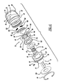
FIG. 4 is an exploded perspective view of the holesaw mandrel assembly ofFIG. 1 . -
FIG. 5 is a cross-section view ofFIG. 1 along line 5-5 thereof. -
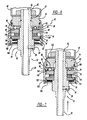
FIG. 6 is a cross-section view of an additional embodiment of the hole saw mandrel. -
FIG. 7 is a view likeFIG. 6 in a second position. -
FIG. 8 is an exploded perspective view of the hole saw mandrel assembly ofFIG. 6 . - The following description is merely exemplary in nature.
- Turning to the figures, a holesaw mandrel assembly is illustrated and designed with the
reference numeral 10. Theholesaw mandrel assembly 10 includes amandrel 12, a first axiallymovable member 14 and amechanism 16 for moving thefirst member 14 between a first hole saw contact and second hole saw release position. - The
mandrel 12 includes abody 18 with a first projectingend 20 and a second extendingend 22. The first projectingend 20 is cylindrical and may have an outer polygonal surface to connect the mandrel with a rotating tool, such as adrill 32. Thebody 18 has an overall cylindrical shape with a firstcylindrical portion 24 and a larger cylindrical shapedportion 26. The firstcylindrical portion 24 includes anaperture 28 to receive afastener 30 that retains apilot drill bit 32 in abore 34. Thedrill bit 32 extends through the second extendingmember 22. The secondcylindrical portion 26 includes aperipheral groove 36 that receives a sealing O-ring 38. - The second extending
end 22 of themandrel 12 includes a firstcylindrical portion 40 and a threadedspud 42. The threaded spud 42 receives aholesaw 45 in a conventional manner. The firstcylindrical portion 40 includes a pair offlat surfaces 46 that receive thefirst member 14. Thesurfaces 46 mate with surfaces in thefirst member 14 to enable thefirst member 14 to axially slide on the second extendingend 22 of themandrel 12. However, theflat surfaces 46 fix thefirst member 14 against rotation about the second extendingend 22 of themandrel 12. - The
first member 14 has an overall annular configuration. Thefirst member 14 includes abore 48 that extends through thefirst member 14. Thebore 48 enables thefirst member 14 to be positioned onto thesecond end 22 of themandrel 12. Thefirst member 14 includes a pair ofcylindrical portions cylindrical portion 50 extends from the secondcylindrical portion 52. Ashoulder 54 is formed between the twoportions bore 48, extending through thefirst portion 50, has a substantially circular configuration. The wall defining thebore 48, in the secondcylindrical portion 52, includes a pair offlat surfaces 56. The flat surfaces 56 mate with theflat surfaces 46 of thesecond end 22 of themandrel 12. Thus, the pair offlat surfaces first member 14 on thesecond end 22 of themandrel 12. - The second
cylindrical portion 52 includes acircumferential groove 58 that receives a sealing O-ring 60. Thecylindrical portion 52 includes a flat annularbottom surface 62. - The
mechanism 16 for moving thefirst member 14 between a first hole saw contact and second hole saw release position includes an outer sleeve orcollar 66. Thecollar 66 has an overall cylindrical shape with acentral bore 68. Thecollar 66 includes alip 70, at one end, that rests onshoulder 54 to retain the first member andmechanism 16 on themandrel 12. Thecollar 66 includes an internalcylindrical surface 72 that defines thebore 68. Theinternal surface 72 includes acavity 74 that includes aflat surface 76 that define a rectangular groove, to key or mate with atooth 80 on bearingrace 78. Also, the interior surface includes achannel 82 that receives a C-clip 84. The C-clip 84 is positioned behind the secondcylindrical body portion 26 to retain thefirst member 14 andmechanism 16 onto themandrel 12. - The bearing
race 78 includes acentral bore 86, with a circular configuration, that fits onto thecylindrical portion 40 of thesecond end 22 of themandrel 12. The bearingrace 78 includestooth 80 about its periphery. Thetooth 80 keys or mates with thecollar 66 for rotation with thecollar 66 about thesecond end 22. The bearingrace 78 includes twosurfaces surface 92 is flat. Thesurface 90 includes a plurality ofarcuate tracks 94 to receiveballs 96 that are retained by acage 98. The arcuate tracks 94 lead into, viaramps 99, pockets 100. A plurality ofpins 102 project from thesurface 90, the pins retain anend 104 of the circumferential springs 106. Theother end 108 of the circumferential springs 106 is retained on thecage 98. Thesprings 106 are positioned inslots 110 in thecage 98. Thecage 98 includes asmaller slot 112 that includespin 114, projecting fromsurface 90, to limit rotational movement of thecage 98 on the bearingrace 78. - A
thrust bearing 116 andwasher 118 are positioned below the bearingrace 78. Thewasher 118 abuts thecylindrical portion 26 of the mandrel body. Thethrust bearing 116 may be of the needle roller ball, or the like, bearing. Also, a thrust bearing made of a low friction material such as Teflon® may be used. Thethrust bearing 116 provides for a substantially friction free rotation of the bearingrace 78. - A plurality of rollers or
balls 96, preferably three, is positioned in thetracks 94 between thebearing race surface 90 and thefirst member 14, as best seen inFIGS. 2 and 3 . Therollers 96 are sandwiched between thetracks 94 and the flat bottom surface of thefirst member 14. The circumferential springs 106 are positioned to hold thecage 98 and bearingrace 78 against rotation and to return thefirst member 14 from a second position (FIG. 3 ) to its first original position (FIG. 2 ). - The
first member 14 androtational mechanism 16 are positioned onto themandrel 12 as illustrated inFIGS. 1-3 . The rollers orballs 96, in a first position, are positioned in thetracks 94 between thefirst member 14 and the bearingrace 78. At this time, aholesaw 45 is screwed onto the mandrel threadedspud 42. Theholesaw 45 is screwed onto thespud 42 until it contacts afriction surface 122 of thefirst member 14. This is illustrated inFIG. 2 . Theholesaw 45 andmandrel assembly 10 are now ready for use. After using theholesaw 45, theholesaw 45 may be quickly removed from themandrel assembly 10. However, due to rotation of the mandrel and the reverse torque caused between the holesaw 45 and the workpiece, there is a tendency for theholesaw 45 to tighten against thefriction face 122 of thefirst member 14. - Once the
holesaw 45 is used, and in order to remove it from themandrel assembly 10, thecollar 66 is rotated with respect to themandrel body 18. As thecollar 66 is rotated, the bearingrace 78, as well as thecage 98, is rotated with thecollar 66. As this occurs, the rollers orballs 96 roll along thetracks 94 of the bearingrace 70 and flat surface ofcylindrical portion 52, respectively, as illustrated inFIG. 2 . Also, thesprings 106 are compressed. Thecage 98 continues to rotate until thecage slot 112contacts pin 114. At this point, theballs 96 move down ramps 99 into thepockets 100. As this occurs, thefirst member 14 moves axially along the mandrelsecond end 22 away from theholesaw 45 toward the secondcylindrical portion 26 of themandrel body 18. As this happens, thefriction face 122 moves away from theholesaw 45. Thus, theholesaw 45 can be easily rotated and removed from the threaded spud 42. Thus, wrenches or tools are not required to remove theholesaw 45 from themandrel assembly 10. - After the holesaw is removed and the rotational force on the
collar 66 is released, the circumferential springs 106 return to their original condition in theslots 110 of thecage 98 to return the rollers orballs 96 back to their original position. Thus, themandrel assembly 10 is ready for additional use. - Turning to
FIGS. 6-8 , a second embodiment is illustrated. The second embodiment is similar to the first and thus the reference numerals used in the first embodiment will be used in the second to identify the same elements. The differences are in the mating connection between thecollar 66 and the bearingrace 78. - The mandrel assembly 10' is like that described above. The outer sleeve or
collar 66 differs in that it is devoid of a cavity. The internal cylindrical surface includes a plurality of projectingteeth 140. The plurality ofteeth 140 are spaced about the periphery of thecylindrical surface 72 so that upon rotation of thecollar 66, one of the plurality ofteeth 140 will mate or mesh withtooth 80 on bearingrace 78. The plurality ofteeth 140 each have an overall rectangular shape, however, any shape with aside surface 142 may be used. - Additionally, the mandrel assembly 10' includes a
biasing mechanism 150. Thebiasing mechanism 150 includes one or more compression springs 152. The compression springs 152 are sandwiched between the flat bottom surface of the larger cylindrical shapedportion 26 and awasher 154. The C-clip 84 is positioned behind thewasher 154 to retain thefirst member 14 andmechanism 16 onto themandrel 12. Thehole saw 45 is positioned onto the mandrel 10' and used as discussed above. Only the removal of the hole saw is different. - In order to remove the
hole saw 45, thecollar 66 is moved axially in a direction toward the threaded spud 42. As this occurs, thecompression spring 152 is compressed between the large cylindrical shapedportion 26 andwasher 154 as illustrated inFIGS. 6-8 . The plurality ofteeth 140 is moved axially toward thespud 42. The side surfaces 142 are aligned with theside surface 144 of thetooth 80. Thecollar 66 is rotated until one of the plurality ofteeth 140 mesh or key with the bearing racetooth side face 144. The bearingrace 78 is rotated as described above until theball 96 drop intopockets 100 enabling the hole saw 45 to be removed from the mandrel assembly 10' as described above. - Upon removal of the rotational force, the circumferential springs 106 move the
balls 96 along theramps 99 out ofpockets 100 back into tracks 94. As this occurs, simultaneously, thecompression spring 152 extends disengaging one of the pluralities ofteeth 140 from thetooth 80, returning thecollar 66 back to its original position. Thus, in its original disengaged position, thecollar 66 is enabled to be rotated with respect to themandrel body 12.
Claims (12)
- A hole saw mandrel assembly comprising:a mandrel having a body with a first end for coupling with a drill motor, a second end extending from said body, said second end including a thread for receiving a hole saw;a first member on said second end, said first member axially movable on said second end;a friction surface on said first member, said friction surface adapted for contacting a base surface on the hole saw such that the hole saw is fixed in position, said friction surface moving between a first contact and a second release position;a mechanism on said mandrel adjacent said first member for moving said friction surface between said first and second positions; andsaid mechanism including an auxiliary biased collar and a bearing race, said collar and bearing race having a mating mechanism for enabling rotation of said collar which, in turn, enables said friction surface to move between said contact and release positions.
- The mandrel assembly according to Claim 1, wherein said mating mechanism further comprises a pair of members, at least one member on said collar and at least one member on said bearing race.
- The mandrel assembly of Claim 1 or Claim 2, wherein a compression spring biases said collar.
- The mandrel assembly of any preceding claim, wherein said collar is moved toward said first end for engaging said mating mechanism.
- The mandrel assembly of any preceding claim, wherein upon release of a rotational force on said collar, said biasing mechanism returns said collar to its original position.
- The mandrel assembly of Claim 2 or any claim dependent thereon, wherein said collar has one member and said bearing race includes a plurality of members.
- The mandrel assembly of any preceding claim, wherein a plurality of rollers are between said first member and said bearing race, and said bearing race includes a plurality of pockets for receiving said plurality of rollers for enabling said friction surface to move axially from said first to said second position.
- A hole saw mandrel assembly comprising:a mandrel having a body with a first end for coupling with a drill motor, a second end extending from said body, said second end including a thread for receiving a hole saw;a cylindrical member on said second end, said first cylindrical member axially movable on said second end, a friction surface on said cylindrical member, said friction surface adapted for contacting a base surface of the hole saw such that the hole saw is fixed in position, said friction surface moving between a first contact and a second release position, a second surface on said cylindrical member, said second surface substantially parallel to said friction face;a mechanism on said mandrel adjacent said cylindrical member for moving said friction surface between said first and second positions, said mechanism comprising an axially biased collar and a bearing race, a plurality of balls are held by a cage, said plurality of balls are sandwiched between said cylindrical member second face and said bearing race, said bearing race including a track and a plurality of pockets along said track for receiving said plurality of balls, said collar having a plurality of mating projections extending radially inward from an inner surface of said collar, said bearing race having a mating member projecting radially outward from a circumferential surface of said bearing race for mating with one of said plurality of mating projections;a compression spring on said mandrel first end, said compression spring associated with said collar so that said collar is axially moved toward said second mandrel end compressing said compression spring, as said collar moves axially, said plurality of projections are aligned with said bearing race projection, said collar is rotated so that said projections mate with one another, said plurality of balls, in turn, move in said tracks until said plurality of balls drop into said pockets so that said friction surface axially moves toward said first end of said mandrel to its release position enabling removal of said hole saw.
- The mandrel assembly of Claim 8, wherein said cage includes a pair of return springs for rotating said collar back into position.
- The mandrel assembly of Claim 9, wherein said return springs are positioned in a slot in said cage, each spring having two ends, one end secured with said cage and the other end secured with a pin extending from said bearing race.
- The mandrel assembly of Claim 8 or any claim dependent thereon, wherein said cage and bearing race include a control mechanism for controlling travel of said cage with respect to said bearing race.
- The mandrel assembly of Claim 11, wherein said control mechanism includes a slot in said cage and a pin projecting from said bearing race into said slot.
Applications Claiming Priority (1)
| Application Number | Priority Date | Filing Date | Title |
|---|---|---|---|
| US12/408,052 US8434976B2 (en) | 2009-03-20 | 2009-03-20 | Small hole saw mandrel assembly |
Publications (1)
| Publication Number | Publication Date |
|---|---|
| EP2230038A1 true EP2230038A1 (en) | 2010-09-22 |
Family
ID=42235849
Family Applications (1)
| Application Number | Title | Priority Date | Filing Date |
|---|---|---|---|
| EP10156085A Withdrawn EP2230038A1 (en) | 2009-03-20 | 2010-03-10 | Small Hole Saw Mandrel Assembly |
Country Status (3)
| Country | Link |
|---|---|
| US (1) | US8434976B2 (en) |
| EP (1) | EP2230038A1 (en) |
| CN (1) | CN201664791U (en) |
Families Citing this family (13)
| Publication number | Priority date | Publication date | Assignee | Title |
|---|---|---|---|---|
| US8038372B2 (en) * | 2007-04-13 | 2011-10-18 | Black & Decker Inc. | Push button holesaw mandrel assembly |
| US8038371B2 (en) * | 2007-04-13 | 2011-10-18 | Black & Decker Inc. | Push button holesaw mandrel assembly |
| US8721236B2 (en) * | 2009-10-23 | 2014-05-13 | Milwaukee Electric Tool Corporation | Power tool arbor device |
| DE102012204491A1 (en) * | 2012-03-21 | 2013-09-26 | Hilti Aktiengesellschaft | drilling |
| US9192390B2 (en) * | 2012-12-14 | 2015-11-24 | DePuy Synthes Products, Inc. | Surgical saw blade |
| USD748700S1 (en) * | 2013-11-27 | 2016-02-02 | Nir Velozny | Construction drilling cup |
| USD748701S1 (en) * | 2013-11-27 | 2016-02-02 | Nir Velozny | Inner ring of a construction drilling cup |
| USD748170S1 (en) * | 2013-11-27 | 2016-01-26 | Nir Velozny | Connector for construction drilling cup |
| USD748702S1 (en) * | 2013-11-27 | 2016-02-02 | Nir Velozny | Accessory for inner ring of drilling cup and for housing of electrical appliances |
| US9782840B2 (en) * | 2014-07-01 | 2017-10-10 | James Edwin Funk | Safety drilling tool |
| US20200391338A1 (en) * | 2019-06-14 | 2020-12-17 | Nanjing Chervon Industry Co., Ltd. | Polishing machine |
| EP4313457A4 (en) * | 2021-04-02 | 2025-03-05 | Milwaukee Electric Tool Corporation | Core drill |
| US20230356434A1 (en) * | 2022-05-04 | 2023-11-09 | Milwaukee Electric Tool Corporation | Bit holder for a power tool |
Citations (2)
| Publication number | Priority date | Publication date | Assignee | Title |
|---|---|---|---|---|
| US20080118316A1 (en) | 2006-11-16 | 2008-05-22 | Miller Mark D | Small holesaw mandrel assembly |
| US20080253852A1 (en) * | 2007-04-13 | 2008-10-16 | Black & Decker Inc. | Push Button Holesaw Mandrel Assembly |
Family Cites Families (70)
| Publication number | Priority date | Publication date | Assignee | Title |
|---|---|---|---|---|
| DE7430652U (en) | 1974-12-12 | Hawera Probst Kg | Hollow drill bit | |
| DE1992344U (en) | 1968-08-22 | Impex Essen Gm b H , 8800 Ansbach | Drill with a bayonet-like shaft | |
| US2556155A (en) | 1946-07-13 | 1951-06-05 | Domnic V Stellin | Socket head screw |
| US2674026A (en) | 1952-07-05 | 1954-04-06 | Palley Zoltan O St | Hole saw |
| US2826231A (en) | 1953-09-03 | 1958-03-11 | Alden Milton | Screw mounting bracket for sheet metal and screw held captive therein |
| GB803797A (en) | 1955-09-29 | 1958-11-05 | Sheffield Twist Drill & Steel | Improvements in and relating to arbors for milling machine cutters and like rotary tools |
| US3262474A (en) | 1964-03-11 | 1966-07-26 | Black | Hole saw assembly |
| US3267975A (en) | 1964-06-16 | 1966-08-23 | Black & Decker Mfg Co | Coupling means for hole saw assembly |
| US3424212A (en) | 1967-04-12 | 1969-01-28 | United Co The | Screw wrench device |
| US3456548A (en) | 1967-11-22 | 1969-07-22 | Ideal Corp | Screw with hexagonal-collared slotted head |
| US3784316A (en) | 1972-07-12 | 1974-01-08 | Capewell Mfg Co | Hole saw and reversible quick disconnect drive therefor |
| US3778179A (en) | 1972-09-06 | 1973-12-11 | D Rivas | Dual replaceable holesaw bit |
| JPS5153514Y2 (en) | 1973-12-01 | 1976-12-21 | ||
| US3970407A (en) | 1974-11-25 | 1976-07-20 | Uffman Leroy E | Rotary cutter |
| US3973862A (en) | 1975-06-02 | 1976-08-10 | Segal F | Pilot drill locating means for hole saw assembly |
| US4148593A (en) | 1978-01-27 | 1979-04-10 | Stanadyne, Inc. | Hole saw assembly |
| US4461195A (en) | 1982-03-26 | 1984-07-24 | Barnick John F | Multi-machine cutter holder |
| DE3214209A1 (en) | 1982-04-17 | 1983-10-20 | Kaiser GmbH & Co KG, 5885 Schalksmühle | Apparatus for producing wall recesses for the retroactive fitting of sockets of an electric installation |
| ES2011266B3 (en) | 1986-02-05 | 1990-01-01 | Geissler & Kuper Gmbh Diamantwerkzeug-Wiederaufbereitung | COUPLING, ESPECIALLY FOR DIAMOND DRILL CROWNS, WITH REED TUBE AND TUBE THREAD CLOSURE. |
| DE3644440A1 (en) | 1986-12-24 | 1988-07-07 | Bosch Gmbh Robert | TENSIONING DEVICE FOR DETACHABLE FASTENING OF A TOOL, IN PARTICULAR A DISC |
| DE3705638C1 (en) | 1987-02-21 | 1988-09-08 | Bosch Gmbh Robert | Clamping device for axially clamping a disk-shaped tool, in particular a grinding wheel, on a flange of a driven spindle |
| DE3824040C1 (en) | 1987-02-21 | 1989-11-23 | Robert Bosch Gmbh, 7000 Stuttgart, De | Clamping device for axially clamping a tool, in particular a disk |
| US5108235A (en) | 1991-05-14 | 1992-04-28 | Greenlee Textron Inc. | Hole saw arbor |
| GB2257381A (en) | 1991-07-09 | 1993-01-13 | Eldon Tool Company Limited | Arbor for hole saw. |
| US5246317A (en) | 1991-12-31 | 1993-09-21 | American Saw & Mfg. Company | Quick-release arbor for hole saws |
| US5154552A (en) | 1991-12-31 | 1992-10-13 | American Saw & Mfg. Company | Quick-release arbor for hole saws |
| US5226762A (en) | 1992-08-06 | 1993-07-13 | Ecker Robert J | Sealed hole-saw arbor |
| US5352071A (en) | 1993-06-07 | 1994-10-04 | Greenlee Textron Inc. | Hole saw arbor with retaining mechanism |
| AU670373B2 (en) | 1993-06-30 | 1996-07-11 | Nitto Kohki Co., Ltd. | Annular cutter connecting apparatus and annular cutter |
| GB9423388D0 (en) | 1994-11-19 | 1995-01-11 | Eldon Eng Comp Ltd | Holesaw assembly |
| US5967709A (en) | 1995-01-31 | 1999-10-19 | Thuesen; Jorgen | Adaptor for rotating tools |
| DK0732164T3 (en) | 1995-03-17 | 2000-03-20 | Hawera Probst Gmbh | Drilling tools especially for rotary impact drilling, preferably in stone |
| US5624213A (en) | 1995-05-11 | 1997-04-29 | Evergreen Tool Co., Inc. | Hole producing assembly |
| DE29509238U1 (en) | 1995-06-03 | 1995-08-17 | Biedron, Ralf, 44879 Bochum | Centering drill holder for hollow drills |
| US5597274A (en) | 1995-08-17 | 1997-01-28 | Behner; Ray E. | Hole cutter |
| US5658102A (en) | 1995-09-12 | 1997-08-19 | The L. S. Starrett Company | Hole saw arbor method and apparatus |
| JP3520882B2 (en) * | 1995-10-18 | 2004-04-19 | 株式会社富士通ゼネラル | louver |
| US5813802A (en) | 1995-11-30 | 1998-09-29 | House B.M. Co., Ltd. | Drilling tool assembly and its center drill and cup shape drill |
| JP2922847B2 (en) | 1996-06-05 | 1999-07-26 | 株式会社ミヤナガ | Stopper for multi-stage bit |
| US5690452A (en) | 1996-06-27 | 1997-11-25 | Baublits; David G. | Spring loaded automatic plug ejector or hole saws |
| SE510841C2 (en) | 1996-12-19 | 1999-06-28 | Sandvik Ab | Hole saw |
| US5868532A (en) | 1997-03-24 | 1999-02-09 | American Saw & Mfg. Company | Arbor for engaging a saw |
| US5975816A (en) | 1997-07-09 | 1999-11-02 | Cook; Harold D. | Harmonic dampener for rotary tool holder |
| US5921562A (en) | 1998-01-27 | 1999-07-13 | Robison; Troy | Magnetic chuck assembly |
| US6328517B1 (en) | 1999-03-30 | 2001-12-11 | Gregory Steven Mann | Combination sidewalk bolt |
| TW422149U (en) | 1999-06-28 | 2001-02-11 | K & W Tools Co Ltd | Connecting device for hole-drilling saw |
| US6302409B1 (en) | 1999-09-10 | 2001-10-16 | Gunter Emil Gutsche | Elements for a magnetic tool holder system |
| DE29917867U1 (en) | 1999-10-11 | 2000-03-02 | Rabied Diamanttechnik GmbH, 44879 Bochum | Centering drill holder for hollow drills |
| US6705807B1 (en) | 1999-11-24 | 2004-03-16 | Black & Decker Inc. | Hole saw and connection method |
| EP1232034B1 (en) | 1999-11-24 | 2011-04-06 | Black & Decker Inc. | Arbor and hole saw assembly |
| US6341925B1 (en) | 2000-03-02 | 2002-01-29 | Roger J. Despres | Plug ejecting hole saw with twist-locking interchangeable saw cups |
| JP2002018613A (en) | 2000-06-30 | 2002-01-22 | Omi Kogyo Co Ltd | Cutter fixture, cutter and cutting unit |
| ATE376468T1 (en) | 2000-09-01 | 2007-11-15 | Credo Tech Corp | QUICK-RELEASE SPINDLE UNIT FOR HOLESAW AND DRILL |
| GB0026051D0 (en) | 2000-10-25 | 2000-12-13 | Universal Drilling And Cutting | Arbor |
| US20020122703A1 (en) | 2001-02-16 | 2002-09-05 | Peter Czyzewski | Quick change adaptor for hole saw |
| AUPR780301A0 (en) * | 2001-09-21 | 2001-10-11 | Keightley, Kym | Improved hole saw |
| DE10228103A1 (en) | 2002-06-24 | 2004-01-15 | Bayer Cropscience Ag | Fungicidal active ingredient combinations |
| DE10233365B4 (en) | 2002-07-23 | 2016-08-18 | Hilti Aktiengesellschaft | Tool holder for a core bit |
| DE10305707A1 (en) | 2003-02-12 | 2004-08-26 | Narex Česká Lípa a.s. | drilling |
| ATE482045T1 (en) | 2003-02-18 | 2010-10-15 | Greenlee Textron Inc | QUICK CHANGE SPINDLE UNIT FOR HOLE SAW |
| US6939092B2 (en) | 2003-06-18 | 2005-09-06 | Irwin Industrial Tool Company | Sheet metal hole cutter |
| US7563748B2 (en) | 2003-06-23 | 2009-07-21 | Cognis Ip Management Gmbh | Alcohol alkoxylate carriers for pesticide active ingredients |
| US7073992B2 (en) | 2003-06-24 | 2006-07-11 | Irwin Industrial Tool Company | Arbor for hole cutter and related method of use |
| GB2405115B (en) | 2003-08-22 | 2007-05-02 | Kym John Keightley | Hole-saw assembly including two hole-saws |
| DE102004020723B4 (en) | 2004-04-28 | 2016-06-23 | Thielenhaus Technologies Gmbh | Method and device for clamping and subsequent machining of a workpiece |
| JP4519514B2 (en) * | 2004-04-28 | 2010-08-04 | 株式会社マキタ | Fixing nut |
| TWM294374U (en) | 2006-01-11 | 2006-07-21 | K & W Tools Co Ltd | Hole cutter knife with quick-release function |
| JP4835293B2 (en) | 2006-07-13 | 2011-12-14 | 日本電気株式会社 | Transmission output control device, multi-carrier transmission system, transmission output control method, and transmission output control program |
| US7488146B2 (en) | 2006-11-16 | 2009-02-10 | Black & Decker Inc. | Large holesaw mandrel assembly |
| US8038371B2 (en) | 2007-04-13 | 2011-10-18 | Black & Decker Inc. | Push button holesaw mandrel assembly |
-
2009
- 2009-03-20 US US12/408,052 patent/US8434976B2/en not_active Expired - Fee Related
-
2010
- 2010-03-10 EP EP10156085A patent/EP2230038A1/en not_active Withdrawn
- 2010-03-19 CN CN201020147046.3U patent/CN201664791U/en not_active Expired - Fee Related
Patent Citations (2)
| Publication number | Priority date | Publication date | Assignee | Title |
|---|---|---|---|---|
| US20080118316A1 (en) | 2006-11-16 | 2008-05-22 | Miller Mark D | Small holesaw mandrel assembly |
| US20080253852A1 (en) * | 2007-04-13 | 2008-10-16 | Black & Decker Inc. | Push Button Holesaw Mandrel Assembly |
Also Published As
| Publication number | Publication date |
|---|---|
| US20100239381A1 (en) | 2010-09-23 |
| CN201664791U (en) | 2010-12-08 |
| US8434976B2 (en) | 2013-05-07 |
Similar Documents
| Publication | Publication Date | Title |
|---|---|---|
| US8434976B2 (en) | Small hole saw mandrel assembly | |
| EP1923161B1 (en) | Holesaw mandrel assembly | |
| US11154940B2 (en) | Hole saw arbor assembly | |
| US8721236B2 (en) | Power tool arbor device | |
| US9296046B2 (en) | Locking mechanism, and clamping head device and fastening clamp with locking mechanism | |
| US9555524B2 (en) | Clamping device for clamping a fastener | |
| EP1982785B1 (en) | Holesaw mandrel assembly | |
| US11173585B2 (en) | Shaft securing mechanism | |
| JP7545961B2 (en) | Wire driver chuck | |
| CA2650946C (en) | Coupling mechanisms for detachably engaging tool attachments | |
| US8038371B2 (en) | Push button holesaw mandrel assembly | |
| CN111906719A (en) | Adjustable ratchet wrench | |
| US4033022A (en) | Hand operated swager | |
| JP5416572B2 (en) | spanner | |
| JP4658254B2 (en) | Direct acting one-way clutch | |
| JP7539157B2 (en) | Tool Socket | |
| JP2004286086A (en) | Fastener | |
| US20260138246A1 (en) | Torque tool | |
| JP6265038B2 (en) | Fastening socket and socket switching method | |
| JPS5920912Y2 (en) | tap holding device | |
| JPH09225711A (en) | Tool holding device | |
| JPH01295767A (en) | Clamping torque control mechanism for power tool | |
| JPH01295768A (en) | Clamp torque control mechanism for power tool |
Legal Events
| Date | Code | Title | Description |
|---|---|---|---|
| PUAI | Public reference made under article 153(3) epc to a published international application that has entered the european phase |
Free format text: ORIGINAL CODE: 0009012 |
|
| AK | Designated contracting states |
Kind code of ref document: A1 Designated state(s): AT BE BG CH CY CZ DE DK EE ES FI FR GB GR HR HU IE IS IT LI LT LU LV MC MK MT NL NO PL PT RO SE SI SK SM TR |
|
| AX | Request for extension of the european patent |
Extension state: AL BA ME RS |
|
| 17P | Request for examination filed |
Effective date: 20110321 |
|
| 17Q | First examination report despatched |
Effective date: 20111201 |
|
| STAA | Information on the status of an ep patent application or granted ep patent |
Free format text: STATUS: THE APPLICATION IS DEEMED TO BE WITHDRAWN |
|
| 18D | Application deemed to be withdrawn |
Effective date: 20160315 |