EP2229809B1 - Spindelmäher - Google Patents
Spindelmäher Download PDFInfo
- Publication number
- EP2229809B1 EP2229809B1 EP09008138.1A EP09008138A EP2229809B1 EP 2229809 B1 EP2229809 B1 EP 2229809B1 EP 09008138 A EP09008138 A EP 09008138A EP 2229809 B1 EP2229809 B1 EP 2229809B1
- Authority
- EP
- European Patent Office
- Prior art keywords
- reel
- mower
- adjustment device
- carrier plate
- bedknife
- Prior art date
- Legal status (The legal status is an assumption and is not a legal conclusion. Google has not performed a legal analysis and makes no representation as to the accuracy of the status listed.)
- Active
Links
Images


Classifications
-
- A—HUMAN NECESSITIES
- A01—AGRICULTURE; FORESTRY; ANIMAL HUSBANDRY; HUNTING; TRAPPING; FISHING
- A01D—HARVESTING; MOWING
- A01D34/00—Mowers; Mowing apparatus of harvesters
- A01D34/01—Mowers; Mowing apparatus of harvesters characterised by features relating to the type of cutting apparatus
- A01D34/412—Mowers; Mowing apparatus of harvesters characterised by features relating to the type of cutting apparatus having rotating cutters
- A01D34/42—Mowers; Mowing apparatus of harvesters characterised by features relating to the type of cutting apparatus having rotating cutters having cutters rotating about a horizontal axis, e.g. cutting-cylinders
- A01D34/62—Other details
Definitions
- Non-contact type reel mower which operates with contact between the reel blades and the fixed cutting edge of the mower (often referred to as a “bedknife”) to sever grass by a contact shearing or scraping operation of the blades.
- a non-contact type reel mower which tend to be quieter and operates with a small gap between the reel cutting blades and the bedknife to avoid contact and to sever the grass by using a sharper edge against the resistance of the grass.
- One distinction between the non-contact type reel mowers and the contact type reel mowers is the hardness of the cutting blades.
- a contact mower may have cutting blades hardened to approximately 20 Rockwell C, while the cutting blades of a non-contact type mower may be above 40 Rockwell C.
- Optimizing the cutting performance of a non-contact type mower involves carefully setting and maintaining the small gap between the reel cutting blades and the bedknife. A certain degree of precision is typically required in setting the gap; if the gap is too large, than the cutting performance is compromised, and if the gap is too small, the reel cutting blades and the bedknife with their high level of hardness may damage (e.g.
- the rotational inertia of the cutting blade reel can effect the performance of a non-contact reel mower.
- a cutting blade reel with low rotational inertia tends to stall or jam when encountering items that are more difficult to cut than grass, such as weeds, crabgrass, sticks, mulch and the like.
- typical cutting blade reels that attempted to increase rotational inertia by making the cutting blade wider also tend to increase aerodynamic drag and wind resistance, resulting in a level of performance that is less than desired.
- an improved non-contact type reel mower having a cutting blade reel with high rotational inertia packaged in a standard size mower, and a cutting gap adjustment system that is top-mounted for accessibility and moves the position of the reel relative to a stationary bedknife for setting the gap of the mower with the bedknife forming a structural portion of the mower.
- US 4, 345,419 discloses a reel mower (see figure 1 ) with a frame (12), a reel (30) having an axle (28), a plurality of blades (32) helically disposed about the axis at a radial distance from the axis and one blade support member coupling the blades to the axle; a bedknife (20), the bedknife mounted to the frame (12); and an adjustment system (10) configured to move the reel relative to the bedknife, the adjustment system including a first reel carrier plate (18 left) and a second reel carrier plate (18 right) each having a first portion pivotally coupled to the frame (pivot 38), and a second portion rotatably supporting the axle (28), and a third portion having an adjustment device (26, 24, 22) configured to couple the third portion of the carrier plates to the frame.
- This invention relates to a reel mower as claimed in Claim 1.
- a reel mower includes a reel having a high rotational inertia.
- the reel includes an axle, a plurality of blades helically disposed about the axis at a radial distance from the axis, and a blade support member coupling the blades to the axle, in a manner that locates a majority of the mass of the reel at a location as far from the axle as possible, while still fitting within the size constraints of a standard size mower package.
- the reel has a diameter of approximately 175 mm and a length of approximately 460 mm, and the blades have a thickness of 4.5 mm and a width of approximately 30 mm wide.
- a cutting gap adjustment system for a reel mower includes generally parallel carrier plates having a forward end pivotally coupled at a forward end of the mower, and a mid portion that supports or carries the reel and a rearward end that is operably coupled to a chassis of the mower by an adjustment device.
- the plates operate as levers pivoting about the pivot points to raise and lower the reel relative to a fixed bedknife to adjust a gap between the reel and the bedknife when the adjustment device is actuated to raise or lower the rearward end of the plates.
- Location of the reel proximate the mid portion of the plates permits a relatively small amount of gap adjustment that corresponds to a relatively large amount of movement of the adjustment device.
- the adjustment device extends upwardly from the chassis to permit actuation by a user from the top of the mower. Adjusting the gap by moving the reel relative to a stationary bedknife, permits the bedknife to also serve as a structural member for the chassis of the mower.
- a reel mower 10 having a cutting blade reel 30 with a high polar moment of inertia, and a cutting gap adjustment system 50 for setting a gap or clearance between the cutting blades of the reel and a fixed cutting edge of the reel mower, according to an exemplary embodiment.
- a non-contact type reel mower 10 with a high rotational inertia cutting blade reel 30 and a cutting gap adjustment system 50 is shown according to an exemplary embodiment.
- the reel mower 10 includes a main chassis 12 with rear drive wheels 14 located rearward on the chassis 12 and smaller height-adjustment front wheels 16 are located forward on the chassis 12 (often referred to as a front-mount or front-throw reel mower).
- the front wheels 16 are interconnected by a cross member 18 so that the cutting elevation of the reel mower may be raised or lowered by adjusting a single handle 20 to effect an elevation change of both front wheels 16.
- the cutting blade reel 30 is shown located forward of (i.e.
- a fixed cutting blade (referred to herein as a bedknife 22) is mounted to the chassis 12 and positioned to interface with the rotating cutting blades 32 of the reel 30 through a small gap 24 to provide a non-contact shearing relationship.
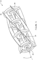
- Reel 30, concentrates mass away from the axis of rotation "A" to increase the rotational moment of inertia of the cutting blade reel 30.
- the rotational inertia of the reel 30 depends on at least several primary factors, including the length and diameter of the reel 30 and the mass of the blades 32.
- the reel 30 has a diameter of approximately 175 mm, and the blades 32 have a thickness "T" of 4.5 mm and a width "W" of approximately 30 mm wide, which are intended to place much of the reel's mass outward from the central axle 34 (and the corresponding axis of rotation A).
- a reel length i.e.
- the mass of the reel may be concentrated on some part other than the cutting blades of the reel.
- the reel may include thin, lightweight blades and weights mounted separately near the periphery of the reel.
- the blades may be mounted to a massive cylinder, itself mounted to the shaft, and providing a large area over which to distribute the mass distant from the axis of rotation.
- ring weights (e.g. toroidal weights, etc,) 38 may be mounted just inside of the edge of the cutting blade, and oriented approximately parallel to the spiders (see FIGURE 5 ).
- the cutting gap adjustment system 50 controls the size or dimension of the gap 24 (if present) or the amount of contact pressure between the cutting edge of the reel blades and the stationary bedknife (i.e. the fixed, opposing blade mounted on the bottom of the mower that engages the reel cutting blades in a shearing relationship). In both cases, careful control of the relative position of the reel cutting blades and bedknife is desirable for optimal performance of the mower. For contact mowers, a contact pressure that is too high results in both excessive power being needed to drive the reel and accelerated wear of the cutting edges. In contrast, a contact pressure that is too light results in failure of the blades to cut properly.
- a gap that is too large may result in a poor cut (or no cut at all), while contact between the cutting blades and bedknife tends to damage the cutting blades and bedknife.
- the difference between optimal performance and poor performance is generally understood to be a matter of a several thousandths of an inch at the interface between the blades and the bedknife.
- the reel 30 is movable relative to the main chassis 12 of the reel mower 10 to provide the desired adjustment of the gap 24 (or contact pressure in the case of a contact type mower).
- the reel 30 is supported by a pair of opposed reel carrier plates 52 disposed on opposite sides of the mower 10.
- Each reel carrier plate 52 is configured to pivot about a pivot point 54 disposed at a front end of the mower 10.
- the reel carrier plates 52 each include a forward end 58 and a rearward end 60, and a midportion 62.
- the forward end 58 of the plates 52 are pivotally coupled to the mower at pivot point 54.
- the rearward end 60 of the reel carrier plates 52 are coupled to the adjustment device 70, which engages the main chassis 12 of the mower 10 and extends upwardly from the mower 10.
- the adjustment device 70 is operable to raise or lower the rearward end 60 of the reel carrier plates 52 to raise or lower the reel 30 as the forward end 58 of the reel carrier plates 52 pivot about the pivot points 54.
- the adjustment devices 70 each comprise a pair of substantially vertical threaded members 72 (e.g. screws, etc.) that may be adjusted (i.e. rotated about their axis) to raise and lower the reel carrier plates 52 relative to the chassis 12.
- the reel carrier plates may be interconnected to permit adjustment of both reel carrier plates with a single (e.g. common, etc.) adjustment device.
- a cross-member or other substantially rigid framework
- a single adjustment device provided that operably engages the cross-member (or one of the reel carrier plates or framework) and the mower chassis, to adjust both reel carrier plates relative to the chassis and set the gap using a single adjustment operation, and also serves to maintain alignment of bearings 78 provided on opposite ends of the axle 34 for the reel 30.
- the bearings 78 are on (or within) the reel carrier plates 52 so that raising or lowering the rearward end 60 of the reel carrier plates 52 results in a desired change in elevation of the reel 30.
- the length of the reel carrier plates 52 are relatively long between the reel 30 and the adjustment device(s) 70 and relatively short between the reel 30 and the front pivot point 54, so that a 'coarse' adjustment of the threaded member 72 (corresponding to a relatively large elevation change at the rearward end 60 of the reel carrier plates 52) would result in a relatively small elevation change of the midportion 62 of the reel carrier plates 52 and the reel 30, and is intended to provide fine-tuning capability for the adjustment system.
- the motion-reducing nature of the reel carrier plates 52 that operate in the form of levers about a front pivot point 54 means that for a given pitch of the threaded member 72, a larger input motion is necessary to effect a given output at the reel 30, and is intended to reduce the sensitivity of the cutting gap adjustment system 50 to user "feel" and error.
- the reel 30 may be mounted approximately at a midpoint of the reel carriers plates 52, in order to provide the smallest overall length for the mower 10, while still providing an approximate 2-to-1 reduction in motion from the adjustment device(s) 70 to the reel 30.
- the adjustment devices 70 also include a locking device to fix the threaded members in place after adjustment of the gap 24 has been set, and is intended to minimize the drift, misalignment or other unintended change of the gap 24 (or contact pressure for contact type mowers).
- the gap 24 between the cutting blades 32 and the bedknife 22 is less than approximately 0.5 mm, and more particularly less than approximately 0.1 mm, and the reel cutting blades and bedlrnife are heat-treated to a hardness above approximately 40 Rockwell C, and more particularly above approximately 45 Rockwell C.
- suitable gap dimensions and cutting blade/bedknife hardness levels may be used as desired to suit a particular application.
- the adjustment device may omit the use of threaded members and include other adjustment features.
- fine intermeshing toothed racks may be provided on each of the chassis and the rearward end of the reel carrier plate(s) that may be 'snapped' from one discrete position to another, corresponding to predefined gaps dimensions.
- the rearward end of the reel carrier plates may be clamped into position with suitable clamps (e.g. bolts, over-center levers, etc.), that may be manually released to change the elevation or position of the reel and then tightened or engaged upon establishing the desired gap setting.
- the reel carriers may be made wholly or partly flexible (using a material such as fiberglass, carbon fiber or spring steel portions, etc.), such that when the flexible members are flexed (e.g. bowed, etc.) by the adjustment device, the amount of 'arch' of the members would also change and thereby cause an increased or decreased gap between cutting blades and the bedknife.
- the reel carrier plate(s) is (are) provided at their rearward end with a spring-biased rotatable cam (e.g. coupled to the plates by a common shaft or the like) that engages the chassis so that rotation of the cam raises or lowers the reel a pre-determined amount.
- a suitable locking device e.g. clamp, latch, travel-stop, etc. may also be provided to maintain the reel in a fixed position once the desired gap had been set.
- the cutting gap adjustment system 50 is mechanically simple, and allows for user adjustment of the gap 24 from the top of the mower 10 through a lever-type motion-reducing pivoted linkage to move the reel 30, without releasing the cutting blade reel or the bedknife) to free-float, which tends to make adjustment with a desired precision difficult without complex external fixtures.
- the system also allows the bedknife to serve as a chassis brace, reducing overall weight, complexity and cost for the mower.
Landscapes
- Life Sciences & Earth Sciences (AREA)
- Environmental Sciences (AREA)
- Harvester Elements (AREA)
Claims (15)
- Spindelmäher (10) mit:einem Rahmen (12) mit einem Vorderende (18), einem Hinterende, einem Paar von Vorderrädern (16), die nahe dem Vorderende (18) angebracht sind, und einem Paar von Hinterrädern (14), die nahe dem Hinterende angebracht sind,einer Spindel (30) mit einer Achse (34), einer Mehrzahl von helixförmig um die Achse in radialem Abstand zu der Achse angeordnete Messern (32) und wenigstens einem Messerträgerteil (36), das die Messer (32) mit der Achse (34) verbindet,einer Gegenschneide (22), wobei die Gegenschneide (22) an dem Rahmen (12) montiert ist, undeinem Einstellsystem (50), das dazu ausgestaltet ist, die Spindel (30) relativ zu der Gegenschneide (22) zu bewegen, wobei das Einstellsystem (50) eine erste Spindelträgerplatte (52) und eine zweite Spindelträgerplatte (52) aufweist, die jeweils einen ersten Bereich (54), der schwenkbar mit dem Rahmen (12) verbunden ist, und einem zweiten Bereich (62), in dem die Achse (34) drehbar gelagert ist, und einen dritten Bereich (60) mit einer Einstellvorrichtung (70) aufweist, die dazu ausgestaltet ist, um den dritten Bereich (60) der Trägerplatten (52) mit dem Rahmen (12) zu verbinden,dadurch gekennzeichnet, dass die Gegenschneide (22) eine Strebe für den Rahmen (12) bildet und dass das Einstellsystem (50) eine Federvorrichtung (74) aufweist, die die Spindelträgerplatten (52) in Anlage an die Einstellvorrichtung (70) vorspannt.
- Spindelmäher nach Anspruch 1, wobei der erste Bereich (54) der Trägerplatten (52) schwenkbar mit dem Vorderende (18) des Rahmens (12) gekoppelt sind und wobei die Vorderräder (16) einstellbar mit dem Vorderende (18) des Rahmens (12) gekoppelt sind.
- Spindelmäher nach Anspruch 1, wobei die Spindel (30) Masse in der Mehrzahl von Messern (32) konzentriert.
- Spindelmäher nach Anspruch 1, wobei die Spindel (30) nahe einem Mittelpunkt der Spindelträgerplatten (52) angebracht ist, um etwa eine zwei-zu-eins Reduktion in der Bewegung von der Einstellvorrichtung (70) zu der Spindel (30) zu schaffen.
- Spindelmäher nach Anspruch 1, wobei die Spindel (30) weiter mit einem Durchmesser von etwa 175 mm definiert ist und die Mehrzahl von Messern weiter mit einer Dicke von etwa 4,5 mm und einer Breite von etwa 30 mm und einer Länge von etwa 460 mm definiert sind, was in einem Spindelträgheitsmoment von wenigstens 5.000.000 g × mm2 resultiert.
- Spindelmäher nach Anspruch 1, wobei das Einstellsystem (50) zum Bewegen der Spindel (30) relativ zu der feststehenden Gegenschneide aufweist:die erste Trägerplatte (52) im Wesentlichen gegenüber und auf Abstand zu der zweiten Trägerplatte (52), wobei die erste Trägerplatte (52) und die zweite Trägerplatte (52) jede ein vorderes Ende (54), das schwenkbar nahe einem vorderen Ende (18) des Mähers gekoppelt ist, und einen Mittelbereich (62) mit einem in der Trägerplatte (52) angeordneten Lager, das die Spindel (30) drehbar lagert, und ein hinteres Ende aufweist, unddie Einstellvorrichtung (70), die nahe der Oberseite des Mähers angeordnet ist und das hintere Ende der Trägerplatten (52) beweglich mit einem Mäherrahmen (12) koppelt.
- Spindelmäher nach Anspruch 6, wobei die Einstellvorrichtung (70) weiter eine erste Einstellvorrichtung (70), die mit der ersten Trägerplatte (52) gekoppelt ist, und eine zweite Einstellvorrichtung (70) aufweist, die mit der zweiten Trägerplatte (52) gekoppelt ist, wobei die erste Einstellvorrichtung (70) dazu gestaltet ist, um das hintere Ende der ersten Trägerplatte (52) zu bewegen, und wobei die zweite Einstellvorrichtung (70) dazu ausgestaltet ist, um das hintere Ende der zweiten Trägerplatte (52) zu bewegen.
- Spindelmäher nach Anspruch 6, wobei Bewegung der Einstellvorrichtung (70) an den hinteren Enden der Trägerplatten (52) eine einstellbare Lücke (24) zwischen der Spindel (30) und der Gegenschneide (22) bildet.
- Spindelmäher nach Anspruch 6, wobei die Einstellvorrichtung (70) weiter eine Vorrichtung aufweist, um automatisch die Lücke zwischen der Spindel (30) und der Gegenschneide (22) festzulegen.
- Spindelmäher nach Anspruch 6, wobei die Einstellvorrichtung (70) der ersten Trägerplatte (52) und die Einstellvorrichtung (70) der zweiten Trägerplatte (52) von dem Rahmen (12) nach oben verlaufen.
- Spindelmäher nach Anspruch 10, wobei die Einstellvorrichtung (70) der ersten Trägerplatte (52) und die Einstellvorrichtung (70) der zweiten Trägerplatte (52) jeweils ein Paar von vertikalen Gewindegliedern (72) aufweisen.
- Spindelmäher nach Anspruch 11, wobei die Einstellvorrichtung (70) der ersten Trägerplatte (52) und die Einstellvorrichtung (70) der zweiten Trägerplatte (52) jeweils weiter eine Verriegelungsvorrichtung aufweisen, um die Trägerplatten (52) am Ort zu fixieren.
- Spindelmäher nach Anspruch 11, wobei die Einstellvorrichtung (70) weiter Federn (74) aufweist, um die hinteren Enden der Spindelträgerplatten (52) nach oben gegen die Gewindeglieder (72) vorzuspannen.
- Spindelmäher nach Anspruch 11, wobei die Gewindeglieder (72) jeweils einen ergonomischen Knauf (76) aufweisen.
- Spindelmäher nach Anspruch 7, wobei Bewegung der Einstellvorrichtung (70) an den hinteren Enden der Trägerplatten (52) über eine erste Strecke in Bewegung der Spindel (30) über eine zweite Strecke resultiert, wobei die erste Strecke größer als die zweite Strecke ist.
Applications Claiming Priority (2)
| Application Number | Priority Date | Filing Date | Title |
|---|---|---|---|
| US21055209P | 2009-03-20 | 2009-03-20 | |
| US12/466,289 US20100236209A1 (en) | 2009-03-20 | 2009-05-14 | Reel mower |
Publications (2)
| Publication Number | Publication Date |
|---|---|
| EP2229809A1 EP2229809A1 (de) | 2010-09-22 |
| EP2229809B1 true EP2229809B1 (de) | 2017-01-11 |
Family
ID=42358266
Family Applications (1)
| Application Number | Title | Priority Date | Filing Date |
|---|---|---|---|
| EP09008138.1A Active EP2229809B1 (de) | 2009-03-20 | 2009-06-22 | Spindelmäher |
Country Status (5)
| Country | Link |
|---|---|
| US (1) | US20100236209A1 (de) |
| EP (1) | EP2229809B1 (de) |
| AU (1) | AU2009202503A1 (de) |
| CA (1) | CA2669592A1 (de) |
| HU (1) | HUE032521T2 (de) |
Cited By (1)
| Publication number | Priority date | Publication date | Assignee | Title |
|---|---|---|---|---|
| WO2024064719A1 (en) * | 2022-09-20 | 2024-03-28 | Turf Equipment Services, Llc | Reel lawnmower for mowing greens |
Families Citing this family (6)
| Publication number | Priority date | Publication date | Assignee | Title |
|---|---|---|---|---|
| GB2491384A (en) * | 2011-06-02 | 2012-12-05 | Ken Roberts | Cutter for a lawnmower |
| USD651218S1 (en) | 2011-06-13 | 2011-12-27 | Fiskars Brands, Inc. | Reel mower |
| USD651217S1 (en) | 2011-06-13 | 2011-12-27 | Fiskars Brands, Inc. | Reel mower |
| JP6660153B2 (ja) * | 2015-11-12 | 2020-03-04 | 株式会社マキタ | 芝刈機 |
| USD787562S1 (en) * | 2016-05-05 | 2017-05-23 | Tami Dion Harrison | Reel weed trimmer |
| USD787563S1 (en) * | 2016-06-02 | 2017-05-23 | Tami Dion Harrison | Reel weed trimmer |
Family Cites Families (30)
| Publication number | Priority date | Publication date | Assignee | Title |
|---|---|---|---|---|
| US2209309A (en) * | 1938-10-20 | 1940-07-30 | Motor Mower Company | Lawn mower |
| US2266307A (en) * | 1939-02-14 | 1941-12-16 | Clemson Bros Inc | Mower |
| US2319038A (en) * | 1939-02-25 | 1943-05-11 | Clemson Bros Inc | Mower |
| US2671300A (en) * | 1950-12-18 | 1954-03-09 | Robert S Kinkead | Mower having integral frame |
| US2827752A (en) * | 1955-02-15 | 1958-03-25 | Clemson Bros Inc | Rotary reel with concave cutting blades |
| US2972218A (en) * | 1958-05-23 | 1961-02-21 | Toro Mfg Corp | Power mower with full floating cutting unit |
| US3106813A (en) * | 1961-04-17 | 1963-10-15 | Jacobsen Mfg Co | Reel type lawn mower cutting adjustment |
| US3357715A (en) * | 1966-02-10 | 1967-12-12 | M T & D Company | Mower having wheel adjustable means |
| US3576097A (en) * | 1968-10-17 | 1971-04-27 | Toro Mfg Corp | Adjustable reel mower |
| US3673773A (en) * | 1968-12-12 | 1972-07-04 | Reel Vortex Inc | Cross-flow mowing machine |
| US3604189A (en) * | 1969-09-18 | 1971-09-14 | Sperry Rand Corp | Knife mounting on a rotary mower |
| NL6914592A (de) * | 1969-09-26 | 1971-03-30 | ||
| US3581480A (en) * | 1969-09-30 | 1971-06-01 | Black & Decker Mfg Co | Multiple-function receptacle and interconnecting plugs therefor |
| US3613340A (en) * | 1970-04-09 | 1971-10-19 | Jacobsen Mfg Co | Tractor-driven lawn mower |
| US3638405A (en) * | 1970-08-06 | 1972-02-01 | Reel Vortex Inc | Lawnmower suspension |
| GB1454162A (en) * | 1972-12-11 | 1976-10-27 | Suffolk Lawn Mowers Ltd | Lawn mowers |
| GB1437261A (en) * | 1973-03-28 | 1976-05-26 | Ransomes Sims & Jefferies Ltd | Lawn mowers |
| US4109447A (en) * | 1976-11-11 | 1978-08-29 | Ferguson Hugo S | Mower of the cross-flow blower type with blades of opposite helix angle |
| US4345419A (en) * | 1981-03-31 | 1982-08-24 | Noel Chandler | Self adjusting, floating, reel blade mower |
| US4663924A (en) * | 1985-09-27 | 1987-05-12 | Textron Inc. | Apparatus and method for establishing reel-to-bedknife clearance |
| US4653256A (en) * | 1985-11-15 | 1987-03-31 | Textron Inc. | Apparatus for establishing reel-to-bedknife clearance |
| US4785612A (en) * | 1987-07-24 | 1988-11-22 | Yamaha Hatsudoki Kabushiki Kaisha | Walk-behind lawn mower |
| US4905463A (en) * | 1988-12-02 | 1990-03-06 | Canadiana Outdoor Products Inc. | Single action wheel height adjuster |
| GB9100264D0 (en) * | 1991-01-07 | 1991-02-20 | Ransomes Sims & Jefferies Ltd | Mechanical adjuster |
| US5170613A (en) * | 1991-10-15 | 1992-12-15 | Deere & Company | Reel motor cutting unit frame |
| US5241810A (en) * | 1992-06-05 | 1993-09-07 | Deere & Company | Height of cot adjustment mechanism for reel mowers |
| US5400576A (en) * | 1993-06-21 | 1995-03-28 | Smith; Jerry R. | Mulching device for reel-type lawn mowers |
| US7007446B2 (en) * | 2000-10-26 | 2006-03-07 | Textron Inc. | Battery-powered walk-behind greensmower |
| US7121073B2 (en) * | 2003-04-30 | 2006-10-17 | Deere & Company | Cutting reel adjusting system |
| US8087226B2 (en) * | 2008-12-17 | 2012-01-03 | Deere & Company | Detent spring on adjustment mechanism for reel-to-bedknife clearance |
-
2009
- 2009-05-14 US US12/466,289 patent/US20100236209A1/en not_active Abandoned
- 2009-06-18 CA CA2669592A patent/CA2669592A1/en not_active Abandoned
- 2009-06-22 EP EP09008138.1A patent/EP2229809B1/de active Active
- 2009-06-22 HU HUE09008138A patent/HUE032521T2/hu unknown
- 2009-06-23 AU AU2009202503A patent/AU2009202503A1/en not_active Abandoned
Non-Patent Citations (1)
| Title |
|---|
| None * |
Cited By (1)
| Publication number | Priority date | Publication date | Assignee | Title |
|---|---|---|---|---|
| WO2024064719A1 (en) * | 2022-09-20 | 2024-03-28 | Turf Equipment Services, Llc | Reel lawnmower for mowing greens |
Also Published As
| Publication number | Publication date |
|---|---|
| US20100236209A1 (en) | 2010-09-23 |
| HUE032521T2 (hu) | 2017-09-28 |
| CA2669592A1 (en) | 2010-09-20 |
| EP2229809A1 (de) | 2010-09-22 |
| AU2009202503A1 (en) | 2010-10-07 |
Similar Documents
| Publication | Publication Date | Title |
|---|---|---|
| EP2229809B1 (de) | Spindelmäher | |
| US11533842B2 (en) | Grounds maintenance vehicle with adjustable implement angle | |
| US20240397860A1 (en) | Grounds maintenance vehicle with adjustable implement angle | |
| US7631479B2 (en) | Adjustable pivot axis for bedknife assembly | |
| US2608043A (en) | Combined mower and trimmer | |
| US7013626B1 (en) | Walk behind mower | |
| US9288940B2 (en) | Lawn mower with transport lock | |
| US7963092B2 (en) | Trimmer with cutting height adjustment | |
| EP3794925B1 (de) | Mähwerkhebevorrichtung und mäher mit mähwerkhebevorrichtung | |
| EP2491781B1 (de) | Mäher | |
| JP2018530329A (ja) | 歩行型リール芝刈り機 | |
| US20150101302A1 (en) | String Trimmer Rack Apparatus with Foot Control for Zero-turn Lawn Mower | |
| US9027318B2 (en) | Reel lawn mower with main body, reel cutting unit, and connection structure for connecting reel cutting unit to main body such that reel cutting unit is rollable | |
| US3977163A (en) | Mower-height-of-cut adjustment mechanism | |
| EP2198685B1 (de) | Einstellungsmechanismus für Abstand zwischen Trommel und Gegenschneide | |
| US6339918B1 (en) | Lawn mower height adjustment | |
| US2862344A (en) | Lawnmower edger attachment | |
| US3217479A (en) | Combined height adjustment for reel mower | |
| US10939615B2 (en) | Adjustable mower deck | |
| JP2015514419A (ja) | フレイル草刈機およびフレイル草刈機用のリンク機構 | |
| GB2287170A (en) | Rotary lawnmowers | |
| US2794308A (en) | Rotary reel mower with a caster wheel assembly | |
| US7325387B2 (en) | Riding-type mower | |
| US2319483A (en) | Lawn mower | |
| US2712719A (en) | Lawn edger |
Legal Events
| Date | Code | Title | Description |
|---|---|---|---|
| PUAI | Public reference made under article 153(3) epc to a published international application that has entered the european phase |
Free format text: ORIGINAL CODE: 0009012 |
|
| AK | Designated contracting states |
Kind code of ref document: A1 Designated state(s): AT BE BG CH CY CZ DE DK EE ES FI FR GB GR HR HU IE IS IT LI LT LU LV MC MK MT NL NO PL PT RO SE SI SK TR |
|
| AX | Request for extension of the european patent |
Extension state: AL BA RS |
|
| 17P | Request for examination filed |
Effective date: 20110318 |
|
| 17Q | First examination report despatched |
Effective date: 20151019 |
|
| GRAP | Despatch of communication of intention to grant a patent |
Free format text: ORIGINAL CODE: EPIDOSNIGR1 |
|
| INTG | Intention to grant announced |
Effective date: 20160712 |
|
| GRAJ | Information related to disapproval of communication of intention to grant by the applicant or resumption of examination proceedings by the epo deleted |
Free format text: ORIGINAL CODE: EPIDOSDIGR1 |
|
| INTC | Intention to grant announced (deleted) | ||
| GRAS | Grant fee paid |
Free format text: ORIGINAL CODE: EPIDOSNIGR3 |
|
| GRAP | Despatch of communication of intention to grant a patent |
Free format text: ORIGINAL CODE: EPIDOSNIGR1 |
|
| GRAA | (expected) grant |
Free format text: ORIGINAL CODE: 0009210 |
|
| INTG | Intention to grant announced |
Effective date: 20161124 |
|
| AK | Designated contracting states |
Kind code of ref document: B1 Designated state(s): AT BE BG CH CY CZ DE DK EE ES FI FR GB GR HR HU IE IS IT LI LT LU LV MC MK MT NL NO PL PT RO SE SI SK TR |
|
| REG | Reference to a national code |
Ref country code: GB Ref legal event code: FG4D |
|
| REG | Reference to a national code |
Ref country code: CH Ref legal event code: EP |
|
| REG | Reference to a national code |
Ref country code: AT Ref legal event code: REF Ref document number: 860388 Country of ref document: AT Kind code of ref document: T Effective date: 20170115 |
|
| REG | Reference to a national code |
Ref country code: IE Ref legal event code: FG4D |
|
| REG | Reference to a national code |
Ref country code: DE Ref legal event code: R096 Ref document number: 602009043637 Country of ref document: DE |
|
| REG | Reference to a national code |
Ref country code: LT Ref legal event code: MG4D |
|
| REG | Reference to a national code |
Ref country code: FR Ref legal event code: PLFP Year of fee payment: 9 |
|
| REG | Reference to a national code |
Ref country code: NL Ref legal event code: MP Effective date: 20170111 |
|
| REG | Reference to a national code |
Ref country code: AT Ref legal event code: MK05 Ref document number: 860388 Country of ref document: AT Kind code of ref document: T Effective date: 20170111 |
|
| PG25 | Lapsed in a contracting state [announced via postgrant information from national office to epo] |
Ref country code: NL Free format text: LAPSE BECAUSE OF FAILURE TO SUBMIT A TRANSLATION OF THE DESCRIPTION OR TO PAY THE FEE WITHIN THE PRESCRIBED TIME-LIMIT Effective date: 20170111 |
|
| PG25 | Lapsed in a contracting state [announced via postgrant information from national office to epo] |
Ref country code: IS Free format text: LAPSE BECAUSE OF FAILURE TO SUBMIT A TRANSLATION OF THE DESCRIPTION OR TO PAY THE FEE WITHIN THE PRESCRIBED TIME-LIMIT Effective date: 20170511 Ref country code: HR Free format text: LAPSE BECAUSE OF FAILURE TO SUBMIT A TRANSLATION OF THE DESCRIPTION OR TO PAY THE FEE WITHIN THE PRESCRIBED TIME-LIMIT Effective date: 20170111 Ref country code: GR Free format text: LAPSE BECAUSE OF FAILURE TO SUBMIT A TRANSLATION OF THE DESCRIPTION OR TO PAY THE FEE WITHIN THE PRESCRIBED TIME-LIMIT Effective date: 20170412 Ref country code: NO Free format text: LAPSE BECAUSE OF FAILURE TO SUBMIT A TRANSLATION OF THE DESCRIPTION OR TO PAY THE FEE WITHIN THE PRESCRIBED TIME-LIMIT Effective date: 20170411 Ref country code: LT Free format text: LAPSE BECAUSE OF FAILURE TO SUBMIT A TRANSLATION OF THE DESCRIPTION OR TO PAY THE FEE WITHIN THE PRESCRIBED TIME-LIMIT Effective date: 20170111 |
|
| PG25 | Lapsed in a contracting state [announced via postgrant information from national office to epo] |
Ref country code: LV Free format text: LAPSE BECAUSE OF FAILURE TO SUBMIT A TRANSLATION OF THE DESCRIPTION OR TO PAY THE FEE WITHIN THE PRESCRIBED TIME-LIMIT Effective date: 20170111 Ref country code: PL Free format text: LAPSE BECAUSE OF FAILURE TO SUBMIT A TRANSLATION OF THE DESCRIPTION OR TO PAY THE FEE WITHIN THE PRESCRIBED TIME-LIMIT Effective date: 20170111 Ref country code: ES Free format text: LAPSE BECAUSE OF FAILURE TO SUBMIT A TRANSLATION OF THE DESCRIPTION OR TO PAY THE FEE WITHIN THE PRESCRIBED TIME-LIMIT Effective date: 20170111 Ref country code: SE Free format text: LAPSE BECAUSE OF FAILURE TO SUBMIT A TRANSLATION OF THE DESCRIPTION OR TO PAY THE FEE WITHIN THE PRESCRIBED TIME-LIMIT Effective date: 20170111 Ref country code: AT Free format text: LAPSE BECAUSE OF FAILURE TO SUBMIT A TRANSLATION OF THE DESCRIPTION OR TO PAY THE FEE WITHIN THE PRESCRIBED TIME-LIMIT Effective date: 20170111 Ref country code: PT Free format text: LAPSE BECAUSE OF FAILURE TO SUBMIT A TRANSLATION OF THE DESCRIPTION OR TO PAY THE FEE WITHIN THE PRESCRIBED TIME-LIMIT Effective date: 20170511 Ref country code: BG Free format text: LAPSE BECAUSE OF FAILURE TO SUBMIT A TRANSLATION OF THE DESCRIPTION OR TO PAY THE FEE WITHIN THE PRESCRIBED TIME-LIMIT Effective date: 20170411 |
|
| REG | Reference to a national code |
Ref country code: HU Ref legal event code: AG4A Ref document number: E032521 Country of ref document: HU |
|
| REG | Reference to a national code |
Ref country code: DE Ref legal event code: R097 Ref document number: 602009043637 Country of ref document: DE |
|
| PG25 | Lapsed in a contracting state [announced via postgrant information from national office to epo] |
Ref country code: RO Free format text: LAPSE BECAUSE OF FAILURE TO SUBMIT A TRANSLATION OF THE DESCRIPTION OR TO PAY THE FEE WITHIN THE PRESCRIBED TIME-LIMIT Effective date: 20170111 Ref country code: IT Free format text: LAPSE BECAUSE OF FAILURE TO SUBMIT A TRANSLATION OF THE DESCRIPTION OR TO PAY THE FEE WITHIN THE PRESCRIBED TIME-LIMIT Effective date: 20170111 Ref country code: SK Free format text: LAPSE BECAUSE OF FAILURE TO SUBMIT A TRANSLATION OF THE DESCRIPTION OR TO PAY THE FEE WITHIN THE PRESCRIBED TIME-LIMIT Effective date: 20170111 Ref country code: EE Free format text: LAPSE BECAUSE OF FAILURE TO SUBMIT A TRANSLATION OF THE DESCRIPTION OR TO PAY THE FEE WITHIN THE PRESCRIBED TIME-LIMIT Effective date: 20170111 |
|
| PLBE | No opposition filed within time limit |
Free format text: ORIGINAL CODE: 0009261 |
|
| STAA | Information on the status of an ep patent application or granted ep patent |
Free format text: STATUS: NO OPPOSITION FILED WITHIN TIME LIMIT |
|
| PG25 | Lapsed in a contracting state [announced via postgrant information from national office to epo] |
Ref country code: DK Free format text: LAPSE BECAUSE OF FAILURE TO SUBMIT A TRANSLATION OF THE DESCRIPTION OR TO PAY THE FEE WITHIN THE PRESCRIBED TIME-LIMIT Effective date: 20170111 |
|
| 26N | No opposition filed |
Effective date: 20171012 |
|
| PG25 | Lapsed in a contracting state [announced via postgrant information from national office to epo] |
Ref country code: MC Free format text: LAPSE BECAUSE OF FAILURE TO SUBMIT A TRANSLATION OF THE DESCRIPTION OR TO PAY THE FEE WITHIN THE PRESCRIBED TIME-LIMIT Effective date: 20170111 |
|
| REG | Reference to a national code |
Ref country code: CH Ref legal event code: PL |
|
| GBPC | Gb: european patent ceased through non-payment of renewal fee |
Effective date: 20170622 |
|
| PG25 | Lapsed in a contracting state [announced via postgrant information from national office to epo] |
Ref country code: SI Free format text: LAPSE BECAUSE OF FAILURE TO SUBMIT A TRANSLATION OF THE DESCRIPTION OR TO PAY THE FEE WITHIN THE PRESCRIBED TIME-LIMIT Effective date: 20170111 |
|
| REG | Reference to a national code |
Ref country code: IE Ref legal event code: MM4A |
|
| PG25 | Lapsed in a contracting state [announced via postgrant information from national office to epo] |
Ref country code: HU Free format text: LAPSE BECAUSE OF NON-PAYMENT OF DUE FEES Effective date: 20170623 Ref country code: LU Free format text: LAPSE BECAUSE OF NON-PAYMENT OF DUE FEES Effective date: 20170622 Ref country code: LI Free format text: LAPSE BECAUSE OF NON-PAYMENT OF DUE FEES Effective date: 20170630 Ref country code: CH Free format text: LAPSE BECAUSE OF NON-PAYMENT OF DUE FEES Effective date: 20170630 Ref country code: GB Free format text: LAPSE BECAUSE OF NON-PAYMENT OF DUE FEES Effective date: 20170622 Ref country code: IE Free format text: LAPSE BECAUSE OF NON-PAYMENT OF DUE FEES Effective date: 20170622 |
|
| REG | Reference to a national code |
Ref country code: BE Ref legal event code: MM Effective date: 20170630 |
|
| REG | Reference to a national code |
Ref country code: FR Ref legal event code: PLFP Year of fee payment: 10 |
|
| PG25 | Lapsed in a contracting state [announced via postgrant information from national office to epo] |
Ref country code: BE Free format text: LAPSE BECAUSE OF NON-PAYMENT OF DUE FEES Effective date: 20170630 |
|
| PG25 | Lapsed in a contracting state [announced via postgrant information from national office to epo] |
Ref country code: MT Free format text: LAPSE BECAUSE OF NON-PAYMENT OF DUE FEES Effective date: 20170622 |
|
| PG25 | Lapsed in a contracting state [announced via postgrant information from national office to epo] |
Ref country code: CY Free format text: LAPSE BECAUSE OF NON-PAYMENT OF DUE FEES Effective date: 20170111 |
|
| PG25 | Lapsed in a contracting state [announced via postgrant information from national office to epo] |
Ref country code: MK Free format text: LAPSE BECAUSE OF FAILURE TO SUBMIT A TRANSLATION OF THE DESCRIPTION OR TO PAY THE FEE WITHIN THE PRESCRIBED TIME-LIMIT Effective date: 20170111 |
|
| PG25 | Lapsed in a contracting state [announced via postgrant information from national office to epo] |
Ref country code: TR Free format text: LAPSE BECAUSE OF FAILURE TO SUBMIT A TRANSLATION OF THE DESCRIPTION OR TO PAY THE FEE WITHIN THE PRESCRIBED TIME-LIMIT Effective date: 20170111 |
|
| PGFP | Annual fee paid to national office [announced via postgrant information from national office to epo] |
Ref country code: CZ Payment date: 20200525 Year of fee payment: 12 |
|
| PGFP | Annual fee paid to national office [announced via postgrant information from national office to epo] |
Ref country code: FI Payment date: 20210617 Year of fee payment: 13 |
|
| PG25 | Lapsed in a contracting state [announced via postgrant information from national office to epo] |
Ref country code: CZ Free format text: LAPSE BECAUSE OF NON-PAYMENT OF DUE FEES Effective date: 20210622 |
|
| REG | Reference to a national code |
Ref country code: FI Ref legal event code: MAE |
|
| PG25 | Lapsed in a contracting state [announced via postgrant information from national office to epo] |
Ref country code: FI Free format text: LAPSE BECAUSE OF NON-PAYMENT OF DUE FEES Effective date: 20220622 |
|
| P01 | Opt-out of the competence of the unified patent court (upc) registered |
Effective date: 20230825 |
|
| PGFP | Annual fee paid to national office [announced via postgrant information from national office to epo] |
Ref country code: DE Payment date: 20250618 Year of fee payment: 17 |
|
| PGFP | Annual fee paid to national office [announced via postgrant information from national office to epo] |
Ref country code: FR Payment date: 20250617 Year of fee payment: 17 |