EP2229525B1 - Motor vehicle comprising a recirculated-gas circuit, and method for implementing same - Google Patents
Motor vehicle comprising a recirculated-gas circuit, and method for implementing same Download PDFInfo
- Publication number
- EP2229525B1 EP2229525B1 EP08855770A EP08855770A EP2229525B1 EP 2229525 B1 EP2229525 B1 EP 2229525B1 EP 08855770 A EP08855770 A EP 08855770A EP 08855770 A EP08855770 A EP 08855770A EP 2229525 B1 EP2229525 B1 EP 2229525B1
- Authority
- EP
- European Patent Office
- Prior art keywords
- circuit
- cooling
- hydraulic
- egr
- heat exchanger
- Prior art date
- Legal status (The legal status is an assumption and is not a legal conclusion. Google has not performed a legal analysis and makes no representation as to the accuracy of the status listed.)
- Active
Links
- 238000000034 method Methods 0.000 title abstract description 5
- 239000007789 gas Substances 0.000 claims abstract description 58
- 238000004378 air conditioning Methods 0.000 claims abstract description 47
- 239000002826 coolant Substances 0.000 claims abstract description 27
- 239000012530 fluid Substances 0.000 claims abstract description 15
- 238000001816 cooling Methods 0.000 claims description 49
- 238000003860 storage Methods 0.000 claims description 36
- 239000007788 liquid Substances 0.000 claims description 22
- 239000003507 refrigerant Substances 0.000 claims description 19
- 238000002485 combustion reaction Methods 0.000 claims description 8
- 230000002441 reversible effect Effects 0.000 claims description 4
- YBGRCYCEEDOTDH-JYNQXTMKSA-N evap protocol Chemical compound O=C1C=C[C@]2(C)[C@H]3[C@@H](O)C[C@](C)([C@@](CC4)(O)C(=O)CO)[C@@H]4[C@@H]3CCC2=C1.O([C@H]1C[C@@](O)(CC=2C(O)=C3C(=O)C=4C=CC=C(C=4C(=O)C3=C(O)C=21)OC)C(=O)CO)[C@H]1C[C@H](N)[C@H](O)[C@H](C)O1.COC1=C(O)C(OC)=CC([C@@H]2C3=CC=4OCOC=4C=C3C(O[C@H]3[C@@H]([C@@H](O)[C@@H]4O[C@H](C)OC[C@H]4O3)O)[C@@H]3[C@@H]2C(OC3)=O)=C1.C([C@H](C[C@]1(C(=O)OC)C=2C(=C3C([C@]45[C@H]([C@@]([C@H](OC(C)=O)[C@]6(CC)C=CCN([C@H]56)CC4)(O)C(=O)OC)N3C)=CC=2)OC)C[C@@](C2)(O)CC)N2CCC2=C1NC1=CC=CC=C21 YBGRCYCEEDOTDH-JYNQXTMKSA-N 0.000 claims description 3
- 238000002347 injection Methods 0.000 claims description 3
- 239000007924 injection Substances 0.000 claims description 3
- XLYOFNOQVPJJNP-UHFFFAOYSA-N water Substances O XLYOFNOQVPJJNP-UHFFFAOYSA-N 0.000 abstract description 35
- 230000001052 transient effect Effects 0.000 abstract description 8
- 230000001133 acceleration Effects 0.000 abstract description 3
- 238000011217 control strategy Methods 0.000 abstract description 2
- MWUXSHHQAYIFBG-UHFFFAOYSA-N Nitric oxide Chemical compound O=[N] MWUXSHHQAYIFBG-UHFFFAOYSA-N 0.000 description 24
- 239000012071 phase Substances 0.000 description 23
- 238000011049 filling Methods 0.000 description 11
- 239000003570 air Substances 0.000 description 9
- 238000010586 diagram Methods 0.000 description 9
- 230000004044 response Effects 0.000 description 7
- 239000000243 solution Substances 0.000 description 7
- 230000001172 regenerating effect Effects 0.000 description 6
- 238000006073 displacement reaction Methods 0.000 description 5
- 239000000446 fuel Substances 0.000 description 5
- 239000000110 cooling liquid Substances 0.000 description 4
- 230000007423 decrease Effects 0.000 description 4
- LYCAIKOWRPUZTN-UHFFFAOYSA-N Ethylene glycol Chemical compound OCCO LYCAIKOWRPUZTN-UHFFFAOYSA-N 0.000 description 3
- 239000012267 brine Substances 0.000 description 3
- 238000009833 condensation Methods 0.000 description 3
- 230000005494 condensation Effects 0.000 description 3
- 230000001276 controlling effect Effects 0.000 description 3
- 235000021183 entrée Nutrition 0.000 description 3
- 230000010354 integration Effects 0.000 description 3
- 238000004519 manufacturing process Methods 0.000 description 3
- 239000000203 mixture Substances 0.000 description 3
- HPALAKNZSZLMCH-UHFFFAOYSA-M sodium;chloride;hydrate Chemical compound O.[Na+].[Cl-] HPALAKNZSZLMCH-UHFFFAOYSA-M 0.000 description 3
- 238000009825 accumulation Methods 0.000 description 2
- 230000004913 activation Effects 0.000 description 2
- 238000007872 degassing Methods 0.000 description 2
- 239000007791 liquid phase Substances 0.000 description 2
- 239000003921 oil Substances 0.000 description 2
- 230000001105 regulatory effect Effects 0.000 description 2
- 230000008646 thermal stress Effects 0.000 description 2
- 238000011144 upstream manufacturing Methods 0.000 description 2
- 101100322245 Caenorhabditis elegans des-2 gene Proteins 0.000 description 1
- 239000012080 ambient air Substances 0.000 description 1
- 230000001174 ascending effect Effects 0.000 description 1
- 230000008901 benefit Effects 0.000 description 1
- 239000003054 catalyst Substances 0.000 description 1
- 230000008859 change Effects 0.000 description 1
- 239000003638 chemical reducing agent Substances 0.000 description 1
- 239000003795 chemical substances by application Substances 0.000 description 1
- UHZZMRAGKVHANO-UHFFFAOYSA-M chlormequat chloride Chemical compound [Cl-].C[N+](C)(C)CCCl UHZZMRAGKVHANO-UHFFFAOYSA-M 0.000 description 1
- 238000005260 corrosion Methods 0.000 description 1
- 230000000694 effects Effects 0.000 description 1
- 230000007613 environmental effect Effects 0.000 description 1
- 238000001704 evaporation Methods 0.000 description 1
- 230000008020 evaporation Effects 0.000 description 1
- 238000005338 heat storage Methods 0.000 description 1
- 238000009396 hybridization Methods 0.000 description 1
- 238000011068 loading method Methods 0.000 description 1
- 238000013507 mapping Methods 0.000 description 1
- 238000002156 mixing Methods 0.000 description 1
- 239000003607 modifier Substances 0.000 description 1
- 239000010705 motor oil Substances 0.000 description 1
- 238000005457 optimization Methods 0.000 description 1
- 210000000056 organ Anatomy 0.000 description 1
- 239000013618 particulate matter Substances 0.000 description 1
- 238000010926 purge Methods 0.000 description 1
- 238000011084 recovery Methods 0.000 description 1
- 230000003068 static effect Effects 0.000 description 1
- 230000035882 stress Effects 0.000 description 1
- 238000010792 warming Methods 0.000 description 1
Images


Classifications
-
- B—PERFORMING OPERATIONS; TRANSPORTING
- B60—VEHICLES IN GENERAL
- B60H—ARRANGEMENTS OF HEATING, COOLING, VENTILATING OR OTHER AIR-TREATING DEVICES SPECIALLY ADAPTED FOR PASSENGER OR GOODS SPACES OF VEHICLES
- B60H1/00—Heating, cooling or ventilating [HVAC] devices
- B60H1/00271—HVAC devices specially adapted for particular vehicle parts or components and being connected to the vehicle HVAC unit
-
- F—MECHANICAL ENGINEERING; LIGHTING; HEATING; WEAPONS; BLASTING
- F02—COMBUSTION ENGINES; HOT-GAS OR COMBUSTION-PRODUCT ENGINE PLANTS
- F02M—SUPPLYING COMBUSTION ENGINES IN GENERAL WITH COMBUSTIBLE MIXTURES OR CONSTITUENTS THEREOF
- F02M26/00—Engine-pertinent apparatus for adding exhaust gases to combustion-air, main fuel or fuel-air mixture, e.g. by exhaust gas recirculation [EGR] systems
- F02M26/13—Arrangement or layout of EGR passages, e.g. in relation to specific engine parts or for incorporation of accessories
- F02M26/22—Arrangement or layout of EGR passages, e.g. in relation to specific engine parts or for incorporation of accessories with coolers in the recirculation passage
- F02M26/23—Layout, e.g. schematics
-
- B—PERFORMING OPERATIONS; TRANSPORTING
- B60—VEHICLES IN GENERAL
- B60H—ARRANGEMENTS OF HEATING, COOLING, VENTILATING OR OTHER AIR-TREATING DEVICES SPECIALLY ADAPTED FOR PASSENGER OR GOODS SPACES OF VEHICLES
- B60H1/00—Heating, cooling or ventilating [HVAC] devices
- B60H1/32—Cooling devices
- B60H1/3204—Cooling devices using compression
- B60H1/3228—Cooling devices using compression characterised by refrigerant circuit configurations
- B60H1/32281—Cooling devices using compression characterised by refrigerant circuit configurations comprising a single secondary circuit, e.g. at evaporator or condenser side
-
- F—MECHANICAL ENGINEERING; LIGHTING; HEATING; WEAPONS; BLASTING
- F02—COMBUSTION ENGINES; HOT-GAS OR COMBUSTION-PRODUCT ENGINE PLANTS
- F02M—SUPPLYING COMBUSTION ENGINES IN GENERAL WITH COMBUSTIBLE MIXTURES OR CONSTITUENTS THEREOF
- F02M26/00—Engine-pertinent apparatus for adding exhaust gases to combustion-air, main fuel or fuel-air mixture, e.g. by exhaust gas recirculation [EGR] systems
- F02M26/13—Arrangement or layout of EGR passages, e.g. in relation to specific engine parts or for incorporation of accessories
- F02M26/22—Arrangement or layout of EGR passages, e.g. in relation to specific engine parts or for incorporation of accessories with coolers in the recirculation passage
- F02M26/23—Layout, e.g. schematics
- F02M26/24—Layout, e.g. schematics with two or more coolers
-
- F—MECHANICAL ENGINEERING; LIGHTING; HEATING; WEAPONS; BLASTING
- F02—COMBUSTION ENGINES; HOT-GAS OR COMBUSTION-PRODUCT ENGINE PLANTS
- F02M—SUPPLYING COMBUSTION ENGINES IN GENERAL WITH COMBUSTIBLE MIXTURES OR CONSTITUENTS THEREOF
- F02M26/00—Engine-pertinent apparatus for adding exhaust gases to combustion-air, main fuel or fuel-air mixture, e.g. by exhaust gas recirculation [EGR] systems
- F02M26/13—Arrangement or layout of EGR passages, e.g. in relation to specific engine parts or for incorporation of accessories
- F02M26/22—Arrangement or layout of EGR passages, e.g. in relation to specific engine parts or for incorporation of accessories with coolers in the recirculation passage
- F02M26/23—Layout, e.g. schematics
- F02M26/28—Layout, e.g. schematics with liquid-cooled heat exchangers
-
- B—PERFORMING OPERATIONS; TRANSPORTING
- B60—VEHICLES IN GENERAL
- B60H—ARRANGEMENTS OF HEATING, COOLING, VENTILATING OR OTHER AIR-TREATING DEVICES SPECIALLY ADAPTED FOR PASSENGER OR GOODS SPACES OF VEHICLES
- B60H1/00—Heating, cooling or ventilating [HVAC] devices
- B60H1/00271—HVAC devices specially adapted for particular vehicle parts or components and being connected to the vehicle HVAC unit
- B60H2001/00307—Component temperature regulation using a liquid flow
-
- F—MECHANICAL ENGINEERING; LIGHTING; HEATING; WEAPONS; BLASTING
- F01—MACHINES OR ENGINES IN GENERAL; ENGINE PLANTS IN GENERAL; STEAM ENGINES
- F01P—COOLING OF MACHINES OR ENGINES IN GENERAL; COOLING OF INTERNAL-COMBUSTION ENGINES
- F01P5/00—Pumping cooling-air or liquid coolants
- F01P5/10—Pumping liquid coolant; Arrangements of coolant pumps
- F01P2005/105—Using two or more pumps
-
- F—MECHANICAL ENGINEERING; LIGHTING; HEATING; WEAPONS; BLASTING
- F01—MACHINES OR ENGINES IN GENERAL; ENGINE PLANTS IN GENERAL; STEAM ENGINES
- F01P—COOLING OF MACHINES OR ENGINES IN GENERAL; COOLING OF INTERNAL-COMBUSTION ENGINES
- F01P2060/00—Cooling circuits using auxiliaries
- F01P2060/08—Cabin heater
-
- F—MECHANICAL ENGINEERING; LIGHTING; HEATING; WEAPONS; BLASTING
- F01—MACHINES OR ENGINES IN GENERAL; ENGINE PLANTS IN GENERAL; STEAM ENGINES
- F01P—COOLING OF MACHINES OR ENGINES IN GENERAL; COOLING OF INTERNAL-COMBUSTION ENGINES
- F01P7/00—Controlling of coolant flow
- F01P7/14—Controlling of coolant flow the coolant being liquid
- F01P7/16—Controlling of coolant flow the coolant being liquid by thermostatic control
- F01P7/165—Controlling of coolant flow the coolant being liquid by thermostatic control characterised by systems with two or more loops
-
- F—MECHANICAL ENGINEERING; LIGHTING; HEATING; WEAPONS; BLASTING
- F02—COMBUSTION ENGINES; HOT-GAS OR COMBUSTION-PRODUCT ENGINE PLANTS
- F02B—INTERNAL-COMBUSTION PISTON ENGINES; COMBUSTION ENGINES IN GENERAL
- F02B29/00—Engines characterised by provision for charging or scavenging not provided for in groups F02B25/00, F02B27/00 or F02B33/00 - F02B39/00; Details thereof
- F02B29/04—Cooling of air intake supply
- F02B29/0406—Layout of the intake air cooling or coolant circuit
- F02B29/0437—Liquid cooled heat exchangers
- F02B29/0443—Layout of the coolant or refrigerant circuit
-
- F—MECHANICAL ENGINEERING; LIGHTING; HEATING; WEAPONS; BLASTING
- F02—COMBUSTION ENGINES; HOT-GAS OR COMBUSTION-PRODUCT ENGINE PLANTS
- F02M—SUPPLYING COMBUSTION ENGINES IN GENERAL WITH COMBUSTIBLE MIXTURES OR CONSTITUENTS THEREOF
- F02M26/00—Engine-pertinent apparatus for adding exhaust gases to combustion-air, main fuel or fuel-air mixture, e.g. by exhaust gas recirculation [EGR] systems
- F02M26/02—EGR systems specially adapted for supercharged engines
- F02M26/04—EGR systems specially adapted for supercharged engines with a single turbocharger
- F02M26/05—High pressure loops, i.e. wherein recirculated exhaust gas is taken out from the exhaust system upstream of the turbine and reintroduced into the intake system downstream of the compressor
-
- F—MECHANICAL ENGINEERING; LIGHTING; HEATING; WEAPONS; BLASTING
- F02—COMBUSTION ENGINES; HOT-GAS OR COMBUSTION-PRODUCT ENGINE PLANTS
- F02M—SUPPLYING COMBUSTION ENGINES IN GENERAL WITH COMBUSTIBLE MIXTURES OR CONSTITUENTS THEREOF
- F02M26/00—Engine-pertinent apparatus for adding exhaust gases to combustion-air, main fuel or fuel-air mixture, e.g. by exhaust gas recirculation [EGR] systems
- F02M26/13—Arrangement or layout of EGR passages, e.g. in relation to specific engine parts or for incorporation of accessories
- F02M26/35—Arrangement or layout of EGR passages, e.g. in relation to specific engine parts or for incorporation of accessories with means for cleaning or treating the recirculated gases, e.g. catalysts, condensate traps, particle filters or heaters
Definitions
- the present invention relates to the field of motor vehicle engines operating on diesel or gasoline, comprising a recirculated exhaust gas circuit.
- the cooling of the intake gases that is to say a mixture of fresh air + recirculated exhaust gas
- GB 2,394,537 describes a method for cooling the exhaust gases circulated with the cooling liquid coming either from the output of the cooling radiator of the heat engine, or at the output of the heat engine, or a combination of the 2.
- EP 1 059 432 discloses a circulating exhaust gas cooling system with a separate cooling circuit.
- EP 1 091 113 describes a cooling circuit with an exhaust gas cooling exchanger at 2 temperature levels. However, in this system, the cooling is limited by the value of the temperature of the coolant that comes from the engine cooling device.
- WO 2005/45224 proposes a method of subcooling the intake gases assisted by the air conditioning loop.
- the cooling is ensured by a direct thermal exchange between the exhaust gas and the refrigerant. This solution does not allow cold storage.
- the document FR 2 890 700 proposes a sub-cooling system of intake gases assisted by the air conditioning loop.
- the solution uses a secondary water circuit cooled by the air conditioning.
- a gas / water heat exchanger of the secondary circuit then ensures the subcooling of the intake gases.
- the production of cooling by the air conditioning loop requires to take energy from the engine, through the alternator or the timing belt, which causes overconsumption.
- the solution proposed in this document is not accompanied by separate control strategies according to engine speed and does not include a cold storage system.
- the purpose of the invention presented here is to reduce the temperature of the intake gas using the air conditioning loop, without causing overconsumption engine.
- the invention proposes steering strategies that vary according to the driving conditions of the vehicle as well as the associated hydraulic circuits.
- the recirculated exhaust gas can be taken upstream of the turbine (High Pressure EGR) or downstream of the aftertreatment systems (Low Pressure EGR).
- the bypass device of the second hydraulic cooling circuit may comprise a three-way valve.
- the second hydraulic cooling circuit may include a radiator for cooling its coolant.
- the air conditioning circuit may comprise a three-way valve for passing the refrigerant into the first branch or the second branch.
- the recirculated exhaust gas circuit may comprise, downstream of the heat exchanger, a phase separator, a liquid reservoir and an injection device capable of reinjecting said liquid into the recirculated gas circuit, at the outlet of the RAS, at the intake manifold or directly into the combustion chamber.
- an injection device capable of reinjecting said liquid into the recirculated gas circuit, at the outlet of the RAS, at the intake manifold or directly into the combustion chamber.
- the air conditioning circuit can be a heat pump reversible circuit and include a valve for reversing the flow of the fluid, an additional valve connecting the output of the heat engine to the radiator output of the second hydraulic circuit.
- the device according to the invention is implemented in the continuous operating mode of the engine of the vehicle by controlling the displacement or the speed of rotation of the compressor of the fuel circuit. air conditioning so as to optimize the ratio between the engine gain per filling and consumption.
- the present invention uses the vehicle air conditioning fluid to cool the coolant of the above-mentioned hydraulic circuit, which in turn cools the recirculated exhaust gas, thereby increasing the engine gain by refilling.
- the principle of continuous control is to adapt the compressor capacity, if it is mechanical, or its rotation speed, if it is electric, to at least balance the balance.
- the crankshaft delivers the same mechanical power to the gearbox that if the air conditioning was off, but has a lower intake temperature: There is consequently a gain in NOx or NOX / particle pollution control and in lifetime of the NOx or NOx-Trap trap.
- This continuous-speed control makes it possible to balance the mechanical balance between the additional consumption due to the compressor and the engine gain by filling.
- the device according to the invention can be implemented in a continuous mode by circulating the cooling liquid of the second hydraulic circuit in the bypass of the heat exchanger. storage so as to store cold in said storage heat exchanger.
- This exchanger must be insulated to reduce heat loss with the hot environment under hood.
- the device according to the invention can be implemented in continuous mode by partially condensing the recirculated gases in the second low temperature stage of the gas heat exchanger. exhaust, that is to say by condensing water vapor, separating the liquid phase of the gases and storing said liquid phase.
- the storage of this liquid water is equivalent to an accumulation of frigories.
- the device according to the invention is implemented in the transient state of the engine during the braking of the vehicle by maximizing the displacement or the rotation speed of the compressor of the air conditioning circuit and by circulating the coolant of the second hydraulic circuit in the bypass of the heat exchanger of storage so as to accumulate cold in said storage heat exchanger.
- the air conditioning compressor driven by the crankshaft via the accessory belt returns a resistant torque (mechanical energy) to slow the speed of rotation of the crankshaft thus to brake.
- the principle of capacitive control therefore consists in storing cold in a heat-insulated component by regenerative braking with the air-conditioning compressor, then emptying this stock during transient phases for which continuous control is not sufficient or when the thermal stresses are too important. .
- the accumulated cold during the continuous piloting or regenerative braking is destocked when the engine gain balance by filling / compressor is not possible or during an ascending transient involving significant thermal stresses, thus high NOx emissions.
- the device according to the invention can be implemented in the transient state of the engine during accelerations of the vehicle by closing the bypass of the storage heat exchanger and by circulating the coolant of the second hydraulic circuit in the heat exchanger storage so as to expel the cold liquid from said storage heat exchanger.
- the coolant coolant (brine, for example)
- the coolant circulates in the bypass of the storage exchanger to cool one or more downstream components, such as a RAS or an EGR, and regulate the temperature of hot fluids, while a certain mass of coolant, non-circulating, accumulates frigories in the storage exchanger.
- the piloted 3-way valve opens.
- the liquid stored undercooled is then pushed by the coolant flow, and passes through the exchanger thermal.
- the 3-way valve closes, and the stock recharges.
- the response time of this system is equal to the volume of the heat exchanger divided by the coolant flow rate plus the response time of the valve. This response time is much lower than for a conventional system with the thermal inertia of the following organs: radiator, hydraulic pump, exchanger. We can therefore qualify this phenomenon of instant thermal destocking.
- the engine / air-conditioning energy cycle thus functions as a motor / battery system in the case of an electric hybrid vehicle. We can therefore qualify this operation by the term thermal hybridization.
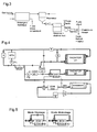
- the figure 1 illustrates the basic general concept of the present invention.
- the left part of the figure 1 shows schematically the assembly consisting of the engine and the intake gas circuit.
- the right part of the figure 1 shows schematically the air conditioning circuit.
- the invention involves on the one hand a transfer of mechanical energy between the motor assembly and the air conditioning circuit and on the other hand a transfer of thermal energy between the air conditioning circuit and the intake circuit.
- the coolant of the first and second cooling circuits is a conventional mixture of water and ethylene glycol with the addition of anti-corrosion agents.
- the air conditioning fluid is a conventional refrigerant (R134a, R152a, CO2 ).
- the air conditioning evaporators can be connected in series (the refrigerant being two-phase, its temperature does not vary).
- the thermostat T When the engine is warm, the thermostat T is open and the pump P1 circulates the coolant through the radiator HT.
- the recirculated gases (EGR) are pre-cooled by the HT circuit coolant (500 ° C -> 90 ° C) via the HT EGR. They are then subcooled in the LV circuit via the LV EGR.
- EGR recirculated gases
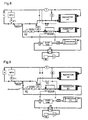
- the filling of the cold stock is illustrated in the Figures 4 and 5 :
- the P2 pump drives the coolant through the LV radiator and the bypass of the ECH STOCK storage exchanger.
- the recirculated gases are then cooled to a temperature close to the air entering the radiator BT.
- the liquid enclosed in the storage exchanger is undercooled by the air conditioning.
- the controlled valve V2 makes it possible to maintain a constant cold power in the passenger compartment evaporator (thus not to degrade comfort performance) by controlling the flow of refrigerant.
- V1 is a continuous valve, it is then possible to control the flow passing through the ECH STOCK heat exchanger and the flow passing through the bypass simultaneously in "continuous cooling" mode.
- the mixing of the two flow rates at the outlet makes it possible to obtain a continuous cooling of the liquid leaving the radiator BT and to control the temperature of the circulated gases.
- valve V1 can be an on-off valve. It is then sufficient to pass the entire flow in the storage exchanger. In this case, the temperature of the circulated gases will be controlled by regulating the flow rate of the pump P2.
- thermal regenerative braking is to convert the kinetic energy into cooling energy (or heat in the case of a heat pump) during the braking phases. During these phases, part of the kinetic energy normally dissipated in the brakes is then used to operate the air conditioning at its maximum capacity. Concretely, this will result in a control of the cubic capacity for a mechanical compressor, electronics for an electric compressor. The control of the compressor displacement makes it possible to increase or reduce the refrigerant mass flow rate, therefore the power taken from the evaporator.
- the wheels of the vehicle then convert the kinetic energy of advance of the vehicle into mechanical energy of rotation of the crankshaft.
- the timing belt driven by the latter makes it possible to transfer power to the air conditioning compressor.
- the latter converts the mechanical power of rotation into hydraulic power (flow and refrigerant pressure in the gas phase) causing a warming of the working fluid.
- the latter is cooled by the condenser whose cold source is ambient air and then expanded through a pressure reducer.
- the fluid thus obtained at low pressure and low temperature evaporates through a brine / refrigerant exchanger, causing a drop in the temperature of the latter.
- the system has converted kinetic energy into cooling energy.
- the fluid of the air conditioning loop cools the heat transfer liquid in the storage heat exchanger.
- the regenerative braking thermal allows to create a reusable energy stock later.
- This method also reduces the stress on the brakes and increases the life of the brakes.
- the circulating gas flow increases sharply and rapidly, causing a significant increase in the thermal power to be evacuated to maintain a constant temperature.
- the pilot valve V1 opens.
- the valve V1 can be controlled in a closed loop thanks to two thermocouples positioned at the outlet of the storage exchanger (Th1) and the BT radiator (Th2). The closing of the valve then occurs when the temperatures of Th1 and Th2 are the same.
- valve V1 For a dynamic and economical gain, the control of the valve V1 can be realized thanks to a thermocouple coupled to the state reconstructor. For dynamic gain, control in phase advance can be performed on valve V1.
- the on-board computer sends information from the accelerator or brake pedal directly to the valve. It takes advantage of the gas transport time in the air supply circuit to anticipate its opening and reduce the effect of its response time and hydraulic response time.
- valve V2 makes it possible or not to operate the passenger compartment evaporator.
- the entire hydraulic circuit can also work for heat storage: the low temperature fluid then becomes a high temperature fluid (R134a from a heat pump for example).
- the Figures 8 and 9 illustrate the hydraulic circuit according to the mention coupled to a reversible air conditioning in heat pump:
- valve V3 is closed.
- V4 valve is in direct mode.
- the operation of the system is the same as that of the basic hydraulic circuit.
- valve 9 The operation of this assembly in heat-up and heat pump mode is illustrated by the figure 9 :
- the V4 valve is open.
- Valve V4 is in inverted mode.
- Valve V1 is in destocking mode.
- the dead branch between the HV and LV circuits, which was initially used only to impose the reference pressure in the 2 circuits becomes a pipe in itself.
- the storage exchanger receives the heat generated by the heat pump cycle. The water leaving the engine passes through the storage exchanger to be heated then feeds the oil exchanger, accelerating the temperature rise of the latter.
- This architecture reduces the viscosity of the oil, reducing crankshaft friction and improving engine performance.
- P2 pump can be stopped to minimize power consumption. It can be in operation to improve the efficiency of the storage exchanger. In hot climate, this architecture can be used exclusively for the engine temperature rise with a very high heat pump efficiency and therefore a very low associated overconsumption.
- the heat pump also supplies the heater and heats the passenger compartment in addition to the passenger compartment condenser.
- the evaporator PAC is located in front of the radiator ST.
- the air leaving the evaporator has been cooled and attacks the radiator ST filled with static water.
- the latter then becomes a cold stock that can be used from the beginning of the cooling phases, thus leaving a delay when switching to cooling mode to cool the storage exchanger.
- recuperative braking by the air conditioning can also be used for the thermal interior.
- cold storage can be performed by accumulation of liquid water.
- the principle is to condense the water contained in the intake gas (EGR branch or collector), store it in a tank and inject it into a fluid to cool.
- a valve (electric or mechanical) between the separator and the tank makes it possible to regulate the level of water in the separator and to avoid any problem of gas leakage towards the tank.
- a calibrated purge valve makes it possible to evacuate the liquid water from the reservoir in case of overfilling.
- the injection of water is carried out in particular during upward transient conditions of the engine:
- a pump pressurizes the liquid water whose flow rate is regulated by an injector.
- All 3-way valves can be replaced by 2 single-way valves on each hydraulic branch.
- the cold storage is in the refrigerant / water heat exchanger.
- the storage is done in an additional volume placed at the outlet of the refrigerant / water heat exchanger, in a volume placed in the branch bypass.
Abstract
Description
La présente invention concerne le domaine des moteurs de véhicules automobiles fonctionnant au diesel ou à l'essence, comprenant un circuit de gaz d'échappement recirculés.The present invention relates to the field of motor vehicle engines operating on diesel or gasoline, comprising a recirculated exhaust gas circuit.
Les contraintes environnementales relatives aux émissions de gaz d'échappement d'un véhicule à moteur à combustion interne, notamment un moteur de type diesel, sont de plus en plus nombreuses. Les futures normes d'émissions polluantes nécessitent l'utilisation de systèmes de post-traitement coûteux, notamment pour diminuer les émissions d'oxydes d'azote (NOx). Une diminution de la température des gaz d'admission réduit les émissions de NOx et permet donc de s'affranchir de certains systèmes de post-traitement ou du moins de diminuer leur chargement en catalyseur et par conséquent le surcoût dû au post-traitement.The environmental constraints relating to the exhaust emissions of a vehicle with an internal combustion engine, in particular a diesel engine, are becoming more numerous. Future emissions standards require the use of expensive after-treatment systems, particularly to reduce nitrogen oxide (NOx) emissions. A decrease in the temperature of the inlet gases reduces the NOx emissions and thus makes it possible to overcome certain post-treatment systems or at least reduce their catalyst loading and therefore the additional cost due to post-treatment.
Actuellement, le refroidissement des gaz d'admission, c'est-à-dire un mélange d'air frais + gaz d'échappement recirculés, est souvent assuré par un radiateur en face avant du véhicule et/ou un échangeur dont la source froide est le liquide de refroidissement du moteur thermique.Currently, the cooling of the intake gases, that is to say a mixture of fresh air + recirculated exhaust gas, is often provided by a radiator on the front of the vehicle and / or an exchanger whose cold source is the coolant of the engine.
Il est également possible d'utiliser un circuit de refroidissement supplémentaire dédié dans le but d'obtenir des températures plus basses.
Le document
L'objectif de l'invention présentée ici est de réduire la température des gaz d'admission en utilisant la boucle de climatisation, sans entraîner de surconsommation moteur.The purpose of the invention presented here is to reduce the temperature of the intake gas using the air conditioning loop, without causing overconsumption engine.
L'invention propose des stratégies de pilotage variant en fonction des conditions de conduite du véhicule ainsi que des circuits hydrauliques associés.The invention proposes steering strategies that vary according to the driving conditions of the vehicle as well as the associated hydraulic circuits.
A cet effet, l'invention propose un véhicule automobile comprenant
- un moteur thermique comprenant un circuit de gaz d'échapement recirculés, le dit circuit de gaz recirculés comprenant un échangeur thermique pour les dits gaz d'échappement recirculés comprenant un premier étage haute température et un deuxième étage basse température,
- un premier circuit hydraulique de refroidissement du dit moteur,
- un circuit de climatisation de l'habitacle du véhicule comprenant, dans une première branche, un évaporateur dans lequel circule un fluide frigorigène,
- un deuxième circuit hydraulique de refroidissement des gaz recirculés, comprenant une pompe entraînant le liquide de refroidissement du dit deuxième circuit hydraulique,
ledit premier étage haute température étant disposé dans le premier circuit hydraulique de refroidissement et le dit deuxième étage basse température étant disposé dans le deuxième circuit hydraulique de refroidissement,
le dit véhicule comprenant
un échangeur thermique de stockage permettant un échange thermique entre le liquide de refroidissement du deuxième circuit hydraulique et le fluide frigorigène du circuit de climatisation,
le deuxième circuit hydraulique comprenant un dispositif de by-pass permettant au liquide de refroidissement du deuxième circuit hydraulique de by-passer l'échangeur thermique de stockage,
le circuit de climatisation comprenant une deuxième branche, en parallèle de la dite première branche de l'évaporateur, permettant aux fluide frigorigène de circuler dans l'échangeur thermique de stockage.
- a heat engine comprising a recirculated exhaust gas circuit, said recirculated gas circuit comprising a heat exchanger for said recirculated exhaust gas comprising a first high temperature stage and a second low temperature stage,
- a first hydraulic cooling circuit of said engine,
- an air conditioning circuit of the passenger compartment of the vehicle comprising, in a first branch, an evaporator in which circulates a refrigerant,
- a second hydraulic circuit for cooling the recirculated gases, comprising a pump driving the cooling liquid of said second hydraulic circuit,
said first high temperature stage being disposed in the first hydraulic cooling circuit and said second low temperature stage being disposed in the second hydraulic cooling circuit,
the said vehicle comprising
a storage heat exchanger allowing a heat exchange between the coolant of the second hydraulic circuit and the refrigerant of the air conditioning circuit,
the second hydraulic circuit comprising a bypass device allowing the cooling liquid of the second hydraulic circuit to bypass the storage heat exchanger,
the air conditioning circuit comprising a second branch, in parallel with said first branch of the evaporator, allowing the refrigerant to circulate in the storage heat exchanger.
Les gaz d'échappement recirculés peuvent être pris en amont de la turbine (EGR Haute Pression) ou en aval des systèmes de post-traitement (EGR Basse Pression).The recirculated exhaust gas can be taken upstream of the turbine (High Pressure EGR) or downstream of the aftertreatment systems (Low Pressure EGR).
Le dispositif de by-pass du deuxième circuit hydraulique de refroidissement peut comporter une vanne à trois voies.The bypass device of the second hydraulic cooling circuit may comprise a three-way valve.
Le deuxième circuit hydraulique de refroidissement peut comporter un radiateur pour refroidir son liquide de refroidissement.The second hydraulic cooling circuit may include a radiator for cooling its coolant.
Le circuit de climatisation peut comporter une vanne à trois voies permettant de faire passer le fluide frigorigène dans la première branche ou dans la deuxième branche.The air conditioning circuit may comprise a three-way valve for passing the refrigerant into the first branch or the second branch.
Le circuit de gaz d'échappement recirculés peut comporter en aval de l'échangeur thermique un séparateur de phases, un réservoir de liquide et un dispositif d'injection capable de réinjecter le dit liquide dans le circuit de gaz recirculés, en sortie de RAS, au niveau du collecteur d'admission ou directement dans la chambre de combustion. Lorsque le liquide est injecté dans le gaz, il s'évapore entraînant ainsi une diminution de la température du gaz.The recirculated exhaust gas circuit may comprise, downstream of the heat exchanger, a phase separator, a liquid reservoir and an injection device capable of reinjecting said liquid into the recirculated gas circuit, at the outlet of the RAS, at the intake manifold or directly into the combustion chamber. When the liquid is injected into the gas, it evaporates causing a decrease in the temperature of the gas.
Le circuit de climatisation peut être un circuit réversible en pompe à chaleur et comporter une vanne permettant d'inverser le débit du fluide , une vanne supplémentaire reliant la sortie du moteur thermique à la sortie du radiateur du deuxième circuit hydraulique.The air conditioning circuit can be a heat pump reversible circuit and include a valve for reversing the flow of the fluid, an additional valve connecting the output of the heat engine to the radiator output of the second hydraulic circuit.
Le dispositif selon l'invention est mis en oeuvre en régime de fonctionnement continu du moteur thermique du véhicule en pilotant la cylindrée ou la vitesse de rotation du compresseur du circuit de climatisation de façon à optimiser le rapport entre le gain moteur par remplissage et la consommation.The device according to the invention is implemented in the continuous operating mode of the engine of the vehicle by controlling the displacement or the speed of rotation of the compressor of the fuel circuit. air conditioning so as to optimize the ratio between the engine gain per filling and consumption.
On sait que lorsque le compresseur d'un système de climatisation d'un véhicule automobile fonctionne, il prélève de la puissance à l'arbre moteur, via la courroie accessoire si le compresseur est mécanique, via l'alternateur s'il est électrique. Par contre, un refroidissement des gaz d'admission entraîne une augmentation de la puissance délivrée par le moteur. En effet, la masse volumique des gaz d'admission augmente lorsque leur température diminue. Ainsi, à volume égal des cylindres, la masse d'air admise est plus grande, ce qui augmente la puissance: ce phénomène est qualifié de gain moteur par remplissage.It is known that when the compressor of an air conditioning system of a motor vehicle is operating, it draws power from the motor shaft, via the accessory belt if the compressor is mechanical, via the alternator if it is electric. On the other hand, a cooling of the intake gases causes an increase in the power delivered by the engine. Indeed, the density of the inlet gases increases when their temperature decreases. Thus, at equal volume of the cylinders, the air mass admitted is greater, which increases the power: this phenomenon is called engine gain by filling.
La présente invention met en oeuvre le fluide de climatisation du véhicule pour refroidir le liquide de refroidissement du circuit hydraulique mentionné ci-dessus, qui à son tour refroidit les gaz d'échappement recirculés, augmentant ainsi le gain moteur par remplissage. Il existe, sur un grand nombre de points moteur, un optimum permettant de générer un gain moteur par remplissage égal ou supérieur à la puissance consommée par le compresseur de climatisation. Le principe du pilotage continu consiste à adapter la cylindrée du compresseur, s'il est mécanique, ou sa vitesse de rotation, s'il est électrique, pour, au minimum, équilibrer le bilan.The present invention uses the vehicle air conditioning fluid to cool the coolant of the above-mentioned hydraulic circuit, which in turn cools the recirculated exhaust gas, thereby increasing the engine gain by refilling. There is, on a large number of motor points, an optimum for generating a motor gain by filling equal to or greater than the power consumed by the air conditioning compressor. The principle of continuous control is to adapt the compressor capacity, if it is mechanical, or its rotation speed, if it is electric, to at least balance the balance.
Lorsqu'il y a équilibre entre le gain par remplissage et la consommation du compresseur, le vilebrequin délivre la même puissance mécanique à la boite de vitesse que si la climatisation était éteinte, mais présente une température d'admission inférieure: Il y a par conséquent un gain en dépollution NOx ou NOX/particules et en durée de vie du piège à NOx ou Nox-trap.When there is a balance between the gain per fill and the consumption of the compressor, the crankshaft delivers the same mechanical power to the gearbox that if the air conditioning was off, but has a lower intake temperature: There is consequently a gain in NOx or NOX / particle pollution control and in lifetime of the NOx or NOx-Trap trap.
Lorsque le gain par remplissage est plus élevé que la consommation du compresseur, deux options sont possibles:
- Modifier les paramètres de fonctionnement du moteur pour réduire sa consommation.
- Accumuler et stocker du froid supplémentaire pour l'utiliser, par exemple, lorsque l'équilibre remplissage/compresseur n'est pas possible.
- Change engine operating parameters to reduce fuel consumption.
- Accumulate and store extra cold to use, for example, when the balance filling / compressor is not possible.
Ce pilotage en régime continu permet d'équilibrer le bilan mécanique entre la consommation supplémentaire due au compresseur et le gain moteur par remplissage.This continuous-speed control makes it possible to balance the mechanical balance between the additional consumption due to the compressor and the engine gain by filling.
Lorsque le gain moteur par remplissage est supérieur à la consommation supplémentaire du compresseur, le dispositif selon l'invention peut être mis en oeuvre en régime continu en faisant circuler le liquide de refroidissement du deuxième circuit hydraulique dans le by-pass de l'échangeur thermique de stockage de façon à stocker du froid dans le dit échangeur thermique de stockage. Cet échangeur doit être calorifugé pour diminuer les pertes thermiques avec l'environnement chaud sous capot.When the engine gain by filling is greater than the additional consumption of the compressor, the device according to the invention can be implemented in a continuous mode by circulating the cooling liquid of the second hydraulic circuit in the bypass of the heat exchanger. storage so as to store cold in said storage heat exchanger. This exchanger must be insulated to reduce heat loss with the hot environment under hood.
Lorsque le gain moteur par remplissage est supérieur à la consommation supplémentaire du compresseur, le dispositif selon l'invention peut être mis en oeuvre en régime continu en condensant partiellement les gaz recirculés dans le deuxième étage basse température de l'échangeur thermique des gaz d'échappement,c'est-à-dire en condensant de la vapeur d'eau, en séparant la phase liquide des gaz et en stockant ladite phase liquide. Le stockage de cette eau liquide équivaut à une accumulation de frigories.When the engine gain by filling is greater than the additional consumption of the compressor, the device according to the invention can be implemented in continuous mode by partially condensing the recirculated gases in the second low temperature stage of the gas heat exchanger. exhaust, that is to say by condensing water vapor, separating the liquid phase of the gases and storing said liquid phase. The storage of this liquid water is equivalent to an accumulation of frigories.
Le dispositif selon l'invention est mis en oeuvre en régime transitoire du moteur thermique pendant les freinages du véhicule en maximisant la cylindrée ou la vitesse de rotation du compresseur du circuit de climatisation et en faisant circuler le liquide de refroidissement du deuxième circuit hydraulique dans le by-pass de l'échangeur thermique de stockage de façon à accumuler du froid dans le dit l'échangeur thermique de stockage.The device according to the invention is implemented in the transient state of the engine during the braking of the vehicle by maximizing the displacement or the rotation speed of the compressor of the air conditioning circuit and by circulating the coolant of the second hydraulic circuit in the bypass of the heat exchanger of storage so as to accumulate cold in said storage heat exchanger.
Durant cette phase, le compresseur de climatisation entraîné par le vilebrequin via la courroie d'accessoires renvoie un couple résistant (énergie mécanique) permettant de ralentir la vitesse de rotation du vilebrequin donc de freiner. Le principe du pilotage capacitif consiste donc à stocker du froid dans un composant calorifugé par freinage récupératif avec le compresseur de climatisation, puis vider ce stock lors de phases transitoires pour lesquelles le pilotage continu n'est pas suffisant ou lorsque les sollicitations thermiques sont trop importantes.During this phase, the air conditioning compressor driven by the crankshaft via the accessory belt returns a resistant torque (mechanical energy) to slow the speed of rotation of the crankshaft thus to brake. The principle of capacitive control therefore consists in storing cold in a heat-insulated component by regenerative braking with the air-conditioning compressor, then emptying this stock during transient phases for which continuous control is not sufficient or when the thermal stresses are too important. .
Le froid accumulé lors du pilotage continu ou d'un freinage récupératif est déstocké quand l'équilibre gain moteur par remplissage/compresseur n'est pas possible ou lors d'un transitoire ascendant impliquant des sollicitations thermiques importantes, donc des émissions de NOx élevées.The accumulated cold during the continuous piloting or regenerative braking is destocked when the engine gain balance by filling / compressor is not possible or during an ascending transient involving significant thermal stresses, thus high NOx emissions.
Le dispositif selon l'invention peut être mis en oeuvre en régime transitoire du moteur thermique pendant les accélérations du véhicule en fermant le by-pass de l'échangeur thermique de stockage et en faisant circuler le liquide de refroidissement du deuxième circuit hydraulique dans l'échangeur thermique de stockage de façon à expulser le liquide froid du dit échangeur thermique de stockage.The device according to the invention can be implemented in the transient state of the engine during accelerations of the vehicle by closing the bypass of the storage heat exchanger and by circulating the coolant of the second hydraulic circuit in the heat exchanger storage so as to expel the cold liquid from said storage heat exchanger.
En fonctionnement nominal, le liquide de refroidissement, caloporteur (eau glycolée par exemple), circule dans le by-pass de l'échangeur de stockage pour aller refroidir un ou plusieurs composants en aval, un RAS ou un EGR par exemple, et réguler la température de fluides chauds, alors qu'une certaine masse de liquide caloporteur, non circulante, accumule des frigories dans l'échangeur de stockage.In nominal operation, the coolant, coolant (brine, for example), circulates in the bypass of the storage exchanger to cool one or more downstream components, such as a RAS or an EGR, and regulate the temperature of hot fluids, while a certain mass of coolant, non-circulating, accumulates frigories in the storage exchanger.
Lorsque le stock de frigories doit être entièrement ou partiellement vidé, la vanne 3 voies pilotée s'ouvre. Le liquide stocké sous-refroidi est alors poussé par le flux de liquide caloporteur, et traverse l'échangeur thermique. Lorsque le transitoire est terminé, la vanne 3 voies se referme, et le stock se recharge.When the cold store must be completely or partially emptied, the piloted 3-way valve opens. The liquid stored undercooled is then pushed by the coolant flow, and passes through the exchanger thermal. When the transient is complete, the 3-way valve closes, and the stock recharges.
Le temps de réponse de ce système est égal au volume de l'échangeur thermique divisé par le débit de fluide caloporteur plus le temps de réponse de la vanne. Ce temps de réponse est beaucoup plus faible que pour un système conventionnel avec les inerties thermiques des organes suivants: radiateur, pompe hydraulique, échangeur. On peut donc qualifier ce phénomène de déstockage thermique instantané.The response time of this system is equal to the volume of the heat exchanger divided by the coolant flow rate plus the response time of the valve. This response time is much lower than for a conventional system with the thermal inertia of the following organs: radiator, hydraulic pump, exchanger. We can therefore qualify this phenomenon of instant thermal destocking.
Dans le cadre de l'invention revendiquée, le cycle énergétique moteur/climatisation fonctionne donc comme un système moteur/batterie dans le cas d'un véhicule hybride électrique. On peut donc qualifier ce fonctionnement par le terme d'hybridation thermique.In the context of the claimed invention, the engine / air-conditioning energy cycle thus functions as a motor / battery system in the case of an electric hybrid vehicle. We can therefore qualify this operation by the term thermal hybridization.
L'invention sera mieux comprise de l'homme du métier grâce à la description détaillée ci-dessous de certains modes d'exécution et des figures accompagnantes, dans lesquelles
- la
figure 1 est un schéma de principe illustrant le pilotage du dispositif selon l'invention en mode de fonctionnement continu, - la
figure 2 est un schéma de principe illustrant le fonctionnement de l'échangeur thermique de stockage, - la
figure 3 est un schéma de principe illustrant la condensation partielle des gaz et le stockage de froid sous forme d'eau liquide, - la
figure 4 est un schéma de principe illustrant un premier mode d'exécution du circuit hydraulique selon l'invention, en mode refroidissement, - la
figure 5 est un schéma de principe illustrant les modes de fonctionnement de l'échangeur thermique de stockage, - la
figure 6 est un schéma de principe illustrant le circuit hydraulique de lafigure 4 en mode montée en température du moteur, - la
figure 7 est un schéma de principe illustrant un deuxième mode d'exécution du circuit hydraulique selon l'invention, - la
figure 8 est un schéma de principe illustrant un troisième mode d'exécution du circuit hydraulique selon l'invention, en mode refroidissement, et - la
figure 9 est un schéma de principe illustrant le circuit hydraulique de la figure huit en mode de montée en température.
- the
figure 1 is a block diagram illustrating the control of the device according to the invention in continuous operation mode, - the
figure 2 is a block diagram illustrating the operation of the storage heat exchanger, - the
figure 3 is a schematic diagram illustrating the partial condensation of gases and the storage of cold in the form of liquid water, - the
figure 4 is a block diagram illustrating a first embodiment of the hydraulic circuit according to the invention, in cooling mode, - the
figure 5 is a block diagram illustrating the operating modes of the storage heat exchanger, - the
figure 6 is a schematic diagram illustrating the hydraulic circuit of thefigure 4 in engine temperature rise mode, - the
figure 7 is a block diagram illustrating a second embodiment of the hydraulic circuit according to the invention, - the
figure 8 is a block diagram illustrating a third embodiment of the hydraulic circuit according to the invention, in cooling mode, and - the
figure 9 is a block diagram illustrating the hydraulic circuit of Figure eight in temperature rise mode.
La
Le système hydraulique de base, illustré dans la
- un premier circuit haute température et son radiateur HT,
- un deuxième circuit basse température et son radiateur BT,
- un circuit de climatisation et son condenseur (CLIM).
- a first high temperature circuit and its HT radiator,
- a second low temperature circuit and its BT radiator,
- an air conditioning circuit and its condenser (CLIM).
Le montage aéraulique des radiateurs et des condenseurs en face avant du véhicule peut se présenter comme suit:
- Condenseur devant radiateur BT devant radiateur HT.
- Condenseur devant radiateur BT sous radiateur HT.
- Radiateur BT devant condenseur devant radiateur HT
- Radiateur BT sous condenseur devant radiateur HT
- Condenser in front of radiator BT in front of radiator HT.
- Condenser in front of radiator BT under radiator HT.
- BT radiator in front of condenser in front of radiator HT
- BT radiator under condenser in front of radiator HT
Le premier circuit de refroidissement est composé d'organes conventionnels:
- un moteur thermique: MTH,
- un aérotherme : A,
- une pompe à eau mécanique P1 entraînée par le moteur thermique (on peut aussi envisager l'utilisation d'une pompe à eau électrique),
- un bocal de dégazage: B,
- un thermostat principal: T,
- un refroidisseur d'huile moteur MOD
- a heat engine: MTH,
- a heater: A,
- a mechanical water pump P1 driven by the heat engine (one can also consider the use of an electric water pump),
- a degassing jar: B,
- a main thermostat: T,
- a MOD engine oil cooler
Le deuxième circuit de refroidissement selon l'invention comprend:
- une pompe électrique P2,
- un échangeur EGR de gaz d'échappement recirculés à deux étages(EGR HT et EGR BT) comportant 2 entrées et 2 sorties pour le liquide de refroidissement, avec une entrée et une sortie de gaz d'échappement recirculés,
- un échangeur liquide de refroidissement / fluide frigorigène (ECH STOCK) .
une vanne 3 voies V1
- an electric pump P2,
- a two-stage recirculated exhaust gas EGR exchanger (EGR HT and EGR BT) having two inlets and two outlets for the coolant, with a recirculated exhaust gas inlet and outlet,
- a coolant / refrigerant exchanger (ECH STOCK).
- a 3-way valve V1
Le circuit de climatisation est composé des organes conventionnels suivants:
- un compresseur C, soit mécanique à cylindrée fixe (fonctionnement et arrêt en alternance), soit mécanique à cylindrée pilotée, soit hybride, soit électrique; ces compresseurs permettent d'ajuster la production de frigories en fonction de la demande, c'est-à-dire pour le refroidissement de l'habitacle et pour le refroidissement des gaz d'échappement recirculés.
- un condenseur,
- un réservoir / séparateur S .
- un détendeur D commun aux deux branches ou un détendeur dans chaque branche,
- un évaporateur (EVAP HAB).
- a compressor C, either mechanical fixed displacement (running and stopping alternately), or mechanical controlled displacement, hybrid or electric; these compressors make it possible to adjust the production of frigories according to the demand, that is to say for the cooling of the passenger compartment and for the cooling of the recirculated exhaust gases.
- a condenser,
- a tank / separator S.
- a regulator D common to both branches or a regulator in each branch,
- an evaporator (EVAP HAB).
Le circuit de climatisation, comprend également, selon l'invention:
- une branche en parallèle de l'évaporateur traversant l'échangeur fluide frigorigène / liquide ECH STOCK,
- une vanne à trois voies pilotée V2,
- a parallel branch of the evaporator passing through the ECH STOCK refrigerant / liquid exchanger,
- a three-way piloted valve V2,
Le liquide de refroidissement du premier et du deuxième circuit de refroidissement est un mélange conventionnel d'eau et d'éthylène glycol avec un ajout d'agents anti-corrosion. Le fluide de la climatisation est un fluide frigorigène conventionnel (R134a, R152a, CO2 ...).The coolant of the first and second cooling circuits is a conventional mixture of water and ethylene glycol with the addition of anti-corrosion agents. The air conditioning fluid is a conventional refrigerant (R134a, R152a, CO2 ...).
Les évaporateurs de climatisation peuvent être branchés en série (le fluide frigorigène étant diphasique, sa température ne varie pas).The air conditioning evaporators can be connected in series (the refrigerant being two-phase, its temperature does not vary).
Lorsque le moteur est chaud, le thermostat T est ouvert et la pompe P1 fait circuler le liquide de refroidissement à travers le radiateur HT. Les gaz recirculés (EGR) sont pré refroidis par le liquide de refroidissement du circuit HT ( 500°C -> 90°C) via l'EGR HT. Ils sont ensuite sous-refroidis dans le circuit BT via l'EGR BT. Cette configuration permet un gain en compacité des échangeurs et une utilisation optimale de la valise de refroidissement constituée de l'ensemble radiateur HT et BT.When the engine is warm, the thermostat T is open and the pump P1 circulates the coolant through the radiator HT. The recirculated gases (EGR) are pre-cooled by the HT circuit coolant (500 ° C -> 90 ° C) via the HT EGR. They are then subcooled in the LV circuit via the LV EGR. This configuration allows a gain in compactness of the exchangers and optimal use of the cooling case consisting of the HT and BT radiator assembly.
Le remplissage du stock de froid est illustré dans les
L'énergie nécessaire au compresseur de climatisation C peut être récupérée durant:
- les phases de freinage du véhicule ou de décélération, comme décrit plus en détail ci-dessous.
- les phases de roulage stabilisé par pilotage du couple rendement moteur / COP de climatisation via le calculateur embarqué. En effet, les rendements du moteur et de la climatisation sont directement liés à leur régime et couple respectifs, chacune d'elle passant par un rendement maximal à régime donné. Par une loi d'optimisation, le calculateur pourra définir les couples optimaux des 2 systèmes permettant de minimiser la consommation de carburant.
- the vehicle braking or deceleration phases, as described in more detail below.
- stabilized taxiing phases by controlling the engine output / COP air conditioning torque via the on-board computer. In fact, the engine and air conditioning efficiencies are directly related to their respective speed and torque, each of which passes through a maximum efficiency at a given speed. By a law of optimization, the calculator will be able to define the optimal couples of the 2 systems making it possible to minimize the fuel consumption.
Dans les deux cas, la vanne pilotée V2 permet de maintenir une puissance de froid constante dans l'évaporateur habitacle (donc de ne pas dégrader la prestation confort) par pilotage du débit de réfrigérant.In both cases, the controlled valve V2 makes it possible to maintain a constant cold power in the passenger compartment evaporator (thus not to degrade comfort performance) by controlling the flow of refrigerant.
Si V1 est une vanne continue, il est alors possible de piloter le débit passant dans l'échangeur ECH STOCK et le débit passant dans le by-pass simultanément en mode « sous refroidissement continu ». Le mélange des 2 débits en sortie permet d'obtenir un sous refroidissement continu du liquide sortant du radiateur BT et de piloter la température des gaz circulés.If V1 is a continuous valve, it is then possible to control the flow passing through the ECH STOCK heat exchanger and the flow passing through the bypass simultaneously in "continuous cooling" mode. The mixing of the two flow rates at the outlet makes it possible to obtain a continuous cooling of the liquid leaving the radiator BT and to control the temperature of the circulated gases.
Cette fonction peut aussi être réalisée par une vanne tout ou rien. Dans les deux cas cités ci-dessus, la vanne V1 peut être une vanne tout ou rien. Il suffit alors de faire passer l'intégralité du débit dans l'échangeur de stockage. Dans ce cas, le pilotage de la température des gaz circulés sera réalisé par régulation du débit de la pompe P2.This function can also be performed by an all or nothing valve. In both cases mentioned above, the valve V1 can be an on-off valve. It is then sufficient to pass the entire flow in the storage exchanger. In this case, the temperature of the circulated gases will be controlled by regulating the flow rate of the pump P2.
Les échanges thermiques entre le liquide de refroidissement et le fluide de climatisation pendant les phases de pilotage capacitif sur des transitoires sont illustrés sur la
Lorsque un véhicule freine, son énergie cinétique est en partie dissipée au niveau des freins. Sur certains véhicules, une partie de cette énergie est convertie en énergie électrique. Il s'agit de décharger les freins en sollicitant l'alternateur lors des freinages (stop and START, freinage hybride électrique, alternateur piloté, freinage récupératif...).When a vehicle brakes, its kinetic energy is partly dissipated at the brakes. On some vehicles, some of this energy is converted into electrical energy. This involves unloading the brakes by using the alternator during braking (stop and start, hybrid electric braking, controlled alternator, regenerative braking ...).
Le principe de freinage récupératif thermique est de convertir l'énergie cinétique en énergie frigorifique (ou calorifique dans le cas d'une pompe à chaleur) lors des phases de freinage. Lors de ces phases, une partie de l'énergie cinétique normalement dissipée dans les freins est alors utilisée pour faire fonctionner la climatisation à sa capacité maximale. Concrètement, cela se traduira par un pilotage de la cylindrée pour un compresseur mécanique, de l'électronique pour un compresseur électrique. Le pilotage de la cylindrée compresseur permet d'augmenter ou réduire le débit massique de réfrigérant, donc la puissance prélevée dans l'évaporateur.The principle of thermal regenerative braking is to convert the kinetic energy into cooling energy (or heat in the case of a heat pump) during the braking phases. During these phases, part of the kinetic energy normally dissipated in the brakes is then used to operate the air conditioning at its maximum capacity. Concretely, this will result in a control of the cubic capacity for a mechanical compressor, electronics for an electric compressor. The control of the compressor displacement makes it possible to increase or reduce the refrigerant mass flow rate, therefore the power taken from the evaporator.
Les roues du véhicule convertissent alors l'énergie cinétique d'avancement du véhicule en énergie mécanique de rotation du vilebrequin. La courroie de distribution entraînée par ce dernier permet de transférer la puissance vers le compresseur de climatisation. Ce dernier convertit la puissance mécanique de rotation en puissance hydraulique (débit et pression de réfrigérant en phase gazeuse) provoquant un réchauffement du fluide de travail. Ce dernier est refroidi par le condenseur dont la source froide est l'air ambiant, puis détendu à travers un détendeur. Le fluide ainsi obtenu à basse pression et basse température s'évapore à travers un échangeur eau glycolée/réfrigérant, provoquant une baisse de la température de ce dernier. Le système a ainsi converti une énergie cinétique en énergie frigorifique. Durant cette phase, le fluide de la boucle de climatisation refroidit le liquide caloporteur dans l'échangeur thermique de stockage. Le freinage récupératif thermique permet donc de créer un stock d'énergie réutilisable ultérieurement.The wheels of the vehicle then convert the kinetic energy of advance of the vehicle into mechanical energy of rotation of the crankshaft. The timing belt driven by the latter makes it possible to transfer power to the air conditioning compressor. The latter converts the mechanical power of rotation into hydraulic power (flow and refrigerant pressure in the gas phase) causing a warming of the working fluid. The latter is cooled by the condenser whose cold source is ambient air and then expanded through a pressure reducer. The fluid thus obtained at low pressure and low temperature evaporates through a brine / refrigerant exchanger, causing a drop in the temperature of the latter. The system has converted kinetic energy into cooling energy. During this phase, the fluid of the air conditioning loop cools the heat transfer liquid in the storage heat exchanger. The regenerative braking thermal allows to create a reusable energy stock later.
Cette méthode permet de plus de réduire la sollicitation des freins et d'en augmenter la durée de vie.This method also reduces the stress on the brakes and increases the life of the brakes.
Lors d'une accélération du véhicule, le débit de gaz circulés augmente fortement et rapidement, provoquant une augmentation importante de la puissance thermique à évacuer pour maintenir une température constante. Durant cette phase, la vanne pilotée V1 s'ouvre.During an acceleration of the vehicle, the circulating gas flow increases sharply and rapidly, causing a significant increase in the thermal power to be evacuated to maintain a constant temperature. During this phase, the pilot valve V1 opens.
Le débit dans le by-pass devient nul et le liquide froid enfermé dans l'échangeur de stockage est 'poussé' dans l'échangeur EGR BT. La conséquence est une baisse instantanée de la température du liquide de refroidissement à débit constant. Ce pilotage permet de minimiser, voire annuler l'augmentation de température des gaz EGR durant le transitoire. L'impact est un gain sur les émissions de NOx du moteur et donc la durée de vie du piège à NOx ou Nox-trap, et sa consommation de carburant.The flow in the bypass becomes zero and the cold liquid enclosed in the storage exchanger is 'pushed' into the EGR exchanger BT. The consequence is an instantaneous drop in the temperature of the constant flow coolant. This control makes it possible to minimize or even cancel the temperature increase of the EGR gases during the transient. The impact is a gain on NOx emissions from the engine and thus the lifetime of the NOx trap or Nox-trap, and its fuel consumption.
Le pilotage de la vanne V1 peut être réalisé en boucle fermée grâce à 2 thermocouples positionnés en sortie de l'échangeur (Th1) de stockage et du radiateur BT (Th2). La fermeture de la vanne intervient alors lorsque les températures de Th1 et Th2 sont les mêmes.The valve V1 can be controlled in a closed loop thanks to two thermocouples positioned at the outlet of the storage exchanger (Th1) and the BT radiator (Th2). The closing of the valve then occurs when the temperatures of Th1 and Th2 are the same.
Le pilotage de la vanne V1 peut être réalisé en boucle ouverte grâce à un reconstructeur d'état basé la connaissance du volume interne de l'échangeur, le temps de réponse de la vanne V1, la connaissance du régime (ou la tension) de la pompe P1, sa cartographie débit = f(perte de charge) et la caractéristique hydraulique du circuit BT (ou section équivalente). Le temps de déstockage peut alors être estimé par 
(avec TVI = Temps de réponse de la vanne V1). Le débit volumique est alors calculé par le modèle hydraulique de la boucle BT par résolution de l'équation 
dans le cas d'un circuit d'eau basse température séparé du circuit d'eau haute température.(with TVI = Response time of valve V1). The volume flow is then calculated by the hydraulic model of the LV loop by solving the equation
in the case of a low temperature water circuit separated from the high temperature water circuit.
Pour un gain dynamique et économique, le pilotage de la vanne V1 peut être réalisé grâce à un thermocouple couplé au reconstructeur d'état. Pour un gain dynamique, un pilotage en avance de phase peut être réalisé sur la vanne V1. Le calculateur embarqué envoie les informations provenant de la pédale d'accélération ou de frein directement à la vanne. Celle-ci profite du temps de transport des gaz dans le circuit d'alimentation d'air pour anticiper son ouverture et réduire l'effet de son temps de réponse et du temps de réponse hydraulique.For a dynamic and economical gain, the control of the valve V1 can be realized thanks to a thermocouple coupled to the state reconstructor. For dynamic gain, control in phase advance can be performed on valve V1. The on-board computer sends information from the accelerator or brake pedal directly to the valve. It takes advantage of the gas transport time in the air supply circuit to anticipate its opening and reduce the effect of its response time and hydraulic response time.
Lorsque le véhicule se trouve dans les conditions de régime spécifiques, le circuit hydraulique décrit ci-dessus s'adapte à des stratégies de pilotage particulières.When the vehicle is in the specific speed conditions, the hydraulic circuit described above adapts to particular steering strategies.
La
- pendant les premières minutes (by-pass EGR), il n'y a pas de recirculation des gaz d'échappement moteur ; les gaz recirculés ne sont pas refroidis pour favoriser la montée en température dans la chambre de combustion. Durant cette phase, la pompe électrique et le sous refroidissement continu ne sont pas activés. Par contre, le freinage récupératif avec la climatisation est activé et commence à accumuler du froid dans l'échangeur de stockage.
- Fin du by-pass EGR: Il y a recirculation des gaz d'échappement moteur. Ces derniers sont refroidis dans l'EGR HT et le pilotage capacitif est toujours activé. L'activation de la pompe électrique dépendra essentiellement de la température de la boucle HT en regard du gain en remplissage.
- during the first minutes (EGR bypass), there is no recirculation of the engine exhaust gases; the recirculated gases are not cooled to promote the rise in temperature in the combustion chamber. During this phase, the electric pump and the sub continuous cooling are not enabled. On the other hand, regenerative braking with air conditioning is activated and begins to accumulate cold in the storage exchanger.
- End of the EGR bypass: There is recirculation of the engine exhaust. These are cooled in the HT EGR and the capacitive control is always activated. The activation of the electric pump will depend essentially on the temperature of the HT loop with respect to the gain in filling.
Durant cette phase et suivant les conditions climatiques, la vanne V2 permet ou non de faire fonctionner l'évaporateur habitacle.During this phase and according to the climatic conditions, the valve V2 makes it possible or not to operate the passenger compartment evaporator.
L'ensemble du circuit hydraulique peut également fonctionner pour un stockage de chaleur : le fluide basse température devient alors un fluide haute température (du R134a provenant d'une pompe à chaleur par exemple). Les
Cette architecture implique l'intégration de 2 vannes pilotées supplémentaires:
- La vanne V3 reliant la sortie du moteur thermique à la sortie du radiateur ST.
- La vanne V4 permettant d'inverser le débit dans la boucle de climatisation. Cette inversion permet de transformer le condenseur de climatisation en évaporateur de la pompe à chaleur et les 2 évaporateurs de climatisation en 2 condenseurs de la pompe à chaleur.
- The valve V3 connecting the output of the engine to the output of the radiator ST.
- The valve V4 to reverse the flow in the air conditioning loop. This inversion makes it possible to transform the air conditioning condenser into an evaporator of the heat pump and the 2 air conditioning evaporators into 2 condensers of the heat pump.
Le fonctionnement de cet ensemble en mode refroidissement et climatisation est illustré par la
Le fonctionnement de cet ensemble en mode montée en température et pompe à chaleur est illustré par la
En climat froid, la pompe à chaleur alimente aussi l'aérotherme et permet de chauffer l'habitacle en complément du condenseur d'habitacle.In cold climates, the heat pump also supplies the heater and heats the passenger compartment in addition to the passenger compartment condenser.
Selon un mode d'exécution particulier, dans la valise de refroidissement, l'évaporateur de PAC est situé devant le radiateur ST. Dans ce cas, l'air sortant de l'évaporateur a été refroidi et attaque le radiateur ST rempli d'eau statique. Ce dernier devient alors un stock de froid utilisable dès le début des phases de refroidissement, laissant ainsi un délai lors du passage en mode climatisation pour refroidir l'échangeur de stockage.According to a particular embodiment, in the cooling bag, the evaporator PAC is located in front of the radiator ST. In this case, the air leaving the evaporator has been cooled and attacks the radiator ST filled with static water. The latter then becomes a cold stock that can be used from the beginning of the cooling phases, thus leaving a delay when switching to cooling mode to cool the storage exchanger.
Le freinage récupératif par la climatisation peut également être utilisé pour la thermique habitacle.The recuperative braking by the air conditioning can also be used for the thermal interior.
Selon un mode d'exécution particulier illustré par la
- Le radiateur BT est supprimé. La boucle basse température est intégralement refroidie par la climatisation. Cette solution permet le gain d'un radiateur, soit la possibilité d'augmenter la taille du condenseur et du radiateur HT ou la vitesse de l'air qui les traverse. Cette solution réduit l'inertie thermique de la boucle BT.
- The BT radiator is removed. The low temperature loop is completely cooled by the air conditioning. This solution allows the gain of a radiator, the possibility of increasing the size of the condenser and the radiator HT or the speed of the air passing through them. This solution reduces the thermal inertia of the LV loop.
Selon un mode d'exécution de la présente convention, illustré par la
En fonctionnement nominal, les gaz recirculés sont refroidis en dessous de leur température de saturation (#60°C) par de l'eau glycolée sous-refroidie ou un fluide de tel que le R 134a . Une partie de l'eau contenue dans les gaz se condense et est récupérée à l'aide d'un séparateur de phases. L'eau liquide prélevée est ensuite stockée dans un réservoir. Dans le cadre de la présente invention, les dispositifs de condensation et de récupération peuvent être positionnés:
- En sortie de l'échangeur EGR,
- En entrée du répartiteur d'admission.
- At the outlet of the EGR exchanger,
- Inlet inlet distributor.
Une vanne (électrique ou mécanique) entre le séparateur et le réservoir permet de réguler le niveau d'eau dans le séparateur et d'éviter tout problème de fuite de gaz vers le réservoir. Une vanne de purge tarée permet d'évacuer l'eau liquide du réservoir en cas de sur remplissage. L'injection de l'eau est effectuée en particulier lors de régime transitoires ascendants du moteur: Une pompe pressurise l'eau liquide dont le débit est régulé par un injecteur.A valve (electric or mechanical) between the separator and the tank makes it possible to regulate the level of water in the separator and to avoid any problem of gas leakage towards the tank. A calibrated purge valve makes it possible to evacuate the liquid water from the reservoir in case of overfilling. The injection of water is carried out in particular during upward transient conditions of the engine: A pump pressurizes the liquid water whose flow rate is regulated by an injector.
Dans le cas d'une application automobile, l'injecteur peut être positionné:
- Dans le répartiteur d'admission, en sortie RAS et/ou en sortie EGR : Il s'agit alors de piloter la température au collecteur par évaporation de l'eau liquide. En effet, l'eau liquide injectée dans les gaz d'admission prend de l'énergie aux gaz d'admission pour s'évaporer, ce qui entraîne une baisse de la température de ces derniers.
- Directement dans la chambre de combustion, ce qui implique l'intégration d'un injecteur d'eau
- En pré mélange avec le carburant avant l'injecteur.
- In the inlet manifold, RAS output and / or EGR output: It is then to control the temperature at the collector by evaporation of the liquid water. In fact, the liquid water injected into the intake gases takes the energy at the intake gases to evaporate, which leads to a decrease in the temperature of the latter.
- Directly in the combustion chamber, which implies the integration of a water injector
- In pre-mix with the fuel before the injector.
Il est également possible d'injecter l'eau liquide en amont d'un échangeur pour le décrasser afin qu'il conserve ces performances thermiques.It is also possible to inject the liquid water upstream of a heat exchanger to remove it so that it maintains these thermal performance.
Les circuits hydrauliques présentés ci-dessus sont tous applicables à la stratégie de stockage thermique sous forme d'eau liquide. Il suffit alors d'ajouter un séparateur en aval de l'échangeur basse température EGR BT pour récupérer le condensat.The hydraulic circuits presented above are all applicable to the thermal storage strategy in the form of liquid water. It is then sufficient to add a separator downstream of the low temperature exchanger EGR BT to recover the condensate.
De nombreuses variantes du circuit hydraulique peuvent être mises en oeuvre sans sortir du cadre de la présente invention :
- Dans la description ci-dessus, l'EGR BT est refroidi à basse ou très basse température. Cet échangeur peut être remplacé par:
- Un RAS basse température
- Un échangeur sur le répartiteur d'admission d'air
- Un RAS basse température en parallèle avec un EGR BT
- Un RAS normal en parallèle avec un EGR BT.
- In the above description, the BT EGR is cooled to low or very low temperature. This exchanger can be replaced by:
- Low temperature RAS
- An exchanger on the air intake manifold
- A low temperature RAS in parallel with an EGR BT
- Normal RAS in parallel with a BT EGR.
Toutes les vannes 3 voies peuvent être remplacées par 2 vannes mono voie sur chacune des branches hydrauliques.All 3-way valves can be replaced by 2 single-way valves on each hydraulic branch.
Dans l'ensemble de la description ci-dessus, le stockage de froid se fait dans l'échangeur fluide frigorigène/eau. Pour des raisons d'intégration dans le véhicule, il est également possible que le stockage se fasse dans un volume supplémentaire placé en sortie de l'échangeur fluide frigorigène/eau, dans un volume placé dans la branche bypass.Throughout the above description, the cold storage is in the refrigerant / water heat exchanger. For reasons of integration into the vehicle, it is also possible that the storage is done in an additional volume placed at the outlet of the refrigerant / water heat exchanger, in a volume placed in the branch bypass.
Claims (6)
- Motor vehicle comprising:- an internal combustion engine (MHT) comprising an exhaust gas recirculation circuit, said exhaust gas recirculation circuit comprising a heat exchanger for said recirculated exhaust gases (EGR HT, EGR BT), comprising a high-temperature first stage and a low-temperature second stage,- a first hydraulic circuit for cooling said engine (MHT),- a climate-control circuit for air-conditioning the cabin of the vehicle comprising, in a first leg, an evaporator (EVAP HAB) through which a refrigerant circulates,- a second hydraulic circuit for cooling the recirculated gases (EGR HT, EGR BT), comprising a pump (P2) driving the coolant of said second hydraulic circuit,
said high-temperature first stage being located in the first hydraulic cooling circuit and said low-temperature second stage being located in the second hydraulic cooling circuit,- a storage heat exchanger (ECH STOCK) allowing an exchange of heat between the coolant of the second hydraulic circuit and the refrigerant of the climate-control circuit,
the climate-control circuit comprises a second leg, in parallel with said first leg of the evaporator, allowing the refrigerant to circulate through the storage heat exchanger (ECH STOCK),
characterized in that
the second hydraulic circuit comprises a bypass device (V1) allowing the coolant of the second hydraulic circuit to bypass the storage heat exchanger (ECH STOCK). - Vehicle according to Claim 1, characterized in that the bypass device of the second hydraulic cooling circuit comprises a three-way valve (V1).
- Vehicle according to Claim 1 or 2, characterized in that the second hydraulic cooling circuit comprises a radiator (RADIATOT BT) for cooling its coolant.
- Vehicle according to one of the preceding claims, characterized in that the climate-control circuit comprises a three-way valve (V2) allowing the refrigerant to enter either the first leg or the second leg.
- Vehicle according to one of the preceding claims, characterized in that the exhaust gas recirculation circuit comprises, downstream of the heat exchanger (ECH STOCK), a phase separator, a liquid reservoir and an injection device capable of reinjecting said liquid into the EGR circuit.
- Vehicle according to one of the preceding claims, characterized in that the climate-control circuit is a reversible heat pump circuit and comprises a valve (V4) for reversing the flow of the fluid, an additional valve connecting the outlet from the combustion engine to the outlet from the radiator of the second hydraulic circuit.
Applications Claiming Priority (2)
| Application Number | Priority Date | Filing Date | Title |
|---|---|---|---|
| FR0708497A FR2924756A1 (en) | 2007-12-05 | 2007-12-05 | MOTOR VEHICLE COMPRISING A RECIRCULATED GAS CIRCUIT, AND METHOD FOR IMPLEMENTING THE SAME |
| PCT/EP2008/065716 WO2009071439A1 (en) | 2007-12-05 | 2008-11-18 | Motor vehicle comprising a recirculated-gas circuit, and method for implementing same |
Publications (2)
| Publication Number | Publication Date |
|---|---|
| EP2229525A1 EP2229525A1 (en) | 2010-09-22 |
| EP2229525B1 true EP2229525B1 (en) | 2011-08-10 |
Family
ID=39575676
Family Applications (1)
| Application Number | Title | Priority Date | Filing Date |
|---|---|---|---|
| EP08855770A Active EP2229525B1 (en) | 2007-12-05 | 2008-11-18 | Motor vehicle comprising a recirculated-gas circuit, and method for implementing same |
Country Status (6)
| Country | Link |
|---|---|
| US (1) | US20130298883A1 (en) |
| EP (1) | EP2229525B1 (en) |
| JP (1) | JP2011524955A (en) |
| AT (1) | ATE519936T1 (en) |
| FR (1) | FR2924756A1 (en) |
| WO (1) | WO2009071439A1 (en) |
Families Citing this family (17)
| Publication number | Priority date | Publication date | Assignee | Title |
|---|---|---|---|---|
| SE533416C2 (en) * | 2008-09-25 | 2010-09-21 | Scania Cv Ab | Cooling arrangements that reduce the risk of ice formation in the cooler of a supercharged internal combustion engine |
| FR2978206A1 (en) * | 2011-07-19 | 2013-01-25 | Renault Sa | Temperature control device for car, has recycled gas radiator connected between port and connection point, and valve system for circulating fluids of principal and secondary circuits in recycled gas radiator |
| JP5803397B2 (en) * | 2011-08-03 | 2015-11-04 | トヨタ自動車株式会社 | EGR device for internal combustion engine |
| US20150068472A1 (en) * | 2011-09-16 | 2015-03-12 | Tokyo Raidator Mfg. Co., Ltd. | EGR Gas Cooling System |
| WO2013168520A1 (en) * | 2012-05-09 | 2013-11-14 | 日産自動車株式会社 | Egr gas cooling device for hybrid vehicle and egr gas cooling method for hybrid vehicle |
| US9254753B2 (en) * | 2012-08-14 | 2016-02-09 | Mitsubishi Electric Corporation | Train-information management device and device control method |
| DE102013207134B4 (en) * | 2013-04-19 | 2015-04-02 | Continental Automotive Gmbh | Method for controlling the temperature of an exhaust gas recirculation cooler of an internal combustion engine arrangement and combined temperature control device for an internal combustion engine arrangement |
| US9790852B2 (en) | 2013-06-12 | 2017-10-17 | Toyota Jidosha Kabushiki Kaisha | Condensed water treatment device for internal combustion engine |
| US9784223B2 (en) | 2013-06-28 | 2017-10-10 | Toyota Jidosha Kabushiki Kaisha | Condensed water treatment device for internal combustion engine |
| US9416740B2 (en) * | 2014-02-27 | 2016-08-16 | Ford Global Technologies, Llc | Method for estimating charge air cooler condensation storage with an intake oxygen sensor while exhaust gas recirculation is flowing |
| CA2978683A1 (en) * | 2015-03-05 | 2016-09-09 | Triz Engineering Solutions (Pty) Ltd | Engine fluid temperature regulating system and method |
| DE102015220923A1 (en) * | 2015-10-27 | 2017-04-27 | Ford Global Technologies, Llc | Supercharged internal combustion engine with exhaust gas recirculation comprising a radiator |
| US11002179B2 (en) * | 2016-09-27 | 2021-05-11 | Ford Global Technologies, Llc | Methods and systems for control of coolant flow through an engine coolant system |
| US10281179B1 (en) * | 2017-04-07 | 2019-05-07 | David John Prezioso | Replacement compressor assembly for an air conditioning system and method |
| FR3079670B1 (en) * | 2018-03-28 | 2021-07-09 | Valeo Systemes Thermiques | HEAT CONDITIONING SYSTEM OF AN ELECTRICAL STORAGE DEVICE EQUIPPING A VEHICLE |
| KR20200040996A (en) * | 2018-10-11 | 2020-04-21 | 현대자동차주식회사 | Hvac of a vehicle |
| CN113685294B (en) * | 2021-09-10 | 2022-11-25 | 宁波吉利罗佑发动机零部件有限公司 | Air intake system and car |
Family Cites Families (15)
| Publication number | Priority date | Publication date | Assignee | Title |
|---|---|---|---|---|
| US1342403A (en) * | 1915-08-20 | 1920-06-01 | Nat Refrigerator Car Company | Refrigerating and heating system |
| JPS5218330B1 (en) * | 1969-09-18 | 1977-05-20 | ||
| US3782115A (en) * | 1970-09-30 | 1974-01-01 | C Johnson | Method and apparatus for reducing nitrogen oxide air pollution |
| US5231849A (en) * | 1992-09-15 | 1993-08-03 | Rosenblatt Joel H | Dual-temperature vehicular absorption refrigeration system |
| JPH11200955A (en) * | 1998-01-06 | 1999-07-27 | Mitsubishi Motors Corp | Exhaust gas reflux device |
| DE19813674C1 (en) * | 1998-03-27 | 1999-04-15 | Daimler Chrysler Ag | Air conditioner for motor vehicle interior |
| JP3973441B2 (en) * | 2002-02-08 | 2007-09-12 | 三洋電機株式会社 | Air conditioner |
| US6830020B1 (en) * | 2003-05-23 | 2004-12-14 | General Motors Corporation | Diesel engine with intake cam phaser for compression ratio control |
| FR2861811B1 (en) * | 2003-11-04 | 2006-04-28 | Peugeot Citroen Automobiles Sa | DEVICE AND METHOD FOR THERMAL REGULATION OF RECIRCULATED EXHAUST GASES OF A MOTOR VEHICLE |
| US20060259219A1 (en) * | 2005-05-16 | 2006-11-16 | Denso Corporation | Vehicle climate control apparatus and method |
| DE102005023958A1 (en) * | 2005-05-20 | 2006-11-23 | Behr Gmbh & Co. Kg | Turbocharger assembly and method of operating a turbocharger |
| FR2890700B1 (en) * | 2005-09-13 | 2007-11-02 | Renault Sas | MOTOR VEHICLE COMPRISING RECIRCULATED GAS CIRCUIT COOLED AT LOW TEMPERATURE |
| JP4655893B2 (en) * | 2005-11-07 | 2011-03-23 | 株式会社デンソー | Refrigeration cycle equipment for vehicles |
| US8517087B2 (en) * | 2007-02-20 | 2013-08-27 | Bergstrom, Inc. | Combined heating and air conditioning system for vehicles |
| US20100186440A1 (en) * | 2009-01-27 | 2010-07-29 | Denso International America, Inc. | Thermal storage for co2 system |
-
2007
- 2007-12-05 FR FR0708497A patent/FR2924756A1/en not_active Withdrawn
-
2008
- 2008-11-18 EP EP08855770A patent/EP2229525B1/en active Active
- 2008-11-18 WO PCT/EP2008/065716 patent/WO2009071439A1/en active Application Filing
- 2008-11-18 US US12/746,610 patent/US20130298883A1/en not_active Abandoned
- 2008-11-18 AT AT08855770T patent/ATE519936T1/en not_active IP Right Cessation
- 2008-11-18 JP JP2010536400A patent/JP2011524955A/en not_active Withdrawn
Also Published As
| Publication number | Publication date |
|---|---|
| US20130298883A1 (en) | 2013-11-14 |
| WO2009071439A1 (en) | 2009-06-11 |
| EP2229525A1 (en) | 2010-09-22 |
| ATE519936T1 (en) | 2011-08-15 |
| FR2924756A1 (en) | 2009-06-12 |
| JP2011524955A (en) | 2011-09-08 |
Similar Documents
| Publication | Publication Date | Title |
|---|---|---|
| EP2229525B1 (en) | Motor vehicle comprising a recirculated-gas circuit, and method for implementing same | |
| AU2010224799B2 (en) | Method and apparatus for oiling rotating or oscillating components | |
| CN108131185B (en) | Method and system for exhaust heat recovery | |
| JP5716837B2 (en) | Engine waste heat utilization device | |
| JP6064575B2 (en) | Exhaust heat recovery device for internal combustion engine and exhaust heat recovery method for internal combustion engine | |
| RU2618803C2 (en) | Method and device for heat recovery and its transformation into mechanical power in drive system of vehicle | |
| US9359936B2 (en) | System and operating method for a supercharged internal combustion engine with charge-air cooling | |
| AU2011323087A2 (en) | Thermoelectric recovery and peltier heating of engine fluids | |
| EP3564504B1 (en) | Cooling circuit of an engine with two thermostatic valves and a rankine circuit | |
| US20130276446A1 (en) | Arrangement and method for converting thermal energy to mechanical energy | |
| FR2936445A1 (en) | Heating and/or air conditioning device for e.g. electric car, has evaporation, cooling and reversible units exchanging heat with three secondary loops, where one of loops is connected to exchanger exchanging heat with traction unit | |
| EP3161297B1 (en) | Internal combustion engine system with heat recovery | |
| EP3002443A1 (en) | Air intake module of an internal combustion engine of a motor vehicle | |
| CN103518053B (en) | The pipeline loop utilized for waste heat of internal combustion engine and the method for running this pipeline loop | |
| FR3082608A1 (en) | SYSTEM COMPRISING AN ABSORPTION MACHINE FOR THE PRODUCTION OF COLD FROM THE FATAL HEAT OF EXHAUST GAS OF A VEHICLE COMPRISING A THERMAL ENERGY STORAGE MODULE | |
| EP2483092A1 (en) | System and method for monitoring the temperature of the passenger compartment of a motor vehicle | |
| US10598135B2 (en) | In-line fuel cooling system and method for a motor vehicle | |
| FR2971041A1 (en) | HEATING / AIR CONDITIONING INSTALLATION WITH SIMPLIFIED ARCHITECTURE AND INCREASED REFRIGERATION POWER | |
| FR3078389A1 (en) | THERMAL INSTALLATION FOR HEAT AND ELECTRIC MOTORS WITH AUTOMATIC ELECTRICAL TRANSMISSION AND FLUID / FLUID CONDENSER | |
| EP2554819A1 (en) | Pneumatic-thermal hybrid engine | |
| US11002228B1 (en) | Systems and methods for fuel cooling | |
| US10815929B2 (en) | Systems and methods for waste heat recovery for internal combustion engines | |
| FR3109912A1 (en) | Thermal management device for a hybrid motor vehicle | |
| FR3082609A1 (en) | SYSTEM COMPRISING AN ABSORPTION MACHINE FOR THE PRODUCTION OF COLD FROM THE FATAL HEAT OF EXHAUST GAS OF A VEHICLE COMPRISING A THERMAL ENERGY STORAGE MODULE | |
| FR3049656A1 (en) | INTAKE AIR MANAGEMENT SYSTEM FOR A THERMAL MOTOR OF A MOTOR VEHICLE |
Legal Events
| Date | Code | Title | Description |
|---|---|---|---|
| PUAI | Public reference made under article 153(3) epc to a published international application that has entered the european phase |
Free format text: ORIGINAL CODE: 0009012 |
|
| 17P | Request for examination filed |
Effective date: 20100604 |
|
| AK | Designated contracting states |
Kind code of ref document: A1 Designated state(s): AT BE BG CH CY CZ DE DK EE ES FI FR GB GR HR HU IE IS IT LI LT LU LV MC MT NL NO PL PT RO SE SI SK TR |
|
| AX | Request for extension of the european patent |
Extension state: AL BA MK RS |
|
| GRAP | Despatch of communication of intention to grant a patent |
Free format text: ORIGINAL CODE: EPIDOSNIGR1 |
|
| DAX | Request for extension of the european patent (deleted) | ||
| GRAS | Grant fee paid |
Free format text: ORIGINAL CODE: EPIDOSNIGR3 |
|
| GRAA | (expected) grant |
Free format text: ORIGINAL CODE: 0009210 |
|
| AK | Designated contracting states |
Kind code of ref document: B1 Designated state(s): AT BE BG CH CY CZ DE DK EE ES FI FR GB GR HR HU IE IS IT LI LT LU LV MC MT NL NO PL PT RO SE SI SK TR |
|
| REG | Reference to a national code |
Ref country code: GB Ref legal event code: FG4D Free format text: NOT ENGLISH |
|
| REG | Reference to a national code |
Ref country code: CH Ref legal event code: EP |
|
| REG | Reference to a national code |
Ref country code: IE Ref legal event code: FG4D Free format text: LANGUAGE OF EP DOCUMENT: FRENCH |
|
| REG | Reference to a national code |
Ref country code: DE Ref legal event code: R096 Ref document number: 602008008832 Country of ref document: DE Effective date: 20111006 |
|
| REG | Reference to a national code |
Ref country code: NL Ref legal event code: VDEP Effective date: 20110810 |
|
| LTIE | Lt: invalidation of european patent or patent extension |
Effective date: 20110810 |
|
| PG25 | Lapsed in a contracting state [announced via postgrant information from national office to epo] |
Ref country code: SE Free format text: LAPSE BECAUSE OF FAILURE TO SUBMIT A TRANSLATION OF THE DESCRIPTION OR TO PAY THE FEE WITHIN THE PRESCRIBED TIME-LIMIT Effective date: 20110810 Ref country code: NL Free format text: LAPSE BECAUSE OF FAILURE TO SUBMIT A TRANSLATION OF THE DESCRIPTION OR TO PAY THE FEE WITHIN THE PRESCRIBED TIME-LIMIT Effective date: 20110810 Ref country code: HR Free format text: LAPSE BECAUSE OF FAILURE TO SUBMIT A TRANSLATION OF THE DESCRIPTION OR TO PAY THE FEE WITHIN THE PRESCRIBED TIME-LIMIT Effective date: 20110810 Ref country code: PT Free format text: LAPSE BECAUSE OF FAILURE TO SUBMIT A TRANSLATION OF THE DESCRIPTION OR TO PAY THE FEE WITHIN THE PRESCRIBED TIME-LIMIT Effective date: 20111212 Ref country code: FI Free format text: LAPSE BECAUSE OF FAILURE TO SUBMIT A TRANSLATION OF THE DESCRIPTION OR TO PAY THE FEE WITHIN THE PRESCRIBED TIME-LIMIT Effective date: 20110810 Ref country code: NO Free format text: LAPSE BECAUSE OF FAILURE TO SUBMIT A TRANSLATION OF THE DESCRIPTION OR TO PAY THE FEE WITHIN THE PRESCRIBED TIME-LIMIT Effective date: 20111110 Ref country code: LT Free format text: LAPSE BECAUSE OF FAILURE TO SUBMIT A TRANSLATION OF THE DESCRIPTION OR TO PAY THE FEE WITHIN THE PRESCRIBED TIME-LIMIT Effective date: 20110810 Ref country code: IS Free format text: LAPSE BECAUSE OF FAILURE TO SUBMIT A TRANSLATION OF THE DESCRIPTION OR TO PAY THE FEE WITHIN THE PRESCRIBED TIME-LIMIT Effective date: 20111210 |
|
| REG | Reference to a national code |
Ref country code: AT Ref legal event code: MK05 Ref document number: 519936 Country of ref document: AT Kind code of ref document: T Effective date: 20110810 |
|
| PG25 | Lapsed in a contracting state [announced via postgrant information from national office to epo] |
Ref country code: LV Free format text: LAPSE BECAUSE OF FAILURE TO SUBMIT A TRANSLATION OF THE DESCRIPTION OR TO PAY THE FEE WITHIN THE PRESCRIBED TIME-LIMIT Effective date: 20110810 Ref country code: AT Free format text: LAPSE BECAUSE OF FAILURE TO SUBMIT A TRANSLATION OF THE DESCRIPTION OR TO PAY THE FEE WITHIN THE PRESCRIBED TIME-LIMIT Effective date: 20110810 Ref country code: CY Free format text: LAPSE BECAUSE OF FAILURE TO SUBMIT A TRANSLATION OF THE DESCRIPTION OR TO PAY THE FEE WITHIN THE PRESCRIBED TIME-LIMIT Effective date: 20110810 Ref country code: SI Free format text: LAPSE BECAUSE OF FAILURE TO SUBMIT A TRANSLATION OF THE DESCRIPTION OR TO PAY THE FEE WITHIN THE PRESCRIBED TIME-LIMIT Effective date: 20110810 Ref country code: PL Free format text: LAPSE BECAUSE OF FAILURE TO SUBMIT A TRANSLATION OF THE DESCRIPTION OR TO PAY THE FEE WITHIN THE PRESCRIBED TIME-LIMIT Effective date: 20110810 Ref country code: GR Free format text: LAPSE BECAUSE OF FAILURE TO SUBMIT A TRANSLATION OF THE DESCRIPTION OR TO PAY THE FEE WITHIN THE PRESCRIBED TIME-LIMIT Effective date: 20111111 |
|
| REG | Reference to a national code |
Ref country code: IE Ref legal event code: FD4D |
|
| PG25 | Lapsed in a contracting state [announced via postgrant information from national office to epo] |
Ref country code: CZ Free format text: LAPSE BECAUSE OF FAILURE TO SUBMIT A TRANSLATION OF THE DESCRIPTION OR TO PAY THE FEE WITHIN THE PRESCRIBED TIME-LIMIT Effective date: 20110810 Ref country code: SK Free format text: LAPSE BECAUSE OF FAILURE TO SUBMIT A TRANSLATION OF THE DESCRIPTION OR TO PAY THE FEE WITHIN THE PRESCRIBED TIME-LIMIT Effective date: 20110810 Ref country code: IE Free format text: LAPSE BECAUSE OF FAILURE TO SUBMIT A TRANSLATION OF THE DESCRIPTION OR TO PAY THE FEE WITHIN THE PRESCRIBED TIME-LIMIT Effective date: 20110810 |
|
| BERE | Be: lapsed |
Owner name: RENAULT S.A.S. Effective date: 20111130 |
|
| PG25 | Lapsed in a contracting state [announced via postgrant information from national office to epo] |
Ref country code: EE Free format text: LAPSE BECAUSE OF FAILURE TO SUBMIT A TRANSLATION OF THE DESCRIPTION OR TO PAY THE FEE WITHIN THE PRESCRIBED TIME-LIMIT Effective date: 20110810 Ref country code: RO Free format text: LAPSE BECAUSE OF FAILURE TO SUBMIT A TRANSLATION OF THE DESCRIPTION OR TO PAY THE FEE WITHIN THE PRESCRIBED TIME-LIMIT Effective date: 20110810 |
|
| PLBE | No opposition filed within time limit |
Free format text: ORIGINAL CODE: 0009261 |
|
| STAA | Information on the status of an ep patent application or granted ep patent |
Free format text: STATUS: NO OPPOSITION FILED WITHIN TIME LIMIT |
|
| PG25 | Lapsed in a contracting state [announced via postgrant information from national office to epo] |
Ref country code: MC Free format text: LAPSE BECAUSE OF NON-PAYMENT OF DUE FEES Effective date: 20111130 Ref country code: DK Free format text: LAPSE BECAUSE OF FAILURE TO SUBMIT A TRANSLATION OF THE DESCRIPTION OR TO PAY THE FEE WITHIN THE PRESCRIBED TIME-LIMIT Effective date: 20110810 |
|
| 26N | No opposition filed |
Effective date: 20120511 |
|
| PG25 | Lapsed in a contracting state [announced via postgrant information from national office to epo] |
Ref country code: BE Free format text: LAPSE BECAUSE OF NON-PAYMENT OF DUE FEES Effective date: 20111130 |
|
| REG | Reference to a national code |
Ref country code: DE Ref legal event code: R097 Ref document number: 602008008832 Country of ref document: DE Effective date: 20120511 |
|
| PG25 | Lapsed in a contracting state [announced via postgrant information from national office to epo] |
Ref country code: MT Free format text: LAPSE BECAUSE OF FAILURE TO SUBMIT A TRANSLATION OF THE DESCRIPTION OR TO PAY THE FEE WITHIN THE PRESCRIBED TIME-LIMIT Effective date: 20110810 |
|
| PG25 | Lapsed in a contracting state [announced via postgrant information from national office to epo] |
Ref country code: ES Free format text: LAPSE BECAUSE OF FAILURE TO SUBMIT A TRANSLATION OF THE DESCRIPTION OR TO PAY THE FEE WITHIN THE PRESCRIBED TIME-LIMIT Effective date: 20111121 |
|
| PG25 | Lapsed in a contracting state [announced via postgrant information from national office to epo] |
Ref country code: LU Free format text: LAPSE BECAUSE OF NON-PAYMENT OF DUE FEES Effective date: 20111118 |
|
| PG25 | Lapsed in a contracting state [announced via postgrant information from national office to epo] |
Ref country code: BG Free format text: LAPSE BECAUSE OF FAILURE TO SUBMIT A TRANSLATION OF THE DESCRIPTION OR TO PAY THE FEE WITHIN THE PRESCRIBED TIME-LIMIT Effective date: 20111110 |
|
| REG | Reference to a national code |
Ref country code: CH Ref legal event code: PL |
|
| PG25 | Lapsed in a contracting state [announced via postgrant information from national office to epo] |
Ref country code: CH Free format text: LAPSE BECAUSE OF NON-PAYMENT OF DUE FEES Effective date: 20121130 Ref country code: LI Free format text: LAPSE BECAUSE OF NON-PAYMENT OF DUE FEES Effective date: 20121130 |
|
| PG25 | Lapsed in a contracting state [announced via postgrant information from national office to epo] |
Ref country code: TR Free format text: LAPSE BECAUSE OF FAILURE TO SUBMIT A TRANSLATION OF THE DESCRIPTION OR TO PAY THE FEE WITHIN THE PRESCRIBED TIME-LIMIT Effective date: 20110810 |
|
| PG25 | Lapsed in a contracting state [announced via postgrant information from national office to epo] |
Ref country code: HU Free format text: LAPSE BECAUSE OF FAILURE TO SUBMIT A TRANSLATION OF THE DESCRIPTION OR TO PAY THE FEE WITHIN THE PRESCRIBED TIME-LIMIT Effective date: 20110810 |
|
| REG | Reference to a national code |
Ref country code: FR Ref legal event code: PLFP Year of fee payment: 8 |
|
| REG | Reference to a national code |
Ref country code: FR Ref legal event code: PLFP Year of fee payment: 9 |
|
| REG | Reference to a national code |
Ref country code: FR Ref legal event code: PLFP Year of fee payment: 10 |
|
| PGFP | Annual fee paid to national office [announced via postgrant information from national office to epo] |
Ref country code: IT Payment date: 20211119 Year of fee payment: 14 |
|
| P01 | Opt-out of the competence of the unified patent court (upc) registered |
Effective date: 20230608 |
|
| PG25 | Lapsed in a contracting state [announced via postgrant information from national office to epo] |
Ref country code: IT Free format text: LAPSE BECAUSE OF NON-PAYMENT OF DUE FEES Effective date: 20221118 |
|
| PGFP | Annual fee paid to national office [announced via postgrant information from national office to epo] |
Ref country code: GB Payment date: 20231123 Year of fee payment: 16 |
|
| PGFP | Annual fee paid to national office [announced via postgrant information from national office to epo] |
Ref country code: FR Payment date: 20231120 Year of fee payment: 16 Ref country code: DE Payment date: 20231121 Year of fee payment: 16 |