EP2229197B1 - Collet mechanism and method of molding cannula to a syringe barrel - Google Patents
Collet mechanism and method of molding cannula to a syringe barrel Download PDFInfo
- Publication number
- EP2229197B1 EP2229197B1 EP09702776A EP09702776A EP2229197B1 EP 2229197 B1 EP2229197 B1 EP 2229197B1 EP 09702776 A EP09702776 A EP 09702776A EP 09702776 A EP09702776 A EP 09702776A EP 2229197 B1 EP2229197 B1 EP 2229197B1
- Authority
- EP
- European Patent Office
- Prior art keywords
- cannula
- collet mechanism
- guides
- arms
- mold
- Prior art date
- Legal status (The legal status is an assumption and is not a legal conclusion. Google has not performed a legal analysis and makes no representation as to the accuracy of the status listed.)
- Active
Links
Images






Classifications
-
- B—PERFORMING OPERATIONS; TRANSPORTING
- B29—WORKING OF PLASTICS; WORKING OF SUBSTANCES IN A PLASTIC STATE IN GENERAL
- B29C—SHAPING OR JOINING OF PLASTICS; SHAPING OF MATERIAL IN A PLASTIC STATE, NOT OTHERWISE PROVIDED FOR; AFTER-TREATMENT OF THE SHAPED PRODUCTS, e.g. REPAIRING
- B29C45/00—Injection moulding, i.e. forcing the required volume of moulding material through a nozzle into a closed mould; Apparatus therefor
- B29C45/14—Injection moulding, i.e. forcing the required volume of moulding material through a nozzle into a closed mould; Apparatus therefor incorporating preformed parts or layers, e.g. injection moulding around inserts or for coating articles
- B29C45/14311—Injection moulding, i.e. forcing the required volume of moulding material through a nozzle into a closed mould; Apparatus therefor incorporating preformed parts or layers, e.g. injection moulding around inserts or for coating articles using means for bonding the coating to the articles
-
- A—HUMAN NECESSITIES
- A61—MEDICAL OR VETERINARY SCIENCE; HYGIENE
- A61M—DEVICES FOR INTRODUCING MEDIA INTO, OR ONTO, THE BODY; DEVICES FOR TRANSDUCING BODY MEDIA OR FOR TAKING MEDIA FROM THE BODY; DEVICES FOR PRODUCING OR ENDING SLEEP OR STUPOR
- A61M5/00—Devices for bringing media into the body in a subcutaneous, intra-vascular or intramuscular way; Accessories therefor, e.g. filling or cleaning devices, arm-rests
- A61M5/178—Syringes
- A61M5/31—Details
- A61M5/32—Needles; Details of needles pertaining to their connection with syringe or hub; Accessories for bringing the needle into, or holding the needle on, the body; Devices for protection of needles
- A61M5/34—Constructions for connecting the needle, e.g. to syringe nozzle or needle hub
- A61M5/343—Connection of needle cannula to needle hub, or directly to syringe nozzle without a needle hub
-
- B—PERFORMING OPERATIONS; TRANSPORTING
- B29—WORKING OF PLASTICS; WORKING OF SUBSTANCES IN A PLASTIC STATE IN GENERAL
- B29C—SHAPING OR JOINING OF PLASTICS; SHAPING OF MATERIAL IN A PLASTIC STATE, NOT OTHERWISE PROVIDED FOR; AFTER-TREATMENT OF THE SHAPED PRODUCTS, e.g. REPAIRING
- B29C45/00—Injection moulding, i.e. forcing the required volume of moulding material through a nozzle into a closed mould; Apparatus therefor
- B29C45/14—Injection moulding, i.e. forcing the required volume of moulding material through a nozzle into a closed mould; Apparatus therefor incorporating preformed parts or layers, e.g. injection moulding around inserts or for coating articles
- B29C45/14336—Coating a portion of the article, e.g. the edge of the article
- B29C45/14426—Coating the end of wire-like or rod-like or cable-like or blade-like or belt-like articles
-
- B—PERFORMING OPERATIONS; TRANSPORTING
- B29—WORKING OF PLASTICS; WORKING OF SUBSTANCES IN A PLASTIC STATE IN GENERAL
- B29C—SHAPING OR JOINING OF PLASTICS; SHAPING OF MATERIAL IN A PLASTIC STATE, NOT OTHERWISE PROVIDED FOR; AFTER-TREATMENT OF THE SHAPED PRODUCTS, e.g. REPAIRING
- B29C45/00—Injection moulding, i.e. forcing the required volume of moulding material through a nozzle into a closed mould; Apparatus therefor
- B29C45/14—Injection moulding, i.e. forcing the required volume of moulding material through a nozzle into a closed mould; Apparatus therefor incorporating preformed parts or layers, e.g. injection moulding around inserts or for coating articles
- B29C45/14065—Positioning or centering articles in the mould
- B29C2045/14139—Positioning or centering articles in the mould positioning inserts having a part extending into a positioning cavity outside the mould cavity
-
- B—PERFORMING OPERATIONS; TRANSPORTING
- B29—WORKING OF PLASTICS; WORKING OF SUBSTANCES IN A PLASTIC STATE IN GENERAL
- B29C—SHAPING OR JOINING OF PLASTICS; SHAPING OF MATERIAL IN A PLASTIC STATE, NOT OTHERWISE PROVIDED FOR; AFTER-TREATMENT OF THE SHAPED PRODUCTS, e.g. REPAIRING
- B29C45/00—Injection moulding, i.e. forcing the required volume of moulding material through a nozzle into a closed mould; Apparatus therefor
- B29C45/14—Injection moulding, i.e. forcing the required volume of moulding material through a nozzle into a closed mould; Apparatus therefor incorporating preformed parts or layers, e.g. injection moulding around inserts or for coating articles
- B29C45/14065—Positioning or centering articles in the mould
-
- B—PERFORMING OPERATIONS; TRANSPORTING
- B29—WORKING OF PLASTICS; WORKING OF SUBSTANCES IN A PLASTIC STATE IN GENERAL
- B29L—INDEXING SCHEME ASSOCIATED WITH SUBCLASS B29C, RELATING TO PARTICULAR ARTICLES
- B29L2031/00—Other particular articles
- B29L2031/753—Medical equipment; Accessories therefor
- B29L2031/7544—Injection needles, syringes
Definitions
- the present invention relates to a collet mechanism and a method of molding a cannula to a syringe barrel, specifically the collet mechanism and method of molding a fine gauge cannula to a polymeric syringe barrel to form a staked needle device.
- the process of bonding a cannula to a syringe barrel is a critical step in the manufacture of syringes.
- the cannula must be precisely positioned and then bonded to the syringe without being damaged.
- the slightest bend or burr in the end of the cannula increases the perceived pain by a patient.
- the cannula is preferably directly inline with the center axis of the syringe.
- the cannula must also be sufficiently bonded to the syringe to withstand a minimum 22N pull test rating in accordance with the International Standards Organization's (ISO's) standards.
- the cannula is typically interference fit into a preformed syringe barrel in a similar manner to what is done with a glass syringe.
- the cannula is often affixed to the syringe by an adhesive.
- an adhesive it is undesirable to use an adhesive to affix a cannula to a syringe because the adhesive may contain toxic chemicals that could leach into the syringe contents, comprised of one or more drug(s)/biological compound(s), and could alter the efficacy and/or stability of the syringe contents that eventually enter the patient.
- the cannula (typically a 25 gauge needle or larger) is typically crimped toward its proximal end and then the syringe barrel is insert molded over the proximal end of the cannula, so that the syringe molds over the crimped proximal end to securely grip and retain the cannula to the syringe.
- finer gauge cannulas i.e. 27 to 33 gauge
- GB 1207229 A discloses an apparatus for holding a cannula during molding of a syringe which apparatus comprises a two-part mold having an opening to receive a cannula. The above aspect of holding and/or mounting a fragile cannula is not considered.
- CH 657990 A5 relates to method an apparatus for affixing a cannula in an attachment piece and is mainly concered with the angular orientation of the cannula in view of its bevelled tip.
- the present application is directed to a collet mechanism for holding a cannula during molding of a syringe.
- the collet mechanism includes first and second arms which form an internal cavity. Each arm has a proximal end and a distal end. The first and second arms are in a closed position when the distal ends are moved toward the internal cavity and are in an open position when the distal ends are positioned away from the internal cavity.
- First and second cannula guides respectively are mounted proximate the distal ends of the first and second arms and extend into the internal cavity. The first and second cannula guides clamp a portion of the cannula to hold the cannula when the first and second arms are in the closed position.
- the present application is directed to a method of manufacturing a syringe.
- the method includes the steps of: placing a cannula having a beveled tip onto a recessed tip of a core member; placing a mold over the core member, the mold having a tapered receiving port at least partially surrounding at least a portion the cannula; inserting a collet mechanism having at least two cannula guides through the mold and over the beveled tip of the cannula, a distal end of the collet mechanism being guided by the tapered receiving port to move the collet mechanism into a closed position wherein the cannula guides clamp a portion of the cannula to hold the cannula generally in alignment with a longitudinal axis of the collet mechanism and with a longitudinal axis of the core member; injecting polymeric material into the mold; allowing the polymeric material to cool until substantially solidified over at least a proximal end of the cannula; removing the collet mechanism from the
- the present application is directed a cannula having an outside diameter in the range of 0.0080 to 0.0165 inches (0,020-0,042 cm) for attachment to a tip of a polymeric syringe barrel that is molded over the cannula. At least a portion of a proximal end of the cannula has a plurality of notches formed on an outer surface.
- Fig. 1A is a perspective view of a staked needle formed through the use of a collet mechanism in accordance with a first preferred embodiment of the present invention
- Fig. 1B is an enlarged rear elevational view of the staked needle shown in Fig. 1A ;
- Fig. 1C is an enlarged front elevational view of the staked needle shown in Fig. 1A ;
- Fig. 1D is an enlarged side elevational view of the staked needle shown in Fig. 1A ;
- Fig. 1E is an enlarged cross-sectional view of the staked needle shown in Fig. 1A taken along line E-E in Fig. 1B ;
- Fig. IF is a greatly enlarged cross-sectional view of the needle end of the staked needle shown in Fig. 1A taken about area F-F in Fig. 1E ;
- Fig. 2A is a greatly enlarged perspective view of a needle tip of the staked needle shown in Fig. 1A ;
- Fig. 2B is a greatly enlarged side elevational view of the needle tip shown in Fig. 2A ;
- Fig. 2C is a greatly enlarged side elevational view of the proximal end of the needle shown in Fig. 2A ;
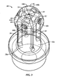
- Fig. 3 is a semi-transparent perspective view of a collect mechanism in accordance with the first preferred embodiment of the present invention
- Fig. 4 is a perspective view of a partial collect mechanism shown in Fig. 3 following injection molding with the mold removed;
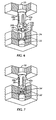
- Fig. 5A is an enlarged perspective view of cannula guides of the collet mechanism shown in Fig. 3 in an open position;
- Fig. 5B is an enlarged perspective view of the cannula guides shown in Fig. 5A in a closed position;
- Fig. 6 a perspective schematic view, partially in section, of the collect mechanism and a portion of the mold in an open position
- Fig. 7 is a perspective schematic view, partially in section of the collect mechanism and a portion of the mold shown in Fig. 6 in a closed position;
- Fig. 8 is a semi-transparent perspective view of a collect mechanism in accordance with a second preferred embodiment of the present invention.
- Fig. 9 is a top plan view of the collect mechanism shown in Fig. 8 ;
- Fig. 10 is a perspective view of cannula guides of the collect mechanism shown in Fig. 8 in a closed position;
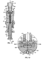
- Fig. 11 is a cross sectional view of the collect mechanism shown in Fig. 3 and mold components;
- Fig. 12 is a greatly enlarged cross sectional view of the collect mechanism and mold shown in Fig. 11 taken about area 12 in Fig. 11 ;
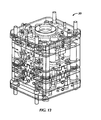
- Fig. 13 is a semi-transparent perspective view of the mold encasement for the collet and mold components shown in Fig. 11 .
- a collet mechanism 10 is used to position and hold a cannula 12 in place during insert or another type of molding of a staked needle, generally 14, without damaging the cannula 12.
- the staked needle 14 is comprised of a polymeric barrel 16 that is directly insert molded over the cannula 12.
- the barrel 16 is preferably comprised of a transparent cyclic olefin copolymer or polymer (COC or COP).
- the barrel 16 may also be a co-injected or multi-component polymer barrel comprising an alternative enhanced barrier polymer constituent
- the distal tip 16a of the barrel 16 extends over a proximal end 12b of the cannula 12 and includes a tapered distal end 17.
- the cannula 12 is to be securely attached to the distal tip 16a of the barrel 16 that is directly insert molded over the cannula 12.
- the distal end 17 is generally hollow, so as to form a sleeve around the cannula 12 ( Figs. 1E and 1F ). Hollowing out the interior of the distal end 17 around the cannula 12 prevents molten polymeric material from entering into the hollow cannula during the molding process, which would result in an occluded and unusable cannula. Further, hollowing out the interior of the distal end 17 around the cannula 12 reduces the amount of polymeric material in contact with the cannula 12 and therefore further reduces the cooling time required for the insert molding process, as described below.
- the distal end 17 is sufficiently sized and tapered to allow for cannula or needle shields (not shown), generally manufactured for use with staked glass needles, to be attached to the barrel 16 in a similar manner.
- the cannula 12 is preferably a fine gauge (i.e. 27 to 33 gauge) hollow metallic needle.
- a 27 gauge needle typically has a nominal outer diameter of 0.0160 to 0.0165 inch (0,041-0,042 cm) and a nominal inner diameter of 0.0075 to 0.0090 inch (0,019-0,023 cm) gauge needle typically has a nominal outer diameter of 0.0080 to 0.0085 inch (0,020-0,022 cm) and a nominal inner diameter of 0.0035 to 0.0050 inch (0,009 - 0,013 cm).
- the interior lumen 13 of the cannula 12 is preferably straight.
- the cannula 12 preferably has a tip 12a with a three-bevel grind, meaning that the tip 12a is tapered at three distinct angles to reduce the pain perceived by a patient during use of the staked needle 14.
- a plurality of notches 18 are preferably formed on the outer surface of at least a portion of the proximal end 12b of the cannula 12.
- the notches 18 preferably extend radially inwardly and are axially spaced apart from each other.
- the notches 18 are preferably machined into the proximal end 12b of the cannula 12.
- the notches 18 aid in affixing or securing the proximal end 12b of the cannula 12 to the tip 16a of the barrel 16 because the polymeric material forming the tip 16a flows into and fills in the notches 18 during the molding process, as described below, to provide enhanced friction and gripping force between the proximal end 12b and the barrel tip 16a.
- the cannula 12 may not be crimped without potentially damaging the cannula 12 due to its size, the notches 18 which are formed in the cannula 12 replace the function of crimping the cannula 12, as used in the prior art described above.
- a portion 12c of the proximal end 12b of the cannula 12 extends through the tip 16a and into the barrel 16 due to the molding process, as described further bellow.
- At least a portion of the proximal end 12b of the cannula 12 may also be textured or toughened (shown in Fig.
- the collet mechanism 10 has first and second axially extending flexible arms 38, 40 that form an expandable internal cavity 46 (see Figs. 6 and 12 ), but may include any number of flexible arms. While flexible arms are used in the present embodiment, it would be apparent to one of ordinary skill in the art that any other suitable type of arms may be employed.
- the collect mechanism 10 further includes third and fourth flexible arms 42, 44.
- Each flexible arm 38, 40, 42, 44 has an attached proximal end 38a, 40a, 42a (the proximal end of the fourth flexible arm 44 obstructed from view) and a free or unattached distal end 38b, 40b, 42b, 44b.
- the flexible arms 38, 40, 42, 44 may be moved or flexed inwardly and outwardly with the greatest deflection occurring toward the distal ends 38b, 40b, 42b, 44b.
- the flexible arms 38, 40, 42, 44 are in a closed position ( Figs. 3 and 7 ) when the distal ends 38b, 40b, 42b, 44b are moved or flexed inwardly, toward the internal cavity 46.
- the flexible arms 38, 40, 42, 44 are in an open position ( Fig. 6 ) when the distal ends 38b, 40b, 42b, 44b of the flexible arms 38, 40, 42, 44 are moved or positioned away from the internal cavity 46 (e.g., flexed outwardly).
- the open position of the collet mechanism 10 is preferably the unrestrained state, meaning that the distal ends 38b, 40b, 42b, 44b are untouched, and the closed position of the collet mechanism 10 is preferably the restrained position, meaning that the distal ends 38b, 40b, 42b, 44b are forced together by an outside force, though the opposite configuration may be used if desired.
- the first and second flexible arms 38, 40 include first and second cannula guides 48, 50, respectively.
- the first cannula guide 48 is preferably directly opposed from the second cannula guide 50.
- the third and fourth flexible arms 42, 44 include third and fourth cannula guides 52, 54, respectively, the third cannula guide 52 preferably being directly opposed from the fourth cannula guide 54.
- the cannula guides 48, 50, 52, 54 are preferably comprised of a polytetrafluoroethylene material, a plastic with nonstick properties such as TEFLON ®, that is gentle on the cannula 12 so as not to indent or alter the outer surface of the cannula 12 when the cannula guides 48, 50, 52, 54 are in contact with the cannula 12, but that resists the elevated temperature of the mold 20.
- the cannula guides 48, 50, 52, 54 may be comprised of any heat resistant polymeric material or some other material, such as stainless steel.
- the cannula guides 48, 50, 52, 54 are mounted proximate to and positioned through the distal ends 38b, 40b, 42b, 44b of the respective flexible arms 38, 40, 42, 44 and extend radially at least partially into the expandable internal cavity 46.
- the cannula guides 48, 50, 52, 54 are preferably generally orthogonal to the flexible arms 38, 40, 42, 44.
- the cannula guides 48, 50, 52, 54 clamp a portion of the cannula 12 to hold the cannula 12 in place when the flexible arms 38, 40, 42, 44 are in the closed position ( Fig. 5B ).
- the cannula guides 48, 50, 52, 54 are spaced away from the cannula 12 when the flexible arms 38, 40, 42, 44 are in the open position ( Fig. 5A ).
- a position of the cannula guides 48, 50, 52, 54 is preferably adjustable with respect to the flexible arms 38, 40, 42, 44 and the internal cavity 46 with a tool, such as an Allen wrench, by inserting the tool into adjustment openings 60 of the cannula guides 48, 50, 52, 54 to position the cannula guides 48, 50, 52, 54 at a predetermined depth into the internal cavity 46. Because the size of the cannula 12 may change and the size of the collect mechanism 10 may vary slightly, the adjustability of the position of the cannula guides 48, 50, 52, 54 allows a user to adjust and set the pressure exerted on the cannula 12 and the resulting force with which the cannula guides 48, 50, 52, 54 contact the cannula 12.
- a tool such as an Allen wrench
- the position of the cannula guides 48, 50, 52, 54 may be adjusted in accordance with a predetermined force.
- the cannula guides 48, 50, 52, 54 can sufficiently position and hold the cannula 12 in the desired position without damaging (i.e. bending, crimping or scratching) the cannula 12, but with sufficient force to retain the cannula 12 without allowing movement during the injection, insert or other molding process.
- the cannula guides 48, 50, 52, 54 exert a predetermined amount of force upon the cannula 12 when in the closed position and in contact with the cannula 12, such that the cannula 12 is not damaged and the sharpness of the tip 12a of the cannula 12 is not altered during the molding process.
- the cannula guides 48, 50, 52, 54 be immovably mounted to the respective flexible arm 38, 40, 42, 44.
- each cannula guide 48, 50, 52, 54 preferably has a sloped mating surface 56 with an indentation or step 58 formed in the center, but may have any mating configuration, such as mating V-shaped members. As shown in Fig.
- the first and second cannula guides 48, 50 come into mating contact with each other and the third and fourth cannula guides 52, 54 come into mating contact with each other, and all of the cannula guides 48, 50, 52, 54 come into contact with the cannula 12, such that the cannula 12 slides along the sloped mating surface 56 into the indentation 58 of each of the cannula guides 48, 50, 52, 54.
- each indentation 58 abuts the cannula 12, such that the cannula 12 is positioned and held firmly along the center of the collet mechanism 10, generally in alignment with a central longitudinal axis 10a of the collet mechanism 10 (see Fig. 4 ), and inline with the centerline 14a of the staked needle 14.
- the cannula guides 48, 50, 52, 54 may mate together in any manner, such as all four guides mating together, as long as the cannula 12 is sufficiently held in place without damage during the injection, insert or other molding process.
- each cannula guide 148, 150, 152, 154 includes a coil spring 162 or other suitable biasing member to bias the cannula guides 148, 150, 152, 154. While springs 162 are used to bias the cannula guides 148, 150, 152, 154 in the present embodiment, it would be apparent to one of ordinary skill in the art that any other suitable type of mechanism may be employed.
- the collect mechanism 110 includes similar elements to the collect mechanism 10 and such elements have been similarly numbered with the addition of a leading one.
- a mounting member 164 is secured to the distal ends 138b, 140b, 142b, 144b of each of the flexible arms 138, 140, 142, 144.
- the coil springs 162 are positioned between the mounting members 164 and the cannula guides 148, 150, 152, 154 such that the cannula guides 148, 150, 152, 154 may accommodate differently sized cannulas 12 or may be used in order to ensure that the cannula guides 148, 150, 152, 154 contact and firmly hold the cannula 12 without the need for adjustment.
- the springs 162 are preferably replaceable such that springs 162 having the desired bias or pressure for the particular cannula size are used. It is within the spirit and scope of the present invention that the first and second embodiments of the collet mechanism 10, 110 be combined such that the cannula guides 48, 50, 52, 54 and 148, 150, 152, 154 may be both adjustable and spring biased.
- the insert mold 20 includes an A-side mold 22 and a B-side mold 24, separable along a parting line 26, shown in Fig. 11 .
- the mold cavity 30 is in the shape of the to-be-formed barrel 16.
- a cooling cavity 32 preferably extends through the center of the core member 28 to cool the core member 28 during molding.
- the A-side mold 22 includes a conically tapered receiving port 34 positioned above the core member 28 where the tip 16a of the barrel 16 is to be formed. The tapered receiving port 34 at least partially surrounds a portion of the cannula 12.
- a robotic arm transports the cannula 12 and places the proximal end 12b of the cannula 12 onto a recessed tip 28a of the core member 28.
- the tip 28a of the core member 28 receives the portion 12c of the cannula 12 and positions the cannula 12 generally inline with a center line 14a (see Fig. 1F ) of the staked needle 14.
- the A-side mold 22 is inserted over the steel core member 28 such that the A-side mold 22 contacts the B-side mold 24 along the parting line 26.
- the tip 12a of the cannula 12 extends at least partially through the receiving port 34.
- the collet mechanism 10 preferably having flexible arms 38,40,42,44 with distal ends 33b, 40b, 42b, 44b, is inserted through the A-side mold 22 over the beveled tip 12a of the cannula 12, such that the distal end 10b of the collet mechanism 10 is guided by the tapered receiving port 34 to move the collet mechanism 10 into the closed position.
- the distal ends 38b, 40b, 42b, 44b of the flexible arms 3% 40, 42, 44 are inserted into the tapered receiving port 34 which moves or flexes the flexible arms 38, 40, 42, 44 toward the internal cavity 46 as the distal ends 38b, 40b, 42b, 44b slide along the taper of the tapered receiving port 34, until the collet mechanism 10 abuts the A-side mold 22. Once the collet mechanism 10 abuts the A-side mold 22, or is otherwise stopped, and the distal ends 38b, 40b, 42b, 44b are fully received in the receiving port 34 as shown in Figs. 11 and 12 , the collet mechanism 10 is in the closed position.
- the cannula guides 48, 50, 52, 54 clamp a portion of the cannula 12 spaced away from the tip 12a of the cannula 12 to hold the cannula 12 generally in alignment with the central longitudinal axis 10a of the collet mechanism 10 and with a central longitudinal axis 28b of the core member 28.
- the cannula 12 extends beyond the distal ends 38b, 40b, 42b, 44b of the flexible arms 38, 40, 42, 44 and, thus, the collet mechanism 10 does not damage the beveled tip 12a of the cannula 12.
- the cannula 12 is positioned and firmly held in the center of the internal cavity 46 and is generally inline with the centerline 14a of the staked needle 14 (see Fig. ID).
- molten polymeric material (not shown) is injected into the mold cavity 30 proximate the parting line 26 (dispensing line not shown) until the mold cavity 30 is completely filled with the molten polymeric material.
- the mold 20 operates at a temperature of approximately 230°F (110°C).
- the mold 20 remains closed and the molten polymeric material is then allowed to cool to a substantially solidified state over at least the proximal end 12b of the cannula 12. It may take approximately 30 seconds for the polymeric material to substantially solidify.
- the collet mechanism 10 and the A-side mold 22 is removed, such that the cannula guides 48, 50, 52, 54 release the cannula 12.
- the staked needle 14 and attached cannula 12 are then removed from the steel core member 28 by a robotic arm (not shown), and the polymeric material is allowed to further cool and solidify, if necessary, to a fully hardened object.
Landscapes
- Engineering & Computer Science (AREA)
- Health & Medical Sciences (AREA)
- Manufacturing & Machinery (AREA)
- Mechanical Engineering (AREA)
- Hematology (AREA)
- Anesthesiology (AREA)
- Biomedical Technology (AREA)
- Heart & Thoracic Surgery (AREA)
- Vascular Medicine (AREA)
- Life Sciences & Earth Sciences (AREA)
- Animal Behavior & Ethology (AREA)
- General Health & Medical Sciences (AREA)
- Public Health (AREA)
- Veterinary Medicine (AREA)
- Moulds For Moulding Plastics Or The Like (AREA)
- Infusion, Injection, And Reservoir Apparatuses (AREA)
- Injection Moulding Of Plastics Or The Like (AREA)
Description
- The present invention relates to a collet mechanism and a method of molding a cannula to a syringe barrel, specifically the collet mechanism and method of molding a fine gauge cannula to a polymeric syringe barrel to form a staked needle device.
- The process of bonding a cannula to a syringe barrel is a critical step in the manufacture of syringes. The cannula must be precisely positioned and then bonded to the syringe without being damaged. The slightest bend or burr in the end of the cannula increases the perceived pain by a patient. The cannula is preferably directly inline with the center axis of the syringe. The cannula must also be sufficiently bonded to the syringe to withstand a minimum 22N pull test rating in accordance with the International Standards Organization's (ISO's) standards. For polymeric syringes, the cannula is typically interference fit into a preformed syringe barrel in a similar manner to what is done with a glass syringe. The cannula is often affixed to the syringe by an adhesive. However, it is undesirable to use an adhesive to affix a cannula to a syringe because the adhesive may contain toxic chemicals that could leach into the syringe contents, comprised of one or more drug(s)/biological compound(s), and could alter the efficacy and/or stability of the syringe contents that eventually enter the patient.
- In order to avoid the use of an adhesive, the cannula (typically a 25 gauge needle or larger) is typically crimped toward its proximal end and then the syringe barrel is insert molded over the proximal end of the cannula, so that the syringe molds over the crimped proximal end to securely grip and retain the cannula to the syringe. Though crimping the proximal end may avoid the use of an adhesive, finer gauge cannulas (i.e. 27 to 33 gauge) cannot usually be crimped without potentially damaging the cannula due to their small physical dimensions. Specifically, due to the very thin wall of the tubing of such finer gauge cannulas, it is physically impossible to crimp the outside diameter of such cannulas without completely closing down the inner diameter of the cannulas. Regardless of the attachment method, it is difficult to position, hold, and/or mount a fragile, fine gauge cannula without damaging the cannula.
-
GB 1207229 A CH 657990 A5 - What is therefore needed, but not provided in the prior art, is a mechanism that holds the cannula, particularly a small diameter cannula, in place during the molding process to securely attach the cannula directly to a polymeric syringe barrel without the use of an adhesive or the need to crimp the cannula, and without damaging the cannula, specifically the sharp beveled tip of the cannula.
- Briefly stated, the present application is directed to a collet mechanism for holding a cannula during molding of a syringe. The collet mechanism includes first and second arms which form an internal cavity. Each arm has a proximal end and a distal end. The first and second arms are in a closed position when the distal ends are moved toward the internal cavity and are in an open position when the distal ends are positioned away from the internal cavity. First and second cannula guides respectively are mounted proximate the distal ends of the first and second arms and extend into the internal cavity. The first and second cannula guides clamp a portion of the cannula to hold the cannula when the first and second arms are in the closed position.
- In another aspect, the present application is directed to a method of manufacturing a syringe. The method includes the steps of: placing a cannula having a beveled tip onto a recessed tip of a core member; placing a mold over the core member, the mold having a tapered receiving port at least partially surrounding at least a portion the cannula; inserting a collet mechanism having at least two cannula guides through the mold and over the beveled tip of the cannula, a distal end of the collet mechanism being guided by the tapered receiving port to move the collet mechanism into a closed position wherein the cannula guides clamp a portion of the cannula to hold the cannula generally in alignment with a longitudinal axis of the collet mechanism and with a longitudinal axis of the core member; injecting polymeric material into the mold; allowing the polymeric material to cool until substantially solidified over at least a proximal end of the cannula; removing the collet mechanism from the mold such that the cannula guides release the cannula; removing the mold; and removing the syringe and attached cannula from the core member.
- In a further aspect, the present application is directed a cannula having an outside diameter in the range of 0.0080 to 0.0165 inches (0,020-0,042 cm) for attachment to a tip of a polymeric syringe barrel that is molded over the cannula. At least a portion of a proximal end of the cannula has a plurality of notches formed on an outer surface.
- The following detailed description of the preferred embodiments of the invention, will be better understood when read in conjunction with the appended drawings. For the purpose of illustrating the invention, there are shown in the drawings embodiments which are presently preferred. It should be understood, however, that the invention is not limited to the precise arrangements and instrumentalities shown.
- In the drawings:
-
Fig. 1A is a perspective view of a staked needle formed through the use of a collet mechanism in accordance with a first preferred embodiment of the present invention; -
Fig. 1B is an enlarged rear elevational view of the staked needle shown inFig. 1A ; -
Fig. 1C is an enlarged front elevational view of the staked needle shown inFig. 1A ; -
Fig. 1D is an enlarged side elevational view of the staked needle shown inFig. 1A ; -
Fig. 1E is an enlarged cross-sectional view of the staked needle shown inFig. 1A taken along line E-E inFig. 1B ; - Fig. IF is a greatly enlarged cross-sectional view of the needle end of the staked needle shown in
Fig. 1A taken about area F-F inFig. 1E ; -
Fig. 2A is a greatly enlarged perspective view of a needle tip of the staked needle shown inFig. 1A ; -
Fig. 2B is a greatly enlarged side elevational view of the needle tip shown inFig. 2A ; -
Fig. 2C is a greatly enlarged side elevational view of the proximal end of the needle shown inFig. 2A ; -
Fig. 3 is a semi-transparent perspective view of a collect mechanism in accordance with the first preferred embodiment of the present invention; -
Fig. 4 is a perspective view of a partial collect mechanism shown inFig. 3 following injection molding with the mold removed; -
Fig. 5A is an enlarged perspective view of cannula guides of the collet mechanism shown inFig. 3 in an open position; -
Fig. 5B is an enlarged perspective view of the cannula guides shown inFig. 5A in a closed position; -
Fig. 6 a perspective schematic view, partially in section, of the collect mechanism and a portion of the mold in an open position; -
Fig. 7 is a perspective schematic view, partially in section of the collect mechanism and a portion of the mold shown inFig. 6 in a closed position; -
Fig. 8 is a semi-transparent perspective view of a collect mechanism in accordance with a second preferred embodiment of the present invention; -
Fig. 9 is a top plan view of the collect mechanism shown inFig. 8 ; -
Fig. 10 is a perspective view of cannula guides of the collect mechanism shown inFig. 8 in a closed position; -
Fig. 11 is a cross sectional view of the collect mechanism shown inFig. 3 and mold components; -
Fig. 12 is a greatly enlarged cross sectional view of the collect mechanism and mold shown inFig. 11 taken aboutarea 12 inFig. 11 ; and -
Fig. 13 is a semi-transparent perspective view of the mold encasement for the collet and mold components shown inFig. 11 . - Certain terminology is used in the following description for convenience only and is not limiting. The words "right", "left", "lower" and "upper" designate directions in the drawings to which reference is made. The words "inwardly" and "outwardly" refer to directions toward and away from, respectively, the geometric center of the collet mechanism and designated parts thereof. Unless specifically set forth herein, the terms "a", "an" and "the" are not limited to one element but instead should be read as meaning "at least one". The terminology includes the words noted above, derivatives thereof and words of similar import.
- Referring to the drawings, wherein like numerals indicate like elements throughout, there is shown in
Figs. 3-7 and11-13 a first preferred embodiment of acollet mechanism 10. Thecollet mechanism 10 is used to position and hold acannula 12 in place during insert or another type of molding of a staked needle, generally 14, without damaging thecannula 12. - Referring to
Figs. 1A-2C , the stakedneedle 14 is comprised of apolymeric barrel 16 that is directly insert molded over thecannula 12. Thebarrel 16 is preferably comprised of a transparent cyclic olefin copolymer or polymer (COC or COP). Thebarrel 16 may also be a co-injected or multi-component polymer barrel comprising an alternative enhanced barrier polymer constituent Thedistal tip 16a of thebarrel 16 extends over aproximal end 12b of thecannula 12 and includes a tapereddistal end 17. Thecannula 12 is to be securely attached to thedistal tip 16a of thebarrel 16 that is directly insert molded over thecannula 12. Thedistal end 17 is generally hollow, so as to form a sleeve around the cannula 12 (Figs. 1E and 1F ). Hollowing out the interior of thedistal end 17 around thecannula 12 prevents molten polymeric material from entering into the hollow cannula during the molding process, which would result in an occluded and unusable cannula. Further, hollowing out the interior of thedistal end 17 around thecannula 12 reduces the amount of polymeric material in contact with thecannula 12 and therefore further reduces the cooling time required for the insert molding process, as described below. Thedistal end 17 is sufficiently sized and tapered to allow for cannula or needle shields (not shown), generally manufactured for use with staked glass needles, to be attached to thebarrel 16 in a similar manner. - Referring specifically to
Figs. 2A-2C , thecannula 12 is preferably a fine gauge (i.e. 27 to 33 gauge) hollow metallic needle. A 27 gauge needle typically has a nominal outer diameter of 0.0160 to 0.0165 inch (0,041-0,042 cm) and a nominal inner diameter of 0.0075 to 0.0090 inch (0,019-0,023 cm) gauge needle typically has a nominal outer diameter of 0.0080 to 0.0085 inch (0,020-0,022 cm) and a nominal inner diameter of 0.0035 to 0.0050 inch (0,009 - 0,013 cm). Theinterior lumen 13 of thecannula 12 is preferably straight. Thecannula 12 preferably has atip 12a with a three-bevel grind, meaning that thetip 12a is tapered at three distinct angles to reduce the pain perceived by a patient during use of the stakedneedle 14. - A plurality of
notches 18 are preferably formed on the outer surface of at least a portion of theproximal end 12b of thecannula 12. Thenotches 18 preferably extend radially inwardly and are axially spaced apart from each other. Thenotches 18 are preferably machined into theproximal end 12b of thecannula 12. Thenotches 18 aid in affixing or securing theproximal end 12b of thecannula 12 to thetip 16a of thebarrel 16 because the polymeric material forming thetip 16a flows into and fills in thenotches 18 during the molding process, as described below, to provide enhanced friction and gripping force between theproximal end 12b and thebarrel tip 16a. Because thecannula 12 may not be crimped without potentially damaging thecannula 12 due to its size, thenotches 18 which are formed in thecannula 12 replace the function of crimping thecannula 12, as used in the prior art described above. As shown in Fig. IF, aportion 12c of theproximal end 12b of thecannula 12 extends through thetip 16a and into thebarrel 16 due to the molding process, as described further bellow. At least a portion of theproximal end 12b of thecannula 12 may also be textured or toughened (shown inFig. 2C with cross hatching) by a mechanical or chemical surface treatment, including ablation, to further enhance the gripping force of theproximal end 12b of thecannula 12 and to better secure theproximal end 12b to thetip 16a of thebarrel 16. Though the above describedcannula 12 is preferred, it is within the spirit and scope of the present invention that any size and shaped cannula may be used. - Referring to specifically to
Figs. 3-5B , thecollet mechanism 10 has first and second axially extendingflexible arms Figs. 6 and12 ), but may include any number of flexible arms. While flexible arms are used in the present embodiment, it would be apparent to one of ordinary skill in the art that any other suitable type of arms may be employed. Preferably, thecollect mechanism 10 further includes third and fourthflexible arms flexible arm proximal end flexible arm 44 obstructed from view) and a free or unattacheddistal end flexible arms flexible arms Figs. 3 and7 ) when the distal ends 38b, 40b, 42b, 44b are moved or flexed inwardly, toward theinternal cavity 46. Theflexible arms Fig. 6 ) when the distal ends 38b, 40b, 42b, 44b of theflexible arms collet mechanism 10 is preferably the unrestrained state, meaning that the distal ends 38b, 40b, 42b, 44b are untouched, and the closed position of thecollet mechanism 10 is preferably the restrained position, meaning that the distal ends 38b, 40b, 42b, 44b are forced together by an outside force, though the opposite configuration may be used if desired. - Referring specifically to
Figs. 5A and 5B , the first and secondflexible arms first cannula guide 48 is preferably directly opposed from thesecond cannula guide 50. Preferably, the third and fourthflexible arms third cannula guide 52 preferably being directly opposed from thefourth cannula guide 54. The cannula guides 48, 50, 52, 54 are preferably comprised of a polytetrafluoroethylene material, a plastic with nonstick properties such as TEFLON ®, that is gentle on thecannula 12 so as not to indent or alter the outer surface of thecannula 12 when the cannula guides 48, 50, 52, 54 are in contact with thecannula 12, but that resists the elevated temperature of themold 20. However, the cannula guides 48, 50, 52, 54 may be comprised of any heat resistant polymeric material or some other material, such as stainless steel. - The cannula guides 48, 50, 52, 54 are mounted proximate to and positioned through the distal ends 38b, 40b, 42b, 44b of the respective
flexible arms internal cavity 46. The cannula guides 48, 50, 52, 54 are preferably generally orthogonal to theflexible arms cannula 12 to hold thecannula 12 in place when theflexible arms Fig. 5B ). The cannula guides 48, 50, 52, 54 are spaced away from thecannula 12 when theflexible arms Fig. 5A ). - A position of the cannula guides 48, 50, 52, 54 is preferably adjustable with respect to the
flexible arms internal cavity 46 with a tool, such as an Allen wrench, by inserting the tool intoadjustment openings 60 of the cannula guides 48, 50, 52, 54 to position the cannula guides 48, 50, 52, 54 at a predetermined depth into theinternal cavity 46. Because the size of thecannula 12 may change and the size of thecollect mechanism 10 may vary slightly, the adjustability of the position of the cannula guides 48, 50, 52, 54 allows a user to adjust and set the pressure exerted on thecannula 12 and the resulting force with which the cannula guides 48, 50, 52, 54 contact thecannula 12. Preferably, the position of the cannula guides 48, 50, 52, 54 may be adjusted in accordance with a predetermined force. Thus, the cannula guides 48, 50, 52, 54 can sufficiently position and hold thecannula 12 in the desired position without damaging (i.e. bending, crimping or scratching) thecannula 12, but with sufficient force to retain thecannula 12 without allowing movement during the injection, insert or other molding process. Preferably, the cannula guides 48, 50, 52, 54 exert a predetermined amount of force upon thecannula 12 when in the closed position and in contact with thecannula 12, such that thecannula 12 is not damaged and the sharpness of thetip 12a of thecannula 12 is not altered during the molding process. However, it is within the spirit and scope of the present invention that the cannula guides 48, 50, 52, 54 be immovably mounted to the respectiveflexible arm - Referring again to
Figs. 5A and 5B , eachcannula guide mating surface 56 with an indentation or step 58 formed in the center, but may have any mating configuration, such as mating V-shaped members. As shown inFig. 5B , as theflexible arms cannula 12, such that thecannula 12 slides along the slopedmating surface 56 into theindentation 58 of each of the cannula guides 48, 50, 52, 54. When theflexible arms indentation 58 abuts thecannula 12, such that thecannula 12 is positioned and held firmly along the center of thecollet mechanism 10, generally in alignment with a centrallongitudinal axis 10a of the collet mechanism 10 (seeFig. 4 ), and inline with the centerline 14a of the stakedneedle 14. The cannula guides 48, 50, 52, 54 may mate together in any manner, such as all four guides mating together, as long as thecannula 12 is sufficiently held in place without damage during the injection, insert or other molding process. - Referring to
Figs. 8-10 , a second preferred embodiment of thecollet mechanism 110 is shown. Thecollet mechanism 110 is similar to the first preferred embodiment of thecollet mechanism 10, except that the cannula guides 148, 150, 152, 154 are each biased toward the closed position. Preferably, eachcannula guide coil spring 162 or other suitable biasing member to bias the cannula guides 148, 150, 152, 154. Whilesprings 162 are used to bias the cannula guides 148, 150, 152, 154 in the present embodiment, it would be apparent to one of ordinary skill in the art that any other suitable type of mechanism may be employed. Thecollect mechanism 110 includes similar elements to thecollect mechanism 10 and such elements have been similarly numbered with the addition of a leading one. A mountingmember 164 is secured to the distal ends 138b, 140b, 142b, 144b of each of theflexible arms members 164 and the cannula guides 148, 150, 152, 154 such that the cannula guides 148, 150, 152, 154 may accommodate differentlysized cannulas 12 or may be used in order to ensure that the cannula guides 148, 150, 152, 154 contact and firmly hold thecannula 12 without the need for adjustment. Thesprings 162 are preferably replaceable such that springs 162 having the desired bias or pressure for the particular cannula size are used. It is within the spirit and scope of the present invention that the first and second embodiments of thecollet mechanism - Referring to
Figs. 11-13 , the stakedneedle 14 is manufactured in an insert mold 20 (Fig. 11 ). Theinsert mold 20 includes anA-side mold 22 and a B-side mold 24, separable along aparting line 26, shown inFig. 11 . Acore member 28, preferably comprised of steel, extends from the B-side mold 24 upwardly and into amold cavity 30 in theA-side mold 22. Themold cavity 30 is in the shape of the to-be-formed barrel 16. A coolingcavity 32 preferably extends through the center of thecore member 28 to cool thecore member 28 during molding. TheA-side mold 22 includes a conically tapered receivingport 34 positioned above thecore member 28 where thetip 16a of thebarrel 16 is to be formed. The tapered receivingport 34 at least partially surrounds a portion of thecannula 12. - Referring to
Figs. 6-7 and11-12 , during molding of the stakedneedle 14, a robotic arm (not shown) transports thecannula 12 and places theproximal end 12b of thecannula 12 onto a recessedtip 28a of thecore member 28. Thetip 28a of thecore member 28 receives theportion 12c of thecannula 12 and positions thecannula 12 generally inline with a center line 14a (seeFig. 1F ) of the stakedneedle 14. TheA-side mold 22 is inserted over thesteel core member 28 such that theA-side mold 22 contacts the B-side mold 24 along theparting line 26. Thetip 12a of thecannula 12 extends at least partially through the receivingport 34. - Once the
cannula 12 andA-side mold 22 have been positioned on thecore member 28, thecollet mechanism 10, preferably havingflexible arms distal ends A-side mold 22 over thebeveled tip 12a of thecannula 12, such that thedistal end 10b of thecollet mechanism 10 is guided by the tapered receivingport 34 to move thecollet mechanism 10 into the closed position. More specifically, the distal ends 38b, 40b, 42b, 44b of the flexible arms 3% 40, 42, 44 are inserted into the tapered receivingport 34 which moves or flexes theflexible arms internal cavity 46 as the distal ends 38b, 40b, 42b, 44b slide along the taper of the tapered receivingport 34, until thecollet mechanism 10 abuts theA-side mold 22. Once thecollet mechanism 10 abuts theA-side mold 22, or is otherwise stopped, and the distal ends 38b, 40b, 42b, 44b are fully received in the receivingport 34 as shown inFigs. 11 and 12 , thecollet mechanism 10 is in the closed position. In the closed position, the cannula guides 48, 50, 52, 54 clamp a portion of thecannula 12 spaced away from thetip 12a of thecannula 12 to hold thecannula 12 generally in alignment with the centrallongitudinal axis 10a of thecollet mechanism 10 and with a centrallongitudinal axis 28b of thecore member 28. Thecannula 12 extends beyond the distal ends 38b, 40b, 42b, 44b of theflexible arms collet mechanism 10 does not damage thebeveled tip 12a of thecannula 12. Further, in the closed position, thecannula 12 is positioned and firmly held in the center of theinternal cavity 46 and is generally inline with the centerline 14a of the staked needle 14 (see Fig. ID). - Referring specifically to
Fig. 11 , once thecollet mechanism 10 is in place within theA-side mold 22 of themold 20, molten polymeric material (not shown) is injected into themold cavity 30 proximate the parting line 26 (dispensing line not shown) until themold cavity 30 is completely filled with the molten polymeric material. Themold 20 operates at a temperature of approximately 230°F (110°C). Themold 20 remains closed and the molten polymeric material is then allowed to cool to a substantially solidified state over at least theproximal end 12b of thecannula 12. It may take approximately 30 seconds for the polymeric material to substantially solidify. Once the polymeric material is cooled to a semi-hardened object, and preferably, a fully hardened object, thecollet mechanism 10 and theA-side mold 22 is removed, such that the cannula guides 48, 50, 52, 54 release thecannula 12. The stakedneedle 14 and attachedcannula 12 are then removed from thesteel core member 28 by a robotic arm (not shown), and the polymeric material is allowed to further cool and solidify, if necessary, to a fully hardened object.
Claims (10)
- A collet mechanism (10) for holding a cannula (12) during molding of a .syringe, the collet mechanism (10) being characterized by:first and second arms (38, 40) forming an internal cavity (46), each arm having a proximal end (38a, 40a) and a distal end (38b, 40b(), the first and second arms (38, 40) being in a closed position when the distal ends (38b, 40b) are moved toward the internal cavity (46) and being in an open position when the distal ends (38b, 40b) are positioned away from the internal cavity (46);first and second cannula guides (48, 50) respectively mounted proximate the distal ends (38b, 40b) of the first and second arms (38, 40) and extending into the internal cavity (46), which first and second cannula guides (48, 50) may clamp a portion of the cannula (12) to hold the cannula (12) when the first and second arms (38, 40) are in the closed position.
- The collet mechanism of claim 1, wherein the first and second cannula guides (48, 50) are positioned opposite each other.
- The collet mechanism of claim 1, wherein the first and second cannula guides (48, 50) are spaced away from the cannula (12) when the first and second arms (3 8, 40) are in the open position.
- The collet mechanism of claim 1 further comprising third and fourth arms (42, 44), each arm having a distal end (42b, 44b) and a cannula guide (52, 54) mounted proximate the distal end (42b, 44b).
- The collet mechanism of claim 1, wherein a position of the first and second cannula guides (48, 50) is adjustable with respect to the first and second arms (38, 40) and the internal cavity (46) such that the force with which the first and second cannula guides (48, 50) contact the cannula (12) is adjustable.
- The collet mechanism of claim 1, wherein the first and second cannula guides (48, 50) contact the cannula (12) at a position spaced away from a tip (12a) of the cannula (12) with a predetermined force such that the cannula (12) is not damaged and the sharpness of the tip (12a) of the cannula (12) is not altered when the first and second arms (38, 40) are in the closed position.
- The collet mechanism of claim 1, wherein a surface (56) of each of the first and second cannula guides (48, 50) is sloped, the sloped surfaces (56) each having an indentation (58) formed therein.
- The collet mechanism of claim 7, wherein the indentations (58) abut the cannula (12) when the first and second arms (38, 40) are in the closed position.
- The collet mechanism of claim 1, wherein the cannula guides (48, 50) are biased toward the closed position.
- A method of manufacturing a syringe comprising the steps of:placing a cannula (12) having a beveled tip (12a) onto a recessed tip (28a) of a core member (28);placing a mold (20) over the core member (28), the mold (20) having a tapered receiving port (34) at least partially surrounding at least a portion of the cannula (12);inserting a collet mechanism (10) having at least two cannula guides (48, 50) through the mold (20) and over the beveled tip (12a) of the cannula (12), a distal end (38b, 40b) of the collet mechanism (10) being guided by the tapered receiving port (34) to move the collet mechanism (10) into a closed position wherein the cannula guides (48, 50) clamp a portion of the cannula (12) to hold the cannula (12) generally in alignment with a longitudinal axis of the collet mechanism (10) and with a longitudinal axis of the core member (28);injecting polymeric material into the mold;allowing the polymeric material to cool until substantially solidified over at least a proximal end of the cannula (12);removing the collet mechanism (10) from the mold (20) such that the cannula guides (48, 50) release the cannula (12);removing the mold (20); andremoving the syringe and attached cannula (12) from the core member (20).
Priority Applications (1)
| Application Number | Priority Date | Filing Date | Title |
|---|---|---|---|
| EP12166374A EP2484401A1 (en) | 2008-01-15 | 2009-01-15 | A cannula with a syringe barrel |
Applications Claiming Priority (2)
| Application Number | Priority Date | Filing Date | Title |
|---|---|---|---|
| US2118608P | 2008-01-15 | 2008-01-15 | |
| PCT/US2009/031112 WO2009091895A2 (en) | 2008-01-15 | 2009-01-15 | Collet mechanism and method of molding cannula to a syringe barrel |
Related Child Applications (1)
| Application Number | Title | Priority Date | Filing Date |
|---|---|---|---|
| EP12166374.4 Division-Into | 2012-05-02 |
Publications (3)
| Publication Number | Publication Date |
|---|---|
| EP2229197A2 EP2229197A2 (en) | 2010-09-22 |
| EP2229197A4 EP2229197A4 (en) | 2011-10-05 |
| EP2229197B1 true EP2229197B1 (en) | 2012-11-07 |
Family
ID=40885882
Family Applications (2)
| Application Number | Title | Priority Date | Filing Date |
|---|---|---|---|
| EP12166374A Withdrawn EP2484401A1 (en) | 2008-01-15 | 2009-01-15 | A cannula with a syringe barrel |
| EP09702776A Active EP2229197B1 (en) | 2008-01-15 | 2009-01-15 | Collet mechanism and method of molding cannula to a syringe barrel |
Family Applications Before (1)
| Application Number | Title | Priority Date | Filing Date |
|---|---|---|---|
| EP12166374A Withdrawn EP2484401A1 (en) | 2008-01-15 | 2009-01-15 | A cannula with a syringe barrel |
Country Status (5)
| Country | Link |
|---|---|
| US (1) | US8496862B2 (en) |
| EP (2) | EP2484401A1 (en) |
| JP (1) | JP5232248B2 (en) |
| CN (2) | CN101896214B (en) |
| WO (1) | WO2009091895A2 (en) |
Cited By (1)
| Publication number | Priority date | Publication date | Assignee | Title |
|---|---|---|---|---|
| US10800077B2 (en) * | 2015-02-06 | 2020-10-13 | Aptar France Sas | Moulding assembly and method for producing a syringe body |
Families Citing this family (60)
| Publication number | Priority date | Publication date | Assignee | Title |
|---|---|---|---|---|
| AU2004271893B2 (en) * | 2003-08-28 | 2010-07-29 | Becton, Dickinson And Company | Intradermal injection device |
| US10420880B2 (en) | 2007-10-02 | 2019-09-24 | West Pharma. Services IL, Ltd. | Key for securing components of a drug delivery system during assembly and/or transport and methods of using same |
| US9656019B2 (en) | 2007-10-02 | 2017-05-23 | Medimop Medical Projects Ltd. | Apparatuses for securing components of a drug delivery system during transport and methods of using same |
| US9345836B2 (en) | 2007-10-02 | 2016-05-24 | Medimop Medical Projects Ltd. | Disengagement resistant telescoping assembly and unidirectional method of assembly for such |
| US9173997B2 (en) | 2007-10-02 | 2015-11-03 | Medimop Medical Projects Ltd. | External drug pump |
| US7967795B1 (en) | 2010-01-19 | 2011-06-28 | Lamodel Ltd. | Cartridge interface assembly with driving plunger |
| US9402643B2 (en) | 2008-01-15 | 2016-08-02 | Novartis Ag | Targeted illumination for surgical instrument |
| US8721603B2 (en) | 2008-01-15 | 2014-05-13 | West Pharmaceutical Services, Inc. | Syringe with co-molded hub and cannula |
| US9393369B2 (en) | 2008-09-15 | 2016-07-19 | Medimop Medical Projects Ltd. | Stabilized pen injector |
| US12097357B2 (en) | 2008-09-15 | 2024-09-24 | West Pharma. Services IL, Ltd. | Stabilized pen injector |
| US8157769B2 (en) | 2009-09-15 | 2012-04-17 | Medimop Medical Projects Ltd. | Cartridge insertion assembly for drug delivery system |
| US10071198B2 (en) | 2012-11-02 | 2018-09-11 | West Pharma. Servicees IL, Ltd. | Adhesive structure for medical device |
| US10071196B2 (en) | 2012-05-15 | 2018-09-11 | West Pharma. Services IL, Ltd. | Method for selectively powering a battery-operated drug-delivery device and device therefor |
| US8348898B2 (en) | 2010-01-19 | 2013-01-08 | Medimop Medical Projects Ltd. | Automatic needle for drug pump |
| WO2011141907A1 (en) | 2010-05-10 | 2011-11-17 | Medimop Medical Projects Ltd. | Low volume accurate injector |
| WO2012003221A1 (en) * | 2010-06-29 | 2012-01-05 | Cv Holdings, Llc | Syringe with integrated needle |
| JP6018060B2 (en) * | 2010-08-09 | 2016-11-02 | アルコン リサーチ, リミテッド | Illuminated surgical instrument |
| WO2012043544A1 (en) | 2010-09-29 | 2012-04-05 | テルモ株式会社 | Syringe with needle |
| USD702834S1 (en) * | 2011-03-22 | 2014-04-15 | Medimop Medical Projects Ltd. | Cartridge for use in injection device |
| WO2012150897A1 (en) | 2011-05-03 | 2012-11-08 | Shl Group Ab | Mold assembly and method for manufacturing a syringe container |
| USD693002S1 (en) | 2011-09-21 | 2013-11-05 | West Pharmaceutical Services, Inc. | Hub for medical container |
| DE102011120403A1 (en) | 2011-12-03 | 2013-06-06 | Zahoransky Ag | Apparatus for molding a plastic molding on a functional part to form a multi-component part |
| US9072827B2 (en) | 2012-03-26 | 2015-07-07 | Medimop Medical Projects Ltd. | Fail safe point protector for needle safety flap |
| CH706504A1 (en) * | 2012-05-14 | 2013-11-15 | Schoettli Ag | A process for producing a syringe barrel for medical use and an apparatus for carrying out the method. |
| US9345846B1 (en) * | 2012-05-15 | 2016-05-24 | Sio2 Medical Products, Inc. | Molding apparatus, method and syringe produced using same |
| USD689188S1 (en) | 2012-07-19 | 2013-09-03 | West Pharmaceutical Services, Inc. | Syringe plunger rod |
| US9421323B2 (en) | 2013-01-03 | 2016-08-23 | Medimop Medical Projects Ltd. | Door and doorstop for portable one use drug delivery apparatus |
| US9011164B2 (en) | 2013-04-30 | 2015-04-21 | Medimop Medical Projects Ltd. | Clip contact for easy installation of printed circuit board PCB |
| US10631770B2 (en) * | 2013-06-10 | 2020-04-28 | Facet Technologies, Llc | Lancet needle with alignment and retention notch |
| JPWO2015037233A1 (en) | 2013-09-11 | 2017-03-02 | テルモ株式会社 | Hollow needle assembly for medical use and method for manufacturing hollow needle |
| CN105555339B (en) * | 2013-09-19 | 2019-07-12 | 泰尔茂株式会社 | Syringe with needle and mold for injection molding thereof |
| WO2015151936A1 (en) * | 2014-03-31 | 2015-10-08 | テルモ株式会社 | Injection molding mold |
| US10293120B2 (en) | 2015-04-10 | 2019-05-21 | West Pharma. Services IL, Ltd. | Redundant injection device status indication |
| US10149943B2 (en) | 2015-05-29 | 2018-12-11 | West Pharma. Services IL, Ltd. | Linear rotation stabilizer for a telescoping syringe stopper driverdriving assembly |
| EP3302652B1 (en) | 2015-06-04 | 2023-09-06 | Medimop Medical Projects Ltd. | Cartridge insertion for drug delivery device |
| US10244931B2 (en) | 2015-07-13 | 2019-04-02 | Novartis Ag | Illuminated ophthalmic infusion line and associated devices, systems, and methods |
| US10576207B2 (en) | 2015-10-09 | 2020-03-03 | West Pharma. Services IL, Ltd. | Angled syringe patch injector |
| US9987432B2 (en) | 2015-09-22 | 2018-06-05 | West Pharma. Services IL, Ltd. | Rotation resistant friction adapter for plunger driver of drug delivery device |
| EP4623822A3 (en) | 2015-09-24 | 2025-12-17 | Becton, Dickinson and Company | Five-bevel cannula for blood acquisition devices |
| JP7017512B2 (en) | 2015-10-09 | 2022-02-08 | ウェスト ファーマ サービシーズ イスラエル リミテッド | Bending fluid path type accessories for filled fluid containers |
| US11173008B2 (en) | 2015-11-01 | 2021-11-16 | Alcon Inc. | Illuminated ophthalmic cannula |
| EP3711793B1 (en) | 2016-01-21 | 2021-12-01 | West Pharma Services IL, Ltd. | A method of connecting a cartridge to an automatic injector |
| US11311674B2 (en) | 2016-01-21 | 2022-04-26 | West Pharma. Services IL, Ltd. | Medicament delivery device comprising a visual indicator |
| JP6542481B2 (en) | 2016-01-21 | 2019-07-10 | ウェスト ファーマ サービシーズ イスラエル リミテッド | system |
| US9956053B2 (en) | 2016-03-04 | 2018-05-01 | Novartis Ag | Cannula with an integrated illumination feature |
| US11389597B2 (en) | 2016-03-16 | 2022-07-19 | West Pharma. Services IL, Ltd. | Staged telescopic screw assembly having different visual indicators |
| EP3463526B1 (en) | 2016-06-02 | 2024-08-21 | West Pharma. Services Il, Ltd. | Three position needle retraction |
| EP3978047B1 (en) | 2016-08-01 | 2023-08-23 | West Pharma Services IL, Ltd | Partial door closure prevention spring |
| EP3490643B1 (en) | 2016-08-01 | 2021-10-27 | West Pharma. Services Il, Ltd. | Anti-rotation cartridge pin |
| JP7313795B2 (en) | 2016-10-10 | 2023-07-25 | ウエスト・ファーマ.サービシーズ・イスラエル,リミテッド | angled syringepatch injector |
| EP3630226B1 (en) | 2017-05-30 | 2025-10-22 | West Pharma. Services Il, Ltd. | Modular drive train for wearable injector |
| JP2018012025A (en) * | 2017-10-26 | 2018-01-25 | テルモ株式会社 | Syringe with injection needle and manufacturing method of syringe with injection needle |
| CN109808103B (en) * | 2017-12-04 | 2024-06-11 | 迈得医疗工业设备股份有限公司 | Indwelling needle melting head forming device and hose unit clamp thereof |
| CN114470420B (en) | 2017-12-22 | 2024-08-27 | 西氏医药包装(以色列)有限公司 | Syringes for different sized cartridges |
| CN109203356A (en) * | 2018-09-03 | 2019-01-15 | 精英模具(珠海)有限公司 | A kind of manufacturing device and its technique of injection needle |
| EP3993850A1 (en) * | 2019-07-01 | 2022-05-11 | West Pharmaceutical Services, Inc. | System and method for measuring fluid flow from a syringe |
| DE102019125251A1 (en) * | 2019-09-19 | 2021-03-25 | Zahoransky Automation & Molds GmbH | Injection molding device, method for injection molding multi-component parts as well as computer program and computer-readable medium |
| DE102020101185A1 (en) | 2020-01-20 | 2021-07-22 | Lisa Dräxlmaier GmbH | FIXING UNIT FOR FIXING AN INSERT TO BE MOLDED WITH A CASTING MATERIAL IN A CASTING TOOL |
| USD1060429S1 (en) * | 2020-05-30 | 2025-02-04 | Fairview Ltd. | Gas manifold |
| KR20240169056A (en) * | 2022-03-31 | 2024-12-02 | 엔테그리스, 아이엔씨. | Overmolding specialty tooling and methods for manufacturing flexible substrate components |
Family Cites Families (121)
| Publication number | Priority date | Publication date | Assignee | Title |
|---|---|---|---|---|
| GB614003A (en) | 1945-02-03 | 1948-12-08 | Marshall Lee Lockhart | Hypodermic syringe |
| FR1004756A (en) | 1949-12-30 | 1952-04-02 | Connection tip for hypodermic needles | |
| US3093134A (en) * | 1959-01-19 | 1963-06-11 | Brunswick Corp | Needle with molded hub |
| US2998050A (en) | 1959-06-22 | 1961-08-29 | Baxter Don Inc | Assembly machine |
| US3135993A (en) * | 1959-10-08 | 1964-06-09 | Brunswick Corp | Molding and assembling apparatus and method |
| US3118448A (en) | 1962-01-08 | 1964-01-21 | B D Lab Inc | Hypodermic assembly |
| US3330004A (en) * | 1963-11-04 | 1967-07-11 | Nosco Plastics | Hypodermic syringe |
| US3359619A (en) | 1965-09-29 | 1967-12-26 | Owens Illinois Inc | Apparatus for assembling hypodermic needles and barrels |
| US3470604A (en) | 1966-07-01 | 1969-10-07 | American Hospital Supply Corp | Method of making a hypodermic needle |
| GB1207229A (en) * | 1968-10-17 | 1970-09-30 | Kazuo Omotani | A method of moulding a socket for a hypodermic syringe |
| US3648684A (en) | 1970-08-04 | 1972-03-14 | Cleora W Barnwell | Device for the direct transfer of blood from a human to culture bottles |
| US3943225A (en) | 1971-05-28 | 1976-03-09 | Promed Laboratories Inc. | Catheter |
| US3756235A (en) | 1971-08-13 | 1973-09-04 | Burron Medical Prod Inc | Hypodermic syringe barrel and needle structure |
| US3782383A (en) | 1973-03-06 | 1974-01-01 | Vicra Sterile Inc | Winged infusion holding device with thermoplastic elastomeric body |
| US3865236A (en) | 1973-03-16 | 1975-02-11 | Becton Dickinson Co | Needle shield |
| US4003262A (en) | 1974-12-16 | 1977-01-18 | Becton, Dickinson And Company | Apparatus for measuring precise micro quantities of fluid samples |
| US4070756A (en) | 1976-11-24 | 1978-01-31 | Shields Walter A | Apparatus for holding hypodermic needles straight and placing sheaths thereon |
| US4513754A (en) * | 1978-03-03 | 1985-04-30 | Southland Instruments, Inc. | Biopsy and aspiration unit with a replaceable cannula |
| USD262739S (en) | 1978-08-28 | 1982-01-19 | Bristol-Myers Company | Combined syringe barrel, needle hood and cap therefor |
| US4295477A (en) | 1979-08-15 | 1981-10-20 | Becton, Dickinson And Company | Multiple sampling device having molded valve and hub |
| US4263922A (en) | 1979-08-31 | 1981-04-28 | American Hospital Supply Corporation | Method and device for collecting, transporting, and delivering micro samples of blood |
| US4367749A (en) | 1979-09-17 | 1983-01-11 | Becton, Dickinson & Company | Nonthrombogenic articles and method of preparation |
| US4391273A (en) | 1980-08-08 | 1983-07-05 | Mercantile & Technical Promotions Inc. | Non-reusable, disposable syringes |
| US4392497A (en) | 1980-12-02 | 1983-07-12 | Ghaussy Rahmat U | Erythrocyte sedimentation rate apparatus and method |
| JPS57502103A (en) * | 1980-12-05 | 1982-12-02 | ||
| US4922602A (en) | 1981-03-16 | 1990-05-08 | Creative Research And Manufacturing, Inc. | Method of manufacturing a biopsy needle |
| US4956143A (en) | 1981-09-16 | 1990-09-11 | Taut, Inc. | Method and apparatus for the multi-unit production of thin-walled tubular products utilizing an injection molding technique |
| US4367738A (en) | 1981-10-28 | 1983-01-11 | Janssen Pharmaceutica Inc. | Pre-filled syringe for abusable drugs |
| JPS59166162A (en) | 1983-03-11 | 1984-09-19 | テルモ株式会社 | Medical needle and medical instrument having same |
| US4585444A (en) | 1983-03-22 | 1986-04-29 | Smith And Nephew Associated Companies Limited | Intravenous needle assembly |
| US4886072A (en) | 1983-12-16 | 1989-12-12 | Becton, Dickinson And Company | Multiple sample needle assembly with vein indicator |
| US4581024A (en) | 1984-12-10 | 1986-04-08 | Becton, Dickinson And Company | Needle assembly |
| US4589871A (en) | 1985-03-29 | 1986-05-20 | Becton, Dickinson And Company | Syringe barrel |
| US4838877A (en) | 1985-08-06 | 1989-06-13 | Massau Bruce A | Polymeric hypodermic device |
| US4675007A (en) | 1985-10-03 | 1987-06-23 | Concept, Inc. | Coupling device for attachment to an end of a catheter |
| US4617012A (en) | 1985-10-29 | 1986-10-14 | Manresa, Inc. | Sterile connector with movable connection member |
| SE462464B (en) | 1987-01-14 | 1990-07-02 | Broden Bengt Inge | EQUIPMENT FOR SAMPLING ON PATIENTS |
| US4795445A (en) | 1987-03-27 | 1989-01-03 | Becton, Dickinson And Company | Hub configuration |
| GB8713810D0 (en) | 1987-06-12 | 1987-07-15 | Hypoguard Uk Ltd | Measured dose dispensing device |
| US4742910A (en) | 1987-06-22 | 1988-05-10 | Staebler Charles R | Needle sheath holder |
| US5364369A (en) | 1987-07-08 | 1994-11-15 | Reynolds David L | Syringe |
| FR2625810B1 (en) | 1988-01-08 | 1990-12-21 | Allflex Europ Sa | DEVICE FOR TAKING LIQUIDS FOR SINGLE USE |
| US4840185A (en) | 1988-02-17 | 1989-06-20 | Manuel Hernandez | Blood sampling device with shield |
| US4915225A (en) | 1988-05-09 | 1990-04-10 | Tabor Jr William D | Safety needle cap handler |
| USD321759S (en) | 1988-06-04 | 1991-11-19 | Beecham Group P.L.C. | Syringe |
| JPH0755498Y2 (en) | 1988-07-13 | 1995-12-20 | 川澄化学工業株式会社 | Blood collection device for blood transfusion and blood test |
| US5026355A (en) | 1990-01-23 | 1991-06-25 | Becton Dickinson And Company | Needle and hub assembly with needle contacting member |
| SE469454B (en) | 1990-07-11 | 1993-07-05 | Radi Medical Systems | FIBEROPTICAL CONNECTION AND APPLICATION THEREOF |
| US5087249A (en) | 1990-08-21 | 1992-02-11 | Deal Richard E | Syringe cap holding device |
| US5183469A (en) | 1991-05-10 | 1993-02-02 | Becton, Dickinson And Company | Device for the removal and replacement of a needle shield |
| US5312351A (en) | 1993-01-29 | 1994-05-17 | Gerrone Carmen J | Combined pneumo-needle and trocar apparatus |
| US5803918A (en) | 1993-05-06 | 1998-09-08 | Becton Dickinson And Company | Syringe for medicinal purposes |
| DE9315861U1 (en) | 1993-10-18 | 1995-02-23 | MEDI plus TEC Medizinisch-technische Handelsgesellschaft mbH, 47441 Moers | Hypodermic syringe |
| DE4438360C2 (en) | 1994-10-27 | 1999-05-20 | Schott Glas | Pre-fillable, low-particle, sterile disposable syringe for the injection of preparations and methods for their manufacture |
| US5616136A (en) | 1995-01-09 | 1997-04-01 | Med-Safe Systems, Inc. | Quick release needle removal apparatus |
| AUPN254195A0 (en) | 1995-04-20 | 1995-05-18 | Curie, Napoleon | Syringe with retractable needle mount |
| US5667495A (en) | 1995-04-21 | 1997-09-16 | Becton Dickinson France S.A. | Backstop device for a syringe |
| US5529189A (en) | 1995-08-02 | 1996-06-25 | Daxor Corporation | Syringe assembly for quantitative measurement of radioactive injectate and kit having same |
| US5607399A (en) | 1995-09-22 | 1997-03-04 | Becton, Dickinson And Company | Backstop device for a flangeless syringe |
| USD377687S (en) | 1995-10-19 | 1997-01-28 | Dallas Udovch | Single-use syringe |
| USD387425S (en) | 1996-01-18 | 1997-12-09 | Sanofi Winthrop, Inc. | Cannula |
| DE19717033A1 (en) | 1997-04-23 | 1998-11-12 | Schott Glas | Needle cap for a prefillable disposable syringe |
| USD403761S (en) | 1997-07-30 | 1999-01-05 | Adventec, Inc. | Elliptical syringe body |
| USD417730S (en) | 1997-10-17 | 1999-12-14 | John Michael Brassil | Dental evacuation hand piece |
| US6616639B2 (en) | 1998-04-17 | 2003-09-09 | Becton, Dickinson And Company | Safety shield system for syringes |
| US7455661B2 (en) | 1998-04-17 | 2008-11-25 | Becton, Dickinson And Company | Safety shield system for prefilled syringe |
| US6319233B1 (en) | 1998-04-17 | 2001-11-20 | Becton, Dickinson And Company | Safety shield system for prefilled syringes |
| DE19822031C2 (en) | 1998-05-15 | 2000-03-23 | Disetronic Licensing Ag | Auto injection device |
| US6217550B1 (en) | 1998-07-29 | 2001-04-17 | Becton, Dickinson And Company | Single-use syringe |
| US6361525B2 (en) | 1998-07-29 | 2002-03-26 | Becton Dickinson And Company | Single-use syringe |
| US6494892B1 (en) | 1998-10-20 | 2002-12-17 | Suros Surgical Systems, Inc. | Disposable hub for a surgical cutting instrument |
| USD419671S (en) | 1998-10-27 | 2000-01-25 | Becton Dickinson And Company | Prefillable syringe |
| DE19935681A1 (en) | 1999-07-29 | 2001-02-15 | Vetter & Co Apotheker | Device for filling a syringe barrel and / or for placing a stopper in the syringe barrel |
| US6537259B1 (en) | 2000-03-07 | 2003-03-25 | Becton, Dickinson And Company | Passive safety device |
| AU2001265005B2 (en) | 2000-05-26 | 2005-11-03 | Fenwal, Inc. | Improved needle design and manufacturing method for medical applications |
| US7544189B2 (en) | 2000-10-10 | 2009-06-09 | Meridian Medical Technologies, Inc. | Needle and hub assembly for automatic injector |
| US6764471B2 (en) | 2000-11-13 | 2004-07-20 | Alexander E. Lee | Dental syringe |
| US6558353B2 (en) | 2001-01-25 | 2003-05-06 | Walter A. Zohmann | Spinal needle |
| US7144389B2 (en) | 2001-03-14 | 2006-12-05 | Tyco Healthcare Group, Lp | Safety shield for medical needles |
| US7122042B2 (en) | 2001-03-15 | 2006-10-17 | Lorusso Frank J | Apparatuses and methods for transcleral cautery and subretinal drainage |
| PT1331958E (en) * | 2001-03-23 | 2005-02-28 | Novo Nordisk As | NEEDLE TUBE |
| US6629962B2 (en) | 2001-04-17 | 2003-10-07 | Machining Technologies, Inc. | Needle design for live microorganisms |
| USD476418S1 (en) | 2002-05-09 | 2003-06-24 | Becton, Dickinson And Company | Medical needle assembly |
| USD476417S1 (en) | 2002-05-09 | 2003-06-24 | Becton, Dickinson And Company | Medical needle assembly |
| US20070265582A1 (en) * | 2002-06-12 | 2007-11-15 | University Of Southern California | Injection Devices for Unimpeded Target Location Testing |
| US6730095B2 (en) * | 2002-06-26 | 2004-05-04 | Scimed Life Systems, Inc. | Retrograde plunger delivery system |
| US6589261B1 (en) | 2002-08-19 | 2003-07-08 | Vitalcare Group, Inc. | Lancet needle anchor and method |
| USD490517S1 (en) | 2002-12-20 | 2004-05-25 | Zimmer Orthopaedic Surgical Products, Inc. | Debridement tip |
| US6846302B2 (en) | 2002-12-31 | 2005-01-25 | Teva Medical Ltd. | Needle protector device |
| AU2004271893B2 (en) | 2003-08-28 | 2010-07-29 | Becton, Dickinson And Company | Intradermal injection device |
| US20060079848A1 (en) * | 2004-06-29 | 2006-04-13 | Becton, Dickinson And Company | Non-skin penetrating reconstituting syringe |
| US20070286881A1 (en) * | 2005-07-14 | 2007-12-13 | Brian Burkinshsw | Method, composition and kit for treating degenerated disc disease and discogenic pain |
| JP4517067B2 (en) * | 2004-08-30 | 2010-08-04 | マニー株式会社 | Insert molding equipment |
| US7418880B1 (en) | 2004-12-13 | 2008-09-02 | Michael P Smith | Sample collector using a syringe with a side port in the barrel |
| CN100360197C (en) * | 2005-01-13 | 2008-01-09 | 杭州市机械科学研究所有限公司 | Novel device for feeding syringe on disposable injection needle |
| US20060200085A1 (en) | 2005-02-15 | 2006-09-07 | Philip Watts | Tissue transfer cannula and connectors |
| US8540686B2 (en) | 2005-03-02 | 2013-09-24 | Covidien Ag | Blunt tip vial access cannula |
| US20090157044A1 (en) | 2005-08-26 | 2009-06-18 | Novodural Pty Ltd | Epidural administration systems |
| US8409142B2 (en) | 2005-09-26 | 2013-04-02 | Asante Solutions, Inc. | Operating an infusion pump system |
| US8496628B2 (en) | 2005-09-30 | 2013-07-30 | Erskine Medical Llc | Needle-based medical device including needle guide |
| WO2007067889A1 (en) | 2005-12-08 | 2007-06-14 | Eli Lilly And Company | Dose indicating assembly of a pharmaceutical injection device |
| JP4303730B2 (en) | 2006-01-06 | 2009-07-29 | 株式会社日立製作所 | Data linkage system and data linkage device |
| USD578210S1 (en) | 2006-03-14 | 2008-10-07 | Hisamitsu Pharmaceutical Co., Inc. | Injector |
| MX2008011864A (en) | 2006-03-21 | 2008-10-02 | Tyco Healthcare | Passive latch ring safety shield for injection devices. |
| JP4909994B2 (en) * | 2006-09-11 | 2012-04-04 | 株式会社大協精工 | Syringe mold |
| USD558340S1 (en) | 2007-01-24 | 2007-12-25 | Milestone Scientific, Inc. | Cartridge holder for anesthetic |
| EP3106189A1 (en) * | 2007-04-26 | 2016-12-21 | Daikyo Seiko, LTD. | Mold and method for molding same for needle-equipped syringe barrel and needle-equipped syringe |
| DE102007023129A1 (en) | 2007-05-16 | 2008-11-20 | Raumedic Ag | A process for the production of a plastic product with a plastic hard component and a plastic soft component as well as plastic product produced by the process |
| USD588693S1 (en) | 2007-06-12 | 2009-03-17 | Nordson Corporation | Liquid dispensing syringe |
| CA125141S (en) | 2007-09-27 | 2009-05-28 | Ashmont Holdings Ltd | Syringe with protective cap |
| US8105294B2 (en) * | 2007-10-31 | 2012-01-31 | Daikyo Seiko Ltd. | Syringe and syringe barrel |
| JP2009119171A (en) | 2007-11-19 | 2009-06-04 | Daikyo Seiko Ltd | Plunger rod and syringe |
| US8721603B2 (en) | 2008-01-15 | 2014-05-13 | West Pharmaceutical Services, Inc. | Syringe with co-molded hub and cannula |
| USD617453S1 (en) | 2008-12-15 | 2010-06-08 | Retractable Technologies, Inc. | Syringe barrel with divided petaloid tip |
| US8313954B2 (en) | 2009-04-03 | 2012-11-20 | Biomet Biologics, Llc | All-in-one means of separating blood components |
| JP5841051B2 (en) | 2009-07-10 | 2016-01-06 | ベクトン・ディキンソン・アンド・カンパニーBecton, Dickinson And Company | Cleaning syringe assembly with controlled pulsatile cleaning function |
| USD635249S1 (en) | 2009-11-10 | 2011-03-29 | Bruce Becker | Syringe |
| USD650903S1 (en) | 2010-07-09 | 2011-12-20 | Becton, Dickinson And Company | Syringe barrel |
| CN103124581A (en) | 2010-07-23 | 2013-05-29 | 梅德拉控股公司 | Enteral feeding assembly |
| US8523814B2 (en) | 2010-09-28 | 2013-09-03 | Covidien Lp | Self-venting cannula assembly |
| WO2012043544A1 (en) | 2010-09-29 | 2012-04-05 | テルモ株式会社 | Syringe with needle |
-
2009
- 2009-01-15 WO PCT/US2009/031112 patent/WO2009091895A2/en not_active Ceased
- 2009-01-15 EP EP12166374A patent/EP2484401A1/en not_active Withdrawn
- 2009-01-15 US US12/680,609 patent/US8496862B2/en active Active
- 2009-01-15 CN CN200980101066.7A patent/CN101896214B/en not_active Expired - Fee Related
- 2009-01-15 CN CN2012102369115A patent/CN102716532A/en active Pending
- 2009-01-15 EP EP09702776A patent/EP2229197B1/en active Active
- 2009-01-15 JP JP2010543235A patent/JP5232248B2/en active Active
Cited By (2)
| Publication number | Priority date | Publication date | Assignee | Title |
|---|---|---|---|---|
| US10800077B2 (en) * | 2015-02-06 | 2020-10-13 | Aptar France Sas | Moulding assembly and method for producing a syringe body |
| US10974422B2 (en) * | 2015-02-06 | 2021-04-13 | Aptar France Sas | Moulding assembly and method for producing a syringe body |
Also Published As
| Publication number | Publication date |
|---|---|
| CN101896214A (en) | 2010-11-24 |
| CN101896214B (en) | 2013-05-29 |
| JP5232248B2 (en) | 2013-07-10 |
| WO2009091895A2 (en) | 2009-07-23 |
| US8496862B2 (en) | 2013-07-30 |
| CN102716532A (en) | 2012-10-10 |
| US20100270702A1 (en) | 2010-10-28 |
| WO2009091895A3 (en) | 2009-12-17 |
| EP2229197A4 (en) | 2011-10-05 |
| EP2229197A2 (en) | 2010-09-22 |
| EP2484401A1 (en) | 2012-08-08 |
| JP2011510836A (en) | 2011-04-07 |
Similar Documents
| Publication | Publication Date | Title |
|---|---|---|
| US8496862B2 (en) | Collet mechanism and method of molding cannula to a syringe barrel | |
| US8721603B2 (en) | Syringe with co-molded hub and cannula | |
| CN111132623B (en) | Jaws for clamp applier | |
| CN110171101B (en) | Method for manufacturing catheter and catheter manufactured by the same | |
| EP1391185B1 (en) | Storage container having soft intraocular lens folding function | |
| CN110446520B (en) | Midline catheter placement device | |
| CN107635607B (en) | Safety device for pre-filled syringe comprising an anti-trigger mechanism | |
| EP1607115B1 (en) | Safety needle autosheath | |
| US9782905B2 (en) | Slitter with mechanical holding finger | |
| CN103648742B (en) | For the manufacture of die assembly and the method for syringe container | |
| JP6099906B2 (en) | Modular intraocular lens injector | |
| WO2007138296A1 (en) | Cap for injection device | |
| NZ233246A (en) | Catheter assembly with slideable needle guard and flash chamber | |
| CN103071230A (en) | Controllable bent guiding catheter and manufacture method thereof | |
| EP3370644B1 (en) | Ocular implant container | |
| JP6767986B2 (en) | How to manufacture molded assembly and syringe barrel | |
| US8844112B2 (en) | Methods of manufacturing safety shields for medical needles and related manufacturing devices | |
| JP7154085B2 (en) | Catheter manufacturing method and catheter manufactured by this manufacturing method | |
| CN114269408B (en) | Medical needle and method for manufacturing medical needle | |
| CN112773597B (en) | Pre-installed bladder bag tension ring pusher, pre-installed bladder bag tension ring and bladder bag tension ring pre-installation method | |
| SI26313A (en) | Scalpel for eye surgery with protection | |
| WO2014107800A1 (en) | Needle system and method of using same |
Legal Events
| Date | Code | Title | Description |
|---|---|---|---|
| PUAI | Public reference made under article 153(3) epc to a published international application that has entered the european phase |
Free format text: ORIGINAL CODE: 0009012 |
|
| 17P | Request for examination filed |
Effective date: 20100510 |
|
| AK | Designated contracting states |
Kind code of ref document: A2 Designated state(s): AT BE BG CH CY CZ DE DK EE ES FI FR GB GR HR HU IE IS IT LI LT LU LV MC MK MT NL NO PL PT RO SE SI SK TR |
|
| AX | Request for extension of the european patent |
Extension state: AL BA RS |
|
| RIN1 | Information on inventor provided before grant (corrected) |
Inventor name: BAKER, JOHN Inventor name: LUNQUIST, JON Inventor name: ROUSSEL, PAUL Inventor name: KUHN, TODD, E. Inventor name: ZELKOVICH, MATTHEW, J. |
|
| RIN1 | Information on inventor provided before grant (corrected) |
Inventor name: ROUSSEL, PAUL Inventor name: BAKER, JOHN Inventor name: LUNQUIST, JON Inventor name: ZELKOVICH, MATTHEW, J. Inventor name: KUHN, TODD, E. |
|
| DAX | Request for extension of the european patent (deleted) | ||
| A4 | Supplementary search report drawn up and despatched |
Effective date: 20110907 |
|
| RIC1 | Information provided on ipc code assigned before grant |
Ipc: B29C 45/14 20060101ALI20110901BHEP Ipc: A61M 5/34 20060101AFI20110901BHEP |
|
| REG | Reference to a national code |
Ref country code: DE Ref legal event code: R079 Ref document number: 602009011000 Country of ref document: DE Free format text: PREVIOUS MAIN CLASS: A61M0005000000 Ipc: A61M0005340000 |
|
| GRAP | Despatch of communication of intention to grant a patent |
Free format text: ORIGINAL CODE: EPIDOSNIGR1 |
|
| RIC1 | Information provided on ipc code assigned before grant |
Ipc: A61M 5/34 20060101AFI20120530BHEP Ipc: B29C 45/14 20060101ALI20120530BHEP |
|
| GRAS | Grant fee paid |
Free format text: ORIGINAL CODE: EPIDOSNIGR3 |
|
| GRAA | (expected) grant |
Free format text: ORIGINAL CODE: 0009210 |
|
| AK | Designated contracting states |
Kind code of ref document: B1 Designated state(s): AT BE BG CH CY CZ DE DK EE ES FI FR GB GR HR HU IE IS IT LI LT LU LV MC MK MT NL NO PL PT RO SE SI SK TR |
|
| REG | Reference to a national code |
Ref country code: GB Ref legal event code: FG4D |
|
| REG | Reference to a national code |
Ref country code: CH Ref legal event code: EP Ref country code: AT Ref legal event code: REF Ref document number: 582726 Country of ref document: AT Kind code of ref document: T Effective date: 20121115 |
|
| REG | Reference to a national code |
Ref country code: IE Ref legal event code: FG4D |
|
| REG | Reference to a national code |
Ref country code: DE Ref legal event code: R096 Ref document number: 602009011000 Country of ref document: DE Effective date: 20130103 |
|
| REG | Reference to a national code |
Ref country code: AT Ref legal event code: MK05 Ref document number: 582726 Country of ref document: AT Kind code of ref document: T Effective date: 20121107 |
|
| REG | Reference to a national code |
Ref country code: NL Ref legal event code: VDEP Effective date: 20121107 |
|
| REG | Reference to a national code |
Ref country code: LT Ref legal event code: MG4D |
|
| PG25 | Lapsed in a contracting state [announced via postgrant information from national office to epo] |
Ref country code: NL Free format text: LAPSE BECAUSE OF FAILURE TO SUBMIT A TRANSLATION OF THE DESCRIPTION OR TO PAY THE FEE WITHIN THE PRESCRIBED TIME-LIMIT Effective date: 20121107 Ref country code: LT Free format text: LAPSE BECAUSE OF FAILURE TO SUBMIT A TRANSLATION OF THE DESCRIPTION OR TO PAY THE FEE WITHIN THE PRESCRIBED TIME-LIMIT Effective date: 20121107 Ref country code: HR Free format text: LAPSE BECAUSE OF FAILURE TO SUBMIT A TRANSLATION OF THE DESCRIPTION OR TO PAY THE FEE WITHIN THE PRESCRIBED TIME-LIMIT Effective date: 20121107 Ref country code: SE Free format text: LAPSE BECAUSE OF FAILURE TO SUBMIT A TRANSLATION OF THE DESCRIPTION OR TO PAY THE FEE WITHIN THE PRESCRIBED TIME-LIMIT Effective date: 20121107 Ref country code: FI Free format text: LAPSE BECAUSE OF FAILURE TO SUBMIT A TRANSLATION OF THE DESCRIPTION OR TO PAY THE FEE WITHIN THE PRESCRIBED TIME-LIMIT Effective date: 20121107 Ref country code: IS Free format text: LAPSE BECAUSE OF FAILURE TO SUBMIT A TRANSLATION OF THE DESCRIPTION OR TO PAY THE FEE WITHIN THE PRESCRIBED TIME-LIMIT Effective date: 20130307 Ref country code: NO Free format text: LAPSE BECAUSE OF FAILURE TO SUBMIT A TRANSLATION OF THE DESCRIPTION OR TO PAY THE FEE WITHIN THE PRESCRIBED TIME-LIMIT Effective date: 20130207 |
|
| PG25 | Lapsed in a contracting state [announced via postgrant information from national office to epo] |
Ref country code: PL Free format text: LAPSE BECAUSE OF FAILURE TO SUBMIT A TRANSLATION OF THE DESCRIPTION OR TO PAY THE FEE WITHIN THE PRESCRIBED TIME-LIMIT Effective date: 20121107 Ref country code: LV Free format text: LAPSE BECAUSE OF FAILURE TO SUBMIT A TRANSLATION OF THE DESCRIPTION OR TO PAY THE FEE WITHIN THE PRESCRIBED TIME-LIMIT Effective date: 20121107 Ref country code: GR Free format text: LAPSE BECAUSE OF FAILURE TO SUBMIT A TRANSLATION OF THE DESCRIPTION OR TO PAY THE FEE WITHIN THE PRESCRIBED TIME-LIMIT Effective date: 20130208 Ref country code: BE Free format text: LAPSE BECAUSE OF FAILURE TO SUBMIT A TRANSLATION OF THE DESCRIPTION OR TO PAY THE FEE WITHIN THE PRESCRIBED TIME-LIMIT Effective date: 20121107 Ref country code: SI Free format text: LAPSE BECAUSE OF FAILURE TO SUBMIT A TRANSLATION OF THE DESCRIPTION OR TO PAY THE FEE WITHIN THE PRESCRIBED TIME-LIMIT Effective date: 20121107 Ref country code: PT Free format text: LAPSE BECAUSE OF FAILURE TO SUBMIT A TRANSLATION OF THE DESCRIPTION OR TO PAY THE FEE WITHIN THE PRESCRIBED TIME-LIMIT Effective date: 20130307 |
|
| PG25 | Lapsed in a contracting state [announced via postgrant information from national office to epo] |
Ref country code: AT Free format text: LAPSE BECAUSE OF FAILURE TO SUBMIT A TRANSLATION OF THE DESCRIPTION OR TO PAY THE FEE WITHIN THE PRESCRIBED TIME-LIMIT Effective date: 20121107 |
|
| PG25 | Lapsed in a contracting state [announced via postgrant information from national office to epo] |
Ref country code: SK Free format text: LAPSE BECAUSE OF FAILURE TO SUBMIT A TRANSLATION OF THE DESCRIPTION OR TO PAY THE FEE WITHIN THE PRESCRIBED TIME-LIMIT Effective date: 20121107 Ref country code: BG Free format text: LAPSE BECAUSE OF FAILURE TO SUBMIT A TRANSLATION OF THE DESCRIPTION OR TO PAY THE FEE WITHIN THE PRESCRIBED TIME-LIMIT Effective date: 20130207 Ref country code: CZ Free format text: LAPSE BECAUSE OF FAILURE TO SUBMIT A TRANSLATION OF THE DESCRIPTION OR TO PAY THE FEE WITHIN THE PRESCRIBED TIME-LIMIT Effective date: 20121107 Ref country code: DK Free format text: LAPSE BECAUSE OF FAILURE TO SUBMIT A TRANSLATION OF THE DESCRIPTION OR TO PAY THE FEE WITHIN THE PRESCRIBED TIME-LIMIT Effective date: 20121107 Ref country code: EE Free format text: LAPSE BECAUSE OF FAILURE TO SUBMIT A TRANSLATION OF THE DESCRIPTION OR TO PAY THE FEE WITHIN THE PRESCRIBED TIME-LIMIT Effective date: 20121107 |
|
| PG25 | Lapsed in a contracting state [announced via postgrant information from national office to epo] |
Ref country code: RO Free format text: LAPSE BECAUSE OF FAILURE TO SUBMIT A TRANSLATION OF THE DESCRIPTION OR TO PAY THE FEE WITHIN THE PRESCRIBED TIME-LIMIT Effective date: 20121107 Ref country code: MC Free format text: LAPSE BECAUSE OF NON-PAYMENT OF DUE FEES Effective date: 20130131 Ref country code: IT Free format text: LAPSE BECAUSE OF FAILURE TO SUBMIT A TRANSLATION OF THE DESCRIPTION OR TO PAY THE FEE WITHIN THE PRESCRIBED TIME-LIMIT Effective date: 20121107 |
|
| REG | Reference to a national code |
Ref country code: CH Ref legal event code: PL |
|
| PLBE | No opposition filed within time limit |
Free format text: ORIGINAL CODE: 0009261 |
|
| STAA | Information on the status of an ep patent application or granted ep patent |
Free format text: STATUS: NO OPPOSITION FILED WITHIN TIME LIMIT |
|
| 26N | No opposition filed |
Effective date: 20130808 |
|
| GBPC | Gb: european patent ceased through non-payment of renewal fee |
Effective date: 20130207 |
|
| REG | Reference to a national code |
Ref country code: IE Ref legal event code: MM4A |
|
| PG25 | Lapsed in a contracting state [announced via postgrant information from national office to epo] |
Ref country code: ES Free format text: LAPSE BECAUSE OF FAILURE TO SUBMIT A TRANSLATION OF THE DESCRIPTION OR TO PAY THE FEE WITHIN THE PRESCRIBED TIME-LIMIT Effective date: 20130218 Ref country code: LI Free format text: LAPSE BECAUSE OF NON-PAYMENT OF DUE FEES Effective date: 20130131 Ref country code: CH Free format text: LAPSE BECAUSE OF NON-PAYMENT OF DUE FEES Effective date: 20130131 |
|
| PG25 | Lapsed in a contracting state [announced via postgrant information from national office to epo] |
Ref country code: CY Free format text: LAPSE BECAUSE OF FAILURE TO SUBMIT A TRANSLATION OF THE DESCRIPTION OR TO PAY THE FEE WITHIN THE PRESCRIBED TIME-LIMIT Effective date: 20121107 |
|
| REG | Reference to a national code |
Ref country code: DE Ref legal event code: R097 Ref document number: 602009011000 Country of ref document: DE Effective date: 20130808 |
|
| PG25 | Lapsed in a contracting state [announced via postgrant information from national office to epo] |
Ref country code: IE Free format text: LAPSE BECAUSE OF NON-PAYMENT OF DUE FEES Effective date: 20130115 Ref country code: GB Free format text: LAPSE BECAUSE OF NON-PAYMENT OF DUE FEES Effective date: 20130207 |
|
| PG25 | Lapsed in a contracting state [announced via postgrant information from national office to epo] |
Ref country code: MT Free format text: LAPSE BECAUSE OF FAILURE TO SUBMIT A TRANSLATION OF THE DESCRIPTION OR TO PAY THE FEE WITHIN THE PRESCRIBED TIME-LIMIT Effective date: 20121107 |
|
| PG25 | Lapsed in a contracting state [announced via postgrant information from national office to epo] |
Ref country code: TR Free format text: LAPSE BECAUSE OF FAILURE TO SUBMIT A TRANSLATION OF THE DESCRIPTION OR TO PAY THE FEE WITHIN THE PRESCRIBED TIME-LIMIT Effective date: 20121107 |
|
| PG25 | Lapsed in a contracting state [announced via postgrant information from national office to epo] |
Ref country code: LU Free format text: LAPSE BECAUSE OF NON-PAYMENT OF DUE FEES Effective date: 20130115 Ref country code: MK Free format text: LAPSE BECAUSE OF FAILURE TO SUBMIT A TRANSLATION OF THE DESCRIPTION OR TO PAY THE FEE WITHIN THE PRESCRIBED TIME-LIMIT Effective date: 20121107 Ref country code: HU Free format text: LAPSE BECAUSE OF FAILURE TO SUBMIT A TRANSLATION OF THE DESCRIPTION OR TO PAY THE FEE WITHIN THE PRESCRIBED TIME-LIMIT; INVALID AB INITIO Effective date: 20090115 |
|
| REG | Reference to a national code |
Ref country code: FR Ref legal event code: PLFP Year of fee payment: 8 |
|
| REG | Reference to a national code |
Ref country code: FR Ref legal event code: PLFP Year of fee payment: 9 |
|
| REG | Reference to a national code |
Ref country code: FR Ref legal event code: PLFP Year of fee payment: 10 |
|
| P01 | Opt-out of the competence of the unified patent court (upc) registered |
Effective date: 20230529 |
|
| PGFP | Annual fee paid to national office [announced via postgrant information from national office to epo] |
Ref country code: DE Payment date: 20260128 Year of fee payment: 18 |
|
| PGFP | Annual fee paid to national office [announced via postgrant information from national office to epo] |
Ref country code: FR Payment date: 20260126 Year of fee payment: 18 |