EP2228971A1 - Communication system and server - Google Patents
Communication system and server Download PDFInfo
- Publication number
- EP2228971A1 EP2228971A1 EP10151177A EP10151177A EP2228971A1 EP 2228971 A1 EP2228971 A1 EP 2228971A1 EP 10151177 A EP10151177 A EP 10151177A EP 10151177 A EP10151177 A EP 10151177A EP 2228971 A1 EP2228971 A1 EP 2228971A1
- Authority
- EP
- European Patent Office
- Prior art keywords
- terminal
- soap
- session
- connection
- sip
- Prior art date
- Legal status (The legal status is an assumption and is not a legal conclusion. Google has not performed a legal analysis and makes no representation as to the accuracy of the status listed.)
- Withdrawn
Links
- 238000004891 communication Methods 0.000 title claims description 68
- 238000012546 transfer Methods 0.000 claims abstract description 45
- 238000012545 processing Methods 0.000 claims description 41
- 238000000034 method Methods 0.000 claims description 19
- 230000004044 response Effects 0.000 description 110
- 230000008520 organization Effects 0.000 description 21
- 206010048669 Terminal state Diseases 0.000 description 17
- 230000011664 signaling Effects 0.000 description 5
- 238000010586 diagram Methods 0.000 description 2
- 230000005540 biological transmission Effects 0.000 description 1
- 230000000977 initiatory effect Effects 0.000 description 1
- 238000012986 modification Methods 0.000 description 1
- 230000004048 modification Effects 0.000 description 1
- 239000000344 soap Substances 0.000 description 1
Images










Classifications
-
- H—ELECTRICITY
- H04—ELECTRIC COMMUNICATION TECHNIQUE
- H04L—TRANSMISSION OF DIGITAL INFORMATION, e.g. TELEGRAPHIC COMMUNICATION
- H04L65/00—Network arrangements, protocols or services for supporting real-time applications in data packet communication
- H04L65/10—Architectures or entities
- H04L65/1046—Call controllers; Call servers
-
- H—ELECTRICITY
- H04—ELECTRIC COMMUNICATION TECHNIQUE
- H04L—TRANSMISSION OF DIGITAL INFORMATION, e.g. TELEGRAPHIC COMMUNICATION
- H04L65/00—Network arrangements, protocols or services for supporting real-time applications in data packet communication
- H04L65/10—Architectures or entities
- H04L65/102—Gateways
- H04L65/1023—Media gateways
- H04L65/1026—Media gateways at the edge
-
- H—ELECTRICITY
- H04—ELECTRIC COMMUNICATION TECHNIQUE
- H04L—TRANSMISSION OF DIGITAL INFORMATION, e.g. TELEGRAPHIC COMMUNICATION
- H04L65/00—Network arrangements, protocols or services for supporting real-time applications in data packet communication
- H04L65/1066—Session management
- H04L65/1069—Session establishment or de-establishment
-
- H—ELECTRICITY
- H04—ELECTRIC COMMUNICATION TECHNIQUE
- H04L—TRANSMISSION OF DIGITAL INFORMATION, e.g. TELEGRAPHIC COMMUNICATION
- H04L65/00—Network arrangements, protocols or services for supporting real-time applications in data packet communication
- H04L65/1066—Session management
- H04L65/1101—Session protocols
- H04L65/1104—Session initiation protocol [SIP]
-
- H—ELECTRICITY
- H04—ELECTRIC COMMUNICATION TECHNIQUE
- H04L—TRANSMISSION OF DIGITAL INFORMATION, e.g. TELEGRAPHIC COMMUNICATION
- H04L65/00—Network arrangements, protocols or services for supporting real-time applications in data packet communication
- H04L65/80—Responding to QoS
-
- H—ELECTRICITY
- H04—ELECTRIC COMMUNICATION TECHNIQUE
- H04L—TRANSMISSION OF DIGITAL INFORMATION, e.g. TELEGRAPHIC COMMUNICATION
- H04L67/00—Network arrangements or protocols for supporting network services or applications
- H04L67/14—Session management
-
- H—ELECTRICITY
- H04—ELECTRIC COMMUNICATION TECHNIQUE
- H04L—TRANSMISSION OF DIGITAL INFORMATION, e.g. TELEGRAPHIC COMMUNICATION
- H04L65/00—Network arrangements, protocols or services for supporting real-time applications in data packet communication
- H04L65/10—Architectures or entities
- H04L65/102—Gateways
- H04L65/1023—Media gateways
- H04L65/103—Media gateways in the network
-
- H—ELECTRICITY
- H04—ELECTRIC COMMUNICATION TECHNIQUE
- H04L—TRANSMISSION OF DIGITAL INFORMATION, e.g. TELEGRAPHIC COMMUNICATION
- H04L65/00—Network arrangements, protocols or services for supporting real-time applications in data packet communication
- H04L65/10—Architectures or entities
- H04L65/102—Gateways
- H04L65/1033—Signalling gateways
- H04L65/104—Signalling gateways in the network
-
- H—ELECTRICITY
- H04—ELECTRIC COMMUNICATION TECHNIQUE
- H04W—WIRELESS COMMUNICATION NETWORKS
- H04W80/00—Wireless network protocols or protocol adaptations to wireless operation
- H04W80/04—Network layer protocols, e.g. mobile IP [Internet Protocol]
-
- H—ELECTRICITY
- H04—ELECTRIC COMMUNICATION TECHNIQUE
- H04W—WIRELESS COMMUNICATION NETWORKS
- H04W80/00—Wireless network protocols or protocol adaptations to wireless operation
- H04W80/08—Upper layer protocols
- H04W80/10—Upper layer protocols adapted for application session management, e.g. SIP [Session Initiation Protocol]
Definitions
- the present invention relates to a communication system and a server, and more particularly to a communication system and a server with an action points connection method in the next generation network.
- NGN Next Generation Network
- SIP Session Initiation Protocol
- SOAP Simple Object Access Protocol
- the IP addresses for establishing the signaling channel and the data channel are the same. Therefore, there is a problem that it is impossible to substitute the establishment of the data channel between two parties (first connection terminal and second connection terminal) to be communicated such as the conventional 3rd Party Call Control (3PCC) service flow. Also, there is another problem in the 3PCC service flow that when the telephone communication is made between the first connection terminal and the second connection terminal by firstly establishing the session between an apparatus with the 3PCC and the first connection terminal and then establishing the session between the apparatus with the 3PCC and the second connection terminal, the first connection terminal is placed in a silent state at the stage where the establishment of the session with the first connection terminal is completed and the establishment of the session with the second connection terminal is started. Also, most of the existent application terminals have no SIP for reserving the communication band in the NGN, in which there is another problem that the communication on the NGN is impossible.
- a communication system having a first server, a device for making an establishment of connection with said first server in a SIP protocol, and a first terminal for communicating with said first server, wherein said first server comprises:
- a server in a communication system which has said server, a device for making an establishment of connection with said server in a SIP protocol, and a terminal for communicating with said server, said server comprising:
- the present invention it is possible to provide a communication system and a server for transferring the data between two parties (first connection terminal and second connection terminal) to be communicated in the NGN with assured communication quality.
- the terminal can reserve the communication band on the NGN with the partner terminal without being aware of the SIP and communicate on the NGN with reserved band through the steady operation on the already existent internet after reserving the communication band.
- it is possible to mount an interface capable of establishing many sessions on an SOAP-SIP adapter to make it possible to establish hundreds to thousands of sessions.
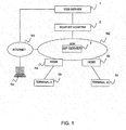
- FIG. 1 is an explanatory view showing a configuration example of a communication network according to a first embodiment.
- This communication network comprises a Web server 1, an SOAP-SIP adapter 2, a SIP server 3, and an Home Gateway (HGW) 4a, 4b, for example.
- the SIP server 3 is installed in an NGN N2, for example.
- the Web server 1 communicates with the SOAP-SIP adapter 2. Also, the Web server 1 communicates via a network such as internet N1 with a terminal 5a.
- the SOAP-SIP adapter 2 communicates via the NGN N2 and the HGW 4a with a terminal A5b.
- the SOAP-SIP adapter 2 and a terminal B5c have also the same configuration.
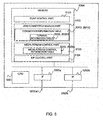
- FIG. 2 is an explanatory view showing a configuration example of the SOAP-SIP adapter 2 according to the first embodiment.
- the SOAP-SIP adapter 2 comprises a processor (hereinafter CPU) 2001, an interface (hereinafter IF) 2003a, 2003b, and a memory 2004, for example.
- the memory 2004 has an SOAP control part 2101, a 3PCC module part 2102, a media stream control part 2103, and a SIP control part 2104.
- the 3PCC module part 2102 has a session information table 2010, and the media stream control part 2103 has a media stream control information table 2040.
- the session information table 2010 has a call participant information table 2020 and a terminal information table 2030.
- the CPU 2001 performs each processing in the SOAP-SIP adapter 2.
- the SOAP control part 2101, the 3PCC module part 2102, the media stream control part 2103 and the SIP control part 2104 on the memory 2004 are performed by the CPU 2001.
- the IF 2003 is interface for making the communication via a line 2002 with the Web server 1 and the NGN N2.
- FIG. 3A is an explanatory view showing one example of the organization of the session information table 2010 in the SOAP-SIP adapter 2 according to the first embodiment.
- the session information table 2010 stores, associated with a session ID 2011, a session state 2012, a call participant state 2020, and the terminal information 2030, for example.
- the session ID 2011 is a session identifier corresponding to a connection request from the Web server 1.
- the session ID 2011 identifies the communication between the terminal A5b and the terminal B5c.
- the session state 2012 indicates the state of session designated by the session ID 2011.
- the session state 2012 stores an "Initial (initial state)", a "Connected (connected state)", or a "Terminated (terminated state)", for example.
- the call participant state 2020 corresponds to the call participant information table 2020.
- the details of the call participant information table 2020 will be described below.
- the terminal information 2030 corresponds to the terminal information table 2030.
- the terminal information 2030 is stored for each terminal. In an illustrated example, the terminal information (for Client A) 2030_A corresponding to the terminal A5b and the terminal information (for Client B) 2030_B corresponding to the terminal B5c are stored. The details of the terminal information table 2030 will be described below.
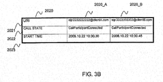
- FIG. 3B is an explanatory view showing one example of the organization of the call participant information table 2020 in the SOAP-SIP adapter 2 according to the first embodiment.
- the call participant information table 2020 stores, for each terminal, a URI 2021, a call state 2022 and a start time (clock) 2023, for example.
- the URI 2021 indicates a SIP-URI corresponding to each user.
- the call state 2022 indicates the state of session of the SIP between the SOAP-SIP adapter 2 and each terminal 5b, 5c.
- the call state 2022 stores a "Call Participant Initial (Initial state)", a "Call Participant Connected (connected state)” or a "Call Participant Terminated (terminated state)", for example.
- the start time 2023 indicates the time when the SOAP-SIP adapter 2 establishes the session of the SIP for each terminal 5b, 5c.
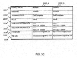
- FIG. 3C is an explanatory view showing one example of the organization of the terminal information table 2030 in the SOAP-SIP adapter 2 according to the first embodiment.
- the terminal information table 2030 stores the parameters for use in the SIP, for example.
- the terminal information table 2030 stores a handle value 2031, a session ID 2032, a terminal state 2033, a Role 2034, the send Session Description Protocol (SDP) information 2035, the recv SDP information 2036, a From URI 2037, and a To URI 2038, for example.
- SDP Session Description Protocol
- the handle value 2031 is the information for identifying the session of the SIP between the SOAP-SIP adapter 2 and the terminal 5b and the session of the SIP between the SOAP-SIP adapter 2 and the terminal B5c.
- the session ID 2032 corresponds to the session ID 2011 of the session information table 2010.
- the terminal state 2033 indicates the state till establishing the session between the SOAP-SIP adapter 2 and each terminal 5b, 5c.
- the terminal state 2033 accepts an "Initial (initial state)", a "Connect Wait (state waiting for a 'response')", a "Call Complete (state accepting the 'response' and establishing the session with the UA, a "Close Wait (state waiting for a 'disconnect complete notice')", and a "Closed (terminated state)", for example.
- the "Initial” and the "Connect Wait” correspond to the "Call Participant Initial" of the call state 2022 stored in the call participant information table 2020.
- the "Call Complete” and the "Close Wait” correspond to the "Call Participant Connected" of the call state 2022 stored in the call participant information table 2020.
- the "Close Wait” corresponds to the "Call Participant Terminated” of the call state 2022.
- the Role 2034 is the information indicating the call outgoing side or call incoming side.
- the send SDP information 2035 includes the IP address and the port number of the SOAP-SIP adapter 2, for example.
- the recv SDP information 2036 includes the IP address and the port number of the terminal A5b or terminal B5c, for example.
- the From URI 2037 indicates the sender URI of a SIP message sent by the SOAP-SIP adapter 2.
- the From URI 2037 is the SIP-URI of the SOAP-SIP adapter 2, for example.
- the To URI 2038 indicates the destination URI of SIP message sent by the SOAP-SIP adapter 2.
- the To URI 2038 is the SIP-URI of the terminal A5b or terminal B5c, for example.
- FIG. 3D is an explanatory view showing one example of the organization of the media stream control information table 2040 in the SOAP-SIP adapter 2 according to the first embodiment.
- the media stream control information table 2040 stores, associated with a session ID 2041, a media stream sending/receiving IP address 2042, a media stream sending/receiving port number 2043, a partner IP address (1) 2044, a partner port number (1) 2045, a partner IP address (2) 2046, and a partner port number (2) 2047, for example.
- the session ID 2041 corresponds to the session ID 2011 of the session information table 2010.
- the media stream sending/receiving IP address 2042 and the media stream sending/receiving port number 2043 are the IP address and the port number of the IF 2003 for use when the SOAP-SIP adapter 2 transfers the media stream.
- the pairs of the partner IP address (1) 2044 and the partner port number (1) 2045 and the partner IP address (2) 2046 and the partner port number (2) 2047 designate the destination of transferring the media stream. For example, in the case where the sender of the media stream corresponds to the partner IP address (1) 2044 and the partner port number (1) 2045, the media stream is transferred to the corresponding destination with the partner IP address (2) 2046 and the partner port number (2) 2047.
- the media stream is transferred to the corresponding destination with the partner IP address (2) 2044 and partner port number (1) 2045 in the same manner.
- the partner IP address (1) 2044 and the partner port number (1) 2045 designate the IP address and the port number of the terminal A5b
- the partner IP address (2) 2046 and the partner port number (2) 2047 designate the IP address and the port number of the terminal B5c.
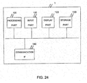
- FIG. 24 is a configuration diagram of the web server 1.
- the web server 1 comprises a processing part 100, an input part 110, a display part 120, a storage part 130, and a communication interface 140, for example.
- the input part 110 receives the input of a Session ID or the input of a user identifier, for example.
- the display part 120 displays the user identifier and the SIP-URI.
- the storage part 130 stores the received Session ID, for example.
- the communication interface 140 is the interface for communicating with the SOAP-SIP adapter 2, for example.
- the processing part 100 performs various kinds of processing in the web server 1.
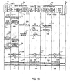
- FIG. 12 is a sequence chart for explaining a 3PCC service procedure according to the first embodiment.
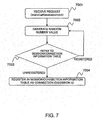
- FIG. 7 is a flowchart for explaining the generation of a session ID/connection ID in the SOAP-SIP adapter.
- the connection ID is used in the second embodiment.
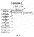
- FIG. 8 is a flowchart for explaining the operation in receiving a call start request in the SOAP-SIP adapter 2 according to the first embodiment.
- the flow up to the 3PCC service is the following (a) to (c).
- RBT Ringing Back Tone
- the data from the first connection terminal A5b is received by the SOAP-SIP adapter 2 and transferred to the second connection terminal B5c.
- the data from the second connection terminal B5c is received by the SOAP-SIP adapter 2 and transferred to the first connection terminal A5b.
- the SOAP-SIP adapter 2 creates the media stream control information table 2040 for implementing the above transfer.
- the user of the third party logs into the Web server 1 by operating the terminal 5a.
- the Web server 1 inputs the user identifiers of the users to communicate (e.g., user names of two parties corresponding to the terminal A5b and the terminal B5c) from the terminal 5a.
- the Web server 1 may select the users of two parties to communicate through the operation of the user in accordance with the screen displayed for the terminal 5a that logs in.
- the Web server 1 sends an SOAP make Call Session Request (connection request) to the SOAP-SIP adapter 2 (S1).
- the SOAP make Call Session Request includes the SIP-URI corresponding to each of the user of two parties to be connected.
- the Web server 1 acquires the SIP-URI corresponding to the input user identifier, because the user identifier and the SIP-URI of the user are associated and prestored.
- the Web sever 1 generates the SOAP make Call Session Request including the acquired SIP-URI, and sends it to the SOAP-SIP adapter 2.
- the SOAP-SIP adapter 2 starts the connection to each terminal 5b, 5c corresponding to the SIP-URI included in the received SOAP make Call Session Request, and sends an SOAP make Call Session Response including the session ID generated in the SOAP-SIP adapter 2 (S2 to S15).
- S2 to S15 The detailed operation of the steps S2 to S15 in the SOAP-SIP adapter 2 will be described below.
- the SOAP control part 2101 of the SOAP-SIP adapter 2 receives the SOAP make Call Session Request, and sends a connection request to the 3PCC module part 2102 (S2).
- This connection request can be generated in accordance with an appropriate protocol for use in the SOAP-SIP adapter 2, based on the received SOAP make Call Session Request, for example, and includes the SIP-URI within the SOAP make Call Session Request.
- the 3PCC module part 2102 receives the connection request (7001, 8001), and generates a session ID (8002). Referring to FIG. 7 , the generation of the session ID will be described below.
- the 3PCC module part 2102 receives the connection request and generates the random number value (7002).
- the 3PCC module part 2102 judges whether or not the generated random number value is already registered in the session ID 2011 of the session information table 2010 (7003). If the generated random number value is already registered (i.e., already used), the 3PCC module part 2102 returns to step 7002 to repeat the subsequent processing. On the other hand, if the generated random number value is not registered, the 3PCC module part 2102 stores the generated session ID in the session information table 2010 (7004). Further, the 3PCC module part 2102 sets the session state 2012 of the session information table 2010 to "Initial (initial state)".
- the 3PCC module part 2102 stores the SIP-URI included in the received connection request in the call participant information table 2020.
- the SIP-URI see 2020_A
- the SIP-URI see 2020_B
- the 3PCC module part 2102 sets the call state 2022 corresponding to each terminal 5b, 5c of the call participant information table 2020 to "Call Participant Initial (initial state)".
- the 3PCC module part 2102 stores the terminal information of the terminal A5b and the terminal B5c. More specifically, the 3PCC module part 2102 stores the generated session ID in the terminal information table 2030, associated with each terminal 5b, 5c. Also, the 3PCC module part 2102 stores each SIP-URI included in the received connection request in the To URI 2038 corresponding to each terminal 5b, 5c of the terminal information table 2030. The 3PCC module part 2102 sets the terminal state 2032 corresponding to each terminal 5b, 5c of the terminal information table 2030 to "Initial (initial state)".
- the 3PCC module part 2102 sets the information indicating the call outgoing side or call incoming side to the Role 2033 corresponding to each terminal 5b, 5c of the terminal information table 2030. It can be appropriately decided which of the terminals 5b and 5c is the call outgoing side. Also, the 3PCC module part 2102 stores the IP address and the port number of the SOAP-SIP adapter 2 in the send SDP information 2035 of the terminal information table 2030. Also, the 3PCC module part 2102 stores the SIP-URI of the SOAP-SIP adapter 2 in the From URI 2037 corresponding to each terminal 5b, 5c of the terminal information table 2030. The SIP-URI, the IP address and the port number of the SOAP-SIP adapter 2 are prestored in the appropriate storage part.
- the 3PCC module part 2102 generates a connection request success response, and sends it to the SOAP control part 2101 (S3, 8011).
- the connection request success response includes the generated session ID.
- the SOAP control part 2101 receives the connection request success response, and sends an SOAP make Call Session Response (connection request success response) to the Web server 1 (S4, 8012).
- the SOAP make Call Session Response includes the generated session ID, and is generated in accordance with the SOAP, based on the received connection request success response.
- the Web server 1 receives the SOAP make Call Session Response, and stores the session ID included in the received SOAP make Call Session Response in the appropriate storage part.
- the 3PCC module part 2102 If the generation of the session ID fails at step 8002, the 3PCC module part 2102 generates a connection request failure response (error response message) (8013), and sends it to the SOAP control part 2101.
- the SOAP control part 2101 receives the connection request failure response, and sends an SOAP make Call Session Response indicating the connection request failure to the Web server 1 (8012).
- the 3PCC module part 2102 acquires a media stream control/transfer port (8003).
- the 3PCC module part 2102 sends a call outgoing request (A) for the terminal A5b to the SIP control part 2104 (S5, 8004).
- the 3PCC module part 2102 sends the call outgoing request including the send SDP information 2035, the From URI 2037 and the To URI 2038 corresponding to the terminal A5b stored in the terminal information table 2030 to the SIP control part 2104.
- the 3PCC module part 2102 stores the current time as one example in the start time 2023 corresponding to the terminal A5b of the call participant information table 2020. In an example of the call participant information table 2020 as shown in FIG. 3B , "2008.10.22 10:30.30" is stored.
- the start time 2023 is not limited to the current time, but may be the appropriate time indicating the start of session with the terminal A5b.
- the SIP control part 2104 sends an INVITE message (A) to the terminal A5b in accordance with the To URI included in the call outgoing request (A) (S6).
- the INVITE message (A) includes at least the send SDP information, the From URI, and the To URI included in the received call outgoing request, for example. Also, the SIP control part 2104 generates a handle value identifying the session with the terminal A5b.
- the terminal A5b receives the INVITE message (A), and stores the IP address and the port number of the SOAP-SIP adapter 2 included in the send SDP information of the received INVITE message (A) in the appropriate storage part.
- the stored IP address and port number are used in sending the media stream, for example.
- the terminal A5b generates the recv SDP information including its own IP address and port number and sends a 200 OK (A) of the SIP including the generated SDP information to the SOAP-SIP adapter 2 (S7).
- the SIP control part 2104 of the SOAP-SIP adapter 2 receives the 200 OK (A) and sends an ACK (A) of the SIP to the terminal A5b (S8).
- the SIP control part 2104 sends a response notice (A) to the 3PCC module part 2102 (S9, 8005).
- the response notice (A) includes the handle value generated at step S6 and the recv SDP information of the terminal A5b included in the 200 OK received at step S7, for example.
- the 3PCC module part 2102 stores, associated with the terminal A5b, the handle value and the recv SDP information included in the received response notice (A) in the terminal information table 2030.
- the handle value may be stored at an appropriate timing from step S6 to step S8.
- the 3PCC module part 2102 updates the terminal state 2033 corresponding to the terminal A5b of the terminal information table 2030 to "Call Complete (session established state)".
- the 3PCC module part 2102 updates the call state 2022 corresponding to the terminal A5b of the call participant information table 2020 to "Call Participant Connected (connected state)".
- the terminal state 2033 may be appropriately updated upon sending or receiving the SIP message (e.g., 200 OK and so on), for example.
- the 3PCC module part 2102 sends the generated session ID, the IP address and port number of the SOAP-SIP adapter 2, and the IP address and port number of the terminal A5b included in the received recv SDP information to the media stream control part 2103.
- the media stream control part 2103 stores the received information in the media stream control information table 2040.
- the media stream control part 2103 stores the received IP address and port number of the SOAP-SIP adapter 2 at the media stream sending/receiving IP address 2042 and the media stream sending/receiving port number 2043, and stores the received IP address and port number of the terminal A5b at the partner IP address (1) 2044 and the partner port number (1) 2045.
- the media stream control part 2103 stores the received session ID.
- the 3PCC module part 2102 sends a pseudo RBT sending request to the media stream control part 2103 (S101).
- the media stream control part 2103 receives the pseudo RBT sending request, and sends the pseudo RBT to the terminal A5b in accordance with a Real-time Transport Protocol (RTP), for example (S10, 8006).
- RTP Real-time Transport Protocol
- the media stream control part 2103 may use an announcement of calling the partner or appropriate music, for example, as the pseudo RBT.
- the terminal A5b is prevented from being in silent state at the stage where the establishment of session with the terminal A5b is completed and the establishment of session with the terminal B5c is started. This pseudo RBT can continue to be sent until a stop request is made as will be described later.
- the 3PCC module part 2102 sends a call outgoing request (B) for the terminal B5c to the SIP control part 2104 (S11, 8007).
- the 3PCC module part 2102 sends the call outgoing request including the send SDP information 2035, the From URI 2037 and the To URI 2038 corresponding to the terminal B5c stored in the terminal information table 2030 to the SIP control part 2104.
- the 3PCC module part 2102 stores the current time in the start time 2023 corresponding to the terminal B5c of the call participant information table 2020. In an example of the call participant information table 2020 as shown in FIG. 3B , "2008.10.22 10:30.45" is stored.
- the SIP control part 2104 sends an INVITE message (B) to the terminal B5c in accordance with the To URI included in the call outgoing request (A) (S12).
- the INVITE message (B) includes at least the send SDP information, the From URI, and the To URI included in the received call outgoing request, for example. Also, the SIP control part 2104 generates a handle value identifying the session with the terminal B5c.
- the terminal B5c receives the INVITE message (B), and stores the IP address and port number of the SOAP-SIP adapter 2 included in the send SDP information of the received INVITE message (B) in the appropriate storage part. Also, the terminal B5c generates the recv SDP information including its own IP address and port number and sends a 200 OK (B) including the generated recv SDP information to the SOAP-SIP adapter 2 (S13).
- the SIP control part 2104 of the SOAP-SIP adapter 2 receives the 200 OK (B) and sends an ACK (B) to the terminal B5c (S14).
- the SIP control part 2104 sends a response notice (B) to the 3PCC module part 2102 (S15, 8008).
- the response notice (B) includes the handle value generated at step S12 and the recv SDP information of the terminal B5c included in the 200 OK received at step S13, for example.
- the 3PCC module part 2102 stores the handle value and the recv SDP information included in the received response notice (B) in the terminal information table 2030, associated with the terminal B5c.
- the handle value may be stored at an appropriate timing from step S12 to step S14.
- the 3PCC module part 2102 updates the terminal state 2033 corresponding to the terminal B5c of the terminal information table 2030 to "Call Complete (session established state)".
- the 3PCC module part 2102 updates the call state 2022 corresponding to the terminal B5c of the call participant information table 2020 to "Call Participant Connected (connected state)". Also, the 3PCC module part 2102 updates the session state of the session information table 2010 to "Connected (connected state)".
- the 3PCC module part 2102 sends the session ID, and the IP address and port number of the terminal B5c included in the received recv SDP information to the media stream control part 2103.
- the media stream control part 2103 stores, associated with the received session ID, the IP address and port number of the terminal B5c in the partner IP address (2) 2046 and the partner port number (2) 2047 of the media stream control information table 2040.
- the 3PCC module part 2102 sends a pseudo RBT stop request to the media stream control part 2103 (S102, 8009).
- the media stream control part 2103 stops sending the pseudo RBT in accordance with the pseudo RBT stop request.
- the SOAP-SIP adapter 2 starts to transfer the media stream between the terminal A5b and the terminal B5c (8010).
- the terminal A5b sends the media stream to the SOAP-SIP adapter 2 in accordance with the RTP (S16).
- the terminal A5b sets the IP address and port number of the SOAP-SIP adapter 2 stored at step S6 to the destination, and sets its own IP address and port number to the sender.
- the media stream control part 2103 of the SOAP-SIP adapter 2 transfers the received media stream to the terminal B5c by referring to the media stream control information table 2040 (S17). For example, the media stream control part 2103 acquires the corresponding partner IP address and port number by referring to the media stream control information table 2040 based on the sender IP address and port number of the received media stream.
- the sender IP address and port number of the received media stream are the IP address (10.0.2.1) and port number (20000) of the terminal A5b, and the corresponding partner IP address (2) 2046 (10.0.2.2) and port number (2) 2047 (30000) are acquired.
- the media stream control part 2103 transfers the received media stream to the terminal B5c in accordance with the acquired IP address and port number.
- the terminal B5c sends the media stream to the SOAP-SIP adapter 2 in accordance with the RTP (S18).
- the terminal B5c sets the IP address and port number of the SOAP-SIP adapter 2 stored at step S12 to the destination, and sets its own IP address and port number to the sender.
- the media stream control part 2103 of the SOAP-SIP adapter 2 transfers the received media stream to the terminal A5b by referring to the media stream control information table 2040 (S19).
- the sender IP address and port number of the received media stream are the IP address (10.0.2.2) and port number (30000) of the terminal B5c, and the corresponding partner IP address (1) 2044 (10.0.2.1) and port number (1) 2045 (20000) are acquired.
- the media stream control part 2103 transfers the received data stream to the terminal A5b in accordance with the acquired IP address and port number.
- the IP address establishing the signaling channel and the IP address establishing the data channel become the same, whereby the data from the terminal A5b is received by the SOAP-SIP adapter 2 and transferred to the terminal B5c, and the data from the terminal B5c is received by the SOAP-SIP adapter 2 and transferred to the terminal A5b, so that the 3PCC service on the NGN with the assured communication quality is enabled.
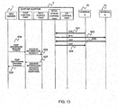
- FIG. 13 is a sequence chart (2) for explaining the 3PCC service procedure according to the first embodiment.
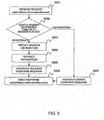
- FIG. 9 is a flowchart for explaining the operation in receiving a call information (session information) request in the SOAP-SIP adapter 2 according to the first embodiment.
- the Web server 1 can acquire the information corresponding to the designated session ID.
- the processings of steps S21 to S24 in FIG. 13 correspond to the processings of steps S16 to S19 as described above.
- the Web server 1 sends an SOAP get Call Session Information Request (session information request, call information request) to the SOAP-SIP adapter 2 (S25).
- the SOAP get Call Session Information Request includes the session ID of the call information to be acquired. More specifically, the Web sever 1 generates the SOAP get Call Session Information Request including the session ID stored at step S4 as described above, and sends it to the SOAP-SIP adapter 2.
- the Web server 1 may select the session ID of the call information to be acquired from the session ID stored at step S4 as described above, based on the user operation from the terminal 5a.
- the SOAP-SIP adapter 2 searches the session information table 2010 held in the SOAP-SIP adapter 2 with the session ID included in the SOAP get Call Session Information Request as the key, and sends the SOAP get Call Session Information Response including the table information of the matched session ID 2011 (S26 to S28).
- the detailed operation of steps S26 to S28 in the SOAP-SIP adapter 2 will be described below.
- the SOAP control part 2101 of the SOAP-SIP adapter 2 receives the SOAP get Call Session Information Request, and sends a session information request to the 3PCC module part 2102 (S26).
- This session information request includes the session ID in the SOAP get Call Session Information Request.
- the 3PCC module part 2102 receives the session information request (9001), and searches the session information table 2010 for the session ID 2011 based on the session ID included in the received session information request (9002). If the session ID included in the received session information request is already registered in the session information table 2010, the session information corresponding to the pertinent session ID 2011 is specified (9003).
- the 3PCC module part 2102 acquires the URI 2021 and the call state 2022 corresponding to each terminal 5b, 5c, for example, by referring to the call participant information table (call participant state) 2020 corresponding to the pertinent session ID 2011 (9004). Further, the 3PCC module part 2102 acquires the recv SDP information 2036 of each terminal from the terminal information (for Client A) 2030_A and the terminal information (for Client B) 2030_B corresponding to the pertinent session ID 2011, for example.
- the 3PCC module part 2102 generates a session information request success response including the session ID 2011, the acquired URI 2021, the call state 2022 and the recv SDP information 2036 (9005), and sends the generated session information request success response to the SOAP control part 2101 (S27).
- the SOAP control part 2101 receives the session information request success response, and sends an SOAP get Call Session Information Response (session information request success response) to the Web server 1 (S28, 9006).
- the SOAP get Call Session Information Response includes the session ID, the URI, the call state and the recv SDP information in the received session information request success response and is generates in accordance with the SOAP.
- the 3PCC module part 2102 If the session ID included in the received session information request is not registered at step 9002, the 3PCC module part 2102 generates a session information request failure response (error response message) (9007), and sends the generated session information request failure response to the SOAP control part 2101.
- the SOAP control part 2101 receives the session information request failure response, and sends the SOAP get Call Session Information Response indicating the session information request failure to the Web server 1 (9006).
- the Web server 1 receives the SOAP get Call Session Information Response, and can confirm the session state as to whether or not the requested communication comes into existence by referring to the call state included in the received SOAP get Call Session Information Response, for example. For example, if the call is terminated from the terminal, the call state becomes "Call Participant Terminated (terminated state)", whereby the Web server 1 can judge that the call is terminated from the terminal A5b or terminal B5c. Also, for example, if the call state is not normal, the Web server 1 may stop the communication using an SOAP end Call Session Request as will be described later.
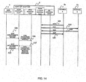
- FIG. 14 is a sequence chart (3) for explaining the 3PCC service procedure according to the first embodiment.
- FIG. 10 is a flowchart for explaining the operation in receiving a call participant information request in the SOAP-SIP adapter 2 according to the first embodiment.
- the Web server 1 can acquire the user information corresponding to the designated SIP-URI.
- the processings of steps S31 to S34 in FIG. 14 correspond to the processings of steps S16 to S19 as described above.
- the Web server 1 sends an SOAP get Call Participants Information Request (call participant information request) to the SOAP-SIP adapter 2 (S35).
- the SOAP get Call Participants Information Request includes the session ID and URI of the call participant information to be acquired.
- the Web sever 1 generates the SOAP get Call Session Information Request including the session ID stored at step S4 as described above and the SIP-URI of the desired call participant, and sends it to the SOAP-SIP adapter 2.
- the Web server 1 may select the session ID and the user identifier (e.g., user name corresponding to the terminal A5b, terminal B5c) of the call information to be acquired based on the user operation from the terminal 5a.
- the Web server 1 can acquire the SIP-URI corresponding to the input user identifier, because the user identifier and the SIP-URI of the user are associated and prestored as above described.
- the SOAP-SIP adapter 2 searches the session information table 2010 held in the SOAP-SIP adapter 2 with the session ID included in the SOAP get Call Participants Information Request as the key, and specifies the table information of the matched session ID 2011. Further, the SOAP-SIP adapter 2 searches the call participant information table 2020 with the SIP-URI included in the SOAP get Call Participants Information Request as the key, and sends the SOAP get Call Participants Information Response including the table information corresponding to the matched SIP-URI 2021 (S36 to S38). The operation of steps S36 to S38 in the SOAP-SIP adapter 2 will be described below.
- the SOAP control part 2101 of the SOAP-SIP adapter 2 receives the SOAP get Call Participants Information Request, and sends a call participant information request to the 3PCC module part 2102 (S36).
- This call participant information request includes the session ID and the SIP-URI in the SOAP get Call Participants Information Request.
- the 3PCC module part 2102 receives the call participant information request (1001), and searches the session information table 2010 for the session ID 2011, based on the session ID included in the received call participant information request (1002). If the session ID included in the received call participant information request is already registered in the session information table 2010, the session information is specified by the pertinent session ID 2011 (1003).
- the 3PCC module part 2102 searches the call participant information table (call participant state) 2020 corresponding to the pertinent session ID 2011 for the URI 2021, based on the SIP-URI included in the received call participant information request (1004). If the SIP-URI included in the received call participant information request is already registered, the 3PCC module part 2102 acquires the call state 2022 corresponding to the pertinent URI 2021 (1005). Also, the 3PCC module part 2102 acquires the corresponding recv SDP information 2036 by referring to the To URI 2038 of the terminal information table 2030, based on the SIP-URI included in the received call participant information request.
- the 3PCC module part 2102 generates a call participant information request success response including the URI 2021, the acquired call state 2022 and the recv SDP information 2036 (1006), and sends the generated call participant information request success response to the SOAP control part 2101 (S37).
- the SOAP control part 2101 receives the call participant information request success response, and sends an SOAP get Call Participants Information Response (call participant information request success response) to the Web server 1 (S38, 1007).
- the SOAP get Call Participants Information Response includes the URI, the call state and the recv SDP information in the received call participant information request success response and is generated in accordance with the SOAP.
- the 3PCC module part 2102 If the session ID included in the received call participant information request is not registered at step 1002, and the SIP-URI included in the received call participant information request is not registered at step 1004, the 3PCC module part 2102 generates a call participant information request failure response (error response message) (1008), and sends the generated call participant information request failure response to the SOAP control part 2101.
- the SOAP control part 2101 receives the call participant information request failure response, and sends the SOAP get Call Participants Information Response indicating the call participant information request failure to the Web server 1 (1007).
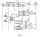
- FIG. 15 is a sequence chart (4) for explaining the 3PCC service procedure according to the first embodiment.
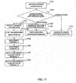
- FIG. 11 is a flowchart for explaining the operation in receiving a call end request in the SOAP-SIP adapter 2 according to the first embodiment.
- steps S41 to S44 in FIG. 15 correspond to the processings of steps S16 to S19 as described above.
- the Web server 1 sends an SOAP end Call Session Request (call end request) to the SOAP-SIP adapter 2 (S45).
- the SOAP end Call Session Request includes the session ID of the call to be ended. More specifically, the Web sever 1 generates the SOAP end Call Session Request including the session ID stored at step S4 as described above, and sends it to the SOAP-SIP adapter 2.
- the Web server 1 may select the session ID of the call to be ended from the session ID stored at step S4 as described above, based on the user operation from the terminal 5a.
- the SOAP-SIP adapter 2 searches the session information table 2010 held in the SOAP-SIP adapter 2 with the session ID included in the SOAP end Call Session Request as the key, specifies the terminals 5b, 5c to be disconnected from the table information of the matched session ID 2011 and disconnects them (S46 to S56).
- the detailed operation of steps S46 to S56 in the SOAP-SIP adapter 2 will be described below.
- the SOAP control part 2101 of the SOAP-SIP adapter 2 receives the SOAP end Call Session Request (call end request), and sends the call end request to the 3PCC module part 2102 (S46).
- This call end request includes the session ID in the SOAP end Call Session Request.
- the 3PCC module part 2102 receives the call end request (1101), and searches the session information table 2010 for the session ID 2011, based on the session ID included in the received call end request (1102).
- the 3PCC module part 2102 If the session ID included in the received call end request is already registered in the session information table 2010, the 3PCC module part 2102 generates a call end request success response (1109), and sends the generated call end request success response to the SOAP control part 2101 (S47).
- the SOAP control part 2101 receives the call end request success response, and sends an SOAP end Call Session Response (call end request success response) to the Web server 1 (S48, 1110).
- SOAP end Call Session Response For the Soap end Call Session Response, only the success response may be sent.
- the session information is specified by the pertinent session ID 2011 to specify the two parties (here the terminal A5b, terminal B5c) during the telephone communication (1103).
- the 3PCC module part 2102 acquires the SIP-URI 2021 of each terminal A5b, terminal B5c by referring to the call participant information table 2020 corresponding to the session ID included in the received call end request.
- the media stream control part 2103 stops the transfer of media stream (1104).
- a media stream transfer stop request may be sent from the 3PCC module part 2102 to the media stream control part 2103.
- the 3PCC module part 2102 sends a disconnect request (A) including the acquired SIP-URI to the SIP control part 2104 in accordance with one of the acquired SIP-URIs (S49, 1105).
- the SIP control part 2104 receives the disconnect request (A), and sends a BYE message (A) of the SIP to the terminal A5b with the SIP-URI included in the received disconnect request (A) as the To URI (S50).
- the 3PCC module part 2102 sends a disconnect request (B) including the acquired SIP-URI to the SIP control part 2104 in accordance with the other acquired SIP-URI (S51, 1106).
- the SIP control part 2104 receives the disconnect request (B), and sends a BYE message (B) to the terminal B5c with the SIP-URI included in the received disconnect request (B) as the To URI (S52).
- the terminal A5b sends a 200 OK (A) for the BYE message (A) received at step S50 to the SOAP-SIP adapter 2 (S53).
- the SIP control part 2104 of the SOAP-SIP adapter 2 receives the 200 OK (A), and sends a disconnect complete notice (A) to the 3PCC module part 2102 (S54, 1107).
- the terminal B5c sends a 200 OK (B) for the BYE message (B) received at step S52 to the SOAP-SIP adapter 2 (S55).
- the SIP control part 2104 of the SOAP-SIP adapter 2 receives the 200 OK (B), and sends a disconnect complete notice (B) to the 3PCC module part 2102 (S56, 1108).
- the 3PCC module part 2102 If the session ID included in the received call end request is not registered at step 1102, the 3PCC module part 2102 generates a call end request failure response (error response message) (1111), and sends the generated call end request failure response to the SOAP control part 2101.
- the SOAP control part 2101 receives the call end request failure response, and sends the SOAP end Call Session Response indicating the call end request failure to the Web server 1 (1110).
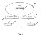
- FIG. 4 is an explanatory view showing a configuration example of a communication network according to a second embodiment.
- the communication network (system) of this embodiment comprises a SIP server 3 and an SOAP-SIP adapter 6a, 6b, for example.
- the SIP server 3 is installed in an NGN N2.
- the SOAP-SIP adapter 6a communicates via the NGN N2 with the SOAP-SIP adapter 6b. Also, a terminal 7a and a terminal 7b communicate via the SOAP-SIP adapter 6a and the SOAP-SIP adapter 6b. It is predetermined which SOAP-SIP adapter 6 the terminal 7 is connected to, in which the SOAP-SIP adapter 6a and the terminal A7a correspond one to one, and the SOAP-SIP adapter 6b and the terminal B7b also correspond one to one. For example, to communicate with the terminal B7b, it is possible to communicate with the terminal B7b if the SOAP-SIP adapter 6b is designated. Also, the SOAP-SIP adapter 6 and the terminal 7 may correspond one to many, and the correspondence between the SOAP-SIP adapter 6 and the terminal 7 to be connected may be stored in an appropriate device.
- FIG. 5 is an explanatory view showing a configuration example of the SOAP-SIP adapter 6 according to the second embodiment.
- the SOAP-SIP adapter 6 of this embodiment comprises an NGN connection module part 5102, instead of the 3PCC module part 2102 of the first embodiment, for example.
- the NGN connection module part 5102 has a connection information table 5010, which has a terminal information table 5020.
- a CPU 5001, an IF 5003a, 5003b, an SOAP control part 5101, a media stream control part 5103, and a SIP control part 5104 are the same as those of the first embodiment.
- FIG. 6A is an explanatory view showing one example of the organization of the connection information table 5010 in the SOAP-SIP adapter 6a according to the second embodiment.
- connection information table 5010 stores, associated with a connection ID 5011, a connection state 5012 and the terminal information 5013, for example.
- the connection ID 5011 is the information identifying the connection corresponding to the connection request from the terminal 7. For example, the connection in the Transmission Control Protocol (TCP) is identified.
- the connection ID 5011 is generated for each SOAP-SIP adapter 6.
- the connection state 5012 indicates the state of connection, corresponds to the session state 2012 of the first embodiment, for example, and stores the same state.
- the terminal information 5013 corresponds to the terminal information table 5020.
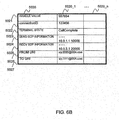
- FIG. 6B is an explanatory view showing one example of the organization of the terminal information table 5020 in the SOAP-SIP adapter 6a according to the second embodiment.
- the terminal information table 5020 stores a handle value 5021, a connection ID 5022, a terminal state 5023, the send SDP information 5024, the recv SDP information 5025, a From URI 5026 and a To URI 5027, for example.
- the handle value 5021 is the information identifying the session of SIP between the SOAP-SIP adapter 6a and the SOAP-SIP adapter 6b.
- the connection ID 5022 corresponds to the connection ID 5011 in the connection information table 5010 as described above.
- the terminal state 5023 indicates the state of session between the SOAP-SIP adapter 6a and the SOAP-SIP adapter 6b.
- the terminal state 5023 is stored in the same state as the terminal state 2033 of the first embodiment, for example.
- the send SDP information 5024 includes the IP address and the port number of the SOAP-SIP adapter 6 itself, for example. In an example of the SOAP-SIP adapter 6a as shown in FIG.
- the recv SDP information 5025 includes the IP address and the port number of the SOAP-SIP adapter 6 to be connected, for example. In the example of FIG. 6B , it includes the IP address (10.0.2.1) and the port number (20000) of the SOAP-SIP adapter 6b.
- the From URI 5026 indicates the SIP-URI of the SOAP-SIP adapter 6 itself, for example. In the example of FIG. 6B , it indicates the SIP-URI of the SOAP-SIP adapter 6a.
- the To URI 5027 indicates the SIP-URI of the SOAP-SIP adapter 6 to be connected, for example. In the example of FIG. 6B , it indicates the SIP-URI of the SOAP-SIP adapter 6b.
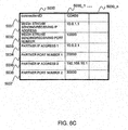
- FIG. 6C is an explanatory view showing one example of the organization of the media stream control information table 5030 in the SOAP-SIP adapter 6a according to the second embodiment.
- the media stream control information table 5030 of this embodiment stores a connection ID 5031, instead of the session ID 2041 of the first embodiment, for example.
- the connection ID 5031 corresponds to the connection ID 5011 of the connection information table 5010.
- the other items including a media stream sending/receiving IP address 5032, a media stream sending/receiving port number 5033, a partner IP address (1) 5034, a partner port number (1) 5035, a partner IP address (2) 5036, and a partner port number (2) 5037 are the same as those of the first embodiment.
- the partner IP address (1) 5034 and the partner port number (1) 5035 store the IP address and the port number of the SOAP-SIP adapter 6b
- the partner IP address (2) 5036 and the partner port number (2) 5037 store the IP address and the port number of the terminal A7a.
- the media stream sending/receiving IP address 5032 and the media stream sending/receiving port number 5033 store the IP address and the port number of the SOAP-SIP adapter 6a as in the first embodiment.
- FIG. 21A is an explanatory view showing one example of the organization of a connection information table 6010 in the SOAP-SIP adapter 6b according to the second embodiment.
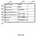
- FIG. 21B is an explanatory view showing one example of the organization of a terminal information table 6020 in the SOAP-SIP adapter 6b according to the second embodiment.
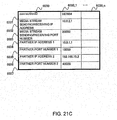
- FIG. 21C is an explanatory view showing one example of the organization of a media stream control information table 6030 in the SOAP-SIP adapter 6b according to the second embodiment.
- each table 6010, 6020, 6030 in the SOAP-SIP adapter 6b is the same as that of each table 5010, 5020, 5030 in the SOAP-SIP adapter 6a as described above.
- the IP address and the port number of the SOAP-SIP adapter 6b are stored in the send SDP information 6024, and the IP address and the port number of the SOAP-SIP adapter 6a to be connected is stored in the recv SDP information 6025.
- a From URI 6026 indicates the SIP-URI of the SOAP-SIP adapter 6b
- a To URI 6027 indicates the SIP-URI of the SOAP-SIP adapter 6a.
- a partner IP address (1) 6034 and a partner port number (1) 6035 store the IP address and the port number of the SOAP-SIP adapter 6a
- a partner IP address (2) 6036 and a partner port number (2) 6037 store the IP address and the port number of the terminal B7b.
- a media stream sending/receiving IP address 6032 and a media stream sending/receiving port number 6033 store the IP address and the port number of the SOAP-SIP adapter 6b.
- FIG. 19 is a sequence chart (1) for explaining an NGN connection service procedure according to the second embodiment.
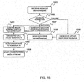
- FIG. 16 is a flowchart for explaining the operation in receiving a connection start request in the SOAP-SIP adapter 6 according to the second embodiment.
- FIG. 22 is a flowchart for explaining the operation in receiving a call incoming notice in the SOAP-SIP adapter 6 according to the second embodiment.
- FIG. 17 is a flowchart for explaining the operation in receiving a connection information request in the SOAP-SIP adapter 6 according to the second embodiment.
- the terminal A7a connected to the SOAP-SIP adapter 6a opens (breaks) a queue port for the SOAP-SIP adapter 6a at the start up, for example. Thereby, sending and receiving the data between the terminal A7a and the SOAP-SIP adapter 6a is enabled. At this time, the SOAP-SIP adapter 6a receives the IP address and port number of the terminal A7a, and stores the received IP address and port number of the terminal A7a in the appropriate storage part.
- the terminal B7b and the SOAP-SIP adapter 6b have also the same configuration.
- the terminal 7 is not limited to the above example, but may open the queue port at an appropriate timing.
- the terminal A7a sends an SOAP connect Request (connection request) to the SOAP-SIP adapter 6a (S61).
- the SOAP connect Request includes the SIP-URI of the SOAP-SIP adapter 6b corresponding to the terminal B7b to be connected.
- the terminal A7a may select the user identifier of the user or the SIP-URI of the SOAP-SIP adapter 6 to be connected from the appropriate input part, based on the user operation.
- the terminal A7a may specify the SIP-URI of the SOAP-SIP adapter 6 corresponding to the input user identifier, because the user identifier and the SIP-URI of the SOAP-SIP adapter 6 to which the terminal 7 of the user is connected are associated and prestored.
- a Web server in which the user identifier and the SIP-URI of the SOAP-SIP adapter 6 to which the user terminal 7 is connected are associated and prestored may be installed, and the Web server may return the SIP-URI of the SOAP-SIP adapter 6 corresponding to the user identifier selected at the terminal A7a.
- the SOAP control part 5101a of the SOAP-SIP adapter 6a receives the SOAP connect Request, and sends a connection request (B) to the NGN connection module part 5102a of the SOAP-SIP adapter 6a (S62).
- This connection request (B) includes the SIP-URI in the SOAP connect Request.
- the SOAP-SIP adapter 6a starts the connection to this SIP-URI.
- the NGN connection module part 5102a receives the connection request (B) (1601), and generates the connection ID (1602).
- the generation of the connection ID is the same as in FIG. 7 and its description of the first embodiment. Referring to FIGs. 6A and 6B , this embodiment will be described below, although the explanation is partially duplicated with that of FIG. 7 .
- the NGN connection module part 5102a stores the generated connection ID in the connection information table 5010 and the terminal information table 5020.
- the NGN connection module part 5102a sets the connection state 5012 of the connection information table 5010 to "Initial (initial state)". Further, the NGN connection module part 5102a stores the SIP-URI included in the received connection request (B) in the To URI 5027 of the terminal information table 5020.
- the NGN connection module part 5102a sets the terminal state 5023 of the terminal information table 5020 to "Initial (initial state)".
- the NGN connection module part 5102a stores the send SDP information 5024 including the IP address and the port number of the SOAP-SIP adapter 6a in the terminal information table 5020.
- the NGN connection module part 5102a stores the SIP-URI of the SOAP-SIP adapter 6a in the From URI 5026 of the terminal information table 5020.
- the SIP-URI, the IP address and the port number of the SOAP-SIP adapter 6a are prestored in the appropriate storage part.
- the NGN connection module part 5102a generates a connection success response (B) (1607), and sends the generated connection success response (B) to the SOAP control part 5101a (S63).
- the connection success response (B) includes the generated connection ID.
- the SOAP control part 5101a receives the connection success response (B), and sends an SOAP connect Response (connection success response) to the terminal A7a (S64, 1608).
- the SOAP connect Response includes the connection ID in the received connection success response (B), and is generated in accordance with the SOAP.
- the terminal A7a receives the SOAP connect Response, and stores the connection ID included in the received SOAP connect Response in the appropriate storage part.
- the NGN connection module part 5102a If the generation of the connection ID fails at step 1602, the NGN connection module part 5102a generates a connection request failure response (error response message) (1609), and sends it to the SOAP control part 5101a.
- the SOAP control part 5101a receives the connection request failure response, and sends the SOAP connect Response indicating the connection request failure to the terminal A7a (1608).
- the SOAP-SIP adapter 6a establishes the session with the SOAP-SIP adapter 6b.
- the NGN connection module part 5102a acquires a media stream control transfer port (1603).
- the NGN connection module part 5102a sends a call outgoing request (B) to the SIP control part 5104a of the SOAP-SIP adapter 6a (S65, 1604).
- the call outgoing request (B) includes the send SDP information 5024, the From URI 5026 and the To URI 5027 stored in the terminal information table 5020.
- the SIP control part 5104a receives the call outgoing request (B), and sends an INVITE message (B) of the SIP to the SOAP-SIP adapter 6b in accordance with the To URI included in the received call outgoing request (B) (S66).
- the INVITE message (B) includes at least the send SDP information, the From URI, and the To URI in the received call outgoing request (B), for example.
- the SIP control part 5104a generates the handle value identifying the session of the SIP with the SOAP-SIP adapter 6b.
- the SIP control part 5104b of the SOAP-SIP adapter 6b receives the INVITE message (B), and sends a call incoming notice (A) to the NGN connection module part 5102b of the SOAP-SIP adapter 6b (S67).
- the call incoming notice (A) includes the send SDP information, the From URI and the To URI in the received INVITE message (B).
- the NGN connection module part 5102b receives the call incoming notice (A) (1901), and generates the connection ID (1902).
- the connection ID is generated independently in the SOAP-SIP adapter 6a and the SOAP-SIP adapter 6b.
- the generation of the connection ID is the same as at step 1602 as described above.
- the NGN connection module part 5102b stores the generated connection ID in the connection information table 6010 and the terminal information table 6020.
- the NGN connection module part 5102b sets the connection state 6012 of the connection information table 6010. For example, it sets the connection state 6012 to "Initial (initial state)" or “Connected (connected state)". The "Initial” or “Connected” may be changed at an appropriate timing.
- the NGN connection module part 5102b stores the send SDP information included in the received call incoming notice (A) in the recv SDP information 6025 of the terminal information table 6020.
- the NGN connection module part 5102b stores the From URI included in the received call incoming notice (A) in the To URI 6027 of the terminal information table 6020, and similarly stores the To URI (i.e., its own SIP-URI) included in the received call incoming notice (A) in the From URI 6026.
- the NGN connection module part 5102b sets the terminal state 6023 of the terminal information table 6020. For example, it appropriately sets the terminal state 6023 to "Initial (initial state)" or "Call Complete (session established state)". The terminal state 6023 may be appropriately changed.
- the NGN connection module part 5102b stores the IP address and the port number of the SOAP-SIP adapter 6b in the send SDP information 6024 of the terminal information table 6020.
- the IP address and the port number of the SOAP-SIP adapter 6b are prestored in the appropriate storage part.
- the SIP control part 5104b generates the handle value identifying the session of the SIP with the SOAP-SIP adapter 6a and stores it in the terminal information table 6020.
- the NGN connection module part 5102b of the SOAP-SIP adapter 6b acquires the media stream control transfer port (1903).
- the NGN connection module part 5102b sends the generated connection ID, the IP address and port number of the SOAP-SIP adapter 6a included in the send SDP information in the received call incoming notice (A), and the IP address and port number of the terminal B7b stored by port open to the media stream control part 5103b.
- the media stream control part 5103b stores each received information in the media stream control information table 6030.
- the media stream control part 5103b stores the received IP address and port number of the SOAP-SIP adapter 6a in the partner IP address (1) 6034 and the partner port number (1) 6035, and stores the received IP address and port number of the terminal B7b in the partner IP address (2) 6036 and the partner port number (2) 6037. Also, the media stream control part 5103b stores the received connection ID, and stores its own IP address and port number in the media stream sending/receiving IP address 6032 and the media stream sending/receiving port number 6033. Thereby, the SOAP-SIP adapter 6b can start the transfer of media stream (1904).
- the NGN connection module part 5102b generates a response (A), and sends it to the SIP control part 5104b (S68, 1905).
- the response (A) includes the send SDP information 6024, the From URI 6026 and the To URI 6027 stored in the terminal information table 6020.
- the SIP control part 5104b receives the response (A), and sends a 200 OK (B) of the SIP to the SOAP-SIP adapter 6a (S69).
- the 200 OK (B) includes at least the send SDP information, the From URI and the To URI in the received response (A), for example.
- the NGN connection module part 5102b disconnects the session of SIP with the SOAP-SIP adapter corresponding to the terminal A7a (1906).
- the SIP control part 5104a of the SOAP-SIP adapter 6a receives the 200 OK (B) and sends an ACK (B) of the SIP to the SOAP-SIP adapter 6b (S70).
- the SIP control part 5104a sends a response notice (B) to the NGN connection module part 5102a (S71, 1605).
- the response notice (B) includes the handle value generated at step S66 and the send SDP information included in the 200 OK (B) received at step S69.
- the NGN connection module part 5102a stores the handle value included in the received response notice (B) in the terminal information table 5020.
- the NGN connection module part 5102a stores the send SDP information included in the received response notice (B) in the recv SDP information 5025 of the terminal information table 5020.
- the handle value may be stored at an appropriate timing.
- the NGN connection module part 5102a updates the terminal state 5023 of the terminal information table 5020 to "Call Complete (session established state)".
- the NGN connection module part 5102a updates the connection state 5012 of the connection information table 5010 to "Connected (connected state)".
- the terminal state 2023 may be updated appropriately in sending or receiving the SIP message (e.g., 200 OK and so on).
- the NGN connection module part 5102a sends the generated connection ID, the IP address and port number of the terminal A7a stored by port open, the IP address and port number of the SOAP-SIP adapter 6b included in the received send SDP information to the media stream control part 5103a.
- the media stream control part 5103a stores each received information in the media stream control information table 5030.
- the media stream control part 5103a stores the received IP address and port number of the SOAP-SIP adapter 6b in the partner IP address (1) 5034 and the partner port number (1) 5035, and stores the received IP address and port number of the terminal A7a in the partner IP address (2) 5036 and the partner port number (2) 5037.
- the media stream control part 5103a stores the received connection ID, and stores its own IP address and port number in the media stream sending/receiving IP address 5032 and the media stream sending/receiving port number 5033. Thereby, the SOAP-SIP adapter 6a can start the transfer of media stream (1606).
- the terminal A7a sends an SOAP get Connection Information List Request (connection information request) to the SOAP-SIP adapter 6a (S72).
- the SOAP get Connection Information List Request includes the connection ID of the connect information (connection information) to be acquired. More specifically, the terminal A7a generates the SOAP get Connection Information List Request including the connection ID stored at step S64 as described above. As one example, the terminal A7a periodically performs the processing at step S72 after receiving the SOAP connection Response at step S64.
- the SOAP-SIP adapter 6a searches the connection information table 5010 held in the SOAP-SIP adapter 6a with the connection ID included in the SOAP get Connection Information List Request as the key, and sends an SOAP get Connection Information List Response including the table information of the matched connection ID 5011 (S73 to S75). The detailed operation of steps S73 to S75 in the SOAP-SIP adapter 6a will be described below.
- the SOAP control part 5101a of the SOAP-SIP adapter 6a receives the SOAP get Connection Information List Request, and sends a connection information request to the NGN connection module part 5102a (S73).
- This connection information request includes the connection ID in the SOAP get Connection Information List Request.
- the NGN connection module part 5102a receives the connection information request (1701), and searches the connection information table 5010 for the connection ID 5011, based on the connection ID included in the received connection information request (1702). If the connection ID included in the received connection information request is already registered in the connection information table 5010, the connection information corresponding to the pertinent connection ID 5011 is specified (1703). The NGN connection module part 5102a acquires the connection state 5012 corresponding to the pertinent connection ID 5011 (1704). The NGN connection module part 5102a is not limited to the connection state 5012, but may further acquire appropriate information stored in the connection information table 5010 and the terminal information table 5020.
- the NGN connection module part 5102a generates a connection information success response including the acquired connection state 5012 (1705), and sends the generated connection information success response to the SOAP control part 5101a (S74).
- the SOAP control part 5101a receives the connection information success response, and sends an SOAP get Connection Information List Response to the terminal A7a (S75, 1706).
- the SOAP get Connection Information List Response includes the connection state in the received connection information success response, and is generated in accordance with the SOAP.
- connection information included in the received connection information request is not registered in the connection information table 5010 at step 1702
- the NGN connection module part 5102a If the connection ID included in the received connection information request is not registered in the connection information table 5010 at step 1702, the NGN connection module part 5102a generates a connection information failure response (error response message) (1707), and sends the generated connection information failure response to the SOAP control part 5101a.
- the SOAP control part 5101a receives the connection information failure response, and sends the SOAP get Connection Information List Response indicating the connection information request failure to the terminal A7a (1706).
- the terminal A7a receives the SOAP get Connection Information List Response, and can confirm the state of connection by referring to the connection state included in the received SOAP get Connection Information List Response. Thereby, if it is confirmed that the connection state is "Connected (connected state)", for example, terminal A7a and the terminal B7b start the signaling at the AP level in accordance with the HTTP (S76 to S81), and communicate the media stream in accordance with the RTP (S82 to S87).
- the transfer of signal and media stream will be described below in connection with the media stream from the terminal A7a to the terminal B7b, for example.
- the terminal A7a sends the media stream from the sender with its own IP address and port number set to the destination with the IP address and port number of the SOAP-SIP adapter 6a set (S82).
- the IP address and the port number of the SOAP-SIP adapter 6a are prestored in the appropriate storage part.
- the media stream control part 5103a of the SOAP-SIP adapter 6a transfers the received media stream to the SOAP-SIP adapter 6b by referring to the media stream control information table 5030 (S83).
- the transfer operation is the same as in the first embodiment. Referring to FIG. 6C , the SOAP-SIP adapter 6a of this embodiment will be described below.
- the sender IP address and port number of the received media stream are the IP address (192.168.10.1) and port number (30000) of the terminal A7a, whereby the corresponding partner IP address (1) 5034 (10.0.2.1) and port number (1) 5035 (20000) are acquired.
- the NGN connection module part 5102a transfers the received media stream to the SOAP-SIP adapter 6b in accordance with the acquired IP address and port number. Also, at this time, the NGN connection module part 5102a sets the media stream sending/receiving IP address 5032 and the media stream sending/receiving port number 5033 of the media stream control information table 5030 to the sender.
- the media stream control part 5103b of the SOAP-SIP adapter 6b receives the media stream, and transfers a received signal to the terminal B7b by referring to the media stream control information table 6030 (S84).
- the sender IP address and port number of the received media stream are the IP address (10.0.1.1) and port number (10000) of the SOAP-SIP adapter 6a, whereby the corresponding partner IP address (2) 6036 (192.168.10.2) and port number (2) 6037 (40000) are acquired.
- the NGN connection module part 5102b transfers the received media stream to the terminal B7b in accordance with the acquired IP address and port number. Also, at this time, the NGN connection module part 5102b sets the media stream sending/receiving IP address 6032 and the media stream sending/receiving port number 6033 of the media stream control information table 6030 to the sender.
- the terminal 7 can make the communication on the NGN N2 with the reserved band through the already existent operation that is indifferent from the internet. Also, the IP address establishing the signaling channel and the IP address establishing the data channel are the same.
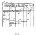
- FIG. 20 is a sequence chart (2) for explaining an NGN connection service procedure according to the second embodiment.
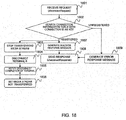
- FIG. 18 is a flowchart for explaining the operation in receiving a connection end request in the SOAP-SIP adapter 6 according to the second embodiment.
- FIG. 23 is a flowchart for explaining the operation in receiving a disconnect notice in the SOAP-SIP adapter 6 according to the second embodiment.
- steps S91 to S96 in FIG. 20 correspond to the processings of steps S82 to S87 as described above.
- the terminal A7a sends an SOAP disconnect Request (disconnect request) to the SOAP-SIP adapter 6a (S97).
- the SOAP disconnect Request includes the connection ID of the call to end the connection. More specifically, the terminal A7a generates the SOAP disconnect Request including the connection ID stored at step S64 as described above. As one example, the terminal A7a may select the connection ID of the call to end the connection from the connection ID stored at step S64 as described above, based on the user operation from the appropriate input part.
- the SOAP-SIP adapter 6a searches the connection information table 5010 held in the SOAP-SIP adapter 6a with the connection ID as the key, specifies the terminal 7 to be disconnected from the table information of the matched connection ID 5011, and disconnects it (S98 to S105). The detailed operation of steps S98 to S105 in the SOAP-SIP adapter 6a will be described below.
- the SOAP control part 5101a of the SOAP-SIP adapter 6a receives the SOAP disconnect Request, and sends a disconnect request (B) to the NGN connection module part 5102a (S98).
- This disconnect request (B) includes the connection ID in the SOAP disconnect Request.
- the NGN connection module part 5102a receives the disconnect request (1801), and searches the connection information table 5010 for the connection ID 5011, based on the connection ID included in the received disconnect request (B) (1802). If the connection ID included in the received disconnect request (B) is already registered in the connection information table 5010, the NGN connection module part 5102a generates a disconnect success response (1807), and sends the generated disconnect success response to the SOAP control part 5101a (S99).
- the SOAP control part 5101a receives the disconnect success response, and sends an SOAP disconnect Response to the terminal A7a (S100, 1808). For the SOAP disconnect Response, only the success response may be sent.
- the media stream control part 5103a stops the transfer of media stream (1803).
- the NGN connection module part 5102a may send a media stream transfer stop request to the media stream control part 5103a.
- the NGN connection module part 5102a generates the disconnect request (B) and sends it to the SIP control part 5104a (S101, 1804). More specifically, the NGN connection module part 5102a acquires the To URI 5027 by referring to the terminal information table 5020 corresponding to the pertinent connection ID 5011. The NGN connection module part 5102a sends the disconnect request (B) including the acquired To URI 5027 to the SIP control part 5104a.
- the SIP control part 5104a receives the disconnect request (B), and sends a BYE message (B) of the SIP to the SOAP-SIP adapter 6b in accordance with the To URI included in the received disconnect request (B) (S102).
- the SIP control part 5104b of the SOAP-SIP adapter 6b receives the BYE message (B) (2001), and sends a disconnect notice (A) to the NGN connection module part 5102b (S103). Also, the SIP control part 5104b sends a 200 OK (B) of the SIP to the SOAP-SIP adapter 6a (S104, 2002).
- the media stream control part 5103b stops the transfer of media stream (2003), and sets the media stream not transferred (2004).
- the NGN connection module part 5102b may send a media stream transfer stop request to the media stream control part 5103b.
- the SIP control part 5104a of the SOAP-SIP adapter 6a receives the 200 OK (B), and sends a disconnect complete notice (B) to the NGN connection module part 5102a (S105, 1805).
- the NGN connection module part 5102a receives the disconnect complete notice (B), and sets the media stream not transferred (1806).
- the NGN connection module part 5102a If the session ID included in the received call end request is not registered at step 1802, the NGN connection module part 5102a generates a call end request failure response (error response message) (1809), and sends the generated call end request failure response to the SOAP control part 5101a.
- the SOAP control part 5101a receives the call end request failure response, and sends the SOAP disconnect Response indicating the call end request failure to the terminal A7a (1808).
- a communication system has, for example, a first server (SOAP-SIP adapter 2), a device (terminal B5c, Client B) for making an establishment of connection with said first server in a SIP protocol, and a first terminal (terminal A5b, Client A) for communicating with said first server, said first server comprises:
- said device is a second terminal (terminal B5c, Client B)
- said communication system further comprises a second server (Web server 1) for sending said connection request message for communicating between said first terminal and said second terminal to said first server
- said processing part makes the establishment of connection for said first terminal and said second terminal in said SIP protocol
- said first transfer processing part transfers the data received from said second terminal to said first terminal and the data received from said first terminal to said second terminal.
- a communication system has a first server (SOAP-SIP adapter 6a), a device (SOAP-SIP adapter 6b) for making an establishment of connection with said first server in a SIP protocol, and a first terminal (terminal A7a, Client A) for communicating with said first server, said first server comprises:
- the communication system described above further comprises a second terminal (terminal B7b, Client B), said device is a third server (SOAP-SIP adapter server 6b) having a second transfer processing part (media stream control part 5103b), and said second transfer processing part receives said data transferred from said first transfer control part and transfers said data to said second terminal
- the present invention is applicable to the network such as an NGN, for example.
Landscapes
- Engineering & Computer Science (AREA)
- Computer Networks & Wireless Communication (AREA)
- Signal Processing (AREA)
- Multimedia (AREA)
- Business, Economics & Management (AREA)
- General Business, Economics & Management (AREA)
- Telephonic Communication Services (AREA)
- Computer And Data Communications (AREA)
- Data Exchanges In Wide-Area Networks (AREA)
Abstract
A SOAP-SIP adapter (2) establishes a session with the terminals (5b and 5c) in accordance with a SIP. At this time, the SOAP-SIP adapter (2) sends an INVITE message including its own IP address and port number to the terminals (5b and 5c). Each terminal (5b, 5c) sends a 200 OK including its own IP address and port number to the SOAP-SIP adapter (2). The SOAP-SIP adapter (2) stores correspondingly the IP address and port number of each terminal (5b, 5c) in a memory. The SOAP-SIP adapter (2) transfers a media stream received from each terminal (5b, 5c) to the destination of the corresponding IP address and port number by referring to the memory. Also, a pseudo RBT is sent to the terminal (A5b) from establishing the session with the terminal (A5b) till establishing the session with the terminal (B5c) to prevent a silent state.
Description
- The present application claims priority from Japanese patent application
JP 2009-057473 filed on March 11, 2009 - The present invention relates to a communication system and a server, and more particularly to a communication system and a server with an action points connection method in the next generation network.
- In recent years, various examinations for the communication network of the next generation with the common carrier using an Internet Protocol (IP) technique have been vigorously made. The next generation communication network of this kind is called an Next Generation Network (NGN). In the NGN, a method for establishing a session between the server and the client to be communicated and managing the band for each session is often employed. Also, in the NGN, a session control protocol for use in reserving the band is a Session Initiation Protocol (SIP), for example.
- Also, there has been disclosed another technique in which when a client apparatus mounting no control protocol for the session for reserving the band communicates in a band assured network, a session substituting device establishes the session for reserving the band in the band assured network, instead of the client apparatus (e.g., refer to
JP-A-2008-78878 - Also, a Simple Object Access Protocol (SOAP) for exchanging the information between applications has been known.
- In the NGN, it is required that the IP addresses for establishing the signaling channel and the data channel are the same. Therefore, there is a problem that it is impossible to substitute the establishment of the data channel between two parties (first connection terminal and second connection terminal) to be communicated such as the conventional 3rd Party Call Control (3PCC) service flow. Also, there is another problem in the 3PCC service flow that when the telephone communication is made between the first connection terminal and the second connection terminal by firstly establishing the session between an apparatus with the 3PCC and the first connection terminal and then establishing the session between the apparatus with the 3PCC and the second connection terminal, the first connection terminal is placed in a silent state at the stage where the establishment of the session with the first connection terminal is completed and the establishment of the session with the second connection terminal is started. Also, most of the existent application terminals have no SIP for reserving the communication band in the NGN, in which there is another problem that the communication on the NGN is impossible.
- In view of the above-mentioned problems, it is an object of the present invention to provide a communication system and a server for transferring the data between two parties (first connection terminal and second connection terminal) to be communicated in the NGN with assured communication quality. Also, it is another object of the invention to provide a 3PCC service on the NGN with assured communication quality. It is still another object of the invention to prevent the first connection terminal from being placed in the silent state in establishing the session with the second connection terminal after establishing the session with the first connection terminal in the 3PCC service flow.
- Further, it is another object of the invention to provide a communication system and a server in which the terminal can reserve the communication band on the NGN with the partner terminal without being aware of the SIP and communicate on the NGN with reserved band through the steady operation on the already existent internet after reserving the communication band. Also, it is another object of the invention to mount an interface capable of establishing many sessions on an SOAP-SIP adapter to make it possible to establish hundreds to thousands of sessions.
- According to the first solving means of present invention, there is provided a communication system having a first server, a device for making an establishment of connection with said first server in a SIP protocol, and a first terminal for communicating with said first server, wherein said first server comprises:
- an interface for receiving a connection request message;
- a processing part for making the establishment of connection with said device in said SIP protocol in accordance with received connection request message; and
- a first transfer control part for transferring data received from said first terminal to said device after the establishment of connection by said processing part.
- According to the second solving means of present invention, there is provided a server in a communication system which has said server, a device for making an establishment of connection with said server in a SIP protocol, and a terminal for communicating with said server, said server comprising:
- an interface for receiving a connection request message;
- a processing part for making the establishment of connection with said device in said SIP protocol in accordance with received connection request message; and
- a first transfer control part for transferring data received from said first terminal to said device after the establishment of connection by said processing part.
- According to the present invention, it is possible to provide a communication system and a server for transferring the data between two parties (first connection terminal and second connection terminal) to be communicated in the NGN with assured communication quality. According to the invention, it is possible to provide a 3PCC service on the NGN with assured communication quality. According to the invention, it ispossible to prevent the first connection terminal from being placed in the silent state in establishing the session with the second connection terminal after establishing the session with the first connection terminal in the 3PCC service flow.
- Further, according to the invention, it is possible to provide a communication system and a server in which the terminal can reserve the communication band on the NGN with the partner terminal without being aware of the SIP and communicate on the NGN with reserved band through the steady operation on the already existent internet after reserving the communication band. According to the invention, it is possible to mount an interface capable of establishing many sessions on an SOAP-SIP adapter to make it possible to establish hundreds to thousands of sessions.
-
-
FIG. 1 is an explanatory view showing a configuration example of a communication network according to a first embodiment. -
FIG. 2 is an explanatory view showing a configuration example of an SOAP-SIP adapter 2 according to the first embodiment. -
FIG. 3A is an explanatory view showing one example of the organization of a session information table 2010 in the SOAP-SIP adapter 2 according to the first embodiment. -
FIG. 3B is an explanatory view showing one example of the organization of a call participant information table 2020 in the SOAP-SIP adapter 2 according to the first embodiment. -
FIG. 3C is an explanatory view showing one example of the organization of a terminal information table 2030 in the SOAP-SIP adapter 2 according to the first embodiment. -
FIG. 3D is an explanatory view showing one example of the organization of a media stream control information table 2040 in the SOAP-SIP adapter 2 according to the first embodiment. -
FIG. 4 is an explanatory view showing a configuration example of a communication network according to a second embodiment. -
FIG. 5 is an explanatory view showing a configuration example of an SOAP-SIP adapter 6 according to the second embodiment. -
FIG. 6A is an explanatory view showing one example of the organization of a connection information table 5010 in the SOAP-SIP adapter 6a according to the second embodiment. -
FIG. 6B is an explanatory view showing one example of the organization of a terminal information table 5020 in the SOAP-SIP adapter 6a according to the second embodiment. -
FIG. 6C is an explanatory view showing one example of the organization of a media stream control information table 5030 in the SOAP-SIP adapter 6a according to the second embodiment. -
FIG. 7 is a flowchart for explaining the generation of a session ID/connection ID in the SOAP-SIP adapter. -
FIG. 8 is a flowchart for explaining the operation in receiving a call start request in the SOAP-SIP adapter 2 according to the first embodiment. -
FIG. 9 is a flowchart for explaining the operation in receiving a call information (session information) request in the SOAP-SIP adapter 2 according to the first embodiment. -
FIG. 10 is a flowchart for explaining the operation in receiving a call participant information request in the SOAP-SIP adapter 2 according to the first embodiment. -
FIG. 11 is a flowchart for explaining the operation in receiving a call end request in the SOAP-SIP adapter 2 according to the first embodiment. -
FIG. 12 is a sequence chart (1) for explaining a 3PCC service procedure according to the first embodiment. -
FIG. 13 is a sequence chart (2) for explaining the 3PCC service procedure according to the first embodiment. -
FIG. 14 is a sequence chart (3) for explaining the 3PCC service procedure according to the first embodiment. -
FIG. 15 is a sequence chart (4) for explaining the 3PCC service procedure according to the first embodiment. -
FIG. 16 is a flowchart for explaining the operation in receiving a connection start request in the SOAP-SIP adapter 6 according to the second embodiment. -
FIG. 17 is a flowchart for explaining the operation in receiving a connection information request in the SOAP-SIP adapter 6 according to the second embodiment. -
FIG. 18 is a flowchart for explaining the operation in receiving a connection end request in the SOAP-SIP adapter 6 according to the second embodiment. -
FIG. 19 is a sequence chart (1) for explaining an NGN connection service procedure according to the second embodiment. -
FIG. 20 is a sequence chart (2) for explaining the NGN connection service procedure according to the second embodiment. -
FIG. 21A is an explanatory view showing one example of the organization of a connection information table 6010 in the SOAP-SIP adapter 6a according to the second embodiment. -
FIG. 21B is an explanatory view showing one example of the organization of a terminal information table 6020 in the SOAP-SIP adapter 6b according to the second embodiment. -
FIG. 21C is an explanatory view showing one example of the organization of a media stream control information table 6030 in the SOAP-SIP adapter 6b according to the second embodiment. -
FIG. 22 is a flowchart for explaining the operation in receiving a call incoming notice in the SOAP-SIP adapter 6 according to the second embodiment. -
FIG. 23 is a flowchart for explaining the operation in receiving a disconnect notice in the SOAP-SIP adapter 6 according to the second embodiment. -
FIG. 24 is a configuration diagram of aweb server 1. -
FIG. 1 is an explanatory view showing a configuration example of a communication network according to a first embodiment. - This communication network (system) comprises a
Web server 1, an SOAP-SIP adapter 2, aSIP server 3, and an Home Gateway (HGW) 4a, 4b, for example. TheSIP server 3 is installed in an NGN N2, for example. - The
Web server 1 communicates with the SOAP-SIP adapter 2. Also, theWeb server 1 communicates via a network such as internet N1 with a terminal 5a. The SOAP-SIP adapter 2 communicates via the NGN N2 and theHGW 4a with a terminal A5b. The SOAP-SIP adapter 2 and a terminal B5c have also the same configuration. -
FIG. 2 is an explanatory view showing a configuration example of the SOAP-SIP adapter 2 according to the first embodiment. - The SOAP-
SIP adapter 2 comprises a processor (hereinafter CPU) 2001, an interface (hereinafter IF) 2003a, 2003b, and amemory 2004, for example. Thememory 2004 has anSOAP control part 2101, a3PCC module part 2102, a mediastream control part 2103, and aSIP control part 2104. The3PCC module part 2102 has a session information table 2010, and the mediastream control part 2103 has a media stream control information table 2040. The session information table 2010 has a call participant information table 2020 and a terminal information table 2030. - The
CPU 2001 performs each processing in the SOAP-SIP adapter 2. TheSOAP control part 2101, the3PCC module part 2102, the mediastream control part 2103 and theSIP control part 2104 on thememory 2004 are performed by theCPU 2001. TheIF 2003 is interface for making the communication via aline 2002 with theWeb server 1 and the NGN N2. -
FIG. 3A is an explanatory view showing one example of the organization of the session information table 2010 in the SOAP-SIP adapter 2 according to the first embodiment. - The session information table 2010 stores, associated with a
session ID 2011, asession state 2012, acall participant state 2020, and theterminal information 2030, for example. - The
session ID 2011 is a session identifier corresponding to a connection request from theWeb server 1. Thesession ID 2011 identifies the communication between the terminal A5b and the terminal B5c. Thesession state 2012 indicates the state of session designated by thesession ID 2011. Thesession state 2012 stores an "Initial (initial state)", a "Connected (connected state)", or a "Terminated (terminated state)", for example. Thecall participant state 2020 corresponds to the call participant information table 2020. The details of the call participant information table 2020 will be described below. Theterminal information 2030 corresponds to the terminal information table 2030. Theterminal information 2030 is stored for each terminal. In an illustrated example, the terminal information (for Client A) 2030_A corresponding to the terminal A5b and the terminal information (for Client B) 2030_B corresponding to the terminal B5c are stored. The details of the terminal information table 2030 will be described below. -
FIG. 3B is an explanatory view showing one example of the organization of the call participant information table 2020 in the SOAP-SIP adapter 2 according to the first embodiment. - The call participant information table 2020 stores, for each terminal, a
URI 2021, acall state 2022 and a start time (clock) 2023, for example. - The
URI 2021 indicates a SIP-URI corresponding to each user. Thecall state 2022 indicates the state of session of the SIP between the SOAP-SIP adapter 2 and each terminal 5b, 5c. Thecall state 2022 stores a "Call Participant Initial (Initial state)", a "Call Participant Connected (connected state)" or a "Call Participant Terminated (terminated state)", for example. Thestart time 2023 indicates the time when the SOAP-SIP adapter 2 establishes the session of the SIP for each terminal 5b, 5c. -
FIG. 3C is an explanatory view showing one example of the organization of the terminal information table 2030 in the SOAP-SIP adapter 2 according to the first embodiment. - The terminal information table 2030 stores the parameters for use in the SIP, for example. The terminal information table 2030 stores a
handle value 2031, asession ID 2032, aterminal state 2033, aRole 2034, the send Session Description Protocol (SDP)information 2035, therecv SDP information 2036, a FromURI 2037, and aTo URI 2038, for example. - The
handle value 2031 is the information for identifying the session of the SIP between the SOAP-SIP adapter 2 and the terminal 5b and the session of the SIP between the SOAP-SIP adapter 2 and the terminal B5c. Thesession ID 2032 corresponds to thesession ID 2011 of the session information table 2010. Theterminal state 2033 indicates the state till establishing the session between the SOAP-SIP adapter 2 and each terminal 5b, 5c. Theterminal state 2033 accepts an "Initial (initial state)", a "Connect Wait (state waiting for a 'response')", a "Call Complete (state accepting the 'response' and establishing the session with the UA, a "Close Wait (state waiting for a 'disconnect complete notice')", and a "Closed (terminated state)", for example. The "Initial" and the "Connect Wait" correspond to the "Call Participant Initial" of thecall state 2022 stored in the call participant information table 2020. Also, the "Call Complete" and the "Close Wait" correspond to the "Call Participant Connected" of thecall state 2022 stored in the call participant information table 2020. The "Close Wait" corresponds to the "Call Participant Terminated" of thecall state 2022. - The
Role 2034 is the information indicating the call outgoing side or call incoming side. The sendSDP information 2035 includes the IP address and the port number of the SOAP-SIP adapter 2, for example. Therecv SDP information 2036 includes the IP address and the port number of the terminal A5b or terminal B5c, for example. The FromURI 2037 indicates the sender URI of a SIP message sent by the SOAP-SIP adapter 2. The FromURI 2037 is the SIP-URI of the SOAP-SIP adapter 2, for example. TheTo URI 2038 indicates the destination URI of SIP message sent by the SOAP-SIP adapter 2. TheTo URI 2038 is the SIP-URI of the terminal A5b or terminal B5c, for example. -
FIG. 3D is an explanatory view showing one example of the organization of the media stream control information table 2040 in the SOAP-SIP adapter 2 according to the first embodiment. - The media stream control information table 2040 stores, associated with a
session ID 2041, a media stream sending/receivingIP address 2042, a media stream sending/receivingport number 2043, a partner IP address (1) 2044, a partner port number (1) 2045, a partner IP address (2) 2046, and a partner port number (2) 2047, for example. - The
session ID 2041 corresponds to thesession ID 2011 of the session information table 2010. The media stream sending/receivingIP address 2042 and the media stream sending/receivingport number 2043 are the IP address and the port number of theIF 2003 for use when the SOAP-SIP adapter 2 transfers the media stream. The pairs of the partner IP address (1) 2044 and the partner port number (1) 2045 and the partner IP address (2) 2046 and the partner port number (2) 2047 designate the destination of transferring the media stream. For example, in the case where the sender of the media stream corresponds to the partner IP address (1) 2044 and the partner port number (1) 2045, the media stream is transferred to the corresponding destination with the partner IP address (2) 2046 and the partner port number (2) 2047. In the case where the sender of the media stream corresponds to the partner IP address (2) 2046 and the partner port number (2) 2047, the media stream is transferred to the corresponding destination with the partner IP address (2) 2044 and partner port number (1) 2045 in the same manner. In an illustrated example, the partner IP address (1) 2044 and the partner port number (1) 2045 designate the IP address and the port number of the terminal A5b, and the partner IP address (2) 2046 and the partner port number (2) 2047 designate the IP address and the port number of the terminal B5c. -
FIG. 24 is a configuration diagram of theweb server 1. - The
web server 1 comprises aprocessing part 100, aninput part 110, adisplay part 120, astorage part 130, and acommunication interface 140, for example. Theinput part 110 receives the input of a Session ID or the input of a user identifier, for example. Thedisplay part 120 displays the user identifier and the SIP-URI. Thestorage part 130 stores the received Session ID, for example. Thecommunication interface 140 is the interface for communicating with the SOAP-SIP adapter 2, for example. Theprocessing part 100 performs various kinds of processing in theweb server 1. -
FIG. 12 is a sequence chart for explaining a 3PCC service procedure according to the first embodiment. -
FIG. 7 is a flowchart for explaining the generation of a session ID/connection ID in the SOAP-SIP adapter. The connection ID is used in the second embodiment.FIG. 8 is a flowchart for explaining the operation in receiving a call start request in the SOAP-SIP adapter 2 according to the first embodiment. - According to this embodiment, it is possible to provide the 3PCC service on the NGN with the assured communication quality.
- The flow up to the 3PCC service is the following (a) to (c). (a) Establishment of the session between the SOAP-
SIP adapter 2 and the first connection terminal A5b. (b) Establishment of the session between the SOAP-SIP adapter 2 and the second connection terminal B5c. (c) Telephone communication between the first connection terminal A5b and the second connection terminal B5c. However, there is a problem that the first connection terminal A5b is placed in a silent state at the stage where (a) is completed and (b) is started. Thus, a Ringing Back Tone, (RBT, connection maintaining message) is artificially sent from the SOAP-SIP adapter 2 to the first connection terminal A5b to resolve this problem. - Also, in the NGN, there is a necessary condition that the IP addresses for establishing the signaling channel and the data channel are the same, resulting in a problem that it is impossible to vicariously execute the establishment of data channel between two parties (the first connection terminal A5b and the second connection terminal B5c) to be communicated as in the conventional 3PCC service flow. Thus, in this embodiment, the data from the first connection terminal A5b is received by the SOAP-
SIP adapter 2 and transferred to the second connection terminal B5c. The data from the second connection terminal B5c is received by the SOAP-SIP adapter 2 and transferred to the first connection terminal A5b. Also, the SOAP-SIP adapter 2 creates the media stream control information table 2040 for implementing the above transfer. - The procedure of this embodiment will be described below in accordance with the sequence charts and the flowcharts.
- First of all, the user of the third party logs into the
Web server 1 by operating the terminal 5a. TheWeb server 1 inputs the user identifiers of the users to communicate (e.g., user names of two parties corresponding to the terminal A5b and the terminal B5c) from the terminal 5a. For example, theWeb server 1 may select the users of two parties to communicate through the operation of the user in accordance with the screen displayed for the terminal 5a that logs in. - The
Web server 1 sends an SOAP make Call Session Request (connection request) to the SOAP-SIP adapter 2 (S1). The SOAP make Call Session Request includes the SIP-URI corresponding to each of the user of two parties to be connected. For example, theWeb server 1 acquires the SIP-URI corresponding to the input user identifier, because the user identifier and the SIP-URI of the user are associated and prestored. The Web sever 1 generates the SOAP make Call Session Request including the acquired SIP-URI, and sends it to the SOAP-SIP adapter 2. - The SOAP-
SIP adapter 2 starts the connection to each terminal 5b, 5c corresponding to the SIP-URI included in the received SOAP make Call Session Request, and sends an SOAP make Call Session Response including the session ID generated in the SOAP-SIP adapter 2 (S2 to S15). The detailed operation of the steps S2 to S15 in the SOAP-SIP adapter 2 will be described below. - The
SOAP control part 2101 of the SOAP-SIP adapter 2 receives the SOAP make Call Session Request, and sends a connection request to the 3PCC module part 2102 (S2). This connection request can be generated in accordance with an appropriate protocol for use in the SOAP-SIP adapter 2, based on the received SOAP make Call Session Request, for example, and includes the SIP-URI within the SOAP make Call Session Request. - The
3PCC module part 2102 receives the connection request (7001, 8001), and generates a session ID (8002). Referring toFIG. 7 , the generation of the session ID will be described below. - The
3PCC module part 2102 receives the connection request and generates the random number value (7002). The3PCC module part 2102 judges whether or not the generated random number value is already registered in thesession ID 2011 of the session information table 2010 (7003). If the generated random number value is already registered (i.e., already used), the3PCC module part 2102 returns to step 7002 to repeat the subsequent processing. On the other hand, if the generated random number value is not registered, the3PCC module part 2102 stores the generated session ID in the session information table 2010 (7004). Further, the3PCC module part 2102 sets thesession state 2012 of the session information table 2010 to "Initial (initial state)". - Also, the
3PCC module part 2102 stores the SIP-URI included in the received connection request in the call participant information table 2020. In an example of the call participant information table 2020 as shown inFIG. 3B , the SIP-URI (see 2020_A) of the terminal A5b and the SIP-URI (see 2020_B) of the terminal B5c are stored. The3PCC module part 2102 sets thecall state 2022 corresponding to each terminal 5b, 5c of the call participant information table 2020 to "Call Participant Initial (initial state)". - Moreover, the
3PCC module part 2102 stores the terminal information of the terminal A5b and the terminal B5c. More specifically, the3PCC module part 2102 stores the generated session ID in the terminal information table 2030, associated with each terminal 5b, 5c. Also, the3PCC module part 2102 stores each SIP-URI included in the received connection request in theTo URI 2038 corresponding to each terminal 5b, 5c of the terminal information table 2030. The3PCC module part 2102 sets theterminal state 2032 corresponding to each terminal 5b, 5c of the terminal information table 2030 to "Initial (initial state)". The3PCC module part 2102 sets the information indicating the call outgoing side or call incoming side to theRole 2033 corresponding to each terminal 5b, 5c of the terminal information table 2030. It can be appropriately decided which of theterminals 3PCC module part 2102 stores the IP address and the port number of the SOAP-SIP adapter 2 in the sendSDP information 2035 of the terminal information table 2030. Also, the3PCC module part 2102 stores the SIP-URI of the SOAP-SIP adapter 2 in theFrom URI 2037 corresponding to each terminal 5b, 5c of the terminal information table 2030. The SIP-URI, the IP address and the port number of the SOAP-SIP adapter 2 are prestored in the appropriate storage part. - The
3PCC module part 2102 generates a connection request success response, and sends it to the SOAP control part 2101 (S3, 8011). The connection request success response includes the generated session ID. TheSOAP control part 2101 receives the connection request success response, and sends an SOAP make Call Session Response (connection request success response) to the Web server 1 (S4, 8012). The SOAP make Call Session Response includes the generated session ID, and is generated in accordance with the SOAP, based on the received connection request success response. TheWeb server 1 receives the SOAP make Call Session Response, and stores the session ID included in the received SOAP make Call Session Response in the appropriate storage part. - If the generation of the session ID fails at
step 8002, the3PCC module part 2102 generates a connection request failure response (error response message) (8013), and sends it to theSOAP control part 2101. TheSOAP control part 2101 receives the connection request failure response, and sends an SOAP make Call Session Response indicating the connection request failure to the Web server 1 (8012). - Next, the session between the SOAP-
SIP adapter 2 and the terminal A5b is established. - More specifically, the
3PCC module part 2102 acquires a media stream control/transfer port (8003). The3PCC module part 2102 sends a call outgoing request (A) for the terminal A5b to the SIP control part 2104 (S5, 8004). For example, the3PCC module part 2102 sends the call outgoing request including thesend SDP information 2035, the FromURI 2037 and theTo URI 2038 corresponding to the terminal A5b stored in the terminal information table 2030 to theSIP control part 2104. Also, the3PCC module part 2102 stores the current time as one example in thestart time 2023 corresponding to the terminal A5b of the call participant information table 2020. In an example of the call participant information table 2020 as shown inFIG. 3B , "2008.10.22 10:30.30" is stored. Thestart time 2023 is not limited to the current time, but may be the appropriate time indicating the start of session with the terminal A5b. - The
SIP control part 2104 sends an INVITE message (A) to the terminal A5b in accordance with the To URI included in the call outgoing request (A) (S6). The INVITE message (A) includes at least the send SDP information, the From URI, and the To URI included in the received call outgoing request, for example. Also, theSIP control part 2104 generates a handle value identifying the session with the terminal A5b. - The terminal A5b receives the INVITE message (A), and stores the IP address and the port number of the SOAP-
SIP adapter 2 included in the send SDP information of the received INVITE message (A) in the appropriate storage part. The stored IP address and port number are used in sending the media stream, for example. Also, the terminal A5b generates the recv SDP information including its own IP address and port number and sends a 200 OK (A) of the SIP including the generated SDP information to the SOAP-SIP adapter 2 (S7). TheSIP control part 2104 of the SOAP-SIP adapter 2 receives the 200 OK (A) and sends an ACK (A) of the SIP to the terminal A5b (S8). - The
SIP control part 2104 sends a response notice (A) to the 3PCC module part 2102 (S9, 8005). The response notice (A) includes the handle value generated at step S6 and the recv SDP information of the terminal A5b included in the 200 OK received at step S7, for example. The3PCC module part 2102 stores, associated with the terminal A5b, the handle value and the recv SDP information included in the received response notice (A) in the terminal information table 2030. The handle value may be stored at an appropriate timing from step S6 to step S8. The3PCC module part 2102 updates theterminal state 2033 corresponding to the terminal A5b of the terminal information table 2030 to "Call Complete (session established state)". Also, the3PCC module part 2102 updates thecall state 2022 corresponding to the terminal A5b of the call participant information table 2020 to "Call Participant Connected (connected state)". Theterminal state 2033 may be appropriately updated upon sending or receiving the SIP message (e.g., 200 OK and so on), for example. - Also, the
3PCC module part 2102 sends the generated session ID, the IP address and port number of the SOAP-SIP adapter 2, and the IP address and port number of the terminal A5b included in the received recv SDP information to the mediastream control part 2103. The mediastream control part 2103 stores the received information in the media stream control information table 2040. For example, the mediastream control part 2103 stores the received IP address and port number of the SOAP-SIP adapter 2 at the media stream sending/receivingIP address 2042 and the media stream sending/receivingport number 2043, and stores the received IP address and port number of the terminal A5b at the partner IP address (1) 2044 and the partner port number (1) 2045. Also, the mediastream control part 2103 stores the received session ID. - The
3PCC module part 2102 sends a pseudo RBT sending request to the media stream control part 2103 (S101). The mediastream control part 2103 receives the pseudo RBT sending request, and sends the pseudo RBT to the terminal A5b in accordance with a Real-time Transport Protocol (RTP), for example (S10, 8006). The mediastream control part 2103 may use an announcement of calling the partner or appropriate music, for example, as the pseudo RBT. In this embodiment, the terminal A5b is prevented from being in silent state at the stage where the establishment of session with the terminal A5b is completed and the establishment of session with the terminal B5c is started. This pseudo RBT can continue to be sent until a stop request is made as will be described later. - Next, the session between the SOAP-
SIP adapter 2 and the terminal B5c is established. - The
3PCC module part 2102 sends a call outgoing request (B) for the terminal B5c to the SIP control part 2104 (S11, 8007). For example, the3PCC module part 2102 sends the call outgoing request including thesend SDP information 2035, the FromURI 2037 and theTo URI 2038 corresponding to the terminal B5c stored in the terminal information table 2030 to theSIP control part 2104. Also, the3PCC module part 2102 stores the current time in thestart time 2023 corresponding to the terminal B5c of the call participant information table 2020. In an example of the call participant information table 2020 as shown inFIG. 3B , "2008.10.22 10:30.45" is stored. - The
SIP control part 2104 sends an INVITE message (B) to the terminal B5c in accordance with the To URI included in the call outgoing request (A) (S12). The INVITE message (B) includes at least the send SDP information, the From URI, and the To URI included in the received call outgoing request, for example. Also, theSIP control part 2104 generates a handle value identifying the session with the terminal B5c. - The terminal B5c receives the INVITE message (B), and stores the IP address and port number of the SOAP-
SIP adapter 2 included in the send SDP information of the received INVITE message (B) in the appropriate storage part. Also, the terminal B5c generates the recv SDP information including its own IP address and port number and sends a 200 OK (B) including the generated recv SDP information to the SOAP-SIP adapter 2 (S13). TheSIP control part 2104 of the SOAP-SIP adapter 2 receives the 200 OK (B) and sends an ACK (B) to the terminal B5c (S14). - The
SIP control part 2104 sends a response notice (B) to the 3PCC module part 2102 (S15, 8008). The response notice (B) includes the handle value generated at step S12 and the recv SDP information of the terminal B5c included in the 200 OK received at step S13, for example. The3PCC module part 2102 stores the handle value and the recv SDP information included in the received response notice (B) in the terminal information table 2030, associated with the terminal B5c. The handle value may be stored at an appropriate timing from step S12 to step S14. The3PCC module part 2102 updates theterminal state 2033 corresponding to the terminal B5c of the terminal information table 2030 to "Call Complete (session established state)". Also, the3PCC module part 2102 updates thecall state 2022 corresponding to the terminal B5c of the call participant information table 2020 to "Call Participant Connected (connected state)". Also, the3PCC module part 2102 updates the session state of the session information table 2010 to "Connected (connected state)". - The
3PCC module part 2102 sends the session ID, and the IP address and port number of the terminal B5c included in the received recv SDP information to the mediastream control part 2103. The mediastream control part 2103 stores, associated with the received session ID, the IP address and port number of the terminal B5c in the partner IP address (2) 2046 and the partner port number (2) 2047 of the media stream control information table 2040. - The
3PCC module part 2102 sends a pseudo RBT stop request to the media stream control part 2103 (S102, 8009). The mediastream control part 2103 stops sending the pseudo RBT in accordance with the pseudo RBT stop request. - The SOAP-
SIP adapter 2 starts to transfer the media stream between the terminal A5b and the terminal B5c (8010). - For example, the terminal A5b sends the media stream to the SOAP-
SIP adapter 2 in accordance with the RTP (S16). At this time, the terminal A5b sets the IP address and port number of the SOAP-SIP adapter 2 stored at step S6 to the destination, and sets its own IP address and port number to the sender. - The media
stream control part 2103 of the SOAP-SIP adapter 2 transfers the received media stream to the terminal B5c by referring to the media stream control information table 2040 (S17). For example, the mediastream control part 2103 acquires the corresponding partner IP address and port number by referring to the media stream control information table 2040 based on the sender IP address and port number of the received media stream. In an example of the media stream control information table 2040 as shown inFIG. 3D , the sender IP address and port number of the received media stream are the IP address (10.0.2.1) and port number (20000) of the terminal A5b, and the corresponding partner IP address (2) 2046 (10.0.2.2) and port number (2) 2047 (30000) are acquired. The mediastream control part 2103 transfers the received media stream to the terminal B5c in accordance with the acquired IP address and port number. - Similarly, the terminal B5c sends the media stream to the SOAP-
SIP adapter 2 in accordance with the RTP (S18). In the same manner as the case of the terminal A5b, the terminal B5c sets the IP address and port number of the SOAP-SIP adapter 2 stored at step S12 to the destination, and sets its own IP address and port number to the sender. - The media
stream control part 2103 of the SOAP-SIP adapter 2 transfers the received media stream to the terminal A5b by referring to the media stream control information table 2040 (S19). In an example of the media stream control information table 2040 as shown inFIG. 3D , the sender IP address and port number of the received media stream are the IP address (10.0.2.2) and port number (30000) of the terminal B5c, and the corresponding partner IP address (1) 2044 (10.0.2.1) and port number (1) 2045 (20000) are acquired. The mediastream control part 2103 transfers the received data stream to the terminal A5b in accordance with the acquired IP address and port number. - As described above, the IP address establishing the signaling channel and the IP address establishing the data channel become the same, whereby the data from the terminal A5b is received by the SOAP-
SIP adapter 2 and transferred to the terminal B5c, and the data from the terminal B5c is received by the SOAP-SIP adapter 2 and transferred to the terminal A5b, so that the 3PCC service on the NGN with the assured communication quality is enabled. -
FIG. 13 is a sequence chart (2) for explaining the 3PCC service procedure according to the first embodiment.FIG. 9 is a flowchart for explaining the operation in receiving a call information (session information) request in the SOAP-SIP adapter 2 according to the first embodiment. - Referring to
FIGs. 13 and9 , the operation that theWeb server 1 acquires the call information will be described below. Herein, theWeb server 1 can acquire the information corresponding to the designated session ID. The processings of steps S21 to S24 inFIG. 13 correspond to the processings of steps S16 to S19 as described above. - The
Web server 1 sends an SOAP get Call Session Information Request (session information request, call information request) to the SOAP-SIP adapter 2 (S25). The SOAP get Call Session Information Request includes the session ID of the call information to be acquired. More specifically, the Web sever 1 generates the SOAP get Call Session Information Request including the session ID stored at step S4 as described above, and sends it to the SOAP-SIP adapter 2. TheWeb server 1 may select the session ID of the call information to be acquired from the session ID stored at step S4 as described above, based on the user operation from the terminal 5a. - The SOAP-
SIP adapter 2 searches the session information table 2010 held in the SOAP-SIP adapter 2 with the session ID included in the SOAP get Call Session Information Request as the key, and sends the SOAP get Call Session Information Response including the table information of the matched session ID 2011 (S26 to S28). The detailed operation of steps S26 to S28 in the SOAP-SIP adapter 2 will be described below. - First of all, the
SOAP control part 2101 of the SOAP-SIP adapter 2 receives the SOAP get Call Session Information Request, and sends a session information request to the 3PCC module part 2102 (S26). This session information request includes the session ID in the SOAP get Call Session Information Request. - The
3PCC module part 2102 receives the session information request (9001), and searches the session information table 2010 for thesession ID 2011 based on the session ID included in the received session information request (9002). If the session ID included in the received session information request is already registered in the session information table 2010, the session information corresponding to thepertinent session ID 2011 is specified (9003). The3PCC module part 2102 acquires theURI 2021 and thecall state 2022 corresponding to each terminal 5b, 5c, for example, by referring to the call participant information table (call participant state) 2020 corresponding to the pertinent session ID 2011 (9004). Further, the3PCC module part 2102 acquires therecv SDP information 2036 of each terminal from the terminal information (for Client A) 2030_A and the terminal information (for Client B) 2030_B corresponding to thepertinent session ID 2011, for example. - The
3PCC module part 2102 generates a session information request success response including thesession ID 2011, the acquiredURI 2021, thecall state 2022 and the recv SDP information 2036 (9005), and sends the generated session information request success response to the SOAP control part 2101 (S27). TheSOAP control part 2101 receives the session information request success response, and sends an SOAP get Call Session Information Response (session information request success response) to the Web server 1 (S28, 9006). The SOAP get Call Session Information Response includes the session ID, the URI, the call state and the recv SDP information in the received session information request success response and is generates in accordance with the SOAP. - If the session ID included in the received session information request is not registered at
step 9002, the3PCC module part 2102 generates a session information request failure response (error response message) (9007), and sends the generated session information request failure response to theSOAP control part 2101. TheSOAP control part 2101 receives the session information request failure response, and sends the SOAP get Call Session Information Response indicating the session information request failure to the Web server 1 (9006). - The
Web server 1 receives the SOAP get Call Session Information Response, and can confirm the session state as to whether or not the requested communication comes into existence by referring to the call state included in the received SOAP get Call Session Information Response, for example. For example, if the call is terminated from the terminal, the call state becomes "Call Participant Terminated (terminated state)", whereby theWeb server 1 can judge that the call is terminated from the terminal A5b or terminal B5c. Also, for example, if the call state is not normal, theWeb server 1 may stop the communication using an SOAP end Call Session Request as will be described later. -
FIG. 14 is a sequence chart (3) for explaining the 3PCC service procedure according to the first embodiment.FIG. 10 is a flowchart for explaining the operation in receiving a call participant information request in the SOAP-SIP adapter 2 according to the first embodiment. - Referring to
FIGs. 14 and10 , the operation that theWeb server 1 acquires the call participant information will be described below. Herein, theWeb server 1 can acquire the user information corresponding to the designated SIP-URI. The processings of steps S31 to S34 inFIG. 14 correspond to the processings of steps S16 to S19 as described above. - The
Web server 1 sends an SOAP get Call Participants Information Request (call participant information request) to the SOAP-SIP adapter 2 (S35). The SOAP get Call Participants Information Request includes the session ID and URI of the call participant information to be acquired. More specifically, the Web sever 1 generates the SOAP get Call Session Information Request including the session ID stored at step S4 as described above and the SIP-URI of the desired call participant, and sends it to the SOAP-SIP adapter 2. As one example, theWeb server 1 may select the session ID and the user identifier (e.g., user name corresponding to the terminal A5b, terminal B5c) of the call information to be acquired based on the user operation from the terminal 5a. TheWeb server 1 can acquire the SIP-URI corresponding to the input user identifier, because the user identifier and the SIP-URI of the user are associated and prestored as above described. - The SOAP-
SIP adapter 2 searches the session information table 2010 held in the SOAP-SIP adapter 2 with the session ID included in the SOAP get Call Participants Information Request as the key, and specifies the table information of the matchedsession ID 2011. Further, the SOAP-SIP adapter 2 searches the call participant information table 2020 with the SIP-URI included in the SOAP get Call Participants Information Request as the key, and sends the SOAP get Call Participants Information Response including the table information corresponding to the matched SIP-URI 2021 (S36 to S38). The operation of steps S36 to S38 in the SOAP-SIP adapter 2 will be described below. - The
SOAP control part 2101 of the SOAP-SIP adapter 2 receives the SOAP get Call Participants Information Request, and sends a call participant information request to the 3PCC module part 2102 (S36). This call participant information request includes the session ID and the SIP-URI in the SOAP get Call Participants Information Request. The3PCC module part 2102 receives the call participant information request (1001), and searches the session information table 2010 for thesession ID 2011, based on the session ID included in the received call participant information request (1002). If the session ID included in the received call participant information request is already registered in the session information table 2010, the session information is specified by the pertinent session ID 2011 (1003). The3PCC module part 2102 searches the call participant information table (call participant state) 2020 corresponding to thepertinent session ID 2011 for theURI 2021, based on the SIP-URI included in the received call participant information request (1004). If the SIP-URI included in the received call participant information request is already registered, the3PCC module part 2102 acquires thecall state 2022 corresponding to the pertinent URI 2021 (1005). Also, the3PCC module part 2102 acquires the corresponding recvSDP information 2036 by referring to theTo URI 2038 of the terminal information table 2030, based on the SIP-URI included in the received call participant information request. - The
3PCC module part 2102 generates a call participant information request success response including theURI 2021, the acquiredcall state 2022 and the recv SDP information 2036 (1006), and sends the generated call participant information request success response to the SOAP control part 2101 (S37). TheSOAP control part 2101 receives the call participant information request success response, and sends an SOAP get Call Participants Information Response (call participant information request success response) to the Web server 1 (S38, 1007). The SOAP get Call Participants Information Response includes the URI, the call state and the recv SDP information in the received call participant information request success response and is generated in accordance with the SOAP. - If the session ID included in the received call participant information request is not registered at
step 1002, and the SIP-URI included in the received call participant information request is not registered atstep 1004, the3PCC module part 2102 generates a call participant information request failure response (error response message) (1008), and sends the generated call participant information request failure response to theSOAP control part 2101. TheSOAP control part 2101 receives the call participant information request failure response, and sends the SOAP get Call Participants Information Response indicating the call participant information request failure to the Web server 1 (1007). -
FIG. 15 is a sequence chart (4) for explaining the 3PCC service procedure according to the first embodiment.FIG. 11 is a flowchart for explaining the operation in receiving a call end request in the SOAP-SIP adapter 2 according to the first embodiment. - Referring to
FIGs. 15 and11 , the operation that theWeb server 1 ends the call will be described below. The processings of steps S41 to S44 inFIG. 15 correspond to the processings of steps S16 to S19 as described above. - The
Web server 1 sends an SOAP end Call Session Request (call end request) to the SOAP-SIP adapter 2 (S45). The SOAP end Call Session Request includes the session ID of the call to be ended. More specifically, the Web sever 1 generates the SOAP end Call Session Request including the session ID stored at step S4 as described above, and sends it to the SOAP-SIP adapter 2. As one example, theWeb server 1 may select the session ID of the call to be ended from the session ID stored at step S4 as described above, based on the user operation from the terminal 5a. - The SOAP-
SIP adapter 2 searches the session information table 2010 held in the SOAP-SIP adapter 2 with the session ID included in the SOAP end Call Session Request as the key, specifies theterminals session ID 2011 and disconnects them (S46 to S56). The detailed operation of steps S46 to S56 in the SOAP-SIP adapter 2 will be described below. - The
SOAP control part 2101 of the SOAP-SIP adapter 2 receives the SOAP end Call Session Request (call end request), and sends the call end request to the 3PCC module part 2102 (S46). This call end request includes the session ID in the SOAP end Call Session Request. The3PCC module part 2102 receives the call end request (1101), and searches the session information table 2010 for thesession ID 2011, based on the session ID included in the received call end request (1102). - If the session ID included in the received call end request is already registered in the session information table 2010, the
3PCC module part 2102 generates a call end request success response (1109), and sends the generated call end request success response to the SOAP control part 2101 (S47). TheSOAP control part 2101 receives the call end request success response, and sends an SOAP end Call Session Response (call end request success response) to the Web server 1 (S48, 1110). For the Soap end Call Session Response, only the success response may be sent. - Also, the session information is specified by the
pertinent session ID 2011 to specify the two parties (here the terminal A5b, terminal B5c) during the telephone communication (1103). For example, the3PCC module part 2102 acquires the SIP-URI 2021 of each terminal A5b, terminal B5c by referring to the call participant information table 2020 corresponding to the session ID included in the received call end request. The mediastream control part 2103 stops the transfer of media stream (1104). A media stream transfer stop request may be sent from the3PCC module part 2102 to the mediastream control part 2103. - The
3PCC module part 2102 sends a disconnect request (A) including the acquired SIP-URI to theSIP control part 2104 in accordance with one of the acquired SIP-URIs (S49, 1105). TheSIP control part 2104 receives the disconnect request (A), and sends a BYE message (A) of the SIP to the terminal A5b with the SIP-URI included in the received disconnect request (A) as the To URI (S50). - Likewise, the
3PCC module part 2102 sends a disconnect request (B) including the acquired SIP-URI to theSIP control part 2104 in accordance with the other acquired SIP-URI (S51, 1106). TheSIP control part 2104 receives the disconnect request (B), and sends a BYE message (B) to the terminal B5c with the SIP-URI included in the received disconnect request (B) as the To URI (S52). - The terminal A5b sends a 200 OK (A) for the BYE message (A) received at step S50 to the SOAP-SIP adapter 2 (S53). The
SIP control part 2104 of the SOAP-SIP adapter 2 receives the 200 OK (A), and sends a disconnect complete notice (A) to the 3PCC module part 2102 (S54, 1107). - Likewise, the terminal B5c sends a 200 OK (B) for the BYE message (B) received at step S52 to the SOAP-SIP adapter 2 (S55). The
SIP control part 2104 of the SOAP-SIP adapter 2 receives the 200 OK (B), and sends a disconnect complete notice (B) to the 3PCC module part 2102 (S56, 1108). - If the session ID included in the received call end request is not registered at
step 1102, the3PCC module part 2102 generates a call end request failure response (error response message) (1111), and sends the generated call end request failure response to theSOAP control part 2101. TheSOAP control part 2101 receives the call end request failure response, and sends the SOAP end Call Session Response indicating the call end request failure to the Web server 1 (1110). -
FIG. 4 is an explanatory view showing a configuration example of a communication network according to a second embodiment. - The communication network (system) of this embodiment comprises a
SIP server 3 and an SOAP-SIP adapter SIP server 3 is installed in an NGN N2. - The SOAP-
SIP adapter 6a communicates via the NGN N2 with the SOAP-SIP adapter 6b. Also, a terminal 7a and a terminal 7b communicate via the SOAP-SIP adapter 6a and the SOAP-SIP adapter 6b. It is predetermined which SOAP-SIP adapter 6 theterminal 7 is connected to, in which the SOAP-SIP adapter 6a and the terminal A7a correspond one to one, and the SOAP-SIP adapter 6b and the terminal B7b also correspond one to one. For example, to communicate with the terminal B7b, it is possible to communicate with the terminal B7b if the SOAP-SIP adapter 6b is designated. Also, the SOAP-SIP adapter 6 and theterminal 7 may correspond one to many, and the correspondence between the SOAP-SIP adapter 6 and theterminal 7 to be connected may be stored in an appropriate device. -
FIG. 5 is an explanatory view showing a configuration example of the SOAP-SIP adapter 6 according to the second embodiment. - The SOAP-SIP adapter 6 of this embodiment comprises an NGN
connection module part 5102, instead of the3PCC module part 2102 of the first embodiment, for example. The NGNconnection module part 5102 has a connection information table 5010, which has a terminal information table 5020. ACPU 5001, an IF 5003a, 5003b, anSOAP control part 5101, a mediastream control part 5103, and aSIP control part 5104 are the same as those of the first embodiment. -
FIG. 6A is an explanatory view showing one example of the organization of the connection information table 5010 in the SOAP-SIP adapter 6a according to the second embodiment. - The connection information table 5010 stores, associated with a
connection ID 5011, aconnection state 5012 and theterminal information 5013, for example. - The
connection ID 5011 is the information identifying the connection corresponding to the connection request from theterminal 7. For example, the connection in the Transmission Control Protocol (TCP) is identified. Theconnection ID 5011 is generated for each SOAP-SIP adapter 6. Theconnection state 5012 indicates the state of connection, corresponds to thesession state 2012 of the first embodiment, for example, and stores the same state. Theterminal information 5013 corresponds to the terminal information table 5020. -
FIG. 6B is an explanatory view showing one example of the organization of the terminal information table 5020 in the SOAP-SIP adapter 6a according to the second embodiment. - The terminal information table 5020 stores a
handle value 5021, aconnection ID 5022, aterminal state 5023, the sendSDP information 5024, therecv SDP information 5025, a FromURI 5026 and aTo URI 5027, for example. - The
handle value 5021 is the information identifying the session of SIP between the SOAP-SIP adapter 6a and the SOAP-SIP adapter 6b. Theconnection ID 5022 corresponds to theconnection ID 5011 in the connection information table 5010 as described above. Theterminal state 5023 indicates the state of session between the SOAP-SIP adapter 6a and the SOAP-SIP adapter 6b. Theterminal state 5023 is stored in the same state as theterminal state 2033 of the first embodiment, for example. The sendSDP information 5024 includes the IP address and the port number of the SOAP-SIP adapter 6 itself, for example. In an example of the SOAP-SIP adapter 6a as shown inFIG. 6B , it includes the IP address (10.0.1.1) and the port number (10000) of the SOAP-SIP adapter 6a. Therecv SDP information 5025 includes the IP address and the port number of the SOAP-SIP adapter 6 to be connected, for example. In the example ofFIG. 6B , it includes the IP address (10.0.2.1) and the port number (20000) of the SOAP-SIP adapter 6b. The FromURI 5026 indicates the SIP-URI of the SOAP-SIP adapter 6 itself, for example. In the example ofFIG. 6B , it indicates the SIP-URI of the SOAP-SIP adapter 6a. TheTo URI 5027 indicates the SIP-URI of the SOAP-SIP adapter 6 to be connected, for example. In the example ofFIG. 6B , it indicates the SIP-URI of the SOAP-SIP adapter 6b. -
FIG. 6C is an explanatory view showing one example of the organization of the media stream control information table 5030 in the SOAP-SIP adapter 6a according to the second embodiment. - The media stream control information table 5030 of this embodiment stores a
connection ID 5031, instead of thesession ID 2041 of the first embodiment, for example. - The
connection ID 5031 corresponds to theconnection ID 5011 of the connection information table 5010. The other items, including a media stream sending/receivingIP address 5032, a media stream sending/receivingport number 5033, a partner IP address (1) 5034, a partner port number (1) 5035, a partner IP address (2) 5036, and a partner port number (2) 5037 are the same as those of the first embodiment. In the SOAP-SIP adapter 6a of this embodiment, the partner IP address (1) 5034 and the partner port number (1) 5035 store the IP address and the port number of the SOAP-SIP adapter 6b, and the partner IP address (2) 5036 and the partner port number (2) 5037 store the IP address and the port number of the terminal A7a. Also, the media stream sending/receivingIP address 5032 and the media stream sending/receivingport number 5033 store the IP address and the port number of the SOAP-SIP adapter 6a as in the first embodiment. -
FIG. 21A is an explanatory view showing one example of the organization of a connection information table 6010 in the SOAP-SIP adapter 6b according to the second embodiment.FIG. 21B is an explanatory view showing one example of the organization of a terminal information table 6020 in the SOAP-SIP adapter 6b according to the second embodiment.FIG. 21C is an explanatory view showing one example of the organization of a media stream control information table 6030 in the SOAP-SIP adapter 6b according to the second embodiment. - The organization of each table 6010, 6020, 6030 in the SOAP-
SIP adapter 6b is the same as that of each table 5010, 5020, 5030 in the SOAP-SIP adapter 6a as described above. - In the terminal information table 6020 of the SOAP-
SIP adapter 6b, the IP address and the port number of the SOAP-SIP adapter 6b are stored in the sendSDP information 6024, and the IP address and the port number of the SOAP-SIP adapter 6a to be connected is stored in therecv SDP information 6025. Also, a FromURI 6026 indicates the SIP-URI of the SOAP-SIP adapter 6b and aTo URI 6027 indicates the SIP-URI of the SOAP-SIP adapter 6a. - Also, in the media stream control information table 6030, a partner IP address (1) 6034 and a partner port number (1) 6035 store the IP address and the port number of the SOAP-
SIP adapter 6a, and a partner IP address (2) 6036 and a partner port number (2) 6037 store the IP address and the port number of the terminal B7b. A media stream sending/receivingIP address 6032 and a media stream sending/receivingport number 6033 store the IP address and the port number of the SOAP-SIP adapter 6b. -
FIG. 19 is a sequence chart (1) for explaining an NGN connection service procedure according to the second embodiment.FIG. 16 is a flowchart for explaining the operation in receiving a connection start request in the SOAP-SIP adapter 6 according to the second embodiment.FIG. 22 is a flowchart for explaining the operation in receiving a call incoming notice in the SOAP-SIP adapter 6 according to the second embodiment.FIG. 17 is a flowchart for explaining the operation in receiving a connection information request in the SOAP-SIP adapter 6 according to the second embodiment. - In this embodiment, it is possible to provide a service for connecting the self terminal and the other partner terminal on the NGN with the assured communication quality without being aware of the protocol of the SIP.
- Most of the existent application terminals mount no SIP for reserving the communication band on the NGN, and have a problem that the communication on the NGN is impossible. In this embodiment, it is possible to reserve the communication band with the partner terminal B7b without being aware of the SIP by sending a connection start request SOAP message to the SOAP-SIP adapter 6 with a trigger of selecting the partner to be communicated on the screen of the terminal A7a, as one example. After reserving the communication band, the
terminal 7 can make the communication on the reserved band through the already existent operation that is indifferent from the internet. - The operation that the terminal 7 starts the connection will be described below.
- The terminal A7a connected to the SOAP-
SIP adapter 6a opens (breaks) a queue port for the SOAP-SIP adapter 6a at the start up, for example. Thereby, sending and receiving the data between the terminal A7a and the SOAP-SIP adapter 6a is enabled. At this time, the SOAP-SIP adapter 6a receives the IP address and port number of the terminal A7a, and stores the received IP address and port number of the terminal A7a in the appropriate storage part. The terminal B7b and the SOAP-SIP adapter 6b have also the same configuration. Theterminal 7 is not limited to the above example, but may open the queue port at an appropriate timing. The terminal A7a sends an SOAP connect Request (connection request) to the SOAP-SIP adapter 6a (S61). The SOAP connect Request includes the SIP-URI of the SOAP-SIP adapter 6b corresponding to the terminal B7b to be connected. For example, the terminal A7a may select the user identifier of the user or the SIP-URI of the SOAP-SIP adapter 6 to be connected from the appropriate input part, based on the user operation. In selecting the user identifier, for example, the terminal A7a may specify the SIP-URI of the SOAP-SIP adapter 6 corresponding to the input user identifier, because the user identifier and the SIP-URI of the SOAP-SIP adapter 6 to which theterminal 7 of the user is connected are associated and prestored. Also, a Web server in which the user identifier and the SIP-URI of the SOAP-SIP adapter 6 to which theuser terminal 7 is connected are associated and prestored may be installed, and the Web server may return the SIP-URI of the SOAP-SIP adapter 6 corresponding to the user identifier selected at the terminal A7a. - The
SOAP control part 5101a of the SOAP-SIP adapter 6a receives the SOAP connect Request, and sends a connection request (B) to the NGNconnection module part 5102a of the SOAP-SIP adapter 6a (S62). This connection request (B) includes the SIP-URI in the SOAP connect Request. The SOAP-SIP adapter 6a starts the connection to this SIP-URI. - More specifically, first of all, the NGN
connection module part 5102a receives the connection request (B) (1601), and generates the connection ID (1602). The generation of the connection ID is the same as inFIG. 7 and its description of the first embodiment. Referring toFIGs. 6A and6B , this embodiment will be described below, although the explanation is partially duplicated with that ofFIG. 7 . The NGNconnection module part 5102a stores the generated connection ID in the connection information table 5010 and the terminal information table 5020. The NGNconnection module part 5102a sets theconnection state 5012 of the connection information table 5010 to "Initial (initial state)". Further, the NGNconnection module part 5102a stores the SIP-URI included in the received connection request (B) in theTo URI 5027 of the terminal information table 5020. - Also, the NGN
connection module part 5102a sets theterminal state 5023 of the terminal information table 5020 to "Initial (initial state)". The NGNconnection module part 5102a stores the sendSDP information 5024 including the IP address and the port number of the SOAP-SIP adapter 6a in the terminal information table 5020. Also, the NGNconnection module part 5102a stores the SIP-URI of the SOAP-SIP adapter 6a in theFrom URI 5026 of the terminal information table 5020. The SIP-URI, the IP address and the port number of the SOAP-SIP adapter 6a are prestored in the appropriate storage part. - The NGN
connection module part 5102a generates a connection success response (B) (1607), and sends the generated connection success response (B) to theSOAP control part 5101a (S63). The connection success response (B) includes the generated connection ID. TheSOAP control part 5101a receives the connection success response (B), and sends an SOAP connect Response (connection success response) to the terminal A7a (S64, 1608). The SOAP connect Response includes the connection ID in the received connection success response (B), and is generated in accordance with the SOAP. The terminal A7a receives the SOAP connect Response, and stores the connection ID included in the received SOAP connect Response in the appropriate storage part. - If the generation of the connection ID fails at
step 1602, the NGNconnection module part 5102a generates a connection request failure response (error response message) (1609), and sends it to theSOAP control part 5101a. TheSOAP control part 5101a receives the connection request failure response, and sends the SOAP connect Response indicating the connection request failure to the terminal A7a (1608). - Next, the SOAP-
SIP adapter 6a establishes the session with the SOAP-SIP adapter 6b. - First of all, the NGN
connection module part 5102a acquires a media stream control transfer port (1603). The NGNconnection module part 5102a sends a call outgoing request (B) to theSIP control part 5104a of the SOAP-SIP adapter 6a (S65, 1604). The call outgoing request (B) includes the sendSDP information 5024, the FromURI 5026 and theTo URI 5027 stored in the terminal information table 5020. - The
SIP control part 5104a receives the call outgoing request (B), and sends an INVITE message (B) of the SIP to the SOAP-SIP adapter 6b in accordance with the To URI included in the received call outgoing request (B) (S66). The INVITE message (B) includes at least the send SDP information, the From URI, and the To URI in the received call outgoing request (B), for example. Also, theSIP control part 5104a generates the handle value identifying the session of the SIP with the SOAP-SIP adapter 6b. - The operation of each part in the SOAP-
SIP adapter 6b will be described below. - The
SIP control part 5104b of the SOAP-SIP adapter 6b receives the INVITE message (B), and sends a call incoming notice (A) to the NGNconnection module part 5102b of the SOAP-SIP adapter 6b (S67). The call incoming notice (A) includes the send SDP information, the From URI and the To URI in the received INVITE message (B). - The NGN
connection module part 5102b receives the call incoming notice (A) (1901), and generates the connection ID (1902). In this embodiment, the connection ID is generated independently in the SOAP-SIP adapter 6a and the SOAP-SIP adapter 6b. The generation of the connection ID is the same as atstep 1602 as described above. The NGNconnection module part 5102b stores the generated connection ID in the connection information table 6010 and the terminal information table 6020. The NGNconnection module part 5102b sets the connection state 6012 of the connection information table 6010. For example, it sets the connection state 6012 to "Initial (initial state)" or "Connected (connected state)". The "Initial" or "Connected" may be changed at an appropriate timing. Moreover, the NGNconnection module part 5102b stores the send SDP information included in the received call incoming notice (A) in therecv SDP information 6025 of the terminal information table 6020. The NGNconnection module part 5102b stores the From URI included in the received call incoming notice (A) in theTo URI 6027 of the terminal information table 6020, and similarly stores the To URI (i.e., its own SIP-URI) included in the received call incoming notice (A) in theFrom URI 6026. - Also, the NGN
connection module part 5102b sets theterminal state 6023 of the terminal information table 6020. For example, it appropriately sets theterminal state 6023 to "Initial (initial state)" or "Call Complete (session established state)". Theterminal state 6023 may be appropriately changed. The NGNconnection module part 5102b stores the IP address and the port number of the SOAP-SIP adapter 6b in the sendSDP information 6024 of the terminal information table 6020. The IP address and the port number of the SOAP-SIP adapter 6b are prestored in the appropriate storage part. Also, theSIP control part 5104b generates the handle value identifying the session of the SIP with the SOAP-SIP adapter 6a and stores it in the terminal information table 6020. - The NGN
connection module part 5102b of the SOAP-SIP adapter 6b acquires the media stream control transfer port (1903). The NGNconnection module part 5102b sends the generated connection ID, the IP address and port number of the SOAP-SIP adapter 6a included in the send SDP information in the received call incoming notice (A), and the IP address and port number of the terminal B7b stored by port open to the mediastream control part 5103b. The mediastream control part 5103b stores each received information in the media stream control information table 6030. For example, the mediastream control part 5103b stores the received IP address and port number of the SOAP-SIP adapter 6a in the partner IP address (1) 6034 and the partner port number (1) 6035, and stores the received IP address and port number of the terminal B7b in the partner IP address (2) 6036 and the partner port number (2) 6037. Also, the mediastream control part 5103b stores the received connection ID, and stores its own IP address and port number in the media stream sending/receivingIP address 6032 and the media stream sending/receivingport number 6033. Thereby, the SOAP-SIP adapter 6b can start the transfer of media stream (1904). - The NGN
connection module part 5102b generates a response (A), and sends it to theSIP control part 5104b (S68, 1905). The response (A) includes the sendSDP information 6024, the FromURI 6026 and theTo URI 6027 stored in the terminal information table 6020. TheSIP control part 5104b receives the response (A), and sends a 200 OK (B) of the SIP to the SOAP-SIP adapter 6a (S69). The 200 OK (B) includes at least the send SDP information, the From URI and the To URI in the received response (A), for example. - If the generation of the connection ID fails at
step 1902 as described above, the NGNconnection module part 5102b disconnects the session of SIP with the SOAP-SIP adapter corresponding to the terminal A7a (1906). - Returning to the description of the SOAP-
SIP adapter 6a, theSIP control part 5104a of the SOAP-SIP adapter 6a receives the 200 OK (B) and sends an ACK (B) of the SIP to the SOAP-SIP adapter 6b (S70). TheSIP control part 5104a sends a response notice (B) to the NGNconnection module part 5102a (S71, 1605). The response notice (B) includes the handle value generated at step S66 and the send SDP information included in the 200 OK (B) received at step S69. The NGNconnection module part 5102a stores the handle value included in the received response notice (B) in the terminal information table 5020. Also, the NGNconnection module part 5102a stores the send SDP information included in the received response notice (B) in therecv SDP information 5025 of the terminal information table 5020. The handle value may be stored at an appropriate timing. The NGNconnection module part 5102a updates theterminal state 5023 of the terminal information table 5020 to "Call Complete (session established state)". Also, the NGNconnection module part 5102a updates theconnection state 5012 of the connection information table 5010 to "Connected (connected state)". Theterminal state 2023 may be updated appropriately in sending or receiving the SIP message (e.g., 200 OK and so on). - The NGN
connection module part 5102a sends the generated connection ID, the IP address and port number of the terminal A7a stored by port open, the IP address and port number of the SOAP-SIP adapter 6b included in the received send SDP information to the mediastream control part 5103a. The mediastream control part 5103a stores each received information in the media stream control information table 5030. For example, the mediastream control part 5103a stores the received IP address and port number of the SOAP-SIP adapter 6b in the partner IP address (1) 5034 and the partner port number (1) 5035, and stores the received IP address and port number of the terminal A7a in the partner IP address (2) 5036 and the partner port number (2) 5037. Also, the mediastream control part 5103a stores the received connection ID, and stores its own IP address and port number in the media stream sending/receivingIP address 5032 and the media stream sending/receivingport number 5033. Thereby, the SOAP-SIP adapter 6a can start the transfer of media stream (1606). - Next, the operation that the
terminal 7 acquires the connection information will be described below. - The terminal A7a sends an SOAP get Connection Information List Request (connection information request) to the SOAP-
SIP adapter 6a (S72). The SOAP get Connection Information List Request includes the connection ID of the connect information (connection information) to be acquired. More specifically, the terminal A7a generates the SOAP get Connection Information List Request including the connection ID stored at step S64 as described above. As one example, the terminal A7a periodically performs the processing at step S72 after receiving the SOAP connection Response at step S64. - The SOAP-
SIP adapter 6a searches the connection information table 5010 held in the SOAP-SIP adapter 6a with the connection ID included in the SOAP get Connection Information List Request as the key, and sends an SOAP get Connection Information List Response including the table information of the matched connection ID 5011 (S73 to S75). The detailed operation of steps S73 to S75 in the SOAP-SIP adapter 6a will be described below. - First of all, the
SOAP control part 5101a of the SOAP-SIP adapter 6a receives the SOAP get Connection Information List Request, and sends a connection information request to the NGNconnection module part 5102a (S73). This connection information request includes the connection ID in the SOAP get Connection Information List Request. - The NGN
connection module part 5102a receives the connection information request (1701), and searches the connection information table 5010 for theconnection ID 5011, based on the connection ID included in the received connection information request (1702). If the connection ID included in the received connection information request is already registered in the connection information table 5010, the connection information corresponding to thepertinent connection ID 5011 is specified (1703). The NGNconnection module part 5102a acquires theconnection state 5012 corresponding to the pertinent connection ID 5011 (1704). The NGNconnection module part 5102a is not limited to theconnection state 5012, but may further acquire appropriate information stored in the connection information table 5010 and the terminal information table 5020. - The NGN
connection module part 5102a generates a connection information success response including the acquired connection state 5012 (1705), and sends the generated connection information success response to theSOAP control part 5101a (S74). TheSOAP control part 5101a receives the connection information success response, and sends an SOAP get Connection Information List Response to the terminal A7a (S75, 1706). The SOAP get Connection Information List Response includes the connection state in the received connection information success response, and is generated in accordance with the SOAP. - If the connection ID included in the received connection information request is not registered in the connection information table 5010 at
step 1702, the NGNconnection module part 5102a generates a connection information failure response (error response message) (1707), and sends the generated connection information failure response to theSOAP control part 5101a. TheSOAP control part 5101a receives the connection information failure response, and sends the SOAP get Connection Information List Response indicating the connection information request failure to the terminal A7a (1706). - The terminal A7a receives the SOAP get Connection Information List Response, and can confirm the state of connection by referring to the connection state included in the received SOAP get Connection Information List Response. Thereby, if it is confirmed that the connection state is "Connected (connected state)", for example, terminal A7a and the terminal B7b start the signaling at the AP level in accordance with the HTTP (S76 to S81), and communicate the media stream in accordance with the RTP (S82 to S87).
- The transfer of signal and media stream will be described below in connection with the media stream from the terminal A7a to the terminal B7b, for example. The terminal A7a sends the media stream from the sender with its own IP address and port number set to the destination with the IP address and port number of the SOAP-
SIP adapter 6a set (S82). The IP address and the port number of the SOAP-SIP adapter 6a are prestored in the appropriate storage part. - The media
stream control part 5103a of the SOAP-SIP adapter 6a transfers the received media stream to the SOAP-SIP adapter 6b by referring to the media stream control information table 5030 (S83). The transfer operation is the same as in the first embodiment. Referring toFIG. 6C , the SOAP-SIP adapter 6a of this embodiment will be described below. The sender IP address and port number of the received media stream are the IP address (192.168.10.1) and port number (30000) of the terminal A7a, whereby the corresponding partner IP address (1) 5034 (10.0.2.1) and port number (1) 5035 (20000) are acquired. The NGNconnection module part 5102a transfers the received media stream to the SOAP-SIP adapter 6b in accordance with the acquired IP address and port number. Also, at this time, the NGNconnection module part 5102a sets the media stream sending/receivingIP address 5032 and the media stream sending/receivingport number 5033 of the media stream control information table 5030 to the sender. - The media
stream control part 5103b of the SOAP-SIP adapter 6b receives the media stream, and transfers a received signal to the terminal B7b by referring to the media stream control information table 6030 (S84). Referring toFIG. 21C , the SOAP-SIP adapter 6b of this embodiment will be described below. The sender IP address and port number of the received media stream are the IP address (10.0.1.1) and port number (10000) of the SOAP-SIP adapter 6a, whereby the corresponding partner IP address (2) 6036 (192.168.10.2) and port number (2) 6037 (40000) are acquired. The NGNconnection module part 5102b transfers the received media stream to the terminal B7b in accordance with the acquired IP address and port number. Also, at this time, the NGNconnection module part 5102b sets the media stream sending/receivingIP address 6032 and the media stream sending/receivingport number 6033 of the media stream control information table 6030 to the sender. - In the case of sending the media stream from the terminal B7b to the terminal A7a (S85 to S87), and the case of sending or receiving the signal at the AP level between the terminal A7a and the terminal B7b (S76 to S81), the operation is also made in the same manner.
- As described above, it is possible to reserve the communication band with the partner terminal B7b without being aware of the SIP by sending a connection start request SOAP message to the SOAP-
SIP adapter 6a with a trigger of selecting the partner to be communicated on the screen of the terminal A7a, as one example. After reserving the communication band, theterminal 7 can make the communication on the NGN N2 with the reserved band through the already existent operation that is indifferent from the internet. Also, the IP address establishing the signaling channel and the IP address establishing the data channel are the same. -
FIG. 20 is a sequence chart (2) for explaining an NGN connection service procedure according to the second embodiment.FIG. 18 is a flowchart for explaining the operation in receiving a connection end request in the SOAP-SIP adapter 6 according to the second embodiment.FIG. 23 is a flowchart for explaining the operation in receiving a disconnect notice in the SOAP-SIP adapter 6 according to the second embodiment. - Referring to
FIGS. 20 ,18 and23 , the operation of ending the connection will be described below. The processings of steps S91 to S96 inFIG. 20 correspond to the processings of steps S82 to S87 as described above. - The terminal A7a sends an SOAP disconnect Request (disconnect request) to the SOAP-
SIP adapter 6a (S97). The SOAP disconnect Request includes the connection ID of the call to end the connection. More specifically, the terminal A7a generates the SOAP disconnect Request including the connection ID stored at step S64 as described above. As one example, the terminal A7a may select the connection ID of the call to end the connection from the connection ID stored at step S64 as described above, based on the user operation from the appropriate input part. - The SOAP-
SIP adapter 6a searches the connection information table 5010 held in the SOAP-SIP adapter 6a with the connection ID as the key, specifies theterminal 7 to be disconnected from the table information of the matchedconnection ID 5011, and disconnects it (S98 to S105). The detailed operation of steps S98 to S105 in the SOAP-SIP adapter 6a will be described below. - First of all, the
SOAP control part 5101a of the SOAP-SIP adapter 6a receives the SOAP disconnect Request, and sends a disconnect request (B) to the NGNconnection module part 5102a (S98). This disconnect request (B) includes the connection ID in the SOAP disconnect Request. - The NGN
connection module part 5102a receives the disconnect request (1801), and searches the connection information table 5010 for theconnection ID 5011, based on the connection ID included in the received disconnect request (B) (1802). If the connection ID included in the received disconnect request (B) is already registered in the connection information table 5010, the NGNconnection module part 5102a generates a disconnect success response (1807), and sends the generated disconnect success response to theSOAP control part 5101a (S99). TheSOAP control part 5101a receives the disconnect success response, and sends an SOAP disconnect Response to the terminal A7a (S100, 1808). For the SOAP disconnect Response, only the success response may be sent. - Also, the media
stream control part 5103a stops the transfer of media stream (1803). The NGNconnection module part 5102a may send a media stream transfer stop request to the mediastream control part 5103a. - The NGN
connection module part 5102a generates the disconnect request (B) and sends it to theSIP control part 5104a (S101, 1804). More specifically, the NGNconnection module part 5102a acquires theTo URI 5027 by referring to the terminal information table 5020 corresponding to thepertinent connection ID 5011. The NGNconnection module part 5102a sends the disconnect request (B) including the acquired ToURI 5027 to theSIP control part 5104a. - The
SIP control part 5104a receives the disconnect request (B), and sends a BYE message (B) of the SIP to the SOAP-SIP adapter 6b in accordance with the To URI included in the received disconnect request (B) (S102). TheSIP control part 5104b of the SOAP-SIP adapter 6b receives the BYE message (B) (2001), and sends a disconnect notice (A) to the NGNconnection module part 5102b (S103). Also, theSIP control part 5104b sends a 200 OK (B) of the SIP to the SOAP-SIP adapter 6a (S104, 2002). - The media
stream control part 5103b stops the transfer of media stream (2003), and sets the media stream not transferred (2004). The NGNconnection module part 5102b may send a media stream transfer stop request to the mediastream control part 5103b. - The
SIP control part 5104a of the SOAP-SIP adapter 6a receives the 200 OK (B), and sends a disconnect complete notice (B) to the NGNconnection module part 5102a (S105, 1805). The NGNconnection module part 5102a receives the disconnect complete notice (B), and sets the media stream not transferred (1806). - If the session ID included in the received call end request is not registered at
step 1802, the NGNconnection module part 5102a generates a call end request failure response (error response message) (1809), and sends the generated call end request failure response to theSOAP control part 5101a. - The
SOAP control part 5101a receives the call end request failure response, and sends the SOAP disconnect Response indicating the call end request failure to the terminal A7a (1808). - According to the first embodiment, a communication system has, for example, a first server (SOAP-SIP adapter 2), a device (terminal B5c, Client B) for making an establishment of connection with said first server in a SIP protocol, and a first terminal (terminal A5b, Client A) for communicating with said first server, said first server comprises:
- an interface (SOAP control part) for receiving a connection request message (SOAP makeCallSessionRequest);
- a processing part (3PCC module part, SIP control part) for making the establishment of connection with said device in said SIP protocol in accordance with said received connection request message; and
- a first transfer control part (media stream control part) for transferring data received from said first terminal to said device after the establishment of connection by said processing part.
- In the communication system described above,
said device is a second terminal (terminal B5c, Client B),
said communication system further comprises a second server (Web server 1) for sending said connection request message for communicating between said first terminal and said second terminal to said first server,
said processing part makes the establishment of connection for said first terminal and said second terminal in said SIP protocol, and
said first transfer processing part transfers the data received from said second terminal to said first terminal and the data received from said first terminal to said second terminal. - According to the second embodiment, a communication system has a first server (SOAP-
SIP adapter 6a), a device (SOAP-SIP adapter 6b) for making an establishment of connection with said first server in a SIP protocol, and a first terminal (terminal A7a, Client A) for communicating with said first server, said first server comprises: - an interface (SOAP control part) for receiving a connection request message (SOAP connectRequest);
- a processing part (3PCC module part, SIP control part) for making the establishment of connection with said device in said SIP protocol in accordance with said received connection request message; and
- a first transfer control part (media stream control part) for transferring data received from said first terminal to said device after the establishment of connection by said processing part.
- The communication system described above further comprises a second terminal (terminal B7b, Client B),
said device is a third server (SOAP-SIP adapter server 6b) having a second transfer processing part (mediastream control part 5103b), and
said second transfer processing part receives said data transferred from said first transfer control part and transfers said data to said second terminal - The present invention is applicable to the network such as an NGN, for example.
- Features, components and specific details of the structures of the above-described embodiments may be exchanged or combined to form further embodiments optimized for the respective application. As far as those modifications are apparent for an expert skilled in the art they shall be disclosed implicitly by the above description without specifying explicitly every possible combination.
Claims (14)
- A communication system having a first server (2; 6a), a device (B5c; 6b) for making an establishment of connection with said first server (2; 6a) in a SIP protocol, and a first terminal (A5b) for communicating with said first server (2; 6a), wherein said first server (2; 6a) comprises:an interface (2101) for receiving a connection request message;a processing part (2102; 2104) for making the establishment of connection with said device (B5c; 6b) in said SIP protocol in accordance with received connection request message; anda first transfer control part (2103) for transferring data received from said first terminal (A5b) to said device (B5c; 6b) after the establishment of connection by said processing part (2102; 2104).
- The communication system according to claim 1, wherein
said device is a second terminal (B5c),
said communication system further comprises a second server (1) for sending said connection request message for communicating between said first terminal (A5b) and said second terminal (B5c) to said first server (2; 6a),
said processing part (2102; 2104) makes the establishment of connection for said first terminal (A5b) and said second terminal (B5c) in said SIP protocol, and
said first transfer processing part (2103) transfers the data received from said second terminal (B5c) to said first terminal (A5b) and the data received from said first terminal (A5b) to said second terminal (B5c). - The communication system according to claim 1 or 2, wherein
said communication system further comprises a second terminal (B7b),
said device is a third server (6b) having a second transfer processing part (5103), and
said second transfer processing part (5103) receives said data transferred from said first transfer control part (2103) and transfers said data to said second terminal (B7b). - The communication system according to claim 3, wherein said first terminal (A5b) sends the connection request message for communicating with said second terminal (B5c) to said first server (2; 6a).
- The communication system according to claim 2, wherein said processing part (2102; 2104) generates a session ID (2011, 2032, 2041) concerning the session between said first terminal (A5b) and said second terminal (B5c), based on said connection request message.
- The communication system according to claim 2, wherein said first server (2; 6a) further comprises a storage part (2010) for storing, associated with said session ID (2011, 2032, 2041), the first session information concerning the session with said first terminal (A5b) and the second session information concerning the session with said second terminal (B5c).
- The communication system according to claim 5 or 6, wherein
said second server (1) further comprises an input part for accepting the input of said session ID (2011, 2032, 2041), and
said processing part (2102; 2104) receives an information request including said session ID (2011, 2032, 2041) inputted by said input part via said interface (2101) from said second server(1), performs a search process for said storage part (2010) based on said session ID (2011, 2032, 2041), and sends the first and second session information corresponding to the pertinent session ID via said interface (2101) to said second server(1). - The communication system according to claim 6 or 7, wherein
said storage (2010) part stores said first session information associated with a SIP-URI of an user of said first terminal (A5b), and said second session information associated with the SIP-URI of the user of said second terminal (B5c),
said second server (1) further comprises an input part for accepting the input of said session ID (2011, 2032, 2041) and said SIP-URI, and
said processing part (2102; 2104) receives an information request including said session ID (2011, 2032, 2041) and said SIP-URI inputted by said input part via said second interface from said second server (1), performs a search process for said storage part (2010) based on said session ID (2011, 2032, 2041) and said SIP-URI, and sends the first session information or second session information corresponding to the pertinent session ID and SIP-URI via said interface to said second server (1). - The communication system according to claim 2, wherein said first server (2; 6a) sends a connection maintaining message to said first terminal (A5b) or said second terminal (B5c) after said processing part (2102; 2104) makes said establishment of connection for said first terminal (A5b) or said second terminal (B5c).
- The communication system according to claim 6, wherein said second server (1) further comprises an input part for accepting the input of said session ID (2011, 2032, 2041), and
said processing part (2102; 2104) receives a disconnect request including said session ID (2011, 2032, 2041) inputted by said input part via said interface (2101) from said second server (1), and sets the disconnection of said first terminal (A5b) and/or said second terminal (B5c) in said SIP protocol for the session corresponding to said session ID (2011, 2032, 2041). - The communication system according to at least one of claims 1 to 10, wherein said processing part (2102; 2104) comprises a 3PCC module (2102).
- The communication system according to claim 2, wherein said first transfer control part (2103)
acquires the address information items of said first terminal (A5b) and said second terminal (B5c) in said establishment of connection for said first terminal (A5b) and said second terminal (B5c),
stores a pair of address information items of said first terminal (A5b) and said second terminal (B5c), and
transfers the data received from said second terminal (B5c) to said first terminal (A5b) and the data received from said first terminal (A5b) to said second terminal (B5c) by referring to stored pair of address information items. - The communication system according to claim 2, wherein
said processing part (2102; 2104) notifies the address information of said first server (2; 6a) to said first terminal (A5b) and said second terminal (B5c) in the establishment of connection for said first terminal (A5b) and said second terminal (B5c), and
said first terminal (A5b) and said second terminal (B5c) sends the data to said first server (2; 6a) with the notified address information as the destination. - A server (2; 6a) in a communication system which has said server, a device (B5c; 6b) for making an establishment of connection with said server in a SIP protocol, and a terminal for communicating with said server, said server comprising:an interface (2101) for receiving a connection request message;a processing part (2102; 2104) for making the establishment of connection with said device (B5c) in said SIP protocol in accordance with received connection request message; anda first transfer control part (2103) for transferring data received from said first terminal (A5b) to said device (B5c; 6b) after the establishment of connection by said processing part (2102; 2104).
Applications Claiming Priority (1)
| Application Number | Priority Date | Filing Date | Title |
|---|---|---|---|
| JP2009057473A JP4920052B2 (en) | 2009-03-11 | 2009-03-11 | Communication system and server |
Publications (1)
| Publication Number | Publication Date |
|---|---|
| EP2228971A1 true EP2228971A1 (en) | 2010-09-15 |
Family
ID=42288587
Family Applications (1)
| Application Number | Title | Priority Date | Filing Date |
|---|---|---|---|
| EP10151177A Withdrawn EP2228971A1 (en) | 2009-03-11 | 2010-01-20 | Communication system and server |
Country Status (4)
| Country | Link |
|---|---|
| US (2) | US8706892B2 (en) |
| EP (1) | EP2228971A1 (en) |
| JP (1) | JP4920052B2 (en) |
| CN (1) | CN101834779B (en) |
Cited By (1)
| Publication number | Priority date | Publication date | Assignee | Title |
|---|---|---|---|---|
| US20140143314A1 (en) * | 2012-11-22 | 2014-05-22 | Hitachi, Ltd. | Communication system |
Families Citing this family (147)
| Publication number | Priority date | Publication date | Assignee | Title |
|---|---|---|---|---|
| US9456054B2 (en) | 2008-05-16 | 2016-09-27 | Palo Alto Research Center Incorporated | Controlling the spread of interests and content in a content centric network |
| US8923293B2 (en) | 2009-10-21 | 2014-12-30 | Palo Alto Research Center Incorporated | Adaptive multi-interface use for content networking |
| JP5325871B2 (en) | 2010-11-11 | 2013-10-23 | 株式会社日立製作所 | Communication system and server |
| US9178917B2 (en) * | 2010-12-16 | 2015-11-03 | Palo Alto Research Center Incorporated | Custodian routing with network address translation in content-centric networks |
| EP2735203B1 (en) | 2011-07-22 | 2019-05-08 | BlackBerry Limited | Method and apparatuses for using non-ims connections in ims sessions |
| US9280546B2 (en) | 2012-10-31 | 2016-03-08 | Palo Alto Research Center Incorporated | System and method for accessing digital content using a location-independent name |
| US20140136508A1 (en) | 2012-11-09 | 2014-05-15 | Palo Alto Research Center Incorporated | Computer-Implemented System And Method For Providing Website Navigation Recommendations |
| US9400800B2 (en) | 2012-11-19 | 2016-07-26 | Palo Alto Research Center Incorporated | Data transport by named content synchronization |
| US10430839B2 (en) | 2012-12-12 | 2019-10-01 | Cisco Technology, Inc. | Distributed advertisement insertion in content-centric networks |
| WO2014098860A1 (en) * | 2012-12-20 | 2014-06-26 | Unify Gmbh & Co. Kg | Method, device, and system for connecting to a communication device |
| US9978025B2 (en) | 2013-03-20 | 2018-05-22 | Cisco Technology, Inc. | Ordered-element naming for name-based packet forwarding |
| KR102029285B1 (en) * | 2013-04-01 | 2019-10-07 | 한국전자통신연구원 | System and method for big data aggregaton in sensor network |
| CN103179229B (en) * | 2013-04-17 | 2015-12-09 | 华为技术有限公司 | A kind of data service communications method, equipment and system |
| US9935791B2 (en) | 2013-05-20 | 2018-04-03 | Cisco Technology, Inc. | Method and system for name resolution across heterogeneous architectures |
| US9185120B2 (en) | 2013-05-23 | 2015-11-10 | Palo Alto Research Center Incorporated | Method and system for mitigating interest flooding attacks in content-centric networks |
| CN103338267B (en) * | 2013-07-18 | 2016-10-12 | 厦门大学 | The intelligent movable community value-added service platform that a kind of SIP and Web service are merged |
| JP5677526B2 (en) * | 2013-07-19 | 2015-02-25 | 株式会社日立製作所 | Control device and communication history management method |
| US9444722B2 (en) | 2013-08-01 | 2016-09-13 | Palo Alto Research Center Incorporated | Method and apparatus for configuring routing paths in a custodian-based routing architecture |
| US10250579B2 (en) * | 2013-08-13 | 2019-04-02 | Alcatel Lucent | Secure file transfers within network-based storage |
| US9407549B2 (en) | 2013-10-29 | 2016-08-02 | Palo Alto Research Center Incorporated | System and method for hash-based forwarding of packets with hierarchically structured variable-length identifiers |
| US9282050B2 (en) | 2013-10-30 | 2016-03-08 | Palo Alto Research Center Incorporated | System and method for minimum path MTU discovery in content centric networks |
| US9276840B2 (en) | 2013-10-30 | 2016-03-01 | Palo Alto Research Center Incorporated | Interest messages with a payload for a named data network |
| US9401864B2 (en) | 2013-10-31 | 2016-07-26 | Palo Alto Research Center Incorporated | Express header for packets with hierarchically structured variable-length identifiers |
| US10129365B2 (en) | 2013-11-13 | 2018-11-13 | Cisco Technology, Inc. | Method and apparatus for pre-fetching remote content based on static and dynamic recommendations |
| US10101801B2 (en) | 2013-11-13 | 2018-10-16 | Cisco Technology, Inc. | Method and apparatus for prefetching content in a data stream |
| US9311377B2 (en) | 2013-11-13 | 2016-04-12 | Palo Alto Research Center Incorporated | Method and apparatus for performing server handoff in a name-based content distribution system |
| US10089655B2 (en) | 2013-11-27 | 2018-10-02 | Cisco Technology, Inc. | Method and apparatus for scalable data broadcasting |
| US9503358B2 (en) | 2013-12-05 | 2016-11-22 | Palo Alto Research Center Incorporated | Distance-based routing in an information-centric network |
| US9379979B2 (en) | 2014-01-14 | 2016-06-28 | Palo Alto Research Center Incorporated | Method and apparatus for establishing a virtual interface for a set of mutual-listener devices |
| US10098051B2 (en) | 2014-01-22 | 2018-10-09 | Cisco Technology, Inc. | Gateways and routing in software-defined manets |
| US10172068B2 (en) | 2014-01-22 | 2019-01-01 | Cisco Technology, Inc. | Service-oriented routing in software-defined MANETs |
| US9374304B2 (en) | 2014-01-24 | 2016-06-21 | Palo Alto Research Center Incorporated | End-to end route tracing over a named-data network |
| US9531679B2 (en) | 2014-02-06 | 2016-12-27 | Palo Alto Research Center Incorporated | Content-based transport security for distributed producers |
| US9954678B2 (en) | 2014-02-06 | 2018-04-24 | Cisco Technology, Inc. | Content-based transport security |
| US9678998B2 (en) | 2014-02-28 | 2017-06-13 | Cisco Technology, Inc. | Content name resolution for information centric networking |
| US10089651B2 (en) | 2014-03-03 | 2018-10-02 | Cisco Technology, Inc. | Method and apparatus for streaming advertisements in a scalable data broadcasting system |
| US9836540B2 (en) | 2014-03-04 | 2017-12-05 | Cisco Technology, Inc. | System and method for direct storage access in a content-centric network |
| US9473405B2 (en) | 2014-03-10 | 2016-10-18 | Palo Alto Research Center Incorporated | Concurrent hashes and sub-hashes on data streams |
| US9626413B2 (en) | 2014-03-10 | 2017-04-18 | Cisco Systems, Inc. | System and method for ranking content popularity in a content-centric network |
| US9391896B2 (en) | 2014-03-10 | 2016-07-12 | Palo Alto Research Center Incorporated | System and method for packet forwarding using a conjunctive normal form strategy in a content-centric network |
| US9407432B2 (en) | 2014-03-19 | 2016-08-02 | Palo Alto Research Center Incorporated | System and method for efficient and secure distribution of digital content |
| US9916601B2 (en) | 2014-03-21 | 2018-03-13 | Cisco Technology, Inc. | Marketplace for presenting advertisements in a scalable data broadcasting system |
| US9363179B2 (en) | 2014-03-26 | 2016-06-07 | Palo Alto Research Center Incorporated | Multi-publisher routing protocol for named data networks |
| US9363086B2 (en) | 2014-03-31 | 2016-06-07 | Palo Alto Research Center Incorporated | Aggregate signing of data in content centric networking |
| US9716622B2 (en) | 2014-04-01 | 2017-07-25 | Cisco Technology, Inc. | System and method for dynamic name configuration in content-centric networks |
| US9473576B2 (en) | 2014-04-07 | 2016-10-18 | Palo Alto Research Center Incorporated | Service discovery using collection synchronization with exact names |
| US9390289B2 (en) | 2014-04-07 | 2016-07-12 | Palo Alto Research Center Incorporated | Secure collection synchronization using matched network names |
| US10075521B2 (en) | 2014-04-07 | 2018-09-11 | Cisco Technology, Inc. | Collection synchronization using equality matched network names |
| US9451032B2 (en) | 2014-04-10 | 2016-09-20 | Palo Alto Research Center Incorporated | System and method for simple service discovery in content-centric networks |
| US9203885B2 (en) | 2014-04-28 | 2015-12-01 | Palo Alto Research Center Incorporated | Method and apparatus for exchanging bidirectional streams over a content centric network |
| US9992281B2 (en) | 2014-05-01 | 2018-06-05 | Cisco Technology, Inc. | Accountable content stores for information centric networks |
| US9609014B2 (en) | 2014-05-22 | 2017-03-28 | Cisco Systems, Inc. | Method and apparatus for preventing insertion of malicious content at a named data network router |
| US9455835B2 (en) | 2014-05-23 | 2016-09-27 | Palo Alto Research Center Incorporated | System and method for circular link resolution with hash-based names in content-centric networks |
| US9276751B2 (en) | 2014-05-28 | 2016-03-01 | Palo Alto Research Center Incorporated | System and method for circular link resolution with computable hash-based names in content-centric networks |
| US9467377B2 (en) | 2014-06-19 | 2016-10-11 | Palo Alto Research Center Incorporated | Associating consumer states with interests in a content-centric network |
| US9537719B2 (en) | 2014-06-19 | 2017-01-03 | Palo Alto Research Center Incorporated | Method and apparatus for deploying a minimal-cost CCN topology |
| US9516144B2 (en) | 2014-06-19 | 2016-12-06 | Palo Alto Research Center Incorporated | Cut-through forwarding of CCNx message fragments with IP encapsulation |
| US9426113B2 (en) | 2014-06-30 | 2016-08-23 | Palo Alto Research Center Incorporated | System and method for managing devices over a content centric network |
| US9699198B2 (en) | 2014-07-07 | 2017-07-04 | Cisco Technology, Inc. | System and method for parallel secure content bootstrapping in content-centric networks |
| US9959156B2 (en) | 2014-07-17 | 2018-05-01 | Cisco Technology, Inc. | Interest return control message |
| US9621354B2 (en) | 2014-07-17 | 2017-04-11 | Cisco Systems, Inc. | Reconstructable content objects |
| US9590887B2 (en) | 2014-07-18 | 2017-03-07 | Cisco Systems, Inc. | Method and system for keeping interest alive in a content centric network |
| US9729616B2 (en) | 2014-07-18 | 2017-08-08 | Cisco Technology, Inc. | Reputation-based strategy for forwarding and responding to interests over a content centric network |
| US9535968B2 (en) | 2014-07-21 | 2017-01-03 | Palo Alto Research Center Incorporated | System for distributing nameless objects using self-certifying names |
| US9882964B2 (en) | 2014-08-08 | 2018-01-30 | Cisco Technology, Inc. | Explicit strategy feedback in name-based forwarding |
| US9729662B2 (en) | 2014-08-11 | 2017-08-08 | Cisco Technology, Inc. | Probabilistic lazy-forwarding technique without validation in a content centric network |
| US9503365B2 (en) | 2014-08-11 | 2016-11-22 | Palo Alto Research Center Incorporated | Reputation-based instruction processing over an information centric network |
| US9391777B2 (en) | 2014-08-15 | 2016-07-12 | Palo Alto Research Center Incorporated | System and method for performing key resolution over a content centric network |
| US9467492B2 (en) | 2014-08-19 | 2016-10-11 | Palo Alto Research Center Incorporated | System and method for reconstructable all-in-one content stream |
| US9800637B2 (en) | 2014-08-19 | 2017-10-24 | Cisco Technology, Inc. | System and method for all-in-one content stream in content-centric networks |
| US9497282B2 (en) | 2014-08-27 | 2016-11-15 | Palo Alto Research Center Incorporated | Network coding for content-centric network |
| US10204013B2 (en) | 2014-09-03 | 2019-02-12 | Cisco Technology, Inc. | System and method for maintaining a distributed and fault-tolerant state over an information centric network |
| US9553812B2 (en) | 2014-09-09 | 2017-01-24 | Palo Alto Research Center Incorporated | Interest keep alives at intermediate routers in a CCN |
| US10069933B2 (en) | 2014-10-23 | 2018-09-04 | Cisco Technology, Inc. | System and method for creating virtual interfaces based on network characteristics |
| US9590948B2 (en) | 2014-12-15 | 2017-03-07 | Cisco Systems, Inc. | CCN routing using hardware-assisted hash tables |
| US9536059B2 (en) | 2014-12-15 | 2017-01-03 | Palo Alto Research Center Incorporated | Method and system for verifying renamed content using manifests in a content centric network |
| US10237189B2 (en) | 2014-12-16 | 2019-03-19 | Cisco Technology, Inc. | System and method for distance-based interest forwarding |
| US9846881B2 (en) | 2014-12-19 | 2017-12-19 | Palo Alto Research Center Incorporated | Frugal user engagement help systems |
| US9979722B2 (en) * | 2014-12-22 | 2018-05-22 | Futurewei Technologies, Inc. | Method and apparatus for processing a RTCWEB authentication |
| US10003520B2 (en) | 2014-12-22 | 2018-06-19 | Cisco Technology, Inc. | System and method for efficient name-based content routing using link-state information in information-centric networks |
| US9473475B2 (en) | 2014-12-22 | 2016-10-18 | Palo Alto Research Center Incorporated | Low-cost authenticated signing delegation in content centric networking |
| US9660825B2 (en) | 2014-12-24 | 2017-05-23 | Cisco Technology, Inc. | System and method for multi-source multicasting in content-centric networks |
| US9954795B2 (en) | 2015-01-12 | 2018-04-24 | Cisco Technology, Inc. | Resource allocation using CCN manifests |
| US9602596B2 (en) | 2015-01-12 | 2017-03-21 | Cisco Systems, Inc. | Peer-to-peer sharing in a content centric network |
| US9946743B2 (en) | 2015-01-12 | 2018-04-17 | Cisco Technology, Inc. | Order encoded manifests in a content centric network |
| US9832291B2 (en) | 2015-01-12 | 2017-11-28 | Cisco Technology, Inc. | Auto-configurable transport stack |
| US9916457B2 (en) | 2015-01-12 | 2018-03-13 | Cisco Technology, Inc. | Decoupled name security binding for CCN objects |
| US9462006B2 (en) | 2015-01-21 | 2016-10-04 | Palo Alto Research Center Incorporated | Network-layer application-specific trust model |
| US9552493B2 (en) | 2015-02-03 | 2017-01-24 | Palo Alto Research Center Incorporated | Access control framework for information centric networking |
| US10333840B2 (en) | 2015-02-06 | 2019-06-25 | Cisco Technology, Inc. | System and method for on-demand content exchange with adaptive naming in information-centric networks |
| US10075401B2 (en) | 2015-03-18 | 2018-09-11 | Cisco Technology, Inc. | Pending interest table behavior |
| US10116605B2 (en) | 2015-06-22 | 2018-10-30 | Cisco Technology, Inc. | Transport stack name scheme and identity management |
| US10075402B2 (en) | 2015-06-24 | 2018-09-11 | Cisco Technology, Inc. | Flexible command and control in content centric networks |
| US10701038B2 (en) | 2015-07-27 | 2020-06-30 | Cisco Technology, Inc. | Content negotiation in a content centric network |
| US9986034B2 (en) | 2015-08-03 | 2018-05-29 | Cisco Technology, Inc. | Transferring state in content centric network stacks |
| US10610144B2 (en) | 2015-08-19 | 2020-04-07 | Palo Alto Research Center Incorporated | Interactive remote patient monitoring and condition management intervention system |
| US9832123B2 (en) | 2015-09-11 | 2017-11-28 | Cisco Technology, Inc. | Network named fragments in a content centric network |
| US10355999B2 (en) | 2015-09-23 | 2019-07-16 | Cisco Technology, Inc. | Flow control with network named fragments |
| US9977809B2 (en) | 2015-09-24 | 2018-05-22 | Cisco Technology, Inc. | Information and data framework in a content centric network |
| US10313227B2 (en) | 2015-09-24 | 2019-06-04 | Cisco Technology, Inc. | System and method for eliminating undetected interest looping in information-centric networks |
| US10454820B2 (en) | 2015-09-29 | 2019-10-22 | Cisco Technology, Inc. | System and method for stateless information-centric networking |
| US10263965B2 (en) | 2015-10-16 | 2019-04-16 | Cisco Technology, Inc. | Encrypted CCNx |
| US9794238B2 (en) | 2015-10-29 | 2017-10-17 | Cisco Technology, Inc. | System for key exchange in a content centric network |
| US10009446B2 (en) | 2015-11-02 | 2018-06-26 | Cisco Technology, Inc. | Header compression for CCN messages using dictionary learning |
| US9807205B2 (en) | 2015-11-02 | 2017-10-31 | Cisco Technology, Inc. | Header compression for CCN messages using dictionary |
| US10021222B2 (en) | 2015-11-04 | 2018-07-10 | Cisco Technology, Inc. | Bit-aligned header compression for CCN messages using dictionary |
| US10097521B2 (en) | 2015-11-20 | 2018-10-09 | Cisco Technology, Inc. | Transparent encryption in a content centric network |
| US9912776B2 (en) | 2015-12-02 | 2018-03-06 | Cisco Technology, Inc. | Explicit content deletion commands in a content centric network |
| US10097346B2 (en) | 2015-12-09 | 2018-10-09 | Cisco Technology, Inc. | Key catalogs in a content centric network |
| US10078062B2 (en) | 2015-12-15 | 2018-09-18 | Palo Alto Research Center Incorporated | Device health estimation by combining contextual information with sensor data |
| US10257271B2 (en) | 2016-01-11 | 2019-04-09 | Cisco Technology, Inc. | Chandra-Toueg consensus in a content centric network |
| US9949301B2 (en) | 2016-01-20 | 2018-04-17 | Palo Alto Research Center Incorporated | Methods for fast, secure and privacy-friendly internet connection discovery in wireless networks |
| US10305864B2 (en) | 2016-01-25 | 2019-05-28 | Cisco Technology, Inc. | Method and system for interest encryption in a content centric network |
| US10043016B2 (en) | 2016-02-29 | 2018-08-07 | Cisco Technology, Inc. | Method and system for name encryption agreement in a content centric network |
| US10051071B2 (en) | 2016-03-04 | 2018-08-14 | Cisco Technology, Inc. | Method and system for collecting historical network information in a content centric network |
| US10038633B2 (en) | 2016-03-04 | 2018-07-31 | Cisco Technology, Inc. | Protocol to query for historical network information in a content centric network |
| US10003507B2 (en) | 2016-03-04 | 2018-06-19 | Cisco Technology, Inc. | Transport session state protocol |
| US10742596B2 (en) | 2016-03-04 | 2020-08-11 | Cisco Technology, Inc. | Method and system for reducing a collision probability of hash-based names using a publisher identifier |
| US9832116B2 (en) | 2016-03-14 | 2017-11-28 | Cisco Technology, Inc. | Adjusting entries in a forwarding information base in a content centric network |
| US10212196B2 (en) | 2016-03-16 | 2019-02-19 | Cisco Technology, Inc. | Interface discovery and authentication in a name-based network |
| US10067948B2 (en) | 2016-03-18 | 2018-09-04 | Cisco Technology, Inc. | Data deduping in content centric networking manifests |
| US11436656B2 (en) | 2016-03-18 | 2022-09-06 | Palo Alto Research Center Incorporated | System and method for a real-time egocentric collaborative filter on large datasets |
| US10091330B2 (en) | 2016-03-23 | 2018-10-02 | Cisco Technology, Inc. | Interest scheduling by an information and data framework in a content centric network |
| US10033639B2 (en) | 2016-03-25 | 2018-07-24 | Cisco Technology, Inc. | System and method for routing packets in a content centric network using anonymous datagrams |
| US10320760B2 (en) | 2016-04-01 | 2019-06-11 | Cisco Technology, Inc. | Method and system for mutating and caching content in a content centric network |
| US9930146B2 (en) | 2016-04-04 | 2018-03-27 | Cisco Technology, Inc. | System and method for compressing content centric networking messages |
| US10425503B2 (en) | 2016-04-07 | 2019-09-24 | Cisco Technology, Inc. | Shared pending interest table in a content centric network |
| US10027578B2 (en) | 2016-04-11 | 2018-07-17 | Cisco Technology, Inc. | Method and system for routable prefix queries in a content centric network |
| US10404450B2 (en) | 2016-05-02 | 2019-09-03 | Cisco Technology, Inc. | Schematized access control in a content centric network |
| US10320675B2 (en) | 2016-05-04 | 2019-06-11 | Cisco Technology, Inc. | System and method for routing packets in a stateless content centric network |
| US10547589B2 (en) | 2016-05-09 | 2020-01-28 | Cisco Technology, Inc. | System for implementing a small computer systems interface protocol over a content centric network |
| US10063414B2 (en) | 2016-05-13 | 2018-08-28 | Cisco Technology, Inc. | Updating a transport stack in a content centric network |
| US10084764B2 (en) | 2016-05-13 | 2018-09-25 | Cisco Technology, Inc. | System for a secure encryption proxy in a content centric network |
| US10103989B2 (en) | 2016-06-13 | 2018-10-16 | Cisco Technology, Inc. | Content object return messages in a content centric network |
| US10305865B2 (en) | 2016-06-21 | 2019-05-28 | Cisco Technology, Inc. | Permutation-based content encryption with manifests in a content centric network |
| US10148572B2 (en) | 2016-06-27 | 2018-12-04 | Cisco Technology, Inc. | Method and system for interest groups in a content centric network |
| US10009266B2 (en) | 2016-07-05 | 2018-06-26 | Cisco Technology, Inc. | Method and system for reference counted pending interest tables in a content centric network |
| US11093834B2 (en) | 2016-07-06 | 2021-08-17 | Palo Alto Research Center Incorporated | Computer-implemented system and method for predicting activity outcome based on user attention |
| US9992097B2 (en) | 2016-07-11 | 2018-06-05 | Cisco Technology, Inc. | System and method for piggybacking routing information in interests in a content centric network |
| US10122624B2 (en) | 2016-07-25 | 2018-11-06 | Cisco Technology, Inc. | System and method for ephemeral entries in a forwarding information base in a content centric network |
| US10069729B2 (en) | 2016-08-08 | 2018-09-04 | Cisco Technology, Inc. | System and method for throttling traffic based on a forwarding information base in a content centric network |
| US10956412B2 (en) | 2016-08-09 | 2021-03-23 | Cisco Technology, Inc. | Method and system for conjunctive normal form attribute matching in a content centric network |
| US10033642B2 (en) | 2016-09-19 | 2018-07-24 | Cisco Technology, Inc. | System and method for making optimal routing decisions based on device-specific parameters in a content centric network |
| US10212248B2 (en) | 2016-10-03 | 2019-02-19 | Cisco Technology, Inc. | Cache management on high availability routers in a content centric network |
| US10447805B2 (en) | 2016-10-10 | 2019-10-15 | Cisco Technology, Inc. | Distributed consensus in a content centric network |
| US10135948B2 (en) | 2016-10-31 | 2018-11-20 | Cisco Technology, Inc. | System and method for process migration in a content centric network |
| US10243851B2 (en) | 2016-11-21 | 2019-03-26 | Cisco Technology, Inc. | System and method for forwarder connection information in a content centric network |
Citations (2)
| Publication number | Priority date | Publication date | Assignee | Title |
|---|---|---|---|---|
| US20050044188A1 (en) * | 2003-08-20 | 2005-02-24 | Oki Electric Industry Co., Ltd. | Service providing system allowing flexible cooperation between applications exploiting different protocols |
| JP2008078878A (en) | 2006-09-20 | 2008-04-03 | Nec Corp | Session control system, session proxy device, communication method, and program |
Family Cites Families (58)
| Publication number | Priority date | Publication date | Assignee | Title |
|---|---|---|---|---|
| WO2002100083A1 (en) * | 2001-06-04 | 2002-12-12 | Sharp Kabushiki Kaisha | Internet telephone apparatus and internet telephone system |
| US7274684B2 (en) * | 2001-10-10 | 2007-09-25 | Bruce Fitzgerald Young | Method and system for implementing and managing a multimedia access network device |
| JP3595789B2 (en) * | 2001-10-31 | 2004-12-02 | キヤノン株式会社 | Internet facsimile communication system, internet facsimile adapter, and call signal generation method in internet facsimile adapter |
| JP3842661B2 (en) * | 2002-02-06 | 2006-11-08 | 株式会社エヌ・ティ・ティ・ドコモ | COMMUNICATION SYSTEM, COMMUNICATION CONTROL METHOD, COMMUNICATION NODE, COMMUNICATION MEDIA NODE, COMMUNICATION MEDIA PROGRAM, SESSION MOVEMENT METHOD, AND SESSION MOVEMENT PROGRAM |
| JP2003258999A (en) | 2002-03-01 | 2003-09-12 | Hiroshi Tei | Ip telephone system and terminal adapter |
| US7254643B1 (en) * | 2002-08-08 | 2007-08-07 | At&T Corp. | System and method for providing multi-media services to communication devices over a communications network |
| US7171478B2 (en) * | 2002-10-25 | 2007-01-30 | Sap Aktiengesellschaft | Session coupling |
| JP2004206459A (en) | 2002-12-25 | 2004-07-22 | Matsushita Electric Ind Co Ltd | Session management device |
| JP3826107B2 (en) * | 2003-04-01 | 2006-09-27 | キヤノン株式会社 | Image communication apparatus, control method therefor, program, and storage medium |
| WO2004111749A2 (en) * | 2003-06-11 | 2004-12-23 | Canon Kabushiki Kaisha | Communication apparatus, control method of communication apparatus, and control program of communication apparatus |
| JP2005020647A (en) * | 2003-06-30 | 2005-01-20 | Canon Inc | Communication terminal, communication terminal control method, communication terminal control program |
| GB0329707D0 (en) * | 2003-12-22 | 2004-01-28 | Nokia Corp | Activation of services in a communication system |
| US7809846B2 (en) * | 2004-03-01 | 2010-10-05 | Avaya Inc. | Resilient application layer overlay framework for converged communication over Internet protocol networks |
| JP3944182B2 (en) * | 2004-03-31 | 2007-07-11 | キヤノン株式会社 | Security communication method |
| JP4710241B2 (en) * | 2004-04-08 | 2011-06-29 | 沖電気工業株式会社 | Service providing system and its providing method |
| US7957348B1 (en) * | 2004-04-21 | 2011-06-07 | Kineto Wireless, Inc. | Method and system for signaling traffic and media types within a communications network switching system |
| JP4375740B2 (en) | 2004-10-08 | 2009-12-02 | 日本電信電話株式会社 | Gateway device and communication connection method |
| US7502384B2 (en) * | 2004-12-20 | 2009-03-10 | Nokia Corporation | Systems and methods for providing asynchronous request-response services |
| DE102005009107B3 (en) * | 2005-02-28 | 2006-07-13 | Siemens Ag | Process for address solution of session initiation protocol SIP proxy in a network has peer to peer protocol with proxy server for information exchange |
| KR100612252B1 (en) * | 2005-02-28 | 2006-08-14 | 삼성전자주식회사 | System and method for providing packet communication service |
| KR20060102412A (en) * | 2005-03-23 | 2006-09-27 | 삼성전자주식회사 | Method and system for establishing an ad hoc session in push-to-talk over cellular network |
| JP4438671B2 (en) * | 2005-03-31 | 2010-03-24 | 日本電気株式会社 | Multimodal service providing method, providing system, and control program therefor |
| JP2006295673A (en) * | 2005-04-13 | 2006-10-26 | Nec Corp | Call system, proxy dial server device, proxy dial method used therefor, and program thereof |
| EP1882250B1 (en) * | 2005-05-16 | 2016-03-16 | Camiant, Inc. | Sdp web services interface |
| JP2008546325A (en) * | 2005-06-03 | 2008-12-18 | ソーナス ネットワークス, インコーポレイテッド | Generation and conversion of call control elements, dialog elements, and session initiation protocol messages for telephony service applications |
| JP2006350635A (en) * | 2005-06-15 | 2006-12-28 | Oki Electric Ind Co Ltd | Session management system, session management method, server and communication system |
| CN100571104C (en) * | 2005-07-12 | 2009-12-16 | 华为技术有限公司 | A Method for Realizing Multiparty Conference Through Next Generation Network |
| WO2007009298A1 (en) * | 2005-07-22 | 2007-01-25 | Zte Corporation | An apparatus for a traditional termianl to access an ims system and the method thereof |
| US20070081518A1 (en) * | 2005-08-10 | 2007-04-12 | Rajnish Jain | Open programmable software protocol stack for use with an Internet telephony system |
| JP2007067544A (en) * | 2005-08-29 | 2007-03-15 | Oki Electric Ind Co Ltd | Web server with third party call control function |
| JP2007065970A (en) * | 2005-08-31 | 2007-03-15 | Ntt Communications Kk | Information control apparatus, information control method, and information control program |
| JP2007074172A (en) | 2005-09-05 | 2007-03-22 | Matsushita Electric Ind Co Ltd | Private network connection system and address translation device |
| US7859698B2 (en) * | 2005-12-27 | 2010-12-28 | Seiko Epson Corporation | Facsimile transmission over a network |
| FR2898003A1 (en) * | 2006-02-28 | 2007-08-31 | France Telecom | Data transmitting method for telephony over internet protocol network, involves inserting indicator, representative of type of address associated to user agent, in contact field of session initiation protocol request message |
| EP3745674B1 (en) * | 2006-02-28 | 2021-10-13 | Orange | Method and system for transmitting data between nodes attached to separate ip environments by allocation of fictitious addresses |
| US7660321B2 (en) * | 2006-03-01 | 2010-02-09 | Alcatel-Lucent Usa Inc. | System and method for prioritizing session initiation protocol messages |
| JP4621183B2 (en) * | 2006-04-26 | 2011-01-26 | 日本電信電話株式会社 | IP communication network interconnection system and IP communication network interconnection method |
| JP4347327B2 (en) | 2006-09-04 | 2009-10-21 | 富士通株式会社 | Communication method and communication program |
| JP4411332B2 (en) | 2007-03-20 | 2010-02-10 | パナソニック株式会社 | IP communication apparatus, IP communication system, and these IP communication methods |
| KR101458634B1 (en) * | 2007-04-06 | 2014-11-12 | 삼성전자주식회사 | A method for managing a preset session and a PoC system and a PoC terminal |
| US8725883B2 (en) * | 2007-05-11 | 2014-05-13 | Nokia Corporation | Method for the establishing of peer-to-peer multimedia sessions in a communication system |
| JP4740898B2 (en) | 2007-05-31 | 2011-08-03 | 日本電信電話株式会社 | Third-party call control (3PCC) system and 3PCC implementation method in an IP communication network having a plurality of IP address systems |
| US8144702B1 (en) | 2007-06-14 | 2012-03-27 | Xilinx, Inc. | Generation of a pipeline for processing a type of network packets |
| WO2009003264A1 (en) * | 2007-06-29 | 2009-01-08 | Research In Motion Limited | System and method for communication protocol mapping |
| US8494520B2 (en) * | 2007-07-20 | 2013-07-23 | Bridgewater Systems Corp. | Systems and methods for providing centralized subscriber session state information |
| JP2009027534A (en) | 2007-07-20 | 2009-02-05 | Sony Corp | Apparatus, system, and method for performing file transmission / reception using HTTP |
| JP2009044314A (en) * | 2007-08-07 | 2009-02-26 | Nippon Telegr & Teleph Corp <Ntt> | Media transfer method, apparatus and program thereof |
| WO2009033179A2 (en) * | 2007-09-06 | 2009-03-12 | Tekelec | Methods, systems, and computer readable media for providing services in a telecommunications network using interoperability specification/session initiation protocol (ios/sip) adapter |
| US8179916B2 (en) * | 2007-10-29 | 2012-05-15 | Cisco Technology, Inc. | Properly playing in-band tones before call establishment when performing protocol interworking |
| KR100855405B1 (en) | 2007-12-27 | 2008-08-29 | 주식회사 동부하이텍 | Manufacturing Method of Image Sensor |
| US20090168778A1 (en) * | 2007-12-28 | 2009-07-02 | Zulfiqar Ahmed | Extending communication protocols |
| US20090172776A1 (en) * | 2007-12-31 | 2009-07-02 | Petr Makagon | Method and System for Establishing and Managing Trust Metrics for Service Providers in a Federated Service Provider Network |
| US20090219953A1 (en) * | 2008-02-28 | 2009-09-03 | Lucent Technologies Inc. | Method and apparatus for allowing non-ip based networks to interact with iptv-based systems |
| US8107361B2 (en) * | 2008-03-26 | 2012-01-31 | Avaya Inc. | Simultaneous active registration in a SIP survivable network configuration |
| US8850069B2 (en) * | 2008-04-16 | 2014-09-30 | Telefonaktiebolaget Lm Ericsson (Publ) | Systems and methods for dynamically adaptive multi-way message conversion |
| ATE542389T1 (en) * | 2008-04-24 | 2012-02-15 | Ericsson Telefon Ab L M | METHOD, DEVICE AND COMPUTER PROGRAM FOR SUPPORTING A SESSION IDENTIFICATION IN CASE OF A TRANSFER BETWEEN DIFFERENT RADIO ACCESS NETWORKS |
| US8125999B2 (en) * | 2008-05-30 | 2012-02-28 | At&T Intellectual Property I, L.P. | Systems and methods to minimize customer equipment downtime in a voice over internet protocol (VOIP) service network |
| KR101455125B1 (en) * | 2008-08-08 | 2014-10-27 | 알까뗄 루슨트 | Enhancement to sip forking for improved user services |
-
2009
- 2009-03-11 JP JP2009057473A patent/JP4920052B2/en active Active
-
2010
- 2010-01-15 US US12/688,802 patent/US8706892B2/en active Active
- 2010-01-20 EP EP10151177A patent/EP2228971A1/en not_active Withdrawn
- 2010-01-22 CN CN2010101066065A patent/CN101834779B/en active Active
-
2014
- 2014-04-09 US US14/249,018 patent/US9485281B2/en active Active
Patent Citations (2)
| Publication number | Priority date | Publication date | Assignee | Title |
|---|---|---|---|---|
| US20050044188A1 (en) * | 2003-08-20 | 2005-02-24 | Oki Electric Industry Co., Ltd. | Service providing system allowing flexible cooperation between applications exploiting different protocols |
| JP2008078878A (en) | 2006-09-20 | 2008-04-03 | Nec Corp | Session control system, session proxy device, communication method, and program |
Non-Patent Citations (2)
| Title |
|---|
| ROSENBERG CISCO SYSTEMS J: "A Framework for Conferencing with the Session Initiation Protocol (SIP); rfc4353.txt", IETF STANDARD, INTERNET ENGINEERING TASK FORCE, IETF, CH, 1 February 2006 (2006-02-01), XP015044786, ISSN: 0000-0003 * |
| ROSENBERG DYNAMICSOFT J PETERSON NEUSTAR H SCHULZRINNE COLUMBIA UNIVERSITY G CAMARILLO ERICSSON J: "Best Current Practices for Third Party Call Control (3pcc) in the Session Initiation Protocol (SIP); rfc3725.txt", IETF STANDARD, INTERNET ENGINEERING TASK FORCE, IETF, CH, 1 April 2004 (2004-04-01), XP015009505, ISSN: 0000-0003 * |
Cited By (1)
| Publication number | Priority date | Publication date | Assignee | Title |
|---|---|---|---|---|
| US20140143314A1 (en) * | 2012-11-22 | 2014-05-22 | Hitachi, Ltd. | Communication system |
Also Published As
| Publication number | Publication date |
|---|---|
| CN101834779A (en) | 2010-09-15 |
| JP4920052B2 (en) | 2012-04-18 |
| US8706892B2 (en) | 2014-04-22 |
| US9485281B2 (en) | 2016-11-01 |
| CN101834779B (en) | 2013-03-13 |
| US20140219175A1 (en) | 2014-08-07 |
| US20100235516A1 (en) | 2010-09-16 |
| JP2010213027A (en) | 2010-09-24 |
Similar Documents
| Publication | Publication Date | Title |
|---|---|---|
| EP2228971A1 (en) | Communication system and server | |
| US7570633B2 (en) | Screening inbound calls in a packet-based communications network | |
| KR101219925B1 (en) | Associating a telephone call with a dialog based on a computer protocol such as sip | |
| JP4673369B2 (en) | Method and apparatus for providing correlation means in a hybrid communication network | |
| WO2003036909A1 (en) | Method for providing call features to an ip endpoint | |
| US8732316B2 (en) | Communication system | |
| CN103155516B (en) | Call Transfer Handling in Session Initiation Protocol Mode | |
| KR100514196B1 (en) | System and method for Controlling network address translation and session | |
| KR100693038B1 (en) | Subscriber information providing method and apparatus of VIO service providing system | |
| JP5325871B2 (en) | Communication system and server | |
| US20080112390A1 (en) | Apparatus to override the redirect or reject feature at an SIP end point | |
| US8249238B2 (en) | Dynamic key exchange for call forking scenarios | |
| JP4924156B2 (en) | Button telephone equipment | |
| KR100814398B1 (en) | Multicall service support terminal and method | |
| JP2011229182A (en) | Communication system | |
| KR100612438B1 (en) | IP terminal with short message service function during call and method of providing short message service | |
| JP5677526B2 (en) | Control device and communication history management method | |
| JP2014207709A (en) | Terminal | |
| CN101218815B (en) | Device and method allowing sequential use of multiple devices in the same voice communication | |
| JP2014103614A (en) | Communication system |
Legal Events
| Date | Code | Title | Description |
|---|---|---|---|
| PUAI | Public reference made under article 153(3) epc to a published international application that has entered the european phase |
Free format text: ORIGINAL CODE: 0009012 |
|
| 17P | Request for examination filed |
Effective date: 20100226 |
|
| AK | Designated contracting states |
Kind code of ref document: A1 Designated state(s): AT BE BG CH CY CZ DE DK EE ES FI FR GB GR HR HU IE IS IT LI LT LU LV MC MK MT NL NO PL PT RO SE SI SK SM TR |
|
| AX | Request for extension of the european patent |
Extension state: AL BA RS |
|
| 17Q | First examination report despatched |
Effective date: 20150204 |
|
| STAA | Information on the status of an ep patent application or granted ep patent |
Free format text: STATUS: THE APPLICATION IS DEEMED TO BE WITHDRAWN |
|
| 18D | Application deemed to be withdrawn |
Effective date: 20150616 |