EP2228873B1 - Signal transfer apparatus - Google Patents
Signal transfer apparatus Download PDFInfo
- Publication number
- EP2228873B1 EP2228873B1 EP20090174577 EP09174577A EP2228873B1 EP 2228873 B1 EP2228873 B1 EP 2228873B1 EP 20090174577 EP20090174577 EP 20090174577 EP 09174577 A EP09174577 A EP 09174577A EP 2228873 B1 EP2228873 B1 EP 2228873B1
- Authority
- EP
- European Patent Office
- Prior art keywords
- signal
- region
- output terminal
- input
- cable assembly
- Prior art date
- Legal status (The legal status is an assumption and is not a legal conclusion. Google has not performed a legal analysis and makes no representation as to the accuracy of the status listed.)
- Active
Links
Images


Classifications
-
- H—ELECTRICITY
- H04—ELECTRIC COMMUNICATION TECHNIQUE
- H04N—PICTORIAL COMMUNICATION, e.g. TELEVISION
- H04N5/00—Details of television systems
- H04N5/64—Constructional details of receivers, e.g. cabinets or dust covers
- H04N5/645—Mounting of picture tube on chassis or in housing
-
- H—ELECTRICITY
- H01—ELECTRIC ELEMENTS
- H01R—ELECTRICALLY-CONDUCTIVE CONNECTIONS; STRUCTURAL ASSOCIATIONS OF A PLURALITY OF MUTUALLY-INSULATED ELECTRICAL CONNECTING ELEMENTS; COUPLING DEVICES; CURRENT COLLECTORS
- H01R11/00—Individual connecting elements providing two or more spaced connecting locations for conductive members which are, or may be, thereby interconnected, e.g. end pieces for wires or cables supported by the wire or cable and having means for facilitating electrical connection to some other wire, terminal, or conductive member, blocks of binding posts
- H01R11/11—End pieces or tapping pieces for wires, supported by the wire and for facilitating electrical connection to some other wire, terminal or conductive member
-
- H—ELECTRICITY
- H01—ELECTRIC ELEMENTS
- H01R—ELECTRICALLY-CONDUCTIVE CONNECTIONS; STRUCTURAL ASSOCIATIONS OF A PLURALITY OF MUTUALLY-INSULATED ELECTRICAL CONNECTING ELEMENTS; COUPLING DEVICES; CURRENT COLLECTORS
- H01R24/00—Two-part coupling devices, or either of their cooperating parts, characterised by their overall structure
- H01R24/58—Contacts spaced along longitudinal axis of engagement
-
- H—ELECTRICITY
- H01—ELECTRIC ELEMENTS
- H01R—ELECTRICALLY-CONDUCTIVE CONNECTIONS; STRUCTURAL ASSOCIATIONS OF A PLURALITY OF MUTUALLY-INSULATED ELECTRICAL CONNECTING ELEMENTS; COUPLING DEVICES; CURRENT COLLECTORS
- H01R31/00—Coupling parts supported only by co-operation with counterpart
- H01R31/005—Intermediate parts for distributing signals
-
- H—ELECTRICITY
- H01—ELECTRIC ELEMENTS
- H01R—ELECTRICALLY-CONDUCTIVE CONNECTIONS; STRUCTURAL ASSOCIATIONS OF A PLURALITY OF MUTUALLY-INSULATED ELECTRICAL CONNECTING ELEMENTS; COUPLING DEVICES; CURRENT COLLECTORS
- H01R31/00—Coupling parts supported only by co-operation with counterpart
- H01R31/06—Intermediate parts for linking two coupling parts, e.g. adapter
-
- H—ELECTRICITY
- H04—ELECTRIC COMMUNICATION TECHNIQUE
- H04N—PICTORIAL COMMUNICATION, e.g. TELEVISION
- H04N5/00—Details of television systems
- H04N5/64—Constructional details of receivers, e.g. cabinets or dust covers
-
- H—ELECTRICITY
- H01—ELECTRIC ELEMENTS
- H01R—ELECTRICALLY-CONDUCTIVE CONNECTIONS; STRUCTURAL ASSOCIATIONS OF A PLURALITY OF MUTUALLY-INSULATED ELECTRICAL CONNECTING ELEMENTS; COUPLING DEVICES; CURRENT COLLECTORS
- H01R2105/00—Three poles
-
- H—ELECTRICITY
- H01—ELECTRIC ELEMENTS
- H01R—ELECTRICALLY-CONDUCTIVE CONNECTIONS; STRUCTURAL ASSOCIATIONS OF A PLURALITY OF MUTUALLY-INSULATED ELECTRICAL CONNECTING ELEMENTS; COUPLING DEVICES; CURRENT COLLECTORS
- H01R31/00—Coupling parts supported only by co-operation with counterpart
- H01R31/02—Intermediate parts for distributing energy to two or more circuits in parallel, e.g. splitter
-
- Y—GENERAL TAGGING OF NEW TECHNOLOGICAL DEVELOPMENTS; GENERAL TAGGING OF CROSS-SECTIONAL TECHNOLOGIES SPANNING OVER SEVERAL SECTIONS OF THE IPC; TECHNICAL SUBJECTS COVERED BY FORMER USPC CROSS-REFERENCE ART COLLECTIONS [XRACs] AND DIGESTS
- Y10—TECHNICAL SUBJECTS COVERED BY FORMER USPC
- Y10T—TECHNICAL SUBJECTS COVERED BY FORMER US CLASSIFICATION
- Y10T29/00—Metal working
- Y10T29/49—Method of mechanical manufacture
- Y10T29/49002—Electrical device making
- Y10T29/49117—Conductor or circuit manufacturing
- Y10T29/49174—Assembling terminal to elongated conductor
Definitions
- Apparatuses consistent with the invention relate to transferring signals, and more particularly, from an electronic device to another electronic device.
- Image signals or audio signals output from an electronic device need to be transferred to another electronic device to operate the electronic devices in association with each other.
- image signals are transferred from a digital versatile disk (DVD) player or a set-top box to a television (TV) to reproduce the image signals.
- DVD digital versatile disk
- TV television
- an image signal is transferred as a component type
- three component signals including a luminance signal Y and color difference signals Pb and Pr are transmitted to a TV, which includes terminals to receive such signals.
- a TV should include various terminals to receive signals transferred in various manners.
- the terminals are typically disposed on a rear surface of the electronic device.
- Electronic devices such as a wall-mounted TV are fixedly mounted on a wall.
- the wall-mounted TV includes cables to transfer audio signals or image signals and connectors to connect the wall-mounted TV to external devices, and these cables and connectors may make it difficult to closely attach the wall-mounted TV to the wall. Accordingly, there is a need for a connecter that facilitates close attachment of the wall-mounted TV to a wall.
- US2008/045073 mentions a cable assembly
- US2004/206528 mentions a connection cable
- US6231379 mentions a VGA cable adapter
- EP0854550 mentions a SCART cable adaptor
- US6069960 mentions a connector for a stereo audio plug or an audio/video miniplug
- US2009/156036 mentions a multimedia cable adaptable between a stereo audio plug or an audio/video miniplug.
- FIG. 1 is a schematic view of a signal transfer apparatus according to the invention
- FIG. 2 is a schematic view of the signal transfer apparatus of FIG. 1 coupled to an electronic device
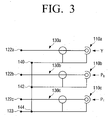
- FIG. 3 is a circuit diagram of the signal transfer apparatus of FIG. 1 .
- the invention relates to a signal transfer apparatus which transfers a plurality of signals from a first electronic device to a second electronic device.
- a signal transfer apparatus transfers a plurality of image signals output from a digital versatile disk (DVD) player or a set-top box corresponding to the first electronic device to a TV corresponding to the second electronic device in a component type signal transfer.
- DVD digital versatile disk
- embodiments are not limited to these electronic devices.
- embodiments may also be used to transfer audio signals or other signals other than image signals.
- the signal transfer apparatus 100 includes a plurality of input connectors 110a, 110b, 110c, a single output connector 120, and a plurality of cables 130a, 130b, 130c.
- the image signals are transferred as a component type in this exemplary embodiment.
- the signal transfer apparatus 100 includes the first input connector 110a to which a luminance signal Y is input, the second connector 110b to which a first color difference signal Pb is input, and the third connector 110c to which a second color difference signal Pr is input.
- the first electronic device (not shown) is connected to the plurality of input connectors 110a, 110b, 110c through external cables 111a, 111b, 111c, and the second electronic device (TV) 200 is connected to the output connector 120.
- three component signals Y, Pb, Pr are transferred three input connectors 110a, 110b, 110c are used.
- the number of input connectors is not limited thereto, and, if the number of signals to be transferred is increased or reduced, more or less input connectors may be used.
- the single output connector 120 is connected to all the input connectors 110a, 110b, 110c, and transfers the plurality of signals to the second electronic device, such as the TV 200.
- the number of input connectors 110a, 110b, 110c is plural, but only one output connector 120 is provided as shown in FIGS. 1 and 2 .
- the output connector 120 includes a plurality of signal regions 122a, 122b, 122c which are respectively connected to the cables 130a, 130b, 130c and receive the signals input to the input connectors 110a, 110b, 110c via the cables 130a, 130b, 130c. Accordingly, a single output connector 120 is used to transfer the plurality of signals.
- the TV 200 includes only one terminal 201 to receive the luminance signal Y and the first and second color difference signals Pb, Pr from the output connector 120, as shown in FIG. 2 . Because the TV 200 according to the invention requires a lesser number of terminals, e.g., only one terminal 201, the TV 200 may be miniaturized and/or slimmer.
- the cables 130a, 130b, 130c connects the single output connector 120 to the input connectors 110a, 110b, 110c.
- the length of each of the cables 130a, 130b, 130c differs from each other so that the input connectors 110a, 110b, 110c are staggered and do not overlap each other.
- the length of each of the cables 110a, 110b, 110c is successively longer than the next shortest cable.
- the length of the cables may be selected so that a difference in length between two cables is at least greater than a length of the input connectors 110a, 110b, 110c, or greater than a sum of the length of the input connectors 110a, 110b, 110c and a length of output connectors of the cables 111a, 111b, 111c coupled to the input connectors 110a, 110b and 110c.
- FIG. 2 illustrates the input connectors 110a, 110b, 110c which do not overlap each other.
- the input connectors 110a, 110b, 110c may overlap each other and thus the overlapped input connectors 110a, 110b, 110c may occupy a substantial volume behind the TV 200.
- the overlapped input connectors 110a, 110b, 110c may be disposed between a rear surface of the wall-mounted TV and a wall, and, thus, the overlapped input connectors 110a, 110b, 110c may occupy a substantial space between the rear surface and the wall. Accordingly, it may be difficult to closely attach the TV 200 to the wall.
- the wall-mounted TV may require more input connectors. That is, because the number of peripheral devices connected to the TV 200 may be increased, transfer of various signals such as audio signals other than image signals may be required. Even with a large number of input connectors, the signal transfer apparatus 100 according to the exemplary embodiment facilitates close attachment of the wall-mounted TV to the wall because the input connectors 110a, 110b, 110c do not overlap each other.
- the single output connector 120 includes an output terminal 121, the signal regions 122a, 122b, 122c, and a ground region 123.
- the output terminal 121 is inserted into the terminal 201 of the TV 200 to be connected to the TV 200, as shown in FIG. 2 . That is, the inserting direction of the output terminal 121 is parallel to a display plane of the TV 200. Accordingly, although the output terminal 121 is inserted into the terminal 201, the space between the rear surface of the TV 200 and the wall to accommodate the output connector 120 is minimized so that the TV 200 may be more closely attached to the wall.
- the output terminal 121 is formed in a pin shape as shown in FIG. 1 , but the output terminal 121 may be configured in various shapes.
- the signal regions 122a, 122b, 122c receive the signals from the input connectors 110a, 110b, 110c, respectively, via the cables 110a, 110b, 110c.
- the first signal region 122a receives and outputs the luminance signal Y through the first input connector 110a
- the second signal region 122b receives and outputs the first color difference signal Pb through the second input connector 110b
- the third signal region 122c receives and outputs the second color difference signal Pr through the third input connector 110c.
- the ground region 123 is connected to ground points 140, 142, 144 of the first, second, and third input connectors 110a, 110b, 110c, as shown in FIG. 3 .
- the first, second, and third signal regions 122a, 122b, 122c, and the ground region 123 are formed lengthwise along the output terminal 121 as shown in FIG. 1 . Accordingly, although only one output terminal 121 is provided, each signal Y, Pb, Pr is individually transferred to the TV 200.
- An insulating material 125 is disposed between the first, second, and third signal regions 122a, 122b, 122c and the ground region 123. The insulating material 125 obviates the plurality of signals from being jammed up.
- the plurality of signals Y, Pb, Pr is transferred to the TV 200 using a single output connector 120 so that the TV 200 needs only one terminal 201 to connect the output connector 120. Accordingly, the number of the terminals mounted to the TV 200 is reduced, and thus it allows the TV 200 to be miniaturized. Moreover, as the lengths of the plurality of cables 130a, 130b, 130c connecting the output connector 120 and the plurality of input connectors 110a, 110b, 110c differ from each other, the input connectors 110a, 110b, 110c do not overlap. Therefore, if the TV 200 according to an exemplary embodiment is a wall-mounted TV, the wall-mounted TV may be closely attached to the wall.
- the TV 200 according to an exemplary embodiment may be a light emitting diode (LED) TV, which is a substantially thin device.
- LED light emitting diode
Landscapes
- Engineering & Computer Science (AREA)
- Multimedia (AREA)
- Signal Processing (AREA)
- Details Of Connecting Devices For Male And Female Coupling (AREA)
- Coupling Device And Connection With Printed Circuit (AREA)
- Two-Way Televisions, Distribution Of Moving Picture Or The Like (AREA)
- Communication Cables (AREA)
- Cable Transmission Systems, Equalization Of Radio And Reduction Of Echo (AREA)
Description
- Apparatuses consistent with the invention relate to transferring signals, and more particularly, from an electronic device to another electronic device.
- Image signals or audio signals output from an electronic device need to be transferred to another electronic device to operate the electronic devices in association with each other. For example, image signals are transferred from a digital versatile disk (DVD) player or a set-top box to a television (TV) to reproduce the image signals. When an image signal is transferred as a component type, three component signals including a luminance signal Y and color difference signals Pb and Pr are transmitted to a TV, which includes terminals to receive such signals. There are various signal transfer methods other than a component type such as a composite type, and thus a TV should include various terminals to receive signals transferred in various manners.
- Recently, there have been many efforts to miniaturize electronic devices. For example, it may be necessary to miniaturize an electronic device to fabricate electronic devices such as a thin wall-mounted TV. For the miniaturized electronic devices, the size and number of terminals to transmit and receive signals to and from another electronic device need to be reduced.
- Additionally, the terminals are typically disposed on a rear surface of the electronic device. Electronic devices such as a wall-mounted TV are fixedly mounted on a wall. The wall-mounted TV includes cables to transfer audio signals or image signals and connectors to connect the wall-mounted TV to external devices, and these cables and connectors may make it difficult to closely attach the wall-mounted TV to the wall. Accordingly, there is a need for a connecter that facilitates close attachment of the wall-mounted TV to a wall.
-
WO2006/079958 mentions a TV with standard connectors for component video signals. The claims have been characterised over this document. -
US2008/045073 mentions a cable assembly,US2004/206528 mentions a connection cable,US6231379 mentions a VGA cable adapter,EP0854550 mentions a SCART cable adaptor,US6069960 mentions a connector for a stereo audio plug or an audio/video miniplug,US2009/156036 mentions a multimedia cable adaptable between a stereo audio plug or an audio/video miniplug. - According to the present invention there is provided an apparatus and method as set forth in the appended claims. Other features of the invention will be apparent from the dependent claims, and the description which follows.
- The above and other aspects will be more apparent by describing certain features with reference to the accompanying drawings, in which:
-
FIG. 1 is a schematic view of a signal transfer apparatus according to the invention; -
FIG. 2 is a schematic view of the signal transfer apparatus ofFIG. 1 coupled to an electronic device; and -
FIG. 3 is a circuit diagram of the signal transfer apparatus ofFIG. 1 . - In the following description, like drawing reference numerals are used for like elements, even in different drawings. The matters defined in the description, such as detailed construction and elements, are provided to assist in a comprehensive understanding of the invention. However, it is apparent that the present invention can be practiced without those specifically defined matters. Also, well-known functions or constructions are not described in detail since they would obscure the invention with unnecessary detail.
- The invention relates to a signal transfer apparatus which transfers a plurality of signals from a first electronic device to a second electronic device. In this exemplary embodiment, a signal transfer apparatus transfers a plurality of image signals output from a digital versatile disk (DVD) player or a set-top box corresponding to the first electronic device to a TV corresponding to the second electronic device in a component type signal transfer. However, embodiments are not limited to these electronic devices. In addition, embodiments may also be used to transfer audio signals or other signals other than image signals.
- The
signal transfer apparatus 100 according to the invention includes a plurality ofinput connectors single output connector 120, and a plurality ofcables - A plurality of signals output from the first electronic device, such as a DVD player or a set-top box, is input to the plurality of
input connectors signal transfer apparatus 100 includes thefirst input connector 110a to which a luminance signal Y is input, thesecond connector 110b to which a first color difference signal Pb is input, and thethird connector 110c to which a second color difference signal Pr is input. Referring toFIG. 2 , the first electronic device (not shown) is connected to the plurality ofinput connectors external cables output connector 120. - Because three component signals Y, Pb, Pr are transferred three
input connectors - The
single output connector 120 is connected to all theinput connectors TV 200. The number ofinput connectors output connector 120 is provided as shown inFIGS. 1 and2 . As described in detail below, theoutput connector 120 includes a plurality ofsignal regions cables input connectors cables single output connector 120 is used to transfer the plurality of signals. - Therefore, the
TV 200 includes only oneterminal 201 to receive the luminance signal Y and the first and second color difference signals Pb, Pr from theoutput connector 120, as shown inFIG. 2 . Because theTV 200 according to the invention requires a lesser number of terminals, e.g., only oneterminal 201, theTV 200 may be miniaturized and/or slimmer. - The
cables single output connector 120 to theinput connectors FIG. 1 , the length of each of thecables input connectors input connectors cables input connectors input connectors cables input connectors FIG. 2 illustrates theinput connectors - If the length of the
cables input connectors input connectors TV 200. For example, if theTV 200 is a wall-mounted TV, the overlappedinput connectors input connectors TV 200 to the wall. Although only threeinput connectors TV 200 may be increased, transfer of various signals such as audio signals other than image signals may be required. Even with a large number of input connectors, thesignal transfer apparatus 100 according to the exemplary embodiment facilitates close attachment of the wall-mounted TV to the wall because theinput connectors - Referring to
FIG. 1 , thesingle output connector 120 includes anoutput terminal 121, thesignal regions ground region 123. - The
output terminal 121 is inserted into theterminal 201 of theTV 200 to be connected to theTV 200, as shown inFIG. 2 . That is, the inserting direction of theoutput terminal 121 is parallel to a display plane of theTV 200. Accordingly, although theoutput terminal 121 is inserted into theterminal 201, the space between the rear surface of theTV 200 and the wall to accommodate theoutput connector 120 is minimized so that theTV 200 may be more closely attached to the wall. Theoutput terminal 121 is formed in a pin shape as shown inFIG. 1 , but theoutput terminal 121 may be configured in various shapes. - The
signal regions input connectors cables FIG. 3 , thefirst signal region 122a receives and outputs the luminance signal Y through thefirst input connector 110a, thesecond signal region 122b receives and outputs the first color difference signal Pb through thesecond input connector 110b, and thethird signal region 122c receives and outputs the second color difference signal Pr through thethird input connector 110c. - The
ground region 123 is connected to groundpoints third input connectors FIG. 3 . - The first, second, and
third signal regions ground region 123 are formed lengthwise along theoutput terminal 121 as shown inFIG. 1 . Accordingly, although only oneoutput terminal 121 is provided, each signal Y, Pb, Pr is individually transferred to theTV 200. An insulatingmaterial 125 is disposed between the first, second, andthird signal regions ground region 123. The insulatingmaterial 125 obviates the plurality of signals from being jammed up. - According to the invention as described above, the plurality of signals Y, Pb, Pr is transferred to the
TV 200 using asingle output connector 120 so that theTV 200 needs only oneterminal 201 to connect theoutput connector 120. Accordingly, the number of the terminals mounted to theTV 200 is reduced, and thus it allows theTV 200 to be miniaturized. Moreover, as the lengths of the plurality ofcables output connector 120 and the plurality ofinput connectors input connectors TV 200 according to an exemplary embodiment is a wall-mounted TV, the wall-mounted TV may be closely attached to the wall. TheTV 200 according to an exemplary embodiment may be a light emitting diode (LED) TV, which is a substantially thin device. - The foregoing exemplary embodiments and advantages are merely exemplary and are not to be construed as limiting the present invention. The present teaching can be readily applied to other types of apparatuses. Also, the description of the exemplary embodiments is intended to be illustrative, and not to limit the scope of the claims, and many alternatives, modifications, and variations will be apparent to those skilled in the art.
Claims (12)
- An electronic device such as a TV (200), comprising:an input terminal (201) provided on a rear side of a housing of the TV (200); anda cable assembly (100) having an output terminal (121) which is inserted in use into the input terminal (201);characterised in that:the cable assembly (100) includes:a first input connector (110a) to receive a luminance signal,a second input connector (110b) to receive a first color difference signal,a third input connector (110c) to receive a second color difference signal, andan output terminal (121) having a first signal region (122a) to output the luminance signal, a second signal region (122b) to output the first color difference signal, and a third signal region (122c) to output the second color difference signal; andwherein the output terminal (121) is a single pin shaped output terminal comprising a base and a tip which is disposed opposite to the base and is insertable into the input terminal (201) of the TV (200),wherein the first signal region (122a), the second signal region (122b), and the third signal region (122c) are sequentially formed lengthwise, in this order, from the tip to the base along the single pin-shaped output terminal (121), andwherein the input terminal (201) of the TV (200) is adapted to connect with the single pin shaped output terminal (121) of the cable assembly (100) to receive the luminance signal and the first and second color difference signals via the cable assembly (100).
- The electronic apparatus as claimed in claim 1, wherein the rear side of the housing has a recessed region, and
the input terminal (201) is disposed in the recessed region parallel to a display plane of the TV (200) such that single pin shaped output terminal (121) is inserted by pushing parallel to the display plane of the TV (200) into the input terminal (201). - The electronic apparatus as claimed in claim 1, wherein the rear side of the housing has a recessed region, and
at least a portion of the input terminal (201) is located at the recessed region such that at least a portion of the single pin shaped output terminal (121) and cables extending therefrom (130) is disposed within the recessed region when the cable assembly is connected to the input terminal. - The electronic apparatus as claimed in claim 1, wherein the cable assembly comprises a plurality of cables (130) disposed between the single pin shaped output terminal (121) and the input connectors (110), wherein each of the plurality of cables (130) have a length which differs from the lengths of the other cables of the plurality cables so that the input connectors (110) do not overlap each other.
- The electronic apparatus as claimed in claim 1, wherein the pin shaped output terminal (121) further comprises a ground region (123) which is connected to ground points of the plurality of input connectors (110).
- The electronic apparatus as claimed in claim 5, wherein the first signal region (122a), the second signal region (122b), the third signal region (122c) and the ground region (123) are sequentially provided along lengthwise of the single pin shaped output terminal (121), and an insulating material (125) is disposed between each of the signal regions (122) and the ground region (123).
- A method comprising:providing a cable assembly including a first input connector (110a), a second input connector (110b), a third input connector (110c), and an output terminal (121);connecting the output terminal (121) of the cable assembly into an input terminal (201) provided on a rear side of a housing of a TV (200);receiving luminance signal via a first input connector (110a) of the cable assembly;receiving first color difference signal via a second input connector (110b) of the cable assembly; and treceiving second color difference signal via a third input connector (110c) of the cable assembly,wherein the output terminal (121) has a first signal region (122a) to output the luminance signal, a second signal region (122b) to output the first color difference signal, and a third signal region (122c) to output the second color difference signal,wherein the output terminal (121) is a single pin shaped output terminal comprising a base and a tip which is disposed opposite to the base and is insertable into the input terminal (201) of the TV (200), andwherein the first signal region (122a), the second signal region (122b), and the third signal region (122c) are sequentially formed lengthwise, in this order, from the tip to the base along the single pin-shaped output terminal.
- The method as claimed in claim 7, wherein the rear side of the housing has a recessed region, and the input terminal (201) is disposed in the recessed region parallel to a display plane of the TV (200),
wherein the step of connecting the single pin shaped output terminal (121) to the TV (200) comprises inserting the single pin shaped output terminal (121) parallel to the display plane of the TV (200) into the input terminal (201). - The method as claimed in claim 8, wherein at least a portion of the single pin shaped output terminal (121) and cables extending therefrom (130) is disposed within the recessed region at the rear side of the housing when the cable assembly is connected to the input terminal (201).
- The method as claimed in claim 7, wherein the cable assembly comprises a plurality of cables (130) disposed between the single pin shaped output terminal (121) and the input connectors (110), wherein each of the plurality of cables (130) have a length which differs from the lengths of the other cables of the plurality cables (130) so that the input connectors (110) do not overlap each other.
- The method as claimed in claim 7, wherein the pin shaped output terminal (121) further comprises a ground region (123) which is connected to ground points of the plurality of input connectors.
- The method as claimed in claim 11, wherein the first signal region (122a), the second signal region (122b), the third signal region (122c) and the ground region (123) are sequentially provided along lengthwise of the single pin shaped output terminal (121), and
an insulating material (125) is disposed between each of the signal regions (122) and the ground region (123).
Priority Applications (1)
| Application Number | Priority Date | Filing Date | Title |
|---|---|---|---|
| EP15158491.9A EP2897237B1 (en) | 2009-03-12 | 2009-10-30 | Signal transfer apparatus |
Applications Claiming Priority (1)
| Application Number | Priority Date | Filing Date | Title |
|---|---|---|---|
| KR1020090021271A KR101352788B1 (en) | 2009-03-12 | 2009-03-12 | Signal transmission device |
Related Child Applications (2)
| Application Number | Title | Priority Date | Filing Date |
|---|---|---|---|
| EP15158491.9A Division-Into EP2897237B1 (en) | 2009-03-12 | 2009-10-30 | Signal transfer apparatus |
| EP15158491.9A Division EP2897237B1 (en) | 2009-03-12 | 2009-10-30 | Signal transfer apparatus |
Publications (3)
| Publication Number | Publication Date |
|---|---|
| EP2228873A2 EP2228873A2 (en) | 2010-09-15 |
| EP2228873A3 EP2228873A3 (en) | 2012-10-31 |
| EP2228873B1 true EP2228873B1 (en) | 2015-04-22 |
Family
ID=41718470
Family Applications (2)
| Application Number | Title | Priority Date | Filing Date |
|---|---|---|---|
| EP15158491.9A Active EP2897237B1 (en) | 2009-03-12 | 2009-10-30 | Signal transfer apparatus |
| EP20090174577 Active EP2228873B1 (en) | 2009-03-12 | 2009-10-30 | Signal transfer apparatus |
Family Applications Before (1)
| Application Number | Title | Priority Date | Filing Date |
|---|---|---|---|
| EP15158491.9A Active EP2897237B1 (en) | 2009-03-12 | 2009-10-30 | Signal transfer apparatus |
Country Status (4)
| Country | Link |
|---|---|
| US (4) | US8710370B2 (en) |
| EP (2) | EP2897237B1 (en) |
| KR (1) | KR101352788B1 (en) |
| HU (1) | HUE024998T2 (en) |
Families Citing this family (9)
| Publication number | Priority date | Publication date | Assignee | Title |
|---|---|---|---|---|
| KR101352788B1 (en) | 2009-03-12 | 2014-01-16 | 삼성전자주식회사 | Signal transmission device |
| US8690595B2 (en) | 2012-06-25 | 2014-04-08 | Cooper Technologies Company | Squid connector with coupling feature |
| US10170092B2 (en) * | 2013-05-08 | 2019-01-01 | Gerard Mayo | Pedal board connection system for musical instruments |
| AU2013270633A1 (en) * | 2013-05-08 | 2014-12-18 | Mayo, Gerard Peter MR | Pedal Board and Pedal Board Connection System |
| EP3185568A1 (en) | 2015-12-23 | 2017-06-28 | Samsung Electronics Co., Ltd. | Display apparatus and control method for connecting external sources |
| US11056252B2 (en) * | 2018-07-19 | 2021-07-06 | Douglas W Schroeder | Electrical signal transmission cable system and method of using same |
| JP7301609B2 (en) * | 2019-06-05 | 2023-07-03 | 東芝テック株式会社 | communication cable |
| FR3126807B1 (en) | 2021-09-07 | 2023-07-21 | Karim Messadek | audio file |
| US12374840B1 (en) * | 2023-12-13 | 2025-07-29 | Gregory A Wadleigh | Signal-modifying audio patch cable that intercepts studio voices from surround sound |
Citations (2)
| Publication number | Priority date | Publication date | Assignee | Title |
|---|---|---|---|---|
| US6069960A (en) * | 1996-09-05 | 2000-05-30 | Sony Corporation | Connector device for information-handling apparatus and connector device for stereophonic audio/video apparatus |
| WO2006079958A1 (en) * | 2005-01-26 | 2006-08-03 | Koninklijke Philips Electronics N.V. | Television set |
Family Cites Families (26)
| Publication number | Priority date | Publication date | Assignee | Title |
|---|---|---|---|---|
| JPH03280365A (en) * | 1990-03-28 | 1991-12-11 | Yazaki Corp | Waterproof seal structure of wire harness |
| IT222996Z2 (en) * | 1990-10-10 | 1995-05-12 | Mortara Rangoni Europ S R L | MULTI-POLE PLATEN CONNECTION CABLE, MULTI-SCREENED, ESPECIALLY FOR ELECTROCARDIOGRAPHS OR OTHER MEASURING INSTRUMENTS |
| US5546950A (en) * | 1994-07-06 | 1996-08-20 | Mortara Instrument, Inc. | Electrocardiograpic patient lead cable apparatus |
| US5547399A (en) * | 1995-02-27 | 1996-08-20 | Naghi; Herschel | Universal AC adaptor for consumer electronics |
| US5790896A (en) * | 1996-06-24 | 1998-08-04 | The United States Of America As Represented By The Secretary Of The Navy | Apparatus for a testing system with a plurality of first connection having a structural characteristic and a plurality of second connection having a different structural characteristic than the first connection |
| US5937950A (en) * | 1996-12-02 | 1999-08-17 | Medex, Inc. | Cable system for medical equipment |
| JPH10208830A (en) | 1997-01-20 | 1998-08-07 | Sony Corp | Adapters and connectors for connectors |
| US6169879B1 (en) * | 1998-09-16 | 2001-01-02 | Webtv Networks, Inc. | System and method of interconnecting and using components of home entertainment system |
| US6829779B1 (en) * | 1998-09-16 | 2004-12-07 | Webtv Networks, Inc. | User interface for entertainment system setup |
| US6231379B1 (en) | 1999-12-28 | 2001-05-15 | Innmaging Quality Technology, Inc. | VGA cable adapter for transmitting video signals |
| JP4780367B2 (en) | 2001-09-06 | 2011-09-28 | ソニー株式会社 | Multi plug and multi jack |
| KR200270456Y1 (en) * | 2001-12-28 | 2002-04-04 | 주식회사 스탠더드텔레콤 | USB Cable Using Earphone Jack Interface |
| US6800810B1 (en) * | 2002-09-03 | 2004-10-05 | William Jody Page | Snake for musical instrument wiring |
| AU2003901297A0 (en) * | 2003-03-20 | 2003-04-03 | Silverbrook Research Pty Ltd | Systems and apparatus (fpd001) |
| TWI221043B (en) * | 2003-04-17 | 2004-09-11 | Benq Corp | Connection wire |
| JP4426222B2 (en) * | 2003-07-10 | 2010-03-03 | 興和株式会社 | Cable extension device |
| WO2006027640A1 (en) * | 2004-09-10 | 2006-03-16 | Nokia Corporation | Audio and video plug and socket having integrated video contact |
| KR20060030147A (en) * | 2004-10-05 | 2006-04-10 | 엘지전자 주식회사 | Signal transmission device of electronic device |
| JP2006331842A (en) | 2005-05-26 | 2006-12-07 | Seiko Epson Corp | Connection cable and projector |
| KR100802132B1 (en) * | 2005-12-12 | 2008-02-11 | 삼성전자주식회사 | Connecting cable |
| JP4910418B2 (en) | 2006-02-22 | 2012-04-04 | 住友電気工業株式会社 | Manufacturing method of multi-core cable |
| US7521634B2 (en) * | 2006-05-19 | 2009-04-21 | Tektronix, Inc. | Multi-Channel signal acquisition probe |
| CN200959418Y (en) * | 2006-08-18 | 2007-10-10 | 富士康(昆山)电脑接插件有限公司 | cable combination |
| KR100999140B1 (en) * | 2007-12-18 | 2010-12-08 | 현대자동차주식회사 | 3-pole or 4-pole switchable multimedia jack cable |
| KR101352788B1 (en) | 2009-03-12 | 2014-01-16 | 삼성전자주식회사 | Signal transmission device |
| KR20130024941A (en) | 2013-01-29 | 2013-03-08 | 삼성전자주식회사 | Signal transfer apparatus |
-
2009
- 2009-03-12 KR KR1020090021271A patent/KR101352788B1/en active Active
- 2009-10-28 US US12/607,146 patent/US8710370B2/en active Active
- 2009-10-30 EP EP15158491.9A patent/EP2897237B1/en active Active
- 2009-10-30 EP EP20090174577 patent/EP2228873B1/en active Active
- 2009-10-30 HU HUE09174577A patent/HUE024998T2/en unknown
-
2012
- 2012-05-11 US US13/469,901 patent/US9118877B2/en active Active
-
2014
- 2014-02-25 US US14/188,930 patent/US8895855B2/en active Active
- 2014-10-14 US US14/514,172 patent/US9282276B2/en active Active
Patent Citations (2)
| Publication number | Priority date | Publication date | Assignee | Title |
|---|---|---|---|---|
| US6069960A (en) * | 1996-09-05 | 2000-05-30 | Sony Corporation | Connector device for information-handling apparatus and connector device for stereophonic audio/video apparatus |
| WO2006079958A1 (en) * | 2005-01-26 | 2006-08-03 | Koninklijke Philips Electronics N.V. | Television set |
Also Published As
| Publication number | Publication date |
|---|---|
| US8710370B2 (en) | 2014-04-29 |
| US9118877B2 (en) | 2015-08-25 |
| US9282276B2 (en) | 2016-03-08 |
| EP2897237B1 (en) | 2017-12-27 |
| EP2228873A2 (en) | 2010-09-15 |
| US20140168528A1 (en) | 2014-06-19 |
| HUE024998T2 (en) | 2016-01-28 |
| EP2897237A1 (en) | 2015-07-22 |
| EP2228873A3 (en) | 2012-10-31 |
| US8895855B2 (en) | 2014-11-25 |
| KR101352788B1 (en) | 2014-01-16 |
| US20120225580A1 (en) | 2012-09-06 |
| KR20100102942A (en) | 2010-09-27 |
| US20100230159A1 (en) | 2010-09-16 |
| US20150029399A1 (en) | 2015-01-29 |
Similar Documents
| Publication | Publication Date | Title |
|---|---|---|
| EP2228873B1 (en) | Signal transfer apparatus | |
| US7934959B2 (en) | Adapter for pluggable module | |
| US7488187B2 (en) | Dual channel XLR cable converter | |
| US9374642B2 (en) | Multipurpose connector for multiplexing headset interface into high-definition video and audio interface, and handheld electronic device | |
| US7744428B2 (en) | Audio signal switcher | |
| US20060154530A1 (en) | Connector system | |
| JP2007103301A (en) | Electrical connector | |
| CN201044293Y (en) | High definition multimedia interface connector assembly | |
| CN113810070B (en) | Signal transmission device capable of transmitting multiple sets of data streams | |
| US20210399925A1 (en) | Signal transmission device capable of transmitting multiple data streams | |
| US8907221B1 (en) | Reinforced intelligent cables | |
| US20040206528A1 (en) | Connection cable | |
| US7259949B2 (en) | Method and system for ESD protection of balanced circuit board lines | |
| KR20130024941A (en) | Signal transfer apparatus | |
| KR200456546Y1 (en) | Connection cable for vehicles | |
| US20130278833A1 (en) | Set back box | |
| KR101170460B1 (en) | External device connecting muti-port for camera | |
| KR200333562Y1 (en) | display apparatus | |
| US20120003876A1 (en) | Hdmi connector | |
| KR20020088168A (en) | A multi interface apparatus of mobile phone | |
| JP2006269383A (en) | Multi-cable and multi-jack | |
| KR20110139015A (en) | HDMD interface | |
| US20160211631A1 (en) | High-speed signal transmission device | |
| KR20060030147A (en) | Signal transmission device of electronic device | |
| KR20070096087A (en) | Connecting cable |
Legal Events
| Date | Code | Title | Description |
|---|---|---|---|
| PUAI | Public reference made under article 153(3) epc to a published international application that has entered the european phase |
Free format text: ORIGINAL CODE: 0009012 |
|
| AK | Designated contracting states |
Kind code of ref document: A2 Designated state(s): AT BE BG CH CY CZ DE DK EE ES FI FR GB GR HR HU IE IS IT LI LT LU LV MC MK MT NL NO PL PT RO SE SI SK SM TR |
|
| AX | Request for extension of the european patent |
Extension state: AL BA RS |
|
| RAP1 | Party data changed (applicant data changed or rights of an application transferred) |
Owner name: SAMSUNG ELECTRONICS CO., LTD. |
|
| PUAL | Search report despatched |
Free format text: ORIGINAL CODE: 0009013 |
|
| AK | Designated contracting states |
Kind code of ref document: A3 Designated state(s): AT BE BG CH CY CZ DE DK EE ES FI FR GB GR HR HU IE IS IT LI LT LU LV MC MK MT NL NO PL PT RO SE SI SK SM TR |
|
| AX | Request for extension of the european patent |
Extension state: AL BA RS |
|
| RIC1 | Information provided on ipc code assigned before grant |
Ipc: H01R 31/06 20060101ALI20120926BHEP Ipc: H01R 31/00 20060101AFI20120926BHEP |
|
| 17P | Request for examination filed |
Effective date: 20130325 |
|
| 17Q | First examination report despatched |
Effective date: 20130715 |
|
| RIC1 | Information provided on ipc code assigned before grant |
Ipc: H01R 31/00 20060101ALI20140805BHEP Ipc: H01R 24/58 20110101AFI20140805BHEP Ipc: H01R 31/06 20060101ALI20140805BHEP Ipc: H01R 31/02 20060101ALN20140805BHEP |
|
| REG | Reference to a national code |
Ref country code: DE Ref legal event code: R079 Ref document number: 602009030758 Country of ref document: DE Free format text: PREVIOUS MAIN CLASS: H01R0031000000 Ipc: H01R0024580000 |
|
| GRAP | Despatch of communication of intention to grant a patent |
Free format text: ORIGINAL CODE: EPIDOSNIGR1 |
|
| RIC1 | Information provided on ipc code assigned before grant |
Ipc: H01R 31/06 20060101ALI20150204BHEP Ipc: H01R 31/00 20060101ALI20150204BHEP Ipc: H01R 31/02 20060101ALN20150204BHEP Ipc: H01R 24/58 20110101AFI20150204BHEP |
|
| GRAS | Grant fee paid |
Free format text: ORIGINAL CODE: EPIDOSNIGR3 |
|
| INTG | Intention to grant announced |
Effective date: 20150220 |
|
| RIC1 | Information provided on ipc code assigned before grant |
Ipc: H01R 24/58 20110101AFI20150206BHEP Ipc: H01R 31/06 20060101ALI20150206BHEP Ipc: H01R 31/00 20060101ALI20150206BHEP Ipc: H01R 31/02 20060101ALN20150206BHEP |
|
| GRAA | (expected) grant |
Free format text: ORIGINAL CODE: 0009210 |
|
| AK | Designated contracting states |
Kind code of ref document: B1 Designated state(s): AT BE BG CH CY CZ DE DK EE ES FI FR GB GR HR HU IE IS IT LI LT LU LV MC MK MT NL NO PL PT RO SE SI SK SM TR |
|
| REG | Reference to a national code |
Ref country code: GB Ref legal event code: FG4D |
|
| REG | Reference to a national code |
Ref country code: CH Ref legal event code: EP |
|
| REG | Reference to a national code |
Ref country code: AT Ref legal event code: REF Ref document number: 723749 Country of ref document: AT Kind code of ref document: T Effective date: 20150515 |
|
| REG | Reference to a national code |
Ref country code: IE Ref legal event code: FG4D |
|
| REG | Reference to a national code |
Ref country code: DE Ref legal event code: R096 Ref document number: 602009030758 Country of ref document: DE Effective date: 20150603 |
|
| REG | Reference to a national code |
Ref country code: NL Ref legal event code: T3 |
|
| REG | Reference to a national code |
Ref country code: NL Ref legal event code: T3 |
|
| REG | Reference to a national code |
Ref country code: AT Ref legal event code: MK05 Ref document number: 723749 Country of ref document: AT Kind code of ref document: T Effective date: 20150422 |
|
| REG | Reference to a national code |
Ref country code: LT Ref legal event code: MG4D |
|
| REG | Reference to a national code |
Ref country code: FR Ref legal event code: PLFP Year of fee payment: 7 |
|
| PG25 | Lapsed in a contracting state [announced via postgrant information from national office to epo] |
Ref country code: LT Free format text: LAPSE BECAUSE OF FAILURE TO SUBMIT A TRANSLATION OF THE DESCRIPTION OR TO PAY THE FEE WITHIN THE PRESCRIBED TIME-LIMIT Effective date: 20150422 Ref country code: PT Free format text: LAPSE BECAUSE OF FAILURE TO SUBMIT A TRANSLATION OF THE DESCRIPTION OR TO PAY THE FEE WITHIN THE PRESCRIBED TIME-LIMIT Effective date: 20150824 Ref country code: NO Free format text: LAPSE BECAUSE OF FAILURE TO SUBMIT A TRANSLATION OF THE DESCRIPTION OR TO PAY THE FEE WITHIN THE PRESCRIBED TIME-LIMIT Effective date: 20150722 Ref country code: ES Free format text: LAPSE BECAUSE OF FAILURE TO SUBMIT A TRANSLATION OF THE DESCRIPTION OR TO PAY THE FEE WITHIN THE PRESCRIBED TIME-LIMIT Effective date: 20150422 Ref country code: FI Free format text: LAPSE BECAUSE OF FAILURE TO SUBMIT A TRANSLATION OF THE DESCRIPTION OR TO PAY THE FEE WITHIN THE PRESCRIBED TIME-LIMIT Effective date: 20150422 Ref country code: HR Free format text: LAPSE BECAUSE OF FAILURE TO SUBMIT A TRANSLATION OF THE DESCRIPTION OR TO PAY THE FEE WITHIN THE PRESCRIBED TIME-LIMIT Effective date: 20150422 |
|
| REG | Reference to a national code |
Ref country code: SK Ref legal event code: T3 Ref document number: E 19004 Country of ref document: SK |
|
| PG25 | Lapsed in a contracting state [announced via postgrant information from national office to epo] |
Ref country code: GR Free format text: LAPSE BECAUSE OF FAILURE TO SUBMIT A TRANSLATION OF THE DESCRIPTION OR TO PAY THE FEE WITHIN THE PRESCRIBED TIME-LIMIT Effective date: 20150723 Ref country code: AT Free format text: LAPSE BECAUSE OF FAILURE TO SUBMIT A TRANSLATION OF THE DESCRIPTION OR TO PAY THE FEE WITHIN THE PRESCRIBED TIME-LIMIT Effective date: 20150422 Ref country code: IS Free format text: LAPSE BECAUSE OF FAILURE TO SUBMIT A TRANSLATION OF THE DESCRIPTION OR TO PAY THE FEE WITHIN THE PRESCRIBED TIME-LIMIT Effective date: 20150822 Ref country code: LV Free format text: LAPSE BECAUSE OF FAILURE TO SUBMIT A TRANSLATION OF THE DESCRIPTION OR TO PAY THE FEE WITHIN THE PRESCRIBED TIME-LIMIT Effective date: 20150422 |
|
| REG | Reference to a national code |
Ref country code: DE Ref legal event code: R097 Ref document number: 602009030758 Country of ref document: DE |
|
| REG | Reference to a national code |
Ref country code: HU Ref legal event code: AG4A Ref document number: E024998 Country of ref document: HU |
|
| PG25 | Lapsed in a contracting state [announced via postgrant information from national office to epo] |
Ref country code: DK Free format text: LAPSE BECAUSE OF FAILURE TO SUBMIT A TRANSLATION OF THE DESCRIPTION OR TO PAY THE FEE WITHIN THE PRESCRIBED TIME-LIMIT Effective date: 20150422 Ref country code: EE Free format text: LAPSE BECAUSE OF FAILURE TO SUBMIT A TRANSLATION OF THE DESCRIPTION OR TO PAY THE FEE WITHIN THE PRESCRIBED TIME-LIMIT Effective date: 20150422 |
|
| PLBE | No opposition filed within time limit |
Free format text: ORIGINAL CODE: 0009261 |
|
| STAA | Information on the status of an ep patent application or granted ep patent |
Free format text: STATUS: NO OPPOSITION FILED WITHIN TIME LIMIT |
|
| PG25 | Lapsed in a contracting state [announced via postgrant information from national office to epo] |
Ref country code: PL Free format text: LAPSE BECAUSE OF FAILURE TO SUBMIT A TRANSLATION OF THE DESCRIPTION OR TO PAY THE FEE WITHIN THE PRESCRIBED TIME-LIMIT Effective date: 20150422 Ref country code: CZ Free format text: LAPSE BECAUSE OF FAILURE TO SUBMIT A TRANSLATION OF THE DESCRIPTION OR TO PAY THE FEE WITHIN THE PRESCRIBED TIME-LIMIT Effective date: 20150422 Ref country code: RO Free format text: LAPSE BECAUSE OF NON-PAYMENT OF DUE FEES Effective date: 20150422 |
|
| 26N | No opposition filed |
Effective date: 20160125 |
|
| PG25 | Lapsed in a contracting state [announced via postgrant information from national office to epo] |
Ref country code: IT Free format text: LAPSE BECAUSE OF FAILURE TO SUBMIT A TRANSLATION OF THE DESCRIPTION OR TO PAY THE FEE WITHIN THE PRESCRIBED TIME-LIMIT Effective date: 20150422 |
|
| PG25 | Lapsed in a contracting state [announced via postgrant information from national office to epo] |
Ref country code: LU Free format text: LAPSE BECAUSE OF FAILURE TO SUBMIT A TRANSLATION OF THE DESCRIPTION OR TO PAY THE FEE WITHIN THE PRESCRIBED TIME-LIMIT Effective date: 20151030 Ref country code: SI Free format text: LAPSE BECAUSE OF FAILURE TO SUBMIT A TRANSLATION OF THE DESCRIPTION OR TO PAY THE FEE WITHIN THE PRESCRIBED TIME-LIMIT Effective date: 20150422 |
|
| REG | Reference to a national code |
Ref country code: CH Ref legal event code: PL |
|
| PG25 | Lapsed in a contracting state [announced via postgrant information from national office to epo] |
Ref country code: MC Free format text: LAPSE BECAUSE OF FAILURE TO SUBMIT A TRANSLATION OF THE DESCRIPTION OR TO PAY THE FEE WITHIN THE PRESCRIBED TIME-LIMIT Effective date: 20150422 |
|
| REG | Reference to a national code |
Ref country code: IE Ref legal event code: MM4A |
|
| PG25 | Lapsed in a contracting state [announced via postgrant information from national office to epo] |
Ref country code: CH Free format text: LAPSE BECAUSE OF NON-PAYMENT OF DUE FEES Effective date: 20151031 Ref country code: LI Free format text: LAPSE BECAUSE OF NON-PAYMENT OF DUE FEES Effective date: 20151031 |
|
| PG25 | Lapsed in a contracting state [announced via postgrant information from national office to epo] |
Ref country code: BE Free format text: LAPSE BECAUSE OF FAILURE TO SUBMIT A TRANSLATION OF THE DESCRIPTION OR TO PAY THE FEE WITHIN THE PRESCRIBED TIME-LIMIT Effective date: 20150422 |
|
| REG | Reference to a national code |
Ref country code: FR Ref legal event code: PLFP Year of fee payment: 8 |
|
| PG25 | Lapsed in a contracting state [announced via postgrant information from national office to epo] |
Ref country code: IE Free format text: LAPSE BECAUSE OF NON-PAYMENT OF DUE FEES Effective date: 20151030 |
|
| PG25 | Lapsed in a contracting state [announced via postgrant information from national office to epo] |
Ref country code: BG Free format text: LAPSE BECAUSE OF FAILURE TO SUBMIT A TRANSLATION OF THE DESCRIPTION OR TO PAY THE FEE WITHIN THE PRESCRIBED TIME-LIMIT Effective date: 20150422 Ref country code: SM Free format text: LAPSE BECAUSE OF FAILURE TO SUBMIT A TRANSLATION OF THE DESCRIPTION OR TO PAY THE FEE WITHIN THE PRESCRIBED TIME-LIMIT Effective date: 20150422 |
|
| PG25 | Lapsed in a contracting state [announced via postgrant information from national office to epo] |
Ref country code: SE Free format text: LAPSE BECAUSE OF FAILURE TO SUBMIT A TRANSLATION OF THE DESCRIPTION OR TO PAY THE FEE WITHIN THE PRESCRIBED TIME-LIMIT Effective date: 20150422 Ref country code: CY Free format text: LAPSE BECAUSE OF FAILURE TO SUBMIT A TRANSLATION OF THE DESCRIPTION OR TO PAY THE FEE WITHIN THE PRESCRIBED TIME-LIMIT Effective date: 20150422 |
|
| PG25 | Lapsed in a contracting state [announced via postgrant information from national office to epo] |
Ref country code: MT Free format text: LAPSE BECAUSE OF FAILURE TO SUBMIT A TRANSLATION OF THE DESCRIPTION OR TO PAY THE FEE WITHIN THE PRESCRIBED TIME-LIMIT Effective date: 20150422 |
|
| REG | Reference to a national code |
Ref country code: FR Ref legal event code: PLFP Year of fee payment: 9 |
|
| PG25 | Lapsed in a contracting state [announced via postgrant information from national office to epo] |
Ref country code: MK Free format text: LAPSE BECAUSE OF FAILURE TO SUBMIT A TRANSLATION OF THE DESCRIPTION OR TO PAY THE FEE WITHIN THE PRESCRIBED TIME-LIMIT Effective date: 20150422 |
|
| REG | Reference to a national code |
Ref country code: FR Ref legal event code: PLFP Year of fee payment: 10 |
|
| PGFP | Annual fee paid to national office [announced via postgrant information from national office to epo] |
Ref country code: NL Payment date: 20250922 Year of fee payment: 17 Ref country code: TR Payment date: 20250911 Year of fee payment: 17 |
|
| PGFP | Annual fee paid to national office [announced via postgrant information from national office to epo] |
Ref country code: GB Payment date: 20250922 Year of fee payment: 17 |
|
| PGFP | Annual fee paid to national office [announced via postgrant information from national office to epo] |
Ref country code: FR Payment date: 20250925 Year of fee payment: 17 |
|
| PGFP | Annual fee paid to national office [announced via postgrant information from national office to epo] |
Ref country code: SK Payment date: 20250918 Year of fee payment: 17 |
|
| PGFP | Annual fee paid to national office [announced via postgrant information from national office to epo] |
Ref country code: HU Payment date: 20251029 Year of fee payment: 17 |
|
| PGFP | Annual fee paid to national office [announced via postgrant information from national office to epo] |
Ref country code: DE Payment date: 20250922 Year of fee payment: 17 |