EP2228851A1 - Battery housing formed with cooling passages and battery pack having the same - Google Patents
Battery housing formed with cooling passages and battery pack having the same Download PDFInfo
- Publication number
- EP2228851A1 EP2228851A1 EP20090171611 EP09171611A EP2228851A1 EP 2228851 A1 EP2228851 A1 EP 2228851A1 EP 20090171611 EP20090171611 EP 20090171611 EP 09171611 A EP09171611 A EP 09171611A EP 2228851 A1 EP2228851 A1 EP 2228851A1
- Authority
- EP
- European Patent Office
- Prior art keywords
- housing
- cooling passages
- battery pack
- battery
- cap plate
- Prior art date
- Legal status (The legal status is an assumption and is not a legal conclusion. Google has not performed a legal analysis and makes no representation as to the accuracy of the status listed.)
- Granted
Links
Images




Classifications
-
- H—ELECTRICITY
- H01—ELECTRIC ELEMENTS
- H01M—PROCESSES OR MEANS, e.g. BATTERIES, FOR THE DIRECT CONVERSION OF CHEMICAL ENERGY INTO ELECTRICAL ENERGY
- H01M50/00—Constructional details or processes of manufacture of the non-active parts of electrochemical cells other than fuel cells, e.g. hybrid cells
- H01M50/20—Mountings; Secondary casings or frames; Racks, modules or packs; Suspension devices; Shock absorbers; Transport or carrying devices; Holders
- H01M50/233—Mountings; Secondary casings or frames; Racks, modules or packs; Suspension devices; Shock absorbers; Transport or carrying devices; Holders characterised by physical properties of casings or racks, e.g. dimensions
- H01M50/24—Mountings; Secondary casings or frames; Racks, modules or packs; Suspension devices; Shock absorbers; Transport or carrying devices; Holders characterised by physical properties of casings or racks, e.g. dimensions adapted for protecting batteries from their environment, e.g. from corrosion
-
- H—ELECTRICITY
- H01—ELECTRIC ELEMENTS
- H01M—PROCESSES OR MEANS, e.g. BATTERIES, FOR THE DIRECT CONVERSION OF CHEMICAL ENERGY INTO ELECTRICAL ENERGY
- H01M10/00—Secondary cells; Manufacture thereof
- H01M10/60—Heating or cooling; Temperature control
- H01M10/65—Means for temperature control structurally associated with the cells
- H01M10/656—Means for temperature control structurally associated with the cells characterised by the type of heat-exchange fluid
- H01M10/6561—Gases
- H01M10/6566—Means within the gas flow to guide the flow around one or more cells, e.g. manifolds, baffles or other barriers
-
- H—ELECTRICITY
- H01—ELECTRIC ELEMENTS
- H01M—PROCESSES OR MEANS, e.g. BATTERIES, FOR THE DIRECT CONVERSION OF CHEMICAL ENERGY INTO ELECTRICAL ENERGY
- H01M10/00—Secondary cells; Manufacture thereof
- H01M10/04—Construction or manufacture in general
- H01M10/0431—Cells with wound or folded electrodes
-
- H—ELECTRICITY
- H01—ELECTRIC ELEMENTS
- H01M—PROCESSES OR MEANS, e.g. BATTERIES, FOR THE DIRECT CONVERSION OF CHEMICAL ENERGY INTO ELECTRICAL ENERGY
- H01M10/00—Secondary cells; Manufacture thereof
- H01M10/60—Heating or cooling; Temperature control
- H01M10/61—Types of temperature control
- H01M10/613—Cooling or keeping cold
-
- H—ELECTRICITY
- H01—ELECTRIC ELEMENTS
- H01M—PROCESSES OR MEANS, e.g. BATTERIES, FOR THE DIRECT CONVERSION OF CHEMICAL ENERGY INTO ELECTRICAL ENERGY
- H01M10/00—Secondary cells; Manufacture thereof
- H01M10/60—Heating or cooling; Temperature control
- H01M10/61—Types of temperature control
- H01M10/617—Types of temperature control for achieving uniformity or desired distribution of temperature
-
- H—ELECTRICITY
- H01—ELECTRIC ELEMENTS
- H01M—PROCESSES OR MEANS, e.g. BATTERIES, FOR THE DIRECT CONVERSION OF CHEMICAL ENERGY INTO ELECTRICAL ENERGY
- H01M10/00—Secondary cells; Manufacture thereof
- H01M10/60—Heating or cooling; Temperature control
- H01M10/62—Heating or cooling; Temperature control specially adapted for specific applications
- H01M10/625—Vehicles
-
- H—ELECTRICITY
- H01—ELECTRIC ELEMENTS
- H01M—PROCESSES OR MEANS, e.g. BATTERIES, FOR THE DIRECT CONVERSION OF CHEMICAL ENERGY INTO ELECTRICAL ENERGY
- H01M10/00—Secondary cells; Manufacture thereof
- H01M10/60—Heating or cooling; Temperature control
- H01M10/65—Means for temperature control structurally associated with the cells
- H01M10/655—Solid structures for heat exchange or heat conduction
- H01M10/6556—Solid parts with flow channel passages or pipes for heat exchange
-
- H—ELECTRICITY
- H01—ELECTRIC ELEMENTS
- H01M—PROCESSES OR MEANS, e.g. BATTERIES, FOR THE DIRECT CONVERSION OF CHEMICAL ENERGY INTO ELECTRICAL ENERGY
- H01M10/00—Secondary cells; Manufacture thereof
- H01M10/60—Heating or cooling; Temperature control
- H01M10/65—Means for temperature control structurally associated with the cells
- H01M10/655—Solid structures for heat exchange or heat conduction
- H01M10/6556—Solid parts with flow channel passages or pipes for heat exchange
- H01M10/6557—Solid parts with flow channel passages or pipes for heat exchange arranged between the cells
-
- H—ELECTRICITY
- H01—ELECTRIC ELEMENTS
- H01M—PROCESSES OR MEANS, e.g. BATTERIES, FOR THE DIRECT CONVERSION OF CHEMICAL ENERGY INTO ELECTRICAL ENERGY
- H01M50/00—Constructional details or processes of manufacture of the non-active parts of electrochemical cells other than fuel cells, e.g. hybrid cells
- H01M50/10—Primary casings; Jackets or wrappings
- H01M50/102—Primary casings; Jackets or wrappings characterised by their shape or physical structure
- H01M50/112—Monobloc comprising multiple compartments
-
- H—ELECTRICITY
- H01—ELECTRIC ELEMENTS
- H01M—PROCESSES OR MEANS, e.g. BATTERIES, FOR THE DIRECT CONVERSION OF CHEMICAL ENERGY INTO ELECTRICAL ENERGY
- H01M50/00—Constructional details or processes of manufacture of the non-active parts of electrochemical cells other than fuel cells, e.g. hybrid cells
- H01M50/20—Mountings; Secondary casings or frames; Racks, modules or packs; Suspension devices; Shock absorbers; Transport or carrying devices; Holders
- H01M50/204—Racks, modules or packs for multiple batteries or multiple cells
- H01M50/207—Racks, modules or packs for multiple batteries or multiple cells characterised by their shape
- H01M50/209—Racks, modules or packs for multiple batteries or multiple cells characterised by their shape adapted for prismatic or rectangular cells
-
- H—ELECTRICITY
- H01—ELECTRIC ELEMENTS
- H01M—PROCESSES OR MEANS, e.g. BATTERIES, FOR THE DIRECT CONVERSION OF CHEMICAL ENERGY INTO ELECTRICAL ENERGY
- H01M50/00—Constructional details or processes of manufacture of the non-active parts of electrochemical cells other than fuel cells, e.g. hybrid cells
- H01M50/20—Mountings; Secondary casings or frames; Racks, modules or packs; Suspension devices; Shock absorbers; Transport or carrying devices; Holders
- H01M50/218—Mountings; Secondary casings or frames; Racks, modules or packs; Suspension devices; Shock absorbers; Transport or carrying devices; Holders characterised by the material
- H01M50/22—Mountings; Secondary casings or frames; Racks, modules or packs; Suspension devices; Shock absorbers; Transport or carrying devices; Holders characterised by the material of the casings or racks
- H01M50/222—Inorganic material
-
- H—ELECTRICITY
- H01—ELECTRIC ELEMENTS
- H01M—PROCESSES OR MEANS, e.g. BATTERIES, FOR THE DIRECT CONVERSION OF CHEMICAL ENERGY INTO ELECTRICAL ENERGY
- H01M50/00—Constructional details or processes of manufacture of the non-active parts of electrochemical cells other than fuel cells, e.g. hybrid cells
- H01M50/20—Mountings; Secondary casings or frames; Racks, modules or packs; Suspension devices; Shock absorbers; Transport or carrying devices; Holders
- H01M50/218—Mountings; Secondary casings or frames; Racks, modules or packs; Suspension devices; Shock absorbers; Transport or carrying devices; Holders characterised by the material
- H01M50/22—Mountings; Secondary casings or frames; Racks, modules or packs; Suspension devices; Shock absorbers; Transport or carrying devices; Holders characterised by the material of the casings or racks
- H01M50/222—Inorganic material
- H01M50/224—Metals
-
- H—ELECTRICITY
- H01—ELECTRIC ELEMENTS
- H01M—PROCESSES OR MEANS, e.g. BATTERIES, FOR THE DIRECT CONVERSION OF CHEMICAL ENERGY INTO ELECTRICAL ENERGY
- H01M50/00—Constructional details or processes of manufacture of the non-active parts of electrochemical cells other than fuel cells, e.g. hybrid cells
- H01M50/20—Mountings; Secondary casings or frames; Racks, modules or packs; Suspension devices; Shock absorbers; Transport or carrying devices; Holders
- H01M50/218—Mountings; Secondary casings or frames; Racks, modules or packs; Suspension devices; Shock absorbers; Transport or carrying devices; Holders characterised by the material
- H01M50/22—Mountings; Secondary casings or frames; Racks, modules or packs; Suspension devices; Shock absorbers; Transport or carrying devices; Holders characterised by the material of the casings or racks
- H01M50/227—Organic material
-
- H—ELECTRICITY
- H01—ELECTRIC ELEMENTS
- H01M—PROCESSES OR MEANS, e.g. BATTERIES, FOR THE DIRECT CONVERSION OF CHEMICAL ENERGY INTO ELECTRICAL ENERGY
- H01M50/00—Constructional details or processes of manufacture of the non-active parts of electrochemical cells other than fuel cells, e.g. hybrid cells
- H01M50/20—Mountings; Secondary casings or frames; Racks, modules or packs; Suspension devices; Shock absorbers; Transport or carrying devices; Holders
- H01M50/218—Mountings; Secondary casings or frames; Racks, modules or packs; Suspension devices; Shock absorbers; Transport or carrying devices; Holders characterised by the material
- H01M50/22—Mountings; Secondary casings or frames; Racks, modules or packs; Suspension devices; Shock absorbers; Transport or carrying devices; Holders characterised by the material of the casings or racks
- H01M50/231—Mountings; Secondary casings or frames; Racks, modules or packs; Suspension devices; Shock absorbers; Transport or carrying devices; Holders characterised by the material of the casings or racks having a layered structure
-
- H—ELECTRICITY
- H01—ELECTRIC ELEMENTS
- H01M—PROCESSES OR MEANS, e.g. BATTERIES, FOR THE DIRECT CONVERSION OF CHEMICAL ENERGY INTO ELECTRICAL ENERGY
- H01M50/00—Constructional details or processes of manufacture of the non-active parts of electrochemical cells other than fuel cells, e.g. hybrid cells
- H01M50/20—Mountings; Secondary casings or frames; Racks, modules or packs; Suspension devices; Shock absorbers; Transport or carrying devices; Holders
- H01M50/289—Mountings; Secondary casings or frames; Racks, modules or packs; Suspension devices; Shock absorbers; Transport or carrying devices; Holders characterised by spacing elements or positioning means within frames, racks or packs
- H01M50/291—Mountings; Secondary casings or frames; Racks, modules or packs; Suspension devices; Shock absorbers; Transport or carrying devices; Holders characterised by spacing elements or positioning means within frames, racks or packs characterised by their shape
-
- H—ELECTRICITY
- H01—ELECTRIC ELEMENTS
- H01M—PROCESSES OR MEANS, e.g. BATTERIES, FOR THE DIRECT CONVERSION OF CHEMICAL ENERGY INTO ELECTRICAL ENERGY
- H01M10/00—Secondary cells; Manufacture thereof
- H01M10/60—Heating or cooling; Temperature control
- H01M10/64—Heating or cooling; Temperature control characterised by the shape of the cells
- H01M10/647—Prismatic or flat cells, e.g. pouch cells
-
- Y—GENERAL TAGGING OF NEW TECHNOLOGICAL DEVELOPMENTS; GENERAL TAGGING OF CROSS-SECTIONAL TECHNOLOGIES SPANNING OVER SEVERAL SECTIONS OF THE IPC; TECHNICAL SUBJECTS COVERED BY FORMER USPC CROSS-REFERENCE ART COLLECTIONS [XRACs] AND DIGESTS
- Y02—TECHNOLOGIES OR APPLICATIONS FOR MITIGATION OR ADAPTATION AGAINST CLIMATE CHANGE
- Y02E—REDUCTION OF GREENHOUSE GAS [GHG] EMISSIONS, RELATED TO ENERGY GENERATION, TRANSMISSION OR DISTRIBUTION
- Y02E60/00—Enabling technologies; Technologies with a potential or indirect contribution to GHG emissions mitigation
- Y02E60/10—Energy storage using batteries
-
- Y—GENERAL TAGGING OF NEW TECHNOLOGICAL DEVELOPMENTS; GENERAL TAGGING OF CROSS-SECTIONAL TECHNOLOGIES SPANNING OVER SEVERAL SECTIONS OF THE IPC; TECHNICAL SUBJECTS COVERED BY FORMER USPC CROSS-REFERENCE ART COLLECTIONS [XRACs] AND DIGESTS
- Y02—TECHNOLOGIES OR APPLICATIONS FOR MITIGATION OR ADAPTATION AGAINST CLIMATE CHANGE
- Y02P—CLIMATE CHANGE MITIGATION TECHNOLOGIES IN THE PRODUCTION OR PROCESSING OF GOODS
- Y02P70/00—Climate change mitigation technologies in the production process for final industrial or consumer products
- Y02P70/50—Manufacturing or production processes characterised by the final manufactured product
Definitions
- aspects of the present invention relate to a battery housing for a battery pack and a battery pack including the housing.
- a battery pack is mounted as a power supply system on a hybrid vehicle or an electric vehicle that can be driven by the interaction of an engine with an electric motor.
- An embodiment of the present invention provides a battery pack comprising a housing having at least one coupling recess, at least one battery cell accommodated in the at least one coupling recess of the housing, wherein a plurality of cooling passages are provided around the circumference of the at least one coupling recess and extend along at least one direction of the at least one coupling recess.
- the provision of the cooling passages along the circumference of the coupling recesses improves the cooling efficiency of a battery pack while minimizing the degradation of the battery pack.
- the cooling efficiency of the different regions of the battery pack is improved and the temperature of all battery cells with the battery pack can be maintained, achieving optimum battery performance.
- the cooling passages may be provided with an end formed on the same side of the housing in which the at least one coupling recesses is provided.
- Each cooling passage may comprise two ends formed on opposing surfaces of the housing.
- Each cooling passage may comprise one open end formed on the surface of the housing and one closed end formed within the housing and/or two adjacent cooling passages may be connected to each other in the regions of their closed ends.
- a plurality of cooling passages may be provided, the individual cooling passages being separated from another.
- the plurality of cooling passages may be arranged at the same pitch on the surface of the housing, or the pitch of the plurality of cooling passages arranged in a central region of the battery housing between adjacent coupling recesses may be smaller than the pitch of the plurality of cooling passages at a peripheral region of the battery housing, or the number of cooling passages in a central region of the battery housing between adjacent coupling recesses may be larger than the number of cooling passages at a peripheral region of the battery housing.
- Groups of cooling passages may be provided, the cooling passages within a group being arranged with a first pitch, the groups of cooling passages being arranged with a second pitch different and/or greater than the first pitch.
- the battery pack may further comprise a heat-screening member coupled to the housing to selectively open or close cooling passages.
- the heat-screening member may comprise first openings formed in locations corresponding to locations of the at least one coupling recess, and second openings formed at locations corresponding to locations of the circumference of the at least one coupling recess.
- Second openings of the heat-screening member formed at central regions of the housing may have a larger cross-section than second openings formed at peripheral regions of the housing.
- the battery cell may comprise an electrode assembly; a cap plate covering the electrode assembly; a positive terminal coupled to the cap plate; and a negative terminal coupled to the cap plate.
- a case may further be provided being coupled to the corresponding coupling recess, the electrode assembly being accommodated in the case and the cap plate being coupled to the case.
- the cap plate may be coupled to the housing.
- the cap plate may be arranged below said heat-screening member or wherein the cap plate protrudes from the surface of the housing such that the cap plate and the heat-screening member lie essentially in the same plane.
- the housing may comprise an insulating layer on its inner surfaces defining the at least one coupling recess. Also, the housing may comprise at least one selected from the group of aluminum (AI), copper (Cu), iron (Fe), SUS, ceramics, and polymers.
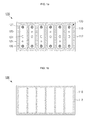
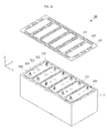
- FIGS. 1a, 1b , 1c and 1d are a plan schematc view, a bottom schematic view, a schematic assembled perspective view and a partially exploded perspective view, respectively, of a battery pack according to one embodiment of the present invention
- FIGS. 2a, 2b and 2c are a schematic plan view, a schematic assembled perspective view and a partially exploded perspective view, respectively, of a battery pack according to another embodiment of the present invention
- FIGS. 3a, 3b and 3c are a schematic plan view, a schematic assembled perspective view and a partially exploded perspective view, respectively, of a battery pack according to another embodiment of the present invention.
- FIGS. 4a, 4b and 4c are a plan view, an assembled perspective view and a partially exploded perspective view, respectively, of a battery pack according to another embodiment of the present invention.
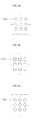
- FIGS. 5a, 5b, 5c , 5d and 5e are schematic plan views illustrating various shapes of cooling passages formed in a battery housing according to embodiments of the present invention.
- FIGS. 6a , 6b and 6c are schematic cross-sectional views illustrating various shapes of cooling passages and an insulating layer formed in a battery housing according to embodiments of the present invention
- FIG. 7 is a schematic plan view illustrating a battery pack according to yet another embodiment of the present invention.
- FIG. 8 is a schematic plan view illustrating a battery pack according to still another embodiment of the present invention.
- FIG. 9 is a schematic plan view illustrating a battery pack according to still another embodiment of the present invention.
- FIGS. 1a through 1d are a schematic plan view, a schematic bottom view, a schematic assembled perspective view and a partially exploded perspective view, respectively, of a battery pack 100 according to one embodiment of the present invention.
- the battery pack 100 includes a battery housing 110 and battery cells 120.
- the battery housing 110 has a plurality of coupling recesses 111 ( FIG. 1d ) formed at a set or predetermined depth and a plurality of cooling passages 112 formed around the circumferences of the coupling recesses 111. That is, the plurality of cooling passages extend in at least one direction of the coupling recesses and within a peripheral portion around the cooling recesses.
- the coupling recesses 111 may be arranged at regular intervals in a horizontal direction of the battery housing 110.
- the coupling recesses 111 have a sufficient depth such that a battery cell 120 can be coupled and stably fixed thereto. There is no restriction on the longitudinal plan or cross-sectional shape of the coupling recesses 111.
- each of the coupling recesses 111 may be rectangular, square or circular when view along a longitudinal cross-section.
- the cooling passages 112 may be arranged at the same pitch or different pitches, i.e. spaced equally from each other or spaced at varying distances from each other, around the circumferences of the coupling recesses 111.
- the coupling recesses 111 may have a depth less than the height of the battery housing 110, while the cooling passages 112 may be formed so as to completely penetrate the battery housing 110 in the vertical direction. This structure allows a cooling gas or fluid to flow freely through the cooling passages 112 from the top to the bottom or vice versa to markedly improve the cooling performance of the battery pack 100.
- the battery housing 110 may be made of a material selected from, but not limited to, aluminum (Al), copper (Cu), iron (Fe), SUS steel, ceramics, polymers and equivalents thereof.
- the ceramics include silicon nitride (Si 3 N 4 ), silicon carbide (SiC), SiAlON, alumina (Al 2 O 3 ) and zirconia (ZrO 2 ), but are not limited thereto.
- the polymers include polypropylene (PP), polyethylene (PE), polybutylene terephthalate (PBT) and perfluoroalkoxy (PFA), but are not limited thereto. Any common technique may be used to form the coupling recesses 111 and the cooling passages 112, and specific examples thereof include, but are not limited to, drawing, extrusion, laser etching and chemical etching.
- Each of the battery cells 120 includes a case 121, an electrode assembly 122, a cap plate 123, a positive terminal 126 and a negative terminal 127.
- the case 121 is coupled to the corresponding coupling recess 111 of the battery housing 110.
- the case 121 may be made of a material selected from aluminum (Al), copper (Cu), iron (Fe), SUS steel, ceramics, polymers and equivalents thereof. However, there is no restriction on the material for the case 121.
- the case 121 may be rectangular, square or circular along a longitudinal plan or cross-section. However, there is no restriction on the longitudinal plan or cross-sectional shape of the case 121.
- the electrode assembly 122 is accommodated together with an electrolyte in the case 121.
- the electrode assembly 122 may be composed of a positive electrode plate, a separator and a negative electrode plate.
- the electrode assembly 122 is produced by rolling the positive electrode plate, the separator and the negative electrode plate about a roll axis several times to form a substantially elliptical or jelly roll shape.
- the cap plate 123 is coupled to the case 121 to cover the electrode assembly 122.
- the coupling of the cap plate 123 to the case 121 may be accomplished by laser welding, resistance welding and/or ultrasonic welding.
- the case 121 and the cap plate 123 may be made of the same or different materials.
- the cap plate 123 may be provided with a safety vent 124 that ruptures to release the internal gas of the case 121 when the internal pressure of the case 121 exceeds an allowable value.
- the thickness of the safety vent 124 may be smaller than that of the cap plate 123.
- a plug 125 may be further coupled to the cap plate 123 to close an injection hole after the electrolyte is injected into the case 121.
- the positive terminal 126 and the negative terminal 127 are coupled to the cap plate 123 and protrude a set or predetermined distance upward from the cap plate 123.
- Each of the positive terminal 126 and the negative terminal 127 may have a threaded outer surface to which a bus bar is fixedly coupled in a subsequent step.
- the positive terminal 126 may be electrically connected to the positive electrode plate of the electrode assembly 122 via a current collector plate, and the negative terminal 127 may be electrically connected to the negative electrode plate of the electrode assembly 122 via a current collector plate 129.
- the positive terminal 126 and the negative terminal 127 may be made of aluminum (Al) and copper (Cu), respectively, but the present invention is not limited to these materials.
- the height of the battery cells 120 may be substantially the same as the depth of the coupling recesses 111 formed in the battery housing 110. With these dimensions, the surface of the cap plate 123 may lie in substantially the same plane as the upper surface of the battery housing 110 when the battery cell 120 is coupled to the corresponding coupling recess 111 of the battery housing 110. It should, of course, be understood that the height of the battery cells 120 may be greater or less than the depth of the coupling recesses 111.
- the cooling passages 112 formed in the battery housing 110 markedly improve the cooling efficiency of the battery pack 110 to reduce or minimize the degradation of the battery pack 110.
- the formation of the cooling passages 112 contributes to an improvement in the strength of the battery housing 110 and a reduction in the weight of the battery housing 110 without additional parts or any increase in thickness. That is, in one embodiment, a honeycomb-like structure of the cooling passages 112 leads to a reduction in the weight of the battery housing 110 while improving the strength of the battery housing 110. Accordingly, the battery cells 120 of the battery pack 100 are properly protected or prevented from swelling.
- FIGS. 2a through 2c are a schematic plan view, a schematic assembled perspective view and a partially exploded perspective view, respectively, of a battery pack 200 according to another embodiment of the present invention.
- the battery pack 200 includes a battery housing 110, battery cells 120 and a heat-screening member 230.
- the battery housing 110 and the battery cells 120 are the same or substantially the same as those described in the previous embodiment.
- the heat-screening member 230 will be primarily explained.
- the heat-screening member 230 is substantially in the form of a thin plate and acts to open or close selected cooling passages 112 formed in the battery housing 110.
- the battery cell 120 positioned corresponding to the center of the battery pack 200 generally has the highest temperature and the battery cells 120 positioned corresponding to both edges of the battery pack 200 generally have the lowest temperatures.
- the heat-screening member 230 is designed such that a relatively large number of the cooling passages 112 in the central region of the battery housing can be opened and a relatively small number of the cooling passages 112 in the edge regions of the battery housing can be closed.
- the heat-screening member 230 has first openings 231 formed in positions of the battery housing 110 corresponding to the battery cells 120 and second openings 232 around the first openings 231 to open the selected cooling passages 112. More specifically, the second openings 232 in positions of the heat-screening member 230 corresponding to the cooling passages 112 in the central region of the battery housing 110 are relatively larger in size and the second openings 232 in positions of the heat-screening member 230 corresponding to the cooling passages 112 in the edge or peripheral regions of the battery housing 110 are relatively smaller in size.
- the heat-screening member 230 may be made of a material selected from, but not limited to, metals, ceramics, polymers and equivalents thereof.
- the heat-screening member 230 may be coupled to the battery housing 110 by adhesion or welding, but not limited thereto and may be coupled by another other suitable coupling method.
- the size and arrangement of the second openings 232 of the heat-screening member 230 in the battery pack 200 can be properly designed to maintain the temperatures of all battery cells 120 stacked in a horizontal direction of the battery housing 110 at substantially the same level during charge or discharge. As a result, the charge and discharge capacities of the battery cells 120 are kept substantially constant, leading to a further improvement in the electrical performance of the battery pack 200.
- FIGS. 3a through 3c are a schematic plan view, a schematic assembled perspective view and a partially exploded perspective view, respectively, of a battery pack 300 according to another embodiment of the present invention.
- the battery pack 300 includes a battery housing 110 and battery cells 320.
- the battery housing 110 is the same or substantially the same as that described in the previous embodiments.
- the battery cells 320 will be primarily explained.
- Each of the battery cells 320 includes an electrode assembly 322, a cap plate 323, a positive terminal 326 and a negative terminal 327.
- the battery housing 110 has coupling recesses 111, each of which accommodates the electrode assembly 322 and an electrolyte therein.
- the electrode assembly 322 may include a positive electrode plate, a separator and a negative electrode plate.
- the positive electrode plate, the separator and the negative electrode plate are rolled about an axis several times.
- the cap plate 323 is directly coupled to the battery housing 110 to cover the electrode assembly 322.
- the coupling of the cap plate 323 to the battery housing 110 may be accomplished by resistance welding, laser welding or ultrasonic welding.
- the cap plate 323 and the battery housing 110 may be made of the same or different materials.
- the cap plate 323 may be provided with a safety vent 324 that ruptures to release the internal gas of the battery cell 320 when the internal pressure of the corresponding coupling recess 111 exceeds the allowable value.
- the thickness of the safety vent 324 may be smaller than that of the cap plate 323.
- a plug 325 may be further coupled to the cap plate 323 to close an injection hole after the electrolyte is injected into the corresponding coupling recess 111.
- the positive terminal 326 and the negative terminal 327 are coupled to the cap plate 323 and protrude a set or predetermined distance upward from the cap plate 323.
- the positive terminal 326 may be electrically connected to the positive electrode plate of the electrode assembly 322 via a current collector plate 328
- the negative terminal 327 may be electrically connected to the negative electrode plate of the electrode assembly 322 via a current collector plate 329.
- the cap plate 323 may have a width larger than a width of a corresponding coupling recess 111 of the battery housing 110 in order for the cap plate 323 to be coupled to the battery housing 110 directly. With these dimensions, the cap plate 323 is formed to a set or predetermined thickness on the upper surface of the battery housing 110. It should be noted that the designs of the coupling recesses 111 and the cap plates 323 may be slightly varied to allow the cap plates 323 to lie in substantially the same plane as the battery housing 110.
- FIGS. 4a through 4c are a schematic plan view, a schematic assembled perspective view and a partially exploded perspective view, respectively, of a battery pack 400 according to another embodiment of the present invention.
- the battery pack 400 includes a battery housing 110, battery cells 320 and a heat-screening member 430.
- the battery housing 110 and the battery cells 320 are the same or substantially the same as those described in the previous embodiment.
- the heat-screening member 430 is also similar to the heat-screening member 230 of the battery pack 200.
- the heat-screening member 430 has first openings 431 formed in positions of the battery housing 110 corresponding to the battery cells 320 and second openings 432 formed around the first openings 431 to open selected cooling passages 112 of the battery housing 110.
- the second openings 432 in positions of the heat-screening member 430 corresponding to the cooling passages 112 in the central region of the battery housing 110 are relatively larger in size and the second openings 432 of the heat-screening member 430 in positions corresponding to the cooling passages 112 in the edge regions of the battery housing 110 are relatively smaller in size.
- the heat screening member 430 has a substantially planar surface covering a first array of the plurality of cooling passages, a first opening exposing the at least one coupling recess, and a plurality of second openings each exposing a second array of the plurality of cooling passages.
- the peripheral portion comprises a first peripheral portion and a second peripheral portion, wherein the heat screening member 430 exposes a larger number of the plurality of cooling passages in the first peripheral portion than in the second peripheral portion.
- the cap plates 323 of the battery cells 320 protrude from the surface of the battery housing 110.
- the cap plates 323 may lie in substantially the same plane as the heat-screening member 430 when the thickness of the cap plates 323 is substantially equal to a thickness of the heat-screening member 430. That is, the cap plates 323 may be flush with the heat-screening member 430.
- the temperatures of all battery cells 320 stacked in a horizontal direction of the battery housing 110 can be maintained at substantially the same level during charge or discharge.
- the charge and discharge capacities of the battery cells 320 are kept relatively constant, leading to an improvement in the electrical performance of the battery pack 400.
- FIGS. 5a through 5e are schematic plan views illustrating various shapes of cooling passages formed in a battery housing according to embodiments of the present invention.
- FIG. 5a illustrates cooling passages 112a having a substantially circular longitudinal cross-sectional shape
- FIG. 5b illustrates cooling passages 112b having a substantially quadrangular longitudinal cross-sectional shape
- FIG. 5c illustrates cooling passages 112c having a substantially lozenge or diamond longitudinal cross-sectional shape
- FIG. 5d illustrates cooling passages 112d having a substantially pentagonal longitudinal cross-sectional shape
- FIG. 5e illustrates cooling passages 112e having a substantially hexagonal longitudinal cross-sectional shape.
- the shapes of the cooling passages are merely illustrative and the present invention is not limited thereto.
- FIGS. 6a , 6b and 6c are schematic cross-sectional views illustrating various shapes of cooling passages and an insulating layer formed in a battery housing 610a according to embodiments of the present invention.
- the arrows indicate the flow directions of the cooling medium.
- the battery housing 610a has a coupling recess 611 a of a set or predetermined depth and a plurality of cooling passages 612a formed around the circumference of the coupling recess 611a.
- the cooling passages 612a are formed so as to penetrate the battery housing 610a. That is, each of the cooling passages 612a has open upper and lower ends.
- the battery housing 610a may include an insulating layer 616a of a set or predetermined thickness on the outer perimeter or circumstantial surface thereof to define the coupling recess 611 a.
- the insulating layer 616a has a sufficiently low electrical conductivity and is highly resistant to chemicals. The electrical and chemical properties of the insulating layer 616a permit direct accommodation of an electrolyte in the coupling recess 611 a of the battery housing 610a. Further, even when a battery cell 320 is coupled to the coupling recess 611 a directly, the insulating layer 616a can prevent or protect from unnecessary electrical shorting between the coupling recess 611 a of the battery housing 610a and the battery cell 320.
- the insulating layer 616a may be an anodizing layer.
- the anodizing layer refers to an aluminum oxide film that is formed on the aluminum surface by oxygen produced from the aluminum material acting as a positive electrode in the electrolyte.
- the aluminum oxide film has an extremely low electrical conductivity and is highly resistant to chemicals.
- Non-limiting examples of the insulating layer 616a are polyethylene terephthalate (PET) or ethylene propylene diene M-class (EPDM) coatings.
- a plurality of cooling passages 612b may be formed so as to penetrate the battery housing 610b. That is, each of the cooling passages 612b has open upper and lower ends. Due to the structure, a cooling medium may flow upwardly or downwardly along the cooling passages 612b. Additionally, the battery housing 610b may include an outer insulation layer 616b.
- the battery housing 610c may have cooling passages 612c, each of which has one closed end.
- the upper ends of the cooling passages 612c may be closed and the lower ends thereof may be opened.
- the two adjacent cooling passages 612c may be connected to each other in the upper region thereof to form a substantially "U" shape as a whole. With this configuration, a cooling medium flows along the cooling passages 612c in a "U" shape to cool the battery housing 610c.
- the battery housing 610c may include an outer insulation layer 616c.
- cooling passages 612c may be formed in the horizontal direction instead of the vertical direction or may be formed in both horizontal and vertical directions. There is no restriction on the direction and shape of the cooling passages 112.
- FIGS. 7 and 8 are schematic plan views illustrating battery packs 500 and 600, respectively, according to embodiments of the present invention.
- the battery pack 500 of FIG. 7 is structurally similar to the battery pack 100 of FIGS. 1a through 1d .
- the battery pack 600 of FIG. 8 is structurally similar to the battery pack 300 of FIGS. 3a through 3c . Differences between the battery packs will be explained hereinafter.
- the battery packs 500 and 600 include battery housings 510 and 610 having cooling passages 512 and 612, respectively.
- the cooling passages 512 and 612 are grouped at a first pitch.
- each of the groups 513 and 613 is composed of four cooling passages 512 and 612, there is no restriction on the number of the cooling passages 512 and 612 necessary to form each of the groups 513 and 613.
- the groups 513 and 613 themselves may be arranged at a second pitch greater than the first pitch. Such an arrangement allows for the formation of relatively wide regions 514 or 614 between the adjacent groups 513 and 613.
- the wide regions 514 or 614 are formed as reinforcing regions between the groups 513 and 613 of the cooling passages 512 and 612 to further stiffen the battery housing 510 or 610.
- the strength of the battery housing 510 and 610 of the battery pack 500 or 600 can be further improved without any additional parts or any increase in the thickness of the battery housing 510 and 610 to efficiently prevent battery cells 120 or 320 from swelling arising from an increase in internal pressure during charging or discharging of the battery pack 500 or 600.
- FIG. 9 is a schematic plan view illustrating a battery pack according to still another embodiment of the present invention.
- the battery packs 700 includes a battery housing 110 and battery cells 120 or 320.
- the battery cells 120 or 320 are the same or substantially the same as those described in the previous embodiment.
- the battery housing 110 will be primarily explained.
- the number of cooling passages 112 is different between the central region and peripheral region of the battery housing 110.
- the number of cooling passages 112 is relatively large at the central region of the battery housing 110 while the number of cooling passages 112 is relatively small at the peripheral region of the battery housing 110.
- the number of cooling passages 112 in the central region between adjacent coupling recesses 111 is larger than the number of cooling passages 112 in the peripheral region of the batter housing 110.
- the pitch of cooling passages 112 is relatively smaller at the central region of the battery housing 110 while the pitch of cooling passages 112 is relatively larger at the peripheral region of the battery housing 110.
- the temperatures of all battery cells 120 or 320 stacked in a horizontal direction of the battery housing 110 can be maintained at substantially the same level during charge or discharge.
- the charge and discharge capacities of the battery cells 120 or 320 are kept relatively constant, leading to an improvement in the electrical performance of the battery pack 700.
- a plurality of cooling passages formed in the battery housing of an embodiment of the present invention can improve the strength of the battery housing even without any additional parts or any increase in thickness to prevent battery cells from swelling arising from an increase in internal pressure during charging/discharging of the battery pack.
- a plurality of cooling passages formed in the battery housing improves the cooling efficiency of the battery pack even without the necessity for any additional cooling members, so that heat generated during charging or discharging of the battery pack can be released rapidly outside to reduce or minimize the degradation of the battery pack.
- a heat-screening member capable of selectively opening or closing a plurality of cooling passages formed in the battery housing is disposed on the battery housing to control the cooling efficiencies of different regions of the battery pack, so that the temperatures of all battery cells in the battery pack can be maintained at substantially the same level, achieving optimum battery performance.
Landscapes
- Chemical & Material Sciences (AREA)
- Chemical Kinetics & Catalysis (AREA)
- Electrochemistry (AREA)
- General Chemical & Material Sciences (AREA)
- Engineering & Computer Science (AREA)
- Manufacturing & Machinery (AREA)
- Inorganic Chemistry (AREA)
- Battery Mounting, Suspending (AREA)
- Secondary Cells (AREA)
- Sealing Battery Cases Or Jackets (AREA)
Abstract
Description
- Aspects of the present invention relate to a battery housing for a battery pack and a battery pack including the housing.
- Generally, a battery pack is mounted as a power supply system on a hybrid vehicle or an electric vehicle that can be driven by the interaction of an engine with an electric motor.
- It is an object of the present invention to provide a battery back having a housing with improved cooling that has sufficient strength to prevent swelling of the battery without providing any additional part or any increase in thickness.
- An embodiment of the present invention provides a battery pack comprising a housing having at least one coupling recess, at least one battery cell accommodated in the at least one coupling recess of the housing, wherein a plurality of cooling passages are provided around the circumference of the at least one coupling recess and extend along at least one direction of the at least one coupling recess.
- The provision of the cooling passages along the circumference of the coupling recesses improves the cooling efficiency of a battery pack while minimizing the degradation of the battery pack. The cooling efficiency of the different regions of the battery pack is improved and the temperature of all battery cells with the battery pack can be maintained, achieving optimum battery performance.
- The cooling passages may be provided with an end formed on the same side of the housing in which the at least one coupling recesses is provided.
- Each cooling passage may comprise two ends formed on opposing surfaces of the housing.
- Each cooling passage may comprise one open end formed on the surface of the housing and one closed end formed within the housing and/or two adjacent cooling passages may be connected to each other in the regions of their closed ends.
- A plurality of cooling passages may be provided, the individual cooling passages being separated from another.
- The plurality of cooling passages may be arranged at the same pitch on the surface of the housing, or the pitch of the plurality of cooling passages arranged in a central region of the battery housing between adjacent coupling recesses may be smaller than the pitch of the plurality of cooling passages at a peripheral region of the battery housing, or the number of cooling passages in a central region of the battery housing between adjacent coupling recesses may be larger than the number of cooling passages at a peripheral region of the battery housing.
- Groups of cooling passages may be provided, the cooling passages within a group being arranged with a first pitch, the groups of cooling passages being arranged with a second pitch different and/or greater than the first pitch.
- The battery pack may further comprise a heat-screening member coupled to the housing to selectively open or close cooling passages. The heat-screening member may comprise first openings formed in locations corresponding to locations of the at least one coupling recess, and second openings formed at locations corresponding to locations of the circumference of the at least one coupling recess.
- Second openings of the heat-screening member formed at central regions of the housing may have a larger cross-section than second openings formed at peripheral regions of the housing.
- The battery cell may comprise an electrode assembly; a cap plate covering the electrode assembly; a positive terminal coupled to the cap plate; and a negative terminal coupled to the cap plate.
- A case may further be provided being coupled to the corresponding coupling recess, the electrode assembly being accommodated in the case and the cap plate being coupled to the case.
- The cap plate may be coupled to the housing.
- The cap plate may be arranged below said heat-screening member or wherein the cap plate protrudes from the surface of the housing such that the cap plate and the heat-screening member lie essentially in the same plane.
- The housing may comprise an insulating layer on its inner surfaces defining the at least one coupling recess. Also, the housing may comprise at least one selected from the group of aluminum (AI), copper (Cu), iron (Fe), SUS, ceramics, and polymers.
- Additional aspects of the invention will be set forth in part in the description which follows.
- These and/or other aspects and advantages of the invention will become apparent and more readily appreciated from the following description of the embodiments, taken in conjunction with the accompanying drawings of which:
-
FIGS. 1a, 1b ,1c and1d are a plan schematc view, a bottom schematic view, a schematic assembled perspective view and a partially exploded perspective view, respectively, of a battery pack according to one embodiment of the present invention; -
FIGS. 2a, 2b and2c are a schematic plan view, a schematic assembled perspective view and a partially exploded perspective view, respectively, of a battery pack according to another embodiment of the present invention; -
FIGS. 3a, 3b and3c are a schematic plan view, a schematic assembled perspective view and a partially exploded perspective view, respectively, of a battery pack according to another embodiment of the present invention; -
FIGS. 4a, 4b and4c are a plan view, an assembled perspective view and a partially exploded perspective view, respectively, of a battery pack according to another embodiment of the present invention; -
FIGS. 5a, 5b, 5c ,5d and 5e are schematic plan views illustrating various shapes of cooling passages formed in a battery housing according to embodiments of the present invention; -
FIGS. 6a ,6b and 6c are schematic cross-sectional views illustrating various shapes of cooling passages and an insulating layer formed in a battery housing according to embodiments of the present invention; -
FIG. 7 is a schematic plan view illustrating a battery pack according to yet another embodiment of the present invention; -
FIG. 8 is a schematic plan view illustrating a battery pack according to still another embodiment of the present invention; and -
FIG. 9 is a schematic plan view illustrating a battery pack according to still another embodiment of the present invention. - Reference will now be made in detail to the embodiments of the present invention, examples of which are illustrated in the accompanying drawings, wherein like reference numerals refer to the like elements throughout. The embodiments are described below in order to explain the present invention by referring to the figures.
-
FIGS. 1a through 1d are a schematic plan view, a schematic bottom view, a schematic assembled perspective view and a partially exploded perspective view, respectively, of abattery pack 100 according to one embodiment of the present invention. - As illustrated in
FIGS. 1a through 1d , thebattery pack 100 includes abattery housing 110 andbattery cells 120. - The
battery housing 110 has a plurality of coupling recesses 111 (FIG. 1d ) formed at a set or predetermined depth and a plurality ofcooling passages 112 formed around the circumferences of thecoupling recesses 111. That is, the plurality of cooling passages extend in at least one direction of the coupling recesses and within a peripheral portion around the cooling recesses. Thecoupling recesses 111 may be arranged at regular intervals in a horizontal direction of thebattery housing 110. Thecoupling recesses 111 have a sufficient depth such that abattery cell 120 can be coupled and stably fixed thereto. There is no restriction on the longitudinal plan or cross-sectional shape of thecoupling recesses 111. For example, each of thecoupling recesses 111 may be rectangular, square or circular when view along a longitudinal cross-section. Thecooling passages 112 may be arranged at the same pitch or different pitches, i.e. spaced equally from each other or spaced at varying distances from each other, around the circumferences of thecoupling recesses 111. Thecoupling recesses 111 may have a depth less than the height of thebattery housing 110, while thecooling passages 112 may be formed so as to completely penetrate thebattery housing 110 in the vertical direction. This structure allows a cooling gas or fluid to flow freely through thecooling passages 112 from the top to the bottom or vice versa to markedly improve the cooling performance of thebattery pack 100. - The
battery housing 110 may be made of a material selected from, but not limited to, aluminum (Al), copper (Cu), iron (Fe), SUS steel, ceramics, polymers and equivalents thereof. Examples of the ceramics include silicon nitride (Si3N4), silicon carbide (SiC), SiAlON, alumina (Al2O3) and zirconia (ZrO2), but are not limited thereto. Examples of the polymers include polypropylene (PP), polyethylene (PE), polybutylene terephthalate (PBT) and perfluoroalkoxy (PFA), but are not limited thereto. Any common technique may be used to form thecoupling recesses 111 and thecooling passages 112, and specific examples thereof include, but are not limited to, drawing, extrusion, laser etching and chemical etching. - Each of the
battery cells 120 includes acase 121, anelectrode assembly 122, acap plate 123, apositive terminal 126 and anegative terminal 127. - The
case 121 is coupled to the correspondingcoupling recess 111 of thebattery housing 110. Thecase 121 may be made of a material selected from aluminum (Al), copper (Cu), iron (Fe), SUS steel, ceramics, polymers and equivalents thereof. However, there is no restriction on the material for thecase 121. Thecase 121 may be rectangular, square or circular along a longitudinal plan or cross-section. However, there is no restriction on the longitudinal plan or cross-sectional shape of thecase 121. - The
electrode assembly 122 is accommodated together with an electrolyte in thecase 121. Theelectrode assembly 122 may be composed of a positive electrode plate, a separator and a negative electrode plate. In one embodiment, theelectrode assembly 122 is produced by rolling the positive electrode plate, the separator and the negative electrode plate about a roll axis several times to form a substantially elliptical or jelly roll shape. - The
cap plate 123 is coupled to thecase 121 to cover theelectrode assembly 122. The coupling of thecap plate 123 to thecase 121 may be accomplished by laser welding, resistance welding and/or ultrasonic welding. Thecase 121 and thecap plate 123 may be made of the same or different materials. Thecap plate 123 may be provided with asafety vent 124 that ruptures to release the internal gas of thecase 121 when the internal pressure of thecase 121 exceeds an allowable value. The thickness of thesafety vent 124 may be smaller than that of thecap plate 123. Aplug 125 may be further coupled to thecap plate 123 to close an injection hole after the electrolyte is injected into thecase 121. - The
positive terminal 126 and thenegative terminal 127 are coupled to thecap plate 123 and protrude a set or predetermined distance upward from thecap plate 123. Each of thepositive terminal 126 and thenegative terminal 127 may have a threaded outer surface to which a bus bar is fixedly coupled in a subsequent step. Thepositive terminal 126 may be electrically connected to the positive electrode plate of theelectrode assembly 122 via a current collector plate, and thenegative terminal 127 may be electrically connected to the negative electrode plate of theelectrode assembly 122 via acurrent collector plate 129. Thepositive terminal 126 and thenegative terminal 127 may be made of aluminum (Al) and copper (Cu), respectively, but the present invention is not limited to these materials. - The height of the
battery cells 120, each of which includes thecase 121 and thecap plate 123, may be substantially the same as the depth of the coupling recesses 111 formed in thebattery housing 110. With these dimensions, the surface of thecap plate 123 may lie in substantially the same plane as the upper surface of thebattery housing 110 when thebattery cell 120 is coupled to the correspondingcoupling recess 111 of thebattery housing 110. It should, of course, be understood that the height of thebattery cells 120 may be greater or less than the depth of the coupling recesses 111. - In this embodiment, the
cooling passages 112 formed in thebattery housing 110 markedly improve the cooling efficiency of thebattery pack 110 to reduce or minimize the degradation of thebattery pack 110. In addition, the formation of thecooling passages 112 contributes to an improvement in the strength of thebattery housing 110 and a reduction in the weight of thebattery housing 110 without additional parts or any increase in thickness. That is, in one embodiment, a honeycomb-like structure of thecooling passages 112 leads to a reduction in the weight of thebattery housing 110 while improving the strength of thebattery housing 110. Accordingly, thebattery cells 120 of thebattery pack 100 are properly protected or prevented from swelling. -
FIGS. 2a through 2c are a schematic plan view, a schematic assembled perspective view and a partially exploded perspective view, respectively, of abattery pack 200 according to another embodiment of the present invention. - As illustrated in
FIGS. 2a through 2c , thebattery pack 200 includes abattery housing 110,battery cells 120 and a heat-screening member 230. Thebattery housing 110 and thebattery cells 120 are the same or substantially the same as those described in the previous embodiment. Hereinafter, the heat-screening member 230 will be primarily explained. - The heat-
screening member 230 is substantially in the form of a thin plate and acts to open or close selected coolingpassages 112 formed in thebattery housing 110. During charging or discharging of thebattery pack 200, thebattery cell 120 positioned corresponding to the center of thebattery pack 200 generally has the highest temperature and thebattery cells 120 positioned corresponding to both edges of thebattery pack 200 generally have the lowest temperatures. Thus, the heat-screening member 230 is designed such that a relatively large number of thecooling passages 112 in the central region of the battery housing can be opened and a relatively small number of thecooling passages 112 in the edge regions of the battery housing can be closed. - In one embodiment, the heat-
screening member 230 hasfirst openings 231 formed in positions of thebattery housing 110 corresponding to thebattery cells 120 andsecond openings 232 around thefirst openings 231 to open the selectedcooling passages 112. More specifically, thesecond openings 232 in positions of the heat-screening member 230 corresponding to thecooling passages 112 in the central region of thebattery housing 110 are relatively larger in size and thesecond openings 232 in positions of the heat-screening member 230 corresponding to thecooling passages 112 in the edge or peripheral regions of thebattery housing 110 are relatively smaller in size. - The heat-
screening member 230 may be made of a material selected from, but not limited to, metals, ceramics, polymers and equivalents thereof. The heat-screening member 230 may be coupled to thebattery housing 110 by adhesion or welding, but not limited thereto and may be coupled by another other suitable coupling method. - In this embodiment, the size and arrangement of the
second openings 232 of the heat-screening member 230 in thebattery pack 200 can be properly designed to maintain the temperatures of allbattery cells 120 stacked in a horizontal direction of thebattery housing 110 at substantially the same level during charge or discharge. As a result, the charge and discharge capacities of thebattery cells 120 are kept substantially constant, leading to a further improvement in the electrical performance of thebattery pack 200. -
FIGS. 3a through 3c are a schematic plan view, a schematic assembled perspective view and a partially exploded perspective view, respectively, of abattery pack 300 according to another embodiment of the present invention. - As illustrated in
FIGS. 3a through 3c , thebattery pack 300 includes abattery housing 110 andbattery cells 320. Thebattery housing 110 is the same or substantially the same as that described in the previous embodiments. Hereinafter, thebattery cells 320 will be primarily explained. - Each of the
battery cells 320 includes anelectrode assembly 322, acap plate 323, apositive terminal 326 and anegative terminal 327. - The
battery housing 110 has coupling recesses 111, each of which accommodates theelectrode assembly 322 and an electrolyte therein. Theelectrode assembly 322 may include a positive electrode plate, a separator and a negative electrode plate. The positive electrode plate, the separator and the negative electrode plate are rolled about an axis several times. - The
cap plate 323 is directly coupled to thebattery housing 110 to cover theelectrode assembly 322. The coupling of thecap plate 323 to thebattery housing 110 may be accomplished by resistance welding, laser welding or ultrasonic welding. Thecap plate 323 and thebattery housing 110 may be made of the same or different materials. Thecap plate 323 may be provided with asafety vent 324 that ruptures to release the internal gas of thebattery cell 320 when the internal pressure of the correspondingcoupling recess 111 exceeds the allowable value. The thickness of thesafety vent 324 may be smaller than that of thecap plate 323. Aplug 325 may be further coupled to thecap plate 323 to close an injection hole after the electrolyte is injected into the correspondingcoupling recess 111. - The
positive terminal 326 and thenegative terminal 327 are coupled to thecap plate 323 and protrude a set or predetermined distance upward from thecap plate 323. Thepositive terminal 326 may be electrically connected to the positive electrode plate of theelectrode assembly 322 via acurrent collector plate 328, and thenegative terminal 327 may be electrically connected to the negative electrode plate of theelectrode assembly 322 via acurrent collector plate 329. - The
cap plate 323 may have a width larger than a width of acorresponding coupling recess 111 of thebattery housing 110 in order for thecap plate 323 to be coupled to thebattery housing 110 directly. With these dimensions, thecap plate 323 is formed to a set or predetermined thickness on the upper surface of thebattery housing 110. It should be noted that the designs of the coupling recesses 111 and thecap plates 323 may be slightly varied to allow thecap plates 323 to lie in substantially the same plane as thebattery housing 110. - In this embodiment, no case is used in each of the
battery cells 320, contributing to a reduction in the manufacturing cost of thefinal battery pack 300. As described above, the use of a plurality of coolingpassages 112 in thebattery housing 110 contributes to improvements in the cooling performance and strength of thebattery housing 110, thus eventually preventing or protecting from deterioration of thebattery cells 320 while inhibiting swelling of thebattery cells 320. -
FIGS. 4a through 4c are a schematic plan view, a schematic assembled perspective view and a partially exploded perspective view, respectively, of abattery pack 400 according to another embodiment of the present invention. - As illustrated in
FIGS. 4a through 4c , thebattery pack 400 includes abattery housing 110,battery cells 320 and a heat-screening member 430. Thebattery housing 110 and thebattery cells 320 are the same or substantially the same as those described in the previous embodiment. Actually, the heat-screening member 430 is also similar to the heat-screening member 230 of thebattery pack 200. - The heat-
screening member 430 hasfirst openings 431 formed in positions of thebattery housing 110 corresponding to thebattery cells 320 andsecond openings 432 formed around thefirst openings 431 to open selected coolingpassages 112 of thebattery housing 110. Thesecond openings 432 in positions of the heat-screening member 430 corresponding to thecooling passages 112 in the central region of thebattery housing 110 are relatively larger in size and thesecond openings 432 of the heat-screening member 430 in positions corresponding to thecooling passages 112 in the edge regions of thebattery housing 110 are relatively smaller in size. That is, theheat screening member 430 has a substantially planar surface covering a first array of the plurality of cooling passages, a first opening exposing the at least one coupling recess, and a plurality of second openings each exposing a second array of the plurality of cooling passages. In one embodiment, as shown inFIG. 4a , the peripheral portion comprises a first peripheral portion and a second peripheral portion, wherein theheat screening member 430 exposes a larger number of the plurality of cooling passages in the first peripheral portion than in the second peripheral portion. - The
cap plates 323 of thebattery cells 320 protrude from the surface of thebattery housing 110. Thecap plates 323 may lie in substantially the same plane as the heat-screening member 430 when the thickness of thecap plates 323 is substantially equal to a thickness of the heat-screening member 430. That is, thecap plates 323 may be flush with the heat-screening member 430. - In this embodiment, the temperatures of all
battery cells 320 stacked in a horizontal direction of thebattery housing 110 can be maintained at substantially the same level during charge or discharge. As a result, the charge and discharge capacities of thebattery cells 320 are kept relatively constant, leading to an improvement in the electrical performance of thebattery pack 400. -
FIGS. 5a through 5e are schematic plan views illustrating various shapes of cooling passages formed in a battery housing according to embodiments of the present invention. -
FIG. 5a illustrates coolingpassages 112a having a substantially circular longitudinal cross-sectional shape,FIG. 5b illustrates coolingpassages 112b having a substantially quadrangular longitudinal cross-sectional shape,FIG. 5c illustrates coolingpassages 112c having a substantially lozenge or diamond longitudinal cross-sectional shape,FIG. 5d illustrates coolingpassages 112d having a substantially pentagonal longitudinal cross-sectional shape, andFIG. 5e illustrates coolingpassages 112e having a substantially hexagonal longitudinal cross-sectional shape. The shapes of the cooling passages are merely illustrative and the present invention is not limited thereto. -
FIGS. 6a ,6b and 6c are schematic cross-sectional views illustrating various shapes of cooling passages and an insulating layer formed in abattery housing 610a according to embodiments of the present invention. InFIGS. 6a through 6c , the arrows indicate the flow directions of the cooling medium. - As illustrated in
FIG. 6a , thebattery housing 610a has acoupling recess 611 a of a set or predetermined depth and a plurality ofcooling passages 612a formed around the circumference of thecoupling recess 611a. Thecooling passages 612a are formed so as to penetrate thebattery housing 610a. That is, each of thecooling passages 612a has open upper and lower ends. - The
battery housing 610a may include an insulatinglayer 616a of a set or predetermined thickness on the outer perimeter or circumstantial surface thereof to define thecoupling recess 611 a. In one embodiment, the insulatinglayer 616a has a sufficiently low electrical conductivity and is highly resistant to chemicals. The electrical and chemical properties of the insulatinglayer 616a permit direct accommodation of an electrolyte in thecoupling recess 611 a of thebattery housing 610a. Further, even when abattery cell 320 is coupled to thecoupling recess 611 a directly, the insulatinglayer 616a can prevent or protect from unnecessary electrical shorting between thecoupling recess 611 a of thebattery housing 610a and thebattery cell 320. - When the
battery housing 610a is made of aluminum, the insulatinglayer 616a may be an anodizing layer. As commonly known in the art, the anodizing layer refers to an aluminum oxide film that is formed on the aluminum surface by oxygen produced from the aluminum material acting as a positive electrode in the electrolyte. The aluminum oxide film has an extremely low electrical conductivity and is highly resistant to chemicals. Non-limiting examples of the insulatinglayer 616a are polyethylene terephthalate (PET) or ethylene propylene diene M-class (EPDM) coatings. - As illustrated in
FIG. 6b , a plurality of coolingpassages 612b may be formed so as to penetrate thebattery housing 610b. That is, each of thecooling passages 612b has open upper and lower ends. Due to the structure, a cooling medium may flow upwardly or downwardly along thecooling passages 612b. Additionally, thebattery housing 610b may include anouter insulation layer 616b. - As illustrated in
FIG. 6c , thebattery housing 610c may havecooling passages 612c, each of which has one closed end. For example, the upper ends of thecooling passages 612c may be closed and the lower ends thereof may be opened. The twoadjacent cooling passages 612c may be connected to each other in the upper region thereof to form a substantially "U" shape as a whole. With this configuration, a cooling medium flows along thecooling passages 612c in a "U" shape to cool thebattery housing 610c. Additionally, thebattery housing 610c may include anouter insulation layer 616c. - Alternatively, the
cooling passages 612c may be formed in the horizontal direction instead of the vertical direction or may be formed in both horizontal and vertical directions. There is no restriction on the direction and shape of thecooling passages 112. -
FIGS. 7 and 8 are schematic plan views illustrating battery packs 500 and 600, respectively, according to embodiments of the present invention. Thebattery pack 500 ofFIG. 7 is structurally similar to thebattery pack 100 ofFIGS. 1a through 1d . The battery pack 600 ofFIG. 8 is structurally similar to thebattery pack 300 ofFIGS. 3a through 3c . Differences between the battery packs will be explained hereinafter. - As illustrated in
FIGS. 7 and 8 , the battery packs 500 and 600 includebattery housings cooling passages cooling passages groups cooling passages cooling passages groups groups wide regions adjacent groups wide regions groups cooling passages battery housing - Therefore, the strength of the
battery housing battery pack 500 or 600 can be further improved without any additional parts or any increase in the thickness of thebattery housing battery cells battery pack 500 or 600. -
FIG. 9 is a schematic plan view illustrating a battery pack according to still another embodiment of the present invention. - As illustrated in
FIG. 9 , the battery packs 700 includes abattery housing 110 andbattery cells battery cells battery housing 110 will be primarily explained. - In this embodiment, the number of
cooling passages 112 is different between the central region and peripheral region of thebattery housing 110. For example, the number ofcooling passages 112 is relatively large at the central region of thebattery housing 110 while the number ofcooling passages 112 is relatively small at the peripheral region of thebattery housing 110. In other words, the number ofcooling passages 112 in the central region between adjacent coupling recesses 111 is larger than the number ofcooling passages 112 in the peripheral region of thebatter housing 110. In another example, the pitch of coolingpassages 112 is relatively smaller at the central region of thebattery housing 110 while the pitch of coolingpassages 112 is relatively larger at the peripheral region of thebattery housing 110. - In this embodiment, the temperatures of all
battery cells battery housing 110 can be maintained at substantially the same level during charge or discharge. As a result, the charge and discharge capacities of thebattery cells battery pack 700. - As is apparent from the above description, a plurality of cooling passages formed in the battery housing of an embodiment of the present invention can improve the strength of the battery housing even without any additional parts or any increase in thickness to prevent battery cells from swelling arising from an increase in internal pressure during charging/discharging of the battery pack.
- In addition, a plurality of cooling passages formed in the battery housing improves the cooling efficiency of the battery pack even without the necessity for any additional cooling members, so that heat generated during charging or discharging of the battery pack can be released rapidly outside to reduce or minimize the degradation of the battery pack.
- Furthermore, a heat-screening member capable of selectively opening or closing a plurality of cooling passages formed in the battery housing is disposed on the battery housing to control the cooling efficiencies of different regions of the battery pack, so that the temperatures of all battery cells in the battery pack can be maintained at substantially the same level, achieving optimum battery performance.
- While the present invention has been described in connection with certain exemplary embodiments, it is to be understood that the invention is not limited to the disclosed embodiments, but, on the contrary, is intended to cover various modifications and equivalent arrangements included within the scope of the appended claims, and equivalents thereof.
Claims (15)
- A battery pack comprising:a housing having at least one coupling recess;at least one battery cell accommodated in the at least one coupling recess of the housing;
characterized in thata plurality of cooling passages are provided around the circumference of the at least one coupling recess and extend along at least one direction of the at least one coupling recess. - The battery pack of claim 1, wherein the cooling passages are provided with an end formed on the same side of the housing in which the at least one coupling recesses is provided.
- The battery pack of claim 1 or 2, wherein each cooling passage comprises two ends formed on opposing surfaces of the housing.
- The battery pack of claim 1 or 2, wherein each cooling passage comprises one open end formed on the surface of the housing and one closed end formed within the housing and/or wherein two adjacent cooling passages are connected to each other in the regions of their closed ends.
- The battery pack of one of the previous claims, wherein a plurality of cooling passages is provided, the individual cooling passages being separated from another.
- The battery pack of one of the previous claims, wherein
the plurality of cooling passages are arranged at the same pitch on the surface of the housing, or
the pitch of the plurality of cooling passages arranged in a central region of the battery housing between adjacent coupling recesses is smaller than the pitch of the plurality of cooling passages at a peripheral region of the battery housing, or
the number of cooling passages in a central region of the battery housing between adjacent coupling recesses is larger than the number of cooling passages at a peripheral region of the battery housing. - The battery pack of one of the previous claims 1 to 5, wherein groups of cooling passages are provided, the cooling passages within a group being arranged with a first pitch, the groups of cooling passages being arranged with a second pitch different and/or greater than the first pitch.
- The battery pack of one of the previous claims, further comprising a heat-screening member coupled to the housing to selectively open or close cooling passages, the heat-screening member comprising:first openings formed in locations corresponding to locations of the at least one coupling recess, andsecond openings formed at locations corresponding to locations of the circumference of the at least one coupling recess.
- The battery pack of claim 8, wherein second openings of the heat-screening member formed at central regions of the housing have a larger cross-section than second openings formed at peripheral regions of the housing.
- The battery pack of one of the previous claims, wherein the battery cell comprises:an electrode assembly;a cap plate covering the electrode assembly;a positive terminal coupled to the cap plate; anda negative terminal coupled to the cap plate.
- The battery pack of claim 10, wherein a case is further provided being coupled to the corresponding coupling recess, the electrode assembly being accommodated in the case and the cap plate being coupled to the case.
- The battery pack of claim 10, wherein the cap plate is coupled to the housing.
- The battery pack of claim 10, wherein the cap plate is arranged below said heat-screening member or wherein the cap plate protrudes from the surface of the housing such that the cap plate and the heat-screening member lie essentially in the same plane.
- The battery pack of one of the previous claims, wherein the housing comprises an insulating layer on its inner surfaces defining the at least one coupling recess.
- The battery pack of one of the previous claims, wherein the housing comprises at least one selected from the group of aluminum (Al), copper (Cu), iron (Fe), SUS, ceramics, and polymers.
Applications Claiming Priority (2)
| Application Number | Priority Date | Filing Date | Title |
|---|---|---|---|
| US15542209P | 2009-02-25 | 2009-02-25 | |
| US12/496,607 US8216713B2 (en) | 2009-02-25 | 2009-07-01 | Battery housing formed with cooling passages and battery pack having the same |
Publications (2)
| Publication Number | Publication Date |
|---|---|
| EP2228851A1 true EP2228851A1 (en) | 2010-09-15 |
| EP2228851B1 EP2228851B1 (en) | 2013-04-03 |
Family
ID=41402625
Family Applications (1)
| Application Number | Title | Priority Date | Filing Date |
|---|---|---|---|
| EP20090171611 Active EP2228851B1 (en) | 2009-02-25 | 2009-09-29 | Battery housing formed with cooling passages and battery pack having the same |
Country Status (5)
| Country | Link |
|---|---|
| US (1) | US8216713B2 (en) |
| EP (1) | EP2228851B1 (en) |
| JP (1) | JP5204141B2 (en) |
| KR (1) | KR101106356B1 (en) |
| CN (1) | CN101814620B (en) |
Cited By (7)
| Publication number | Priority date | Publication date | Assignee | Title |
|---|---|---|---|---|
| WO2012013582A1 (en) * | 2010-07-30 | 2012-02-02 | Valeo Klimasysteme Gmbh | Cooling device for a vehicle battery and a vehicle battery with such a cooling device |
| WO2014014623A1 (en) * | 2012-07-18 | 2014-01-23 | General Electric Company | Energy storage device and method |
| EP3079183A4 (en) * | 2014-04-03 | 2017-08-30 | LG Chem, Ltd. | Battery module array comprising under-base bar |
| WO2017178634A1 (en) * | 2016-04-14 | 2017-10-19 | Saft | Assembly of electrochemical elements using an additive manufacturing method |
| FR3071961A1 (en) * | 2017-10-04 | 2019-04-05 | Valeo Systemes Thermiques | BOX FOR PROTECTING A BATTERY PACK INTEGRATING TRANSPORT CHANNELS FROM A HEAT TRANSFER FLUID |
| CN112635889A (en) * | 2020-12-10 | 2021-04-09 | 东风汽车集团有限公司 | Explosion-proof battery |
| EP4012822A1 (en) * | 2020-12-09 | 2022-06-15 | Huawei Digital Power Technologies Co., Ltd. | Battery module, battery pack, and vehicle |
Families Citing this family (70)
| Publication number | Priority date | Publication date | Assignee | Title |
|---|---|---|---|---|
| JP5514578B2 (en) * | 2009-02-24 | 2014-06-04 | 矢崎総業株式会社 | Battery pack cooling structure |
| KR101050315B1 (en) * | 2009-02-26 | 2011-07-19 | 에스비리모티브 주식회사 | Secondary battery module |
| US9905821B2 (en) * | 2010-11-15 | 2018-02-27 | Volkswagen Ag | Vehicle battery packaging |
| JPWO2012073415A1 (en) * | 2010-11-29 | 2014-05-19 | パナソニック株式会社 | Battery pack |
| WO2012117473A1 (en) * | 2011-02-28 | 2012-09-07 | パナソニック株式会社 | Nonaqueous electrolyte rechargeable battery |
| US9083027B2 (en) * | 2011-03-09 | 2015-07-14 | Schlumberger Technology Corporation | Point contact thermal isolation |
| JP5422596B2 (en) * | 2011-04-22 | 2014-02-19 | 株式会社日立製作所 | Secondary battery module and secondary battery pack |
| JP5767027B2 (en) * | 2011-06-03 | 2015-08-19 | 株式会社Uacj | Battery cell housing and manufacturing method thereof |
| JP5472212B2 (en) * | 2011-06-06 | 2014-04-16 | 三菱自動車工業株式会社 | Assembled battery |
| CN102376997B (en) * | 2011-11-25 | 2013-10-02 | 上海航天电源技术有限责任公司 | Battery system with temperature adjusting device |
| KR102002043B1 (en) * | 2012-01-10 | 2019-07-19 | 에스케이이노베이션 주식회사 | Secondary battery module and Secondary battery pack |
| US9425444B2 (en) * | 2012-01-16 | 2016-08-23 | Ford Global Technologies, Llc | Traction battery assembly with plenum arranged to promote development of more uniform pressure therein |
| EP2645527A1 (en) | 2012-03-26 | 2013-10-02 | Samsung SDI Co., Ltd. | Battery pack |
| DE102012208239A1 (en) * | 2012-05-16 | 2013-11-21 | Robert Bosch Gmbh | battery assembly |
| US10790489B2 (en) * | 2012-10-11 | 2020-09-29 | Cadenza Innovation, Inc. | Lithium ion battery |
| JP2014093224A (en) * | 2012-11-05 | 2014-05-19 | Toyota Industries Corp | Battery pack |
| US10381614B2 (en) * | 2013-04-17 | 2019-08-13 | Samsung Sdi Co., Ltd. | Battery module |
| CN105210230B (en) * | 2013-05-15 | 2017-12-19 | 维美德汽车公司 | For being packaged to battery unit and the system of heat management |
| JP6153798B2 (en) * | 2013-05-23 | 2017-06-28 | Connexx Systems株式会社 | Plate-like assembled battery and a plate-like assembled battery group composed of a combination of these |
| JP6152747B2 (en) * | 2013-08-21 | 2017-06-28 | トヨタ自動車株式会社 | Assembled battery |
| US9054402B1 (en) * | 2013-11-19 | 2015-06-09 | Atieva, Inc. | Electric vehicle battery pack protection system |
| DE102014200983B4 (en) | 2014-01-21 | 2023-12-14 | Robert Bosch Gmbh | Battery system with several battery cells and a housing, housing system for a battery and method for assembling a battery system |
| DE102014207403A1 (en) * | 2014-04-17 | 2015-10-22 | Robert Bosch Gmbh | Battery unit with a receiving device and a plurality of electrochemical cells and battery module with a plurality of such battery units |
| JP6386774B2 (en) * | 2014-04-24 | 2018-09-05 | 株式会社東芝 | Battery module |
| KR102421419B1 (en) | 2015-06-29 | 2022-07-15 | 삼성에스디아이 주식회사 | A secondary battery |
| KR20170002138A (en) * | 2015-06-29 | 2017-01-06 | 삼성에스디아이 주식회사 | Battery pack |
| US9995535B2 (en) | 2015-06-30 | 2018-06-12 | Faraday&Future Inc. | Heat pipe for vehicle energy-storage systems |
| US10505163B2 (en) * | 2015-06-30 | 2019-12-10 | Faraday & Future Inc. | Heat exchanger for vehicle energy-storage systems |
| KR102383192B1 (en) | 2015-08-07 | 2022-04-06 | 삼성에스디아이 주식회사 | Battery pack |
| DE102015119705A1 (en) * | 2015-11-16 | 2017-05-18 | Still Gmbh | Traction battery for a truck |
| US11296370B2 (en) * | 2015-12-03 | 2022-04-05 | Eaglepicher Technologies, Llc | Battery having high thermal conductivity case |
| CN105576155A (en) * | 2015-12-15 | 2016-05-11 | 上海纳米技术及应用国家工程研究中心有限公司 | Design method of new structural lithium battery |
| US10038173B2 (en) * | 2016-01-05 | 2018-07-31 | GM Global Technology Operations LLC | Extruded battery enclosure joint configuration |
| CN107093781B (en) * | 2016-02-18 | 2024-04-02 | 宁德时代新能源科技股份有限公司 | Battery Module |
| CN105810875B (en) * | 2016-04-27 | 2018-08-17 | 浙江谷神能源科技股份有限公司 | Round current collecting plates for lithium ion battery |
| CN106098970A (en) * | 2016-07-14 | 2016-11-09 | 厦门日臻动力电源科技有限公司 | A kind of Novel aluminum oxide ceramic accumulation power supply shell |
| US10873111B2 (en) | 2016-08-09 | 2020-12-22 | Wisk Aero Llc | Battery with compression and prevention of thermal runaway propagation features |
| EP3309858B1 (en) | 2016-10-13 | 2019-07-10 | Samsung SDI Co., Ltd. | Battery module carrier, battery system and use of a modified h-beam as battery module carrier |
| CN108072289A (en) * | 2016-11-08 | 2018-05-25 | S&G株式会社 | The one-piece type heat exchanger plate of flow path |
| US10224525B2 (en) * | 2016-12-19 | 2019-03-05 | Ford Global Technologies, Llc | Battery support assembly and method with a diverging flow path |
| DE102017204724A1 (en) * | 2017-03-21 | 2018-09-27 | Volkswagen Aktiengesellschaft | Battery module, battery with at least one such battery module and method for producing such a battery module |
| DE102017208641A1 (en) * | 2017-05-22 | 2018-11-22 | Audi Ag | Cell module for electric and hybrid vehicles |
| CN110892210A (en) * | 2017-06-07 | 2020-03-17 | 开利公司 | Transport refrigeration unit with energy storage device |
| CN107805082B (en) * | 2017-11-01 | 2020-11-06 | 安徽安凯汽车股份有限公司 | Insulating pure [ electric ] motor coach fuel cell case with thermoregulation performance |
| WO2019118295A2 (en) * | 2017-12-13 | 2019-06-20 | Cadenza Innovation, Inc. | Lithium ion battery |
| DE102017130068A1 (en) * | 2017-12-15 | 2019-06-19 | Erbslöh Aluminium Gmbh | Battery element with heat conducting element |
| CN108767360B (en) * | 2018-04-24 | 2024-08-02 | 华南理工大学 | Silicon carbide ceramic battery cooling device additionally provided with micro-heat pipe array |
| FR3080711B1 (en) * | 2018-04-26 | 2022-01-14 | Valeo Systemes Thermiques | ELECTRICAL STORAGE DEVICE OF A THERMALLY CONTROLLED VEHICLE USING HEAT PIPE |
| US10756398B2 (en) | 2018-06-22 | 2020-08-25 | Wisk Aero Llc | Capacitance reducing battery submodule with thermal runaway propagation prevention and containment features |
| CN109037520A (en) * | 2018-07-04 | 2018-12-18 | 中国电力科学研究院有限公司 | A kind of security method and apparatus of battery energy storage module |
| US10593920B2 (en) | 2018-08-13 | 2020-03-17 | Wisk Aero Llc | Capacitance reduction in battery systems |
| DE102018124790A1 (en) * | 2018-10-08 | 2020-04-09 | Lilium GmbH | Battery assembly with cell housing |
| CN111384464B (en) * | 2018-12-29 | 2024-09-10 | 宁德时代新能源科技股份有限公司 | Battery modules and battery packs |
| EP3696875B1 (en) * | 2019-02-12 | 2020-12-23 | IPR-Intelligente Peripherien für Roboter GmbH | Method for applying an insulating layer on a motor vehicle battery cell and coating station and coating installation for performing the method |
| JP2020184429A (en) * | 2019-04-26 | 2020-11-12 | トヨタ自動車株式会社 | Cooling unit |
| KR102872962B1 (en) * | 2019-05-16 | 2025-10-20 | 현대자동차주식회사 | Battery cooling system for vehicle |
| JP7462663B2 (en) * | 2019-06-12 | 2024-04-05 | エルジー エナジー ソリューション リミテッド | Battery module, its manufacturing method, and battery pack including the battery module |
| KR102266995B1 (en) * | 2019-12-31 | 2021-06-18 | 주식회사 엠에스 오토텍 | Battery module and pack for vehicles |
| KR102868802B1 (en) | 2020-03-12 | 2025-10-10 | 주식회사 엘지에너지솔루션 | Can for rechargeable battery and rechargeable battery |
| CN111403635A (en) * | 2020-03-27 | 2020-07-10 | 湖北亿纬动力有限公司 | Power battery pack |
| CN112072026A (en) * | 2020-09-04 | 2020-12-11 | 江铃汽车股份有限公司 | Power battery pack |
| CN114665183A (en) * | 2020-12-22 | 2022-06-24 | 比亚迪股份有限公司 | Battery module, battery package and vehicle |
| US11840135B2 (en) * | 2021-08-03 | 2023-12-12 | Ford Global Technologies, Llc | Battery pack support assembly for electric vehicle |
| CN117242905A (en) * | 2021-12-09 | 2023-12-15 | 株式会社Lg新能源 | Charge/discharge test device and control method thereof |
| DE102022103705A1 (en) | 2022-02-17 | 2023-08-17 | Dr. Ing. H.C. F. Porsche Aktiengesellschaft | battery cell |
| WO2023249299A1 (en) * | 2022-06-21 | 2023-12-28 | 주식회사 엘지에너지솔루션 | Battery module frame |
| CN115377551A (en) * | 2022-10-26 | 2022-11-22 | 深圳海润新能源科技有限公司 | Energy storage container and energy storage system |
| CN116544565B (en) * | 2023-05-31 | 2023-09-15 | 深圳海辰储能控制技术有限公司 | Battery module, energy storage device and electric equipment |
| JP7834247B2 (en) * | 2023-11-20 | 2026-03-23 | エルジー エナジー ソリューション リミテッド | Battery assemblies and battery packs |
| KR20260022837A (en) * | 2024-08-08 | 2026-02-20 | 삼성에스디아이 주식회사 | Secondary battery of one-cell multi-terminal configuration and method of manufacturing it |
Citations (4)
| Publication number | Priority date | Publication date | Assignee | Title |
|---|---|---|---|---|
| EP0933830A1 (en) * | 1998-01-29 | 1999-08-04 | Alcatel | Sealed monoblock battery having a cooling device |
| EP1093170A1 (en) * | 1999-10-08 | 2001-04-18 | Matsushita Electric Industrial Co., Ltd. | Battery module |
| US20030118898A1 (en) * | 1999-10-08 | 2003-06-26 | Matsushita Electric Industrial Co., Ltd. | Battery pack |
| US20040201366A1 (en) | 1998-11-27 | 2004-10-14 | Matsushita Electric Industrial Co., Ltd. | Rechargeable battery |
Family Cites Families (12)
| Publication number | Priority date | Publication date | Assignee | Title |
|---|---|---|---|---|
| JPH09266016A (en) * | 1996-03-27 | 1997-10-07 | Toyota Autom Loom Works Ltd | Method for cooling cylindrical battery |
| EP1033772A3 (en) | 1999-03-03 | 2000-09-13 | Matsushita Electric Industrial Co., Ltd. | Integrated sealed secondary battery |
| JP4242501B2 (en) | 1999-03-03 | 2009-03-25 | パナソニック株式会社 | Collective sealed secondary battery |
| JP5049436B2 (en) | 2001-09-28 | 2012-10-17 | パナソニック株式会社 | Assembled battery |
| JP3824928B2 (en) * | 2001-12-25 | 2006-09-20 | 本田技研工業株式会社 | Power storage device and vehicle drive device |
| JP2005166374A (en) | 2003-12-01 | 2005-06-23 | Mitsubishi Materials Corp | Battery case using foam metal, manufacturing method thereof and mold apparatus thereof |
| KR100649561B1 (en) * | 2004-09-21 | 2006-11-24 | 삼성에스디아이 주식회사 | Case, Secondary Battery and Battery Module |
| KR100614367B1 (en) | 2004-10-28 | 2006-08-21 | 삼성에스디아이 주식회사 | Secondary battery |
| EP1705743B1 (en) * | 2005-03-25 | 2007-09-26 | Samsung SDI Co., Ltd. | Battery module |
| JP4839955B2 (en) * | 2006-05-11 | 2011-12-21 | トヨタ自動車株式会社 | Battery pack and vehicle |
| JP4940892B2 (en) * | 2006-10-27 | 2012-05-30 | トヨタ自動車株式会社 | Vehicle cooling structure |
| KR100839374B1 (en) * | 2007-04-27 | 2008-06-19 | 삼성에스디아이 주식회사 | Battery module |
-
2009
- 2009-07-01 US US12/496,607 patent/US8216713B2/en active Active
- 2009-09-28 CN CN200910174519.0A patent/CN101814620B/en active Active
- 2009-09-29 EP EP20090171611 patent/EP2228851B1/en active Active
- 2009-11-26 KR KR1020090115133A patent/KR101106356B1/en active Active
-
2010
- 2010-02-25 JP JP2010040145A patent/JP5204141B2/en active Active
Patent Citations (4)
| Publication number | Priority date | Publication date | Assignee | Title |
|---|---|---|---|---|
| EP0933830A1 (en) * | 1998-01-29 | 1999-08-04 | Alcatel | Sealed monoblock battery having a cooling device |
| US20040201366A1 (en) | 1998-11-27 | 2004-10-14 | Matsushita Electric Industrial Co., Ltd. | Rechargeable battery |
| EP1093170A1 (en) * | 1999-10-08 | 2001-04-18 | Matsushita Electric Industrial Co., Ltd. | Battery module |
| US20030118898A1 (en) * | 1999-10-08 | 2003-06-26 | Matsushita Electric Industrial Co., Ltd. | Battery pack |
Cited By (14)
| Publication number | Priority date | Publication date | Assignee | Title |
|---|---|---|---|---|
| WO2012013582A1 (en) * | 2010-07-30 | 2012-02-02 | Valeo Klimasysteme Gmbh | Cooling device for a vehicle battery and a vehicle battery with such a cooling device |
| WO2014014623A1 (en) * | 2012-07-18 | 2014-01-23 | General Electric Company | Energy storage device and method |
| US9722216B2 (en) | 2012-07-18 | 2017-08-01 | General Electric Company | Energy storage device and method |
| US9978998B2 (en) | 2014-04-03 | 2018-05-22 | Lg Chem, Ltd. | Battery module array comprising under-base bar |
| EP3079183A4 (en) * | 2014-04-03 | 2017-08-30 | LG Chem, Ltd. | Battery module array comprising under-base bar |
| WO2017178634A1 (en) * | 2016-04-14 | 2017-10-19 | Saft | Assembly of electrochemical elements using an additive manufacturing method |
| FR3050326A1 (en) * | 2016-04-14 | 2017-10-20 | Accumulateurs Fixes | ASSEMBLY OF ELECTROCHEMICAL ELEMENTS BY AN ADDITIVE MANUFACTURING PROCESS |
| US10916747B2 (en) | 2016-04-14 | 2021-02-09 | Saft | Assembly of electrochemical cells using an additive manufacturing method |
| FR3071961A1 (en) * | 2017-10-04 | 2019-04-05 | Valeo Systemes Thermiques | BOX FOR PROTECTING A BATTERY PACK INTEGRATING TRANSPORT CHANNELS FROM A HEAT TRANSFER FLUID |
| WO2019069022A1 (en) * | 2017-10-04 | 2019-04-11 | Valeo Systemes Thermiques | Protective housing of a battery pack incorporating channels for transporting a heat-transfer fluid |
| US11495850B2 (en) | 2017-10-04 | 2022-11-08 | Valeo Systemes Thermiques | Protective housing of a battery pack incorporating channels for transporting a heat-transfer fluid |
| EP4012822A1 (en) * | 2020-12-09 | 2022-06-15 | Huawei Digital Power Technologies Co., Ltd. | Battery module, battery pack, and vehicle |
| US11936056B2 (en) | 2020-12-09 | 2024-03-19 | Huawei Digital Power Technologies Co., Ltd. | Battery module, battery pack, and vehicle |
| CN112635889A (en) * | 2020-12-10 | 2021-04-09 | 东风汽车集团有限公司 | Explosion-proof battery |
Also Published As
| Publication number | Publication date |
|---|---|
| CN101814620B (en) | 2014-04-09 |
| US20100216004A1 (en) | 2010-08-26 |
| JP2010199070A (en) | 2010-09-09 |
| JP5204141B2 (en) | 2013-06-05 |
| CN101814620A (en) | 2010-08-25 |
| EP2228851B1 (en) | 2013-04-03 |
| KR101106356B1 (en) | 2012-01-18 |
| KR20100096994A (en) | 2010-09-02 |
| US8216713B2 (en) | 2012-07-10 |
Similar Documents
| Publication | Publication Date | Title |
|---|---|---|
| EP2228851B1 (en) | Battery housing formed with cooling passages and battery pack having the same | |
| EP1976050B1 (en) | Battery module | |
| EP2058895B1 (en) | Battery module | |
| US8100211B2 (en) | Electrochemical accumulator and vehicle comprising an electrochemical accumulator | |
| EP2605328B1 (en) | Battery pack of novel structure | |
| US11769921B2 (en) | Battery pack | |
| KR20260045730A (en) | Battery pack and vehicle comprising the battery pack | |
| US20070026303A1 (en) | Battery module | |
| US20240120607A1 (en) | Battery pack | |
| EP4012822B1 (en) | Battery module, battery pack, and vehicle | |
| US20260100475A1 (en) | Battery pack and device including the same | |
| JPWO2014068922A1 (en) | In-vehicle power supply device and vehicle equipped with power supply device | |
| EP4084197A1 (en) | Battery pack and device including same | |
| CN220753540U (en) | Lithium ion secondary battery and electric vehicle | |
| KR102926474B1 (en) | Battery pack and vehicle including same | |
| KR101256057B1 (en) | Secondary battery module | |
| KR102834736B1 (en) | Battery pack | |
| EP4654367A1 (en) | Battery assembly cover, battery pack, and vehicle | |
| US20250183474A1 (en) | Battery module and manufacturing method thereof | |
| US20250030098A1 (en) | Battery cell assembly and battery pack including the same | |
| EP4471941B1 (en) | Double-sided cooling-type battery module and heat sink included therein | |
| US20250038351A1 (en) | Battery pack | |
| KR102962012B1 (en) | Battery system and vehicle including the battery system | |
| EP4664646A1 (en) | Battery assembly | |
| KR20250064841A (en) | Battery pack |
Legal Events
| Date | Code | Title | Description |
|---|---|---|---|
| PUAI | Public reference made under article 153(3) epc to a published international application that has entered the european phase |
Free format text: ORIGINAL CODE: 0009012 |
|
| 17P | Request for examination filed |
Effective date: 20090929 |
|
| AK | Designated contracting states |
Kind code of ref document: A1 Designated state(s): AT BE BG CH CY CZ DE DK EE ES FI FR GB GR HR HU IE IS IT LI LT LU LV MC MK MT NL NO PL PT RO SE SI SK SM TR |
|
| 17Q | First examination report despatched |
Effective date: 20120410 |
|
| GRAP | Despatch of communication of intention to grant a patent |
Free format text: ORIGINAL CODE: EPIDOSNIGR1 |
|
| GRAS | Grant fee paid |
Free format text: ORIGINAL CODE: EPIDOSNIGR3 |
|
| RAP1 | Party data changed (applicant data changed or rights of an application transferred) |
Owner name: ROBERT BOSCH GMBH Owner name: SAMSUNG SDI CO., LTD. |
|
| GRAA | (expected) grant |
Free format text: ORIGINAL CODE: 0009210 |
|
| AK | Designated contracting states |
Kind code of ref document: B1 Designated state(s): AT BE BG CH CY CZ DE DK EE ES FI FR GB GR HR HU IE IS IT LI LT LU LV MC MK MT NL NO PL PT RO SE SI SK SM TR |
|
| REG | Reference to a national code |
Ref country code: GB Ref legal event code: FG4D |
|
| REG | Reference to a national code |
Ref country code: CH Ref legal event code: EP Ref country code: AT Ref legal event code: REF Ref document number: 605204 Country of ref document: AT Kind code of ref document: T Effective date: 20130415 |
|
| REG | Reference to a national code |
Ref country code: IE Ref legal event code: FG4D |
|
| REG | Reference to a national code |
Ref country code: DE Ref legal event code: R096 Ref document number: 602009014596 Country of ref document: DE Effective date: 20130529 |
|
| REG | Reference to a national code |
Ref country code: AT Ref legal event code: MK05 Ref document number: 605204 Country of ref document: AT Kind code of ref document: T Effective date: 20130403 |
|
| PG25 | Lapsed in a contracting state [announced via postgrant information from national office to epo] |
Ref country code: SI Free format text: LAPSE BECAUSE OF FAILURE TO SUBMIT A TRANSLATION OF THE DESCRIPTION OR TO PAY THE FEE WITHIN THE PRESCRIBED TIME-LIMIT Effective date: 20130403 |
|
| REG | Reference to a national code |
Ref country code: NL Ref legal event code: VDEP Effective date: 20130403 |
|
| REG | Reference to a national code |
Ref country code: LT Ref legal event code: MG4D |
|
| PG25 | Lapsed in a contracting state [announced via postgrant information from national office to epo] |
Ref country code: NO Free format text: LAPSE BECAUSE OF FAILURE TO SUBMIT A TRANSLATION OF THE DESCRIPTION OR TO PAY THE FEE WITHIN THE PRESCRIBED TIME-LIMIT Effective date: 20130703 Ref country code: PT Free format text: LAPSE BECAUSE OF FAILURE TO SUBMIT A TRANSLATION OF THE DESCRIPTION OR TO PAY THE FEE WITHIN THE PRESCRIBED TIME-LIMIT Effective date: 20130805 Ref country code: SE Free format text: LAPSE BECAUSE OF FAILURE TO SUBMIT A TRANSLATION OF THE DESCRIPTION OR TO PAY THE FEE WITHIN THE PRESCRIBED TIME-LIMIT Effective date: 20130403 Ref country code: FI Free format text: LAPSE BECAUSE OF FAILURE TO SUBMIT A TRANSLATION OF THE DESCRIPTION OR TO PAY THE FEE WITHIN THE PRESCRIBED TIME-LIMIT Effective date: 20130403 Ref country code: AT Free format text: LAPSE BECAUSE OF FAILURE TO SUBMIT A TRANSLATION OF THE DESCRIPTION OR TO PAY THE FEE WITHIN THE PRESCRIBED TIME-LIMIT Effective date: 20130403 Ref country code: ES Free format text: LAPSE BECAUSE OF FAILURE TO SUBMIT A TRANSLATION OF THE DESCRIPTION OR TO PAY THE FEE WITHIN THE PRESCRIBED TIME-LIMIT Effective date: 20130714 Ref country code: BE Free format text: LAPSE BECAUSE OF FAILURE TO SUBMIT A TRANSLATION OF THE DESCRIPTION OR TO PAY THE FEE WITHIN THE PRESCRIBED TIME-LIMIT Effective date: 20130403 Ref country code: GR Free format text: LAPSE BECAUSE OF FAILURE TO SUBMIT A TRANSLATION OF THE DESCRIPTION OR TO PAY THE FEE WITHIN THE PRESCRIBED TIME-LIMIT Effective date: 20130704 Ref country code: NL Free format text: LAPSE BECAUSE OF FAILURE TO SUBMIT A TRANSLATION OF THE DESCRIPTION OR TO PAY THE FEE WITHIN THE PRESCRIBED TIME-LIMIT Effective date: 20130403 Ref country code: IS Free format text: LAPSE BECAUSE OF FAILURE TO SUBMIT A TRANSLATION OF THE DESCRIPTION OR TO PAY THE FEE WITHIN THE PRESCRIBED TIME-LIMIT Effective date: 20130803 Ref country code: LT Free format text: LAPSE BECAUSE OF FAILURE TO SUBMIT A TRANSLATION OF THE DESCRIPTION OR TO PAY THE FEE WITHIN THE PRESCRIBED TIME-LIMIT Effective date: 20130403 |
|
| PG25 | Lapsed in a contracting state [announced via postgrant information from national office to epo] |
Ref country code: LV Free format text: LAPSE BECAUSE OF FAILURE TO SUBMIT A TRANSLATION OF THE DESCRIPTION OR TO PAY THE FEE WITHIN THE PRESCRIBED TIME-LIMIT Effective date: 20130403 Ref country code: PL Free format text: LAPSE BECAUSE OF FAILURE TO SUBMIT A TRANSLATION OF THE DESCRIPTION OR TO PAY THE FEE WITHIN THE PRESCRIBED TIME-LIMIT Effective date: 20130403 Ref country code: CY Free format text: LAPSE BECAUSE OF FAILURE TO SUBMIT A TRANSLATION OF THE DESCRIPTION OR TO PAY THE FEE WITHIN THE PRESCRIBED TIME-LIMIT Effective date: 20130403 Ref country code: HR Free format text: LAPSE BECAUSE OF FAILURE TO SUBMIT A TRANSLATION OF THE DESCRIPTION OR TO PAY THE FEE WITHIN THE PRESCRIBED TIME-LIMIT Effective date: 20130403 Ref country code: BG Free format text: LAPSE BECAUSE OF FAILURE TO SUBMIT A TRANSLATION OF THE DESCRIPTION OR TO PAY THE FEE WITHIN THE PRESCRIBED TIME-LIMIT Effective date: 20130703 |
|
| PG25 | Lapsed in a contracting state [announced via postgrant information from national office to epo] |
Ref country code: SK Free format text: LAPSE BECAUSE OF FAILURE TO SUBMIT A TRANSLATION OF THE DESCRIPTION OR TO PAY THE FEE WITHIN THE PRESCRIBED TIME-LIMIT Effective date: 20130403 Ref country code: EE Free format text: LAPSE BECAUSE OF FAILURE TO SUBMIT A TRANSLATION OF THE DESCRIPTION OR TO PAY THE FEE WITHIN THE PRESCRIBED TIME-LIMIT Effective date: 20130403 Ref country code: CZ Free format text: LAPSE BECAUSE OF FAILURE TO SUBMIT A TRANSLATION OF THE DESCRIPTION OR TO PAY THE FEE WITHIN THE PRESCRIBED TIME-LIMIT Effective date: 20130403 Ref country code: DK Free format text: LAPSE BECAUSE OF FAILURE TO SUBMIT A TRANSLATION OF THE DESCRIPTION OR TO PAY THE FEE WITHIN THE PRESCRIBED TIME-LIMIT Effective date: 20130403 |
|
| PLBE | No opposition filed within time limit |
Free format text: ORIGINAL CODE: 0009261 |
|
| STAA | Information on the status of an ep patent application or granted ep patent |
Free format text: STATUS: NO OPPOSITION FILED WITHIN TIME LIMIT |
|
| PG25 | Lapsed in a contracting state [announced via postgrant information from national office to epo] |
Ref country code: IT Free format text: LAPSE BECAUSE OF FAILURE TO SUBMIT A TRANSLATION OF THE DESCRIPTION OR TO PAY THE FEE WITHIN THE PRESCRIBED TIME-LIMIT Effective date: 20130403 Ref country code: RO Free format text: LAPSE BECAUSE OF FAILURE TO SUBMIT A TRANSLATION OF THE DESCRIPTION OR TO PAY THE FEE WITHIN THE PRESCRIBED TIME-LIMIT Effective date: 20130403 |
|
| 26N | No opposition filed |
Effective date: 20140106 |
|
| REG | Reference to a national code |
Ref country code: DE Ref legal event code: R097 Ref document number: 602009014596 Country of ref document: DE Effective date: 20140106 |
|
| PG25 | Lapsed in a contracting state [announced via postgrant information from national office to epo] |
Ref country code: MC Free format text: LAPSE BECAUSE OF FAILURE TO SUBMIT A TRANSLATION OF THE DESCRIPTION OR TO PAY THE FEE WITHIN THE PRESCRIBED TIME-LIMIT Effective date: 20130403 |
|
| REG | Reference to a national code |
Ref country code: CH Ref legal event code: PL |
|
| REG | Reference to a national code |
Ref country code: IE Ref legal event code: MM4A |
|
| PG25 | Lapsed in a contracting state [announced via postgrant information from national office to epo] |
Ref country code: IE Free format text: LAPSE BECAUSE OF NON-PAYMENT OF DUE FEES Effective date: 20130929 Ref country code: LI Free format text: LAPSE BECAUSE OF NON-PAYMENT OF DUE FEES Effective date: 20130930 Ref country code: CH Free format text: LAPSE BECAUSE OF NON-PAYMENT OF DUE FEES Effective date: 20130930 |
|
| PG25 | Lapsed in a contracting state [announced via postgrant information from national office to epo] |
Ref country code: SM Free format text: LAPSE BECAUSE OF FAILURE TO SUBMIT A TRANSLATION OF THE DESCRIPTION OR TO PAY THE FEE WITHIN THE PRESCRIBED TIME-LIMIT Effective date: 20130403 |
|
| PG25 | Lapsed in a contracting state [announced via postgrant information from national office to epo] |
Ref country code: MT Free format text: LAPSE BECAUSE OF FAILURE TO SUBMIT A TRANSLATION OF THE DESCRIPTION OR TO PAY THE FEE WITHIN THE PRESCRIBED TIME-LIMIT Effective date: 20130403 Ref country code: TR Free format text: LAPSE BECAUSE OF FAILURE TO SUBMIT A TRANSLATION OF THE DESCRIPTION OR TO PAY THE FEE WITHIN THE PRESCRIBED TIME-LIMIT Effective date: 20130403 |
|
| PG25 | Lapsed in a contracting state [announced via postgrant information from national office to epo] |
Ref country code: LU Free format text: LAPSE BECAUSE OF NON-PAYMENT OF DUE FEES Effective date: 20130929 Ref country code: HU Free format text: LAPSE BECAUSE OF FAILURE TO SUBMIT A TRANSLATION OF THE DESCRIPTION OR TO PAY THE FEE WITHIN THE PRESCRIBED TIME-LIMIT; INVALID AB INITIO Effective date: 20090929 Ref country code: MK Free format text: LAPSE BECAUSE OF FAILURE TO SUBMIT A TRANSLATION OF THE DESCRIPTION OR TO PAY THE FEE WITHIN THE PRESCRIBED TIME-LIMIT Effective date: 20130403 |
|
| REG | Reference to a national code |
Ref country code: FR Ref legal event code: PLFP Year of fee payment: 8 |
|
| REG | Reference to a national code |
Ref country code: FR Ref legal event code: PLFP Year of fee payment: 9 |
|
| REG | Reference to a national code |
Ref country code: FR Ref legal event code: PLFP Year of fee payment: 10 |
|
| REG | Reference to a national code |
Ref country code: DE Ref legal event code: R079 Ref document number: 602009014596 Country of ref document: DE Free format text: PREVIOUS MAIN CLASS: H01M0002100000 Ipc: H01M0050200000 |
|
| P01 | Opt-out of the competence of the unified patent court (upc) registered |
Effective date: 20230530 |
|
| PGFP | Annual fee paid to national office [announced via postgrant information from national office to epo] |
Ref country code: DE Payment date: 20250902 Year of fee payment: 17 |
|
| PGFP | Annual fee paid to national office [announced via postgrant information from national office to epo] |
Ref country code: GB Payment date: 20250904 Year of fee payment: 17 |
|
| PGFP | Annual fee paid to national office [announced via postgrant information from national office to epo] |
Ref country code: FR Payment date: 20250908 Year of fee payment: 17 |