EP2228610A1 - Hot water supply device - Google Patents
Hot water supply device Download PDFInfo
- Publication number
- EP2228610A1 EP2228610A1 EP08849821A EP08849821A EP2228610A1 EP 2228610 A1 EP2228610 A1 EP 2228610A1 EP 08849821 A EP08849821 A EP 08849821A EP 08849821 A EP08849821 A EP 08849821A EP 2228610 A1 EP2228610 A1 EP 2228610A1
- Authority
- EP
- European Patent Office
- Prior art keywords
- hot water
- achievement
- water supply
- heating
- remote controller
- Prior art date
- Legal status (The legal status is an assumption and is not a legal conclusion. Google has not performed a legal analysis and makes no representation as to the accuracy of the status listed.)
- Granted
Links
Images


Classifications
-
- F—MECHANICAL ENGINEERING; LIGHTING; HEATING; WEAPONS; BLASTING
- F24—HEATING; RANGES; VENTILATING
- F24D—DOMESTIC- OR SPACE-HEATING SYSTEMS, e.g. CENTRAL HEATING SYSTEMS; DOMESTIC HOT-WATER SUPPLY SYSTEMS; ELEMENTS OR COMPONENTS THEREFOR
- F24D19/00—Details
- F24D19/10—Arrangement or mounting of control or safety devices
- F24D19/1006—Arrangement or mounting of control or safety devices for water heating systems
- F24D19/1051—Arrangement or mounting of control or safety devices for water heating systems for domestic hot water
- F24D19/1054—Arrangement or mounting of control or safety devices for water heating systems for domestic hot water the system uses a heat pump
-
- F—MECHANICAL ENGINEERING; LIGHTING; HEATING; WEAPONS; BLASTING
- F24—HEATING; RANGES; VENTILATING
- F24D—DOMESTIC- OR SPACE-HEATING SYSTEMS, e.g. CENTRAL HEATING SYSTEMS; DOMESTIC HOT-WATER SUPPLY SYSTEMS; ELEMENTS OR COMPONENTS THEREFOR
- F24D19/00—Details
- F24D19/10—Arrangement or mounting of control or safety devices
- F24D19/1006—Arrangement or mounting of control or safety devices for water heating systems
- F24D19/1051—Arrangement or mounting of control or safety devices for water heating systems for domestic hot water
- F24D19/1063—Arrangement or mounting of control or safety devices for water heating systems for domestic hot water counting of energy consumption
-
- F—MECHANICAL ENGINEERING; LIGHTING; HEATING; WEAPONS; BLASTING
- F24—HEATING; RANGES; VENTILATING
- F24D—DOMESTIC- OR SPACE-HEATING SYSTEMS, e.g. CENTRAL HEATING SYSTEMS; DOMESTIC HOT-WATER SUPPLY SYSTEMS; ELEMENTS OR COMPONENTS THEREFOR
- F24D17/00—Domestic hot-water supply systems
- F24D17/02—Domestic hot-water supply systems using heat pumps
-
- F—MECHANICAL ENGINEERING; LIGHTING; HEATING; WEAPONS; BLASTING
- F24—HEATING; RANGES; VENTILATING
- F24D—DOMESTIC- OR SPACE-HEATING SYSTEMS, e.g. CENTRAL HEATING SYSTEMS; DOMESTIC HOT-WATER SUPPLY SYSTEMS; ELEMENTS OR COMPONENTS THEREFOR
- F24D2200/00—Heat sources or energy sources
- F24D2200/12—Heat pump
-
- F—MECHANICAL ENGINEERING; LIGHTING; HEATING; WEAPONS; BLASTING
- F24—HEATING; RANGES; VENTILATING
- F24D—DOMESTIC- OR SPACE-HEATING SYSTEMS, e.g. CENTRAL HEATING SYSTEMS; DOMESTIC HOT-WATER SUPPLY SYSTEMS; ELEMENTS OR COMPONENTS THEREFOR
- F24D2220/00—Components of central heating installations excluding heat sources
- F24D2220/06—Heat exchangers
-
- F—MECHANICAL ENGINEERING; LIGHTING; HEATING; WEAPONS; BLASTING
- F24—HEATING; RANGES; VENTILATING
- F24D—DOMESTIC- OR SPACE-HEATING SYSTEMS, e.g. CENTRAL HEATING SYSTEMS; DOMESTIC HOT-WATER SUPPLY SYSTEMS; ELEMENTS OR COMPONENTS THEREFOR
- F24D2220/00—Components of central heating installations excluding heat sources
- F24D2220/08—Storage tanks
-
- F—MECHANICAL ENGINEERING; LIGHTING; HEATING; WEAPONS; BLASTING
- F24—HEATING; RANGES; VENTILATING
- F24D—DOMESTIC- OR SPACE-HEATING SYSTEMS, e.g. CENTRAL HEATING SYSTEMS; DOMESTIC HOT-WATER SUPPLY SYSTEMS; ELEMENTS OR COMPONENTS THEREFOR
- F24D2240/00—Characterizing positions, e.g. of sensors, inlets, outlets
- F24D2240/12—Placed outside of
Definitions
- the value of the achievement rate X1 becomes 100 if the adding water and heating operation is not conducted for twenty four hours. And the more the amount of water heated by the adding water and heating operation increase, the smaller the value of the achievement rate X becomes. Also, the value of the achievement rate X1 becomes smaller if the adding water and heating operation is conducted during 7:00 ⁇ 23:00 compared with the adding water and heating operation conducted during 23:00 ⁇ 7:00 even though amount of water heated by the adding water and heating operation is the same.
- the coefficient K becomes different between the time period 7:00 ⁇ 23:00 and the time period 23:00 ⁇ 7:00 considering that charges for electric power are different and emitting amounts of carbon dioxide when generating energy are different according to the time periods.
- the charge for electric power is higher and the emitting amount of carbon dioxide when generating energy is larger.
- the charge for electric power is cheaper and the emitting amount of carbon dioxide when generating energy is smaller. Therefore, if a time table for the charges for electric power and a time table for the emitting amount of carbon dioxide when generating energy are different each other, the coefficient K should be set up based on the conditions thereof respectively.
Landscapes
- Engineering & Computer Science (AREA)
- Physics & Mathematics (AREA)
- Thermal Sciences (AREA)
- Chemical & Material Sciences (AREA)
- Combustion & Propulsion (AREA)
- Mechanical Engineering (AREA)
- General Engineering & Computer Science (AREA)
- Heat-Pump Type And Storage Water Heaters (AREA)
- Selective Calling Equipment (AREA)
- Massaging Devices (AREA)
- Vending Machines For Individual Products (AREA)
- Feeding, Discharge, Calcimining, Fusing, And Gas-Generation Devices (AREA)
Abstract
Description
- The present invention relates to a hot water supply apparatus of which a display of a remote controller is capable of displaying information of status of passed operation and the like.
- Conventionally, A hot water supply apparatus having a memory for memorizing information of the amount of energy consuming for heating water, and a display for displaying the information memorized in the memory, and the hot water supply apparatus displays the amount of energy consuming of every period, such as every 24 hours (see the patent document 1).
Patent Document 1: Japanese Patent publication No.2000-274809 - In the said conventional hot water supply apparatus, a display is provided on a remote controller provided on a wall of a kitchen or a bathroom, and the display shows a consumed electrical power of both of today and yesterday to aim at increasing the consciousness for saving energy. However, since only the consumed electrical power of both today and yesterday is displayed, it is impossible to know a status of the actual operation compared with a set-up operation which is set up as the most ideal operation.
- An object of the present invention is to provide a hot water supply apparatus capable of facilitating the energy saving by notifying the status of the actual operation compared with the set-up operation.
- To achieve the above object, in the present invention, a hot water supply apparatus comprises a memory for memorizing information relating to a past operation, a calculation portion for calculating an actual achievement rate of an actual operation compared with a set-up operation based on the information memorized in the memory, and a display portion for displaying a calculated result by the calculation portion.
- By this, since the actual achievement rate compared with the set-up operation is displayed, it is easy to know the status of the actual operation compared with the set-up operation.
- According to this invention, it is possible to know the status of the actual operation compared with the set-up operation. Therefore, it becomes possible to facilitate the energy saving by notifying users of the status of the actual operation compared with the set-up operation.
- The above and other objects, features, and advantages of the present invention will become more apparent from the following description and the accompanying drawings.
-
-
FIG. 1 is a schematic configuration view of a hot water supply apparatus showing a first embodiment of the present invention; -
FIG. 2 is a display portion of a remote controller for kitchen and a remote controller for bathroom for displaying achievement rates; -
FIG. 3 is a schematic configuration view of the hot water supply apparatus showing a second embodiment of the present invention; -
FIG. 4 is a display portion of the remote controller for kitchen and the remote controller for bathroom for displaying achievement percentages; -
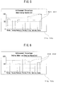
FIG. 5 is a display portion of the remote controller for kitchen and the remote controller for bathroom for displaying achievement percentages of a heating-up operation only; -
FIG. 6 is a display portion of the remote controller for kitchen and the remote controller for bathroom for displaying achievement percentages of an adding water and heating operation only; -
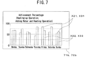
FIG. 7 is a display portion of the remote controller for kitchen and the remote controller for bathroom for displaying achievement percentages of the heating-up operation and achievement percentage of the adding water and heating operation respectively. - 70 ... controller, 71 ... remote controller for kitchen, 71a...
switch, 71b... display portion, 72 ... remote controller for bathroom, 72a ... switch, 72d ... display portion, X1... achievement rate, X2, X3... achievement percentage. -
FIGS. 1 and 2 show a first embodiment of the present invention.
FIG. 1 is a schematic configuration view of a hot water supply apparatus,FIG. 2 is a display portion of a remote controller for kitchen and a remote controller for bathroom for showing an achievement rate. - The hot water supply apparatus comprises a
heat pump unit 10 for heating water using electrical power, atank unit 20 for storing hot water heated by theheat pump unit 10, awater supply pipe 30 for supplying water to thetank unit 20, to a bathroom, and to a kitchen, a hotwater supply pipe 40 for supplying hot water stored in thetank unit 20 to the bathroom and the kitchen, afirst circulation circuit 50 for circulating water between theheat pump unit 10 andtank unit 20, and asecond circulation circuit 60 for circulating water in abathtub 61 between thetank unit 20 and thebathtub 61 in the bathroom. This hot water supply apparatus is to store hot water heated by theheat pump unit 10 in thetank unit 20 so that hot water stored in thetank unit 20 is supplied for washing dishes in the kitchen, for bathing in the bathroom, and etc., and also hot water stored in thetank unit 20 is supplied as a heat source for reheating stored hot water in thebathtub 61. - The
heat pump unit 10 comprises an electrically-powered compressor 11, a gas cooler 12, anexpansion valve 13, and anevaporator 14, which are connected in series by pipes made by copper or stainless steel so as to configure a refrigerant circuit 10a. Also, the refrigerant circuit 10a is filled with carbon dioxide as a refrigerant of which high-pressure side becomes in a supercritical state. The gas cooler 12 is a refrigerant-water heat exchanger in which a flow passage on a water side forms a part of thefirst circulation circuit 50. Theevaporator 14 is a refrigerant-air heat exchanger, and a fan 14a is provided in vicinity of theevaporator 14 so that air which conducts heat exchange with the refrigerant in theevaporator 14 can flow through the evaporator. - The
tank unit 20 comprises a hot water storage tank 21, areheating heat exchanger 22 for conducting heat exchange between water in thebathtub 61, which flows through thesecond circulation circuit 60, and hot water in the hot water storage tank 21, and athird circulation circuit 23 for circulating hot water between the hot water storage tank 21 and thereheating heat exchanger 22. - The hot water storage tank 21 is made of stainless steel or fiber reinforced plastic (FRP), etc., and is covered with a heat insulating material such as glass-wool, foamed urethane, or etc. so as to prevent heat radiation of a stored hot water. Also, in this embodiment, as the hot water storage tank 21, a 370 liters tank is used.
- The
reheating heat exchanger 22 is a water-water heat exchanger, and one side of its flow passage of the reheatingheat exchanger 22 is a part of thesecond circulation circuit 60, and the other side of the flow passage of the reheatingheat exchanger 22 is a part of thethird circulation circuit 23. - The
third circulation circuit 23 is configured by connecting in series an upper part of the hot water storage tank 21, thereheating heat exchanger 22, a circulation pump 23a, and a lower part of the hot water storage tank 21 by copper pipes or stainless steel pipes. Hot water in the upper part of the hot water storage tank 21 returns to the lower part of the hot water storage tank 21 via thereheating heat exchanger 22 by the circulation pump 23a. - The
water supply pipe 30 comprises a firstwater supply pipe 31 connected to the lower part of the hot water storage tank 21, a second water supply pipe 32 connected to the hotwater supply pipe 40, and a thirdwater supply pipe 33 connected to faucets A in the bathroom and the kitchen. A pressure reducing valve 30a is provided on thewater supply pipe 30 which is located at an upper stream side relative to the first, second, and thirdwater supply pipes - The hot
water supply pipe 40 comprises a first hotwater supply pipe 41, one side of which is connected to the upper part of the hot water storage tank 21 and the other side of which is connected to a first mixing valve 40a and a second mixing valve 40b for mixing hot water in the hot water storage tank 21 with water which flows through the second water supply pipe 32, a second hotwater supply pipe 42, one side of which is connected to the first mixing valve 40a and the other side of which is connected to the faucets A in the bathroom and the kitchen, and a third hotwater supply pipe 43, one side of which is connected to the second mixing valve 40b and the other side of which is connected to thesecond circulation circuit 60. Hot water in the upper part of the hot water storage tank 21 flows through the hotwater supply pipe 40 in accordance with pressure of water flows into the hot water storage tank 21 from the firstwater supply pipe 31. Also, on the third hotwater supply pipe 43, a solenoid valve 43a for opening and closing the flow passage of the third hotwater supply pipe 43 is provided. - The
first circulation circuit 50 is configured by connecting in series the lower part of the hot water storage tank 21, acirculation pump 51, the gas cooler 12, and the upper part of the hot water storage tank 21 by copper pipes, stainless steel pipes, vulcanized polyethylene pipes, or etc., water in the lower part of the hot water storage tank 21 flows into the upper part of the hot water storage tank 21 via the gas cooler 12 by thecirculation pump 51. - The
second circulation circuit 60 is configured by connecting in series thebathtub 61, the circulation pump 62, thereheating heat exchanger 22, and thebathtub 61 by copper pipes, stainless steel pipes, vulcanized polyethylene pipes, or etc., water in thebathtub 61 returns to thebathtub 61 via thereheating heat exchanger 22 by the circulation pump 62. - Also, electric power for operating the hot water supply apparatus is supplied from an electric power company, which is a combination of an electric power generated by a plurality of methods, such as thermal power generation, nuclear power generation, water power generation, and etc. Also, the electric power supplied from the electric power company during day time (for example, 7:00∼23:00) is mainly generated by thermal power generation and nuclear power generation, and the electric power supplied from the electric power company during night time (for example, 23:00∼7:00) the electrical power generated mainly by nuclear power generation. An emitted amount of carbon dioxide from nuclear power generation is smaller than an emitted amount of carbon dioxide from thermal power generation. Therefore, the emitted amount of carbon dioxide when generating electric power which is supplied during night time (for example, 0.260 kgCO2/kWh is smaller than an emitted amount of carbon dioxide when generating electric power which is supplied during day time (for example, 0.357 kgCO2/kMh). Also, regarding electric power supplied from electric power company, charges for electric power during night time (for example 7:00-23:00, 8 yen/kWh) is set up to be cheaper than charges for electric power during day time (for example 23:00-7:00, 26 yen/kWh).
- Also, this hot water supply apparatus comprises a
controller 70 provided in thetank unit 20 for controlling operations, a remote controller forkitchen 71, and a remote controller forbathroom 72 provided respectively in a kitchen and a bathroom so as to control and set up the operations. - The
controller 70 comprises a microcomputer of which a memory of the microcomputer memorizes settings for operations and operation modes, and memorizes programs for calculating achievement rates of actual operations compared with an operation set up as an ideal operation, and the programs display on a display portion, which is described below, of the remote controller for thekitchen 71 and the remote controller for thebathroom 72 the calculated results. Also, the memory memorizes data relating to passed operation statuses such as data of passed periods in which the adding water and heating operations are operated and data of amount of water when the adding water and heating operations are operated. Also, thecontroller 70 is capable of selecting an appropriate operation mode so as to operate effectively based on, for example, an actual status of using hot water compared with a passed operation status such as temperature of hot water stored in the hot water storage tank 21. - The
controller 70 is connected toflow sensors 73 for measuring an amount of water heated by aheat pump unit 10. Thesensors 73 are provided on the remote controller forkitchen 71, the remote controller forbathroom 72, and thefirst circulation circuit 50. - The remote controller for
kitchen 71 and the remote controller forbathroom 72 are connected to thecontroller 70 by communication cables respectively, the remote controller forkitchen 71 and the remote controller forbathroom 72 respectively comprises a switch for operations relating to, for example, supplying hot water to thebathtub 61 or reheating the hot water, a switch for setting temperature which is used to set up temperature of hot water to be supplied, a priority switch for changing a priority relating to the remote controllers for kitchen and bathroom, a plurality of switches 71a and 72a such as a communication switch for having conversations between a person in the kitchen and a person in the bathroom, and adisplays - Displays of the
displays switches 71a and 72b. Thedisplays 71a, 71b display the achievement rates of actual operations compared with set-up ideal operations day by day including the day and the past six days. - In the above described hot water supply apparatus, the compressor 11, the fan 14a, and the
circulation pump 51 are operated so as to conduct the heating-up operation for heating water by using night-time electric power and to conduct the adding water and heating operation for adding water and heating the added water when the amount of the remaining hot water in the hot water storage tank 21 becomes less than a predetermined amount. By this, a refrigerant discharged from the compressor 11 absorbs heat by flowing into theevaporator 14 via theexpansion valve 13 after radiating heat by passing through the gas cooler 12, and is suck up by the compressor 11. Also, water in the lower part of the hot water storage tank 21 passes through thefirst circulation circuit 50 by thecirculation pump 51, the water is heated in the gas cooler 12 by exchanging heat with the refrigerant, and is stored in the upper part of the hot water storage tank 21. When a predetermined amount of hot water at the predetermined temperature is stored in the hot water storage tank 21, the operations of the compressor 11, the fan 14a, and thecirculation pump 51 are stopped. - As to the heating-up operation, according to the operation modes, temperature of hot water stored in the hot water storage tank 21 is set up within 65∼90°C, and the amount of hot water to be stored in the hot water storage tank 21 is set up within 370 liters to 320 liters. Also, as to the adding water and heating operation, temperature of hot water stored in the hot water storage tank 21 is set up to be a set-up temperature of the immediately preceded heating-up operation.
- As to the heating-up operation, to prevent the hot water storage tank 21 from emitting heat, the
controller 70 starts the heating-up operation by a time which is calculated reversely so that the heating-up operation is completed by the time when the night-time electric power supply is stopped. For example, if it takes five hours to fill water at a predetermined temperature in the hot water storage tank 21 by the heating-up operation, the heating-up operation starts on 2:00 and finishes at 7:00. - Also, hot water in the upper part of the hot water storage tank 21 passes through the first hot
water supply pipe 41, then, by the first mixing valve 40a, the hot water is mixed with water which passes through the second water supply pipe 32 and temperature of the mixed hot water becomes the set-up temperature set up by the remote controller forkitchen 71 or the remote controller forbathroom 72, the hot water flows through the second hotwater supply pipe 42, and the hot water is supplied from the faucet A in the kitchen or in the bathroom. - Also, hot water in the upper part of the hot water storage tank 21 passes through the first hot
water supply pipe 41, then, by the second mixing valve 40b, the hot water is mixed with water passes through the second water supply pipe 32 and temperature of the mixed hot water becomes the set-up temperature set up by the remote controller forkitchen 71 or the remoter controller forbathroom 72, the hot water flows through the third hotwater supply pipe 43 and thesecond circulation circuit 60, and the hot water is supplied to thebathtub 61 when thebathtub 61 is to be filled with hot water. - Also, as to a reheating operation, by operating the circulation pumps 23a and 62, hot water in the
bathtub 61 is circulated by thesecond circulation circuit 60, and hot water in the hot water storage tank 21 is circulated by thethird circulation circuit 23. By this, hot water in thebathtub 61 is heated at the reheating heat exchanger 21 by exchanging heat with hot water in the upper part of the hot water storage tank 21 and flows back to thebathtub 61. - A method for calculating an achievement rate X1 of an actual operation compared with a set-up ideal operation is explained below. The achievement rate X1 is calculated by subtracting a value which is calculated by multiplying an amount of water A (liters), which is the amount of water heated by the heating-up operation, and a value B (1/liters), which is the value per 1 liter, and a coefficient K (for example, 7:00∼23:00=1, 23:00∼7:00 = 0.3) relating to periods in which the heating-up operation is operated from a
value 100 defined as an ideal set-up operation of the adding water and heating operation. - For example, when B = 0.5, K = 1(7:00∼23:00), 0.3(23:00∼7:00), for twenty four hours as one unit, if 50 liters of water is heated during 7:00-23:00, and 30 liters of water is heated during 23:00∼7:00 by the adding water and heating operation, the calculation will be the achievement rate X1 = 100-50(liters) × 0.5(1/liters) × 1-30 (liters) × 0.5(1/liters) × 0.3=60.5. In other word, the value of the achievement rate X1 becomes 100 if the adding water and heating operation is not conducted for twenty four hours. And the more the amount of water heated by the adding water and heating operation increase, the smaller the value of the achievement rate X becomes. Also, the value of the achievement rate X1 becomes smaller if the adding water and heating operation is conducted during 7:00∼23:00 compared with the adding water and heating operation conducted during 23:00∼7:00 even though amount of water heated by the adding water and heating operation is the same.
- The coefficient K becomes different between the time period 7:00∼23:00 and the time period 23:00∼7:00 considering that charges for electric power are different and emitting amounts of carbon dioxide when generating energy are different according to the time periods. In other word, during 7:00-23:00, the charge for electric power is higher and the emitting amount of carbon dioxide when generating energy is larger. Also, during 23:00-7:00, the charge for electric power is cheaper and the emitting amount of carbon dioxide when generating energy is smaller. Therefore, if a time table for the charges for electric power and a time table for the emitting amount of carbon dioxide when generating energy are different each other, the coefficient K should be set up based on the conditions thereof respectively.
- Also, as shown in
FIG.2 , the achievement rates X1 which are calculated by thecontroller 70 are displayed on thedisplay portions - By the hot water supply apparatus of this embodiment, the achievement rate X1 of an actual operation compared with the set-up ideal operation is calculated based on the operation information memorized in the memory, the calculated achievement rates X1 are displayed on the
display portions kitchen 71 and the remote controller forbathroom 72. By this, it is easy to know the status of the actual operation compared with the set-up ideal operation. Therefore, it becomes possible to facilitate the energy saving by notifying users of the status of the actual operation compared with the set-up ideal operation. -
FIGS.3-7 show the second embodiment of the present invention.FIG. 3 is a schematic configuration view of the hot water supply apparatus.FIG.4 is a display portion of the remote controller for kitchen and remote controller for bathroom for displaying achievement percentages.FIG.5 is a display portion of the remote controller for kitchen and remote controller for bathroom for displaying achievement percentages by conducting the heating-up operation only.FIG.6 is a display portion of the remote controller for kitchen and the remote controller for bathroom for displaying achievement percentages by conducting the adding water and heating operation only.FIG.7 is a display portion of the remote controller for kitchen and the remote controller for bathroom for displaying sequentially the achievement percentages by conducting the heating-up operation and the adding water and heating operation respectively. Also, the compositions which are the same to the ones in the previously explained first embodiment are assigned the same symbols. - The
controller 70 of this hot water supply apparatus is connected with afirst temperature sensor 74 for detecting temperature of water before heated by theheat pump unit 10 and a second temperature sensor 75 provided on theheat pump unit 10 for detecting outside-air temperature. - The
controller 70 memorizes data obtained, for example, by an experiment about a power consumption amount W(Wh) of theheat pump unit 10 when heating a water F(1) being at a water temperature Tb(°C) and at a outside-air temperature Ta(°C) to become an objective temperature Tc(°C), and/or by a passed actual operation data. Based on the detected temperature T1 of thefirst temperature sensor 74 and the detected temperature T2 of the second temperature sensor 75, the power consumption amount W(Wh) for heating water to the objective temperature Tc( °C ) is calculated. - Also, the
controller 70 calculates emitted amounts of carbon dioxide C(kg) and charges for electric power R(yen) based on the power consumption amounts W(Wh) for conducting the heating-up operation and the adding water and heating operation, and time periods in which the heating-up operation is conducted. Also, the achievement percentages X2 and X3 are calculated as the achievement rates of an actual operation compared with the most effective operation in respect of the emitting amount of carbon dioxide C(kg) and charges for electric power R(yen) respectively. Also, thecontroller 70 displays the achievement percentages X2 and X3 of the emitted amounts of carbon dioxide C(kg) and the charges for electric power R(yen) on thedisplay portions kitchen 71 and the remote controller forbathroom 72. - By the above-mentioned hot water supply apparatus, the
controller 70 calculates an achievement percentage X21 of the heating-up operations as follows. Thecontroller 70 calculates a presumed power consumption amount W1(Wh) for heating water F1(liters) being at a detected temperature T1(°C) detected by thefirst temperature sensor 74, when the second temperature sensor 75 detects a temperature at a detected temperature T2(°C), to an objective temperature Tc1(°C), and based on the calculated power consumption amount W1(Wh), a presumed emitting amount of carbon dioxide C1(kg) (for example, 0.260 kgCO2/kWh generated by an actual heating-up operation is calculated. Also thecontroller 70 calculates a presumed emitting amount of carbon dioxide Cmin(kg) generated by conducting the most effective heating-up operation (for example, water temperature is at 65°C, stored water amount is 320 liters), and a presumed emitted amount of carbon dioxide Cmax(kg) generated by conducting the least effective heating-up operation (for example, water temperature is at 90°C, stored water amount is 370 liters) based on the detected temperature T1(°C) of thefirst temperature sensor 74 and the detected temperature T2(°C) of the second temperature sensor 75. Moreover, thecontroller 70 calculates the achievement percentage X21 from a presumed emitting amount of carbon dioxide C1(kg) which will be generated from the actual heating-up operation, the presumed emitting amount of carbon dioxide Cmin(kg) generated from the most effective heating-up operation, and the presumed emitting amount of carbon dioxide Cmax1(kg) generated from the least effective heating-up operation, like the achievement percentage X21=(Cmax1-C1) / (Cmax1-Cmin) X100. - Also, the
controller 70 calculates an achievement percentage X22 relating to the adding water and heating operation as follows. At each time in which the adding water and heating operation is conducted, thecontroller 70 calculates a presumed power consumption amount W2(Wh) for heating water F2(liters) being at a detected temperature T1(°C) detected by thefirst temperature sensor 74, when the second temperature sensor 75 detects a temperature T2(°C), to an objective temperature Tc1(°C), and based on the calculated power consumption amount W2(kg), a presumed emitting amount of carbon dioxide C2(kg) generated from an actual adding water and heating operation is calculated. At this time, since emitting amounts of carbon dioxide C21(kg) for each unit power become different depending on time periods in which the adding water and heating operation is conducted, a presumed emitting amount of carbon dioxide C21(kg) generated from the adding water and heating operation conducted during 7:00∼23:00 (for example, 0.357 kgCO2/kWh) and a presumed emitting amount of carbon dioxide C22(kg) generated from the adding water and heating operation conducted during 23:00∼7:00 (for example, 0.260 kgCO2/kWh) are calculated respectively. Also, thecontroller 70 calculates a presumed emitting amount of carbon dioxide Cmax2(kg) generated from the least effective adding water and heating operation (for example, the adding water and heating operation during the time period of 7:00∼23:00 with added water amount of 700 liters) based on the detected temperature T1(°C) detected by thefirst temperature sensor 74 and the detected temperature T2(°C) detected by the second temperature sensor 75. Moreover, thecontroller 70 calculates an achievement percentage X22 from presumed amounts of CO2 emission C1(kg) and C2(kg) generated from actual adding water and heating operations, and the presumed emitting amount of carbon dioxide Cmax(kg) generated from the least effective adding water heating operation, like the achievement percentage X22= ((Cmax2-C21-C22)/Cmax2) ×100. - Therefore, the achievement percentage X2 of an emitted amount of carbon dioxide generated both by the heating-up operation and the adding water and heating operation is calculated like ×2= ((Cmax1-C1) +(Cmax2-C21-C22)) / ((Cmax-Cmin) +Cmax2) ×100.
- Also, the
controller 70 calculates an achievement percentage X3 of a charge for electric power R(yen) like calculating the achievement percentage X2 of an emitted amount of carbon dioxide C(kg). Thecontroller 70 calculates the achievement percentage X31 of the heating-up operation as follows. Thecontroller 70 calculates a presumed power consumption amount W1(Wh) for heating water F1(liters) being at a detected temperature T1(°C) detected by thefirst temperature sensor 74, when the second temperature sensor 75 detects a temperature T2( °C ), to an objective temperature Tc1(°C), and based on the calculated consumption power amount W1(Wh), a charge for electric power R1(yen) for an actual heating-up operation is calculated (for example, 8 yen/kWh). Also, thecontroller 70 calculates a presumed charge for electric power Rmin(yen) for the most effective heating-up operation (for example, water temperature is at 65°C with stored water amount of 320 liters) and a presumed charge for electric power Rmax1(yen) for the least effective heating-up operation (for example, water temperature is at 90°C with stored water amount of 320 liters) based on the detected temperature T1(°C) detected by thefirst temperature sensor 74 and the detected temperature T2(°C) detected by the second temperature sensor 75. Moreover, thecontroller 70 calculates the achievement percentage X31 of the heating-up operation from the presumed charge for electric power R1(yen) for an actual heating-up operation, the presumed charge for electric power Rmin(yen) for the most effective heating-up operation, and the presumed charge for electric power Rmax1(yen) for the least effective heating-up operation, like the achievement percentage X31= (Rmax1-R1) /(Rmax1-Rmin) × 100. - Also, the
controller 70 calculates an achievement percentage X32 as follows. At each time in which the adding water and heating operation is conducted, thecontroller 70 calculates a presumed power consumption amount W2(Wh) for heating water F2(liters) being at a detected temperature T1(°C) detected by thefirst temperature sensor 74, when the second temperature sensor 75 detects a temperature T2(°C), to an objective temperature Tc1(°C), and based on the calculated power consumption amount W2(Wh), a presumed charge for electric power R2(yen) is calculated for an actual adding water and heating operation. At this time, Since presumed charges for electric power for each time period differ according to time periods in which the adding water and heating operation is conducted, a presumed charge for electric power R21(yen) for conducting the adding water and heating operation during 7:00∼23:00 (for example, 26 yen/kWh), and a presumed charge for electric power R22 for conducting the adding water and heating operation during 23:00∼7:00 (for example, 8 yen/kWh) are calculated respectively. Also, thecontroller 70 calculates a presumed charge for electric power Rmax2(yen) for the least effective adding water and heating operation (for example, the adding water and heating operation during the time period of 7:00∼23:00 with added water amount of 700 liters) based on the detected temperature T1(°C) detected by thefirst temperature sensor 74 and the detected temperature T2 (°C) detected by the second temperature sensor 75. Moreover, thecontroller 70 calculates the achievement percentage X32 from the presumed charges for electric power R21(yen) and R22(yen) for conducting the actual adding water and heating operation, and the presumed charge for electric power Rmax(yen) for the least effective adding water and heating operation, like the achievement percentage X32= ((Rmax2-R21-R22)/Rmax2) ×100. - By this, an achievement percentage X3 of the charge for electric power R(yen) for conducting both the heating-up operation and the adding water and heating operation is calculated like the achievement percentage X3 = ((Rmax1-R1) + (Rmax-R21-R22)/((Rmax-Rmin) +Rmax2) ×100.
- Moreover, as shown in
FIG.4 , the calculated achievement rates X2 and X3 are displayed on thedisplay portions kitchen 71 and the remote controller forbathroom 72 with bar graphs of which maximum percentages of the achievement percentages X2 and X3 are 100%. The achievement rates X2 and X3 of the past seven days are shown by the bar graphs day by day. By this, it becomes possible to compare the achievement percentages X2 and X3 of the past seven days easily. Also, instead of displaying the achievement percentages X2 and X3, the achievement percentages X21 and X31 for conducting the heating-up operation and the achievement percentages X22 and X32 for conducting the adding water and heating operation can be displayed on thedisplay portions FIGS. 5 and 6 , or the achievement percentages of X21 and X31 for conducting the heating-up operation and the achievement percentages X22 and X32 for adding water and heating operation can be displayed on thedisplay portions FIG.7 . - Also, either the achievement percentage X2 of the emitted amount of carbon dioxide C(kg) or the achievement percentage X3 of the electric charge R(yen) is displayed on the
display portions kitchen 71 and remote controller forbathroom 72, and the other one of the X2 or X3 can be displayed by operating the switches 71a and 72a. - Also, when the achievement percentages X22 and X32 of the adding water and heating operation is higher than a predetermined percentage, the
controller 70 displays on thedisplay portions controller 70 calculates the achievement percentages X2 and X3 of the case in which the operation mode is changed to the one which is with higher temperature of water stored in the hot water storage tank 21 in the heating-up operation, and if the controller judges that it is possible to reduce energy in total, the controller displays an indication showing a suggestion of changing operation modes on thedisplay portions - By the hot water supply apparatus of this embodiment, the achievement percentage X2 of the actual operation compared with a set-up ideal operation based on the stored operation data is calculated, and the calculated achievement percentage X2 is displayed on the
display portions kitchen 71 and the remote controller forbathroom 72. By this, it becomes possible to know the actual operation compared with the set-up ideal operation easily. Therefore, it is capable of facilitating the energy saving by notifying users of the status of the actual operation compared with the set-up ideal operation. - Also, the achievement percentage X2 of the emitted amount of carbon dioxide generated from the actual operation compared with a presumed emitting amount of carbon dioxide which is supposed to be emitted from the set-up ideal operation is calculated, the calculated achievement percentage X2 is displayed on the
display portions kitchen 71 and the remote controller forbathroom 72. By this, it becomes possible to notify users of a status of an actual operation from the aspect of emitted amount of carbon dioxide. Therefore, it becomes possible to improve consciousness of users for energy saving. - Also, the achievement percentage X3 of the charge for electric power for the actual operation compared with a presumed charge for electric power which is supposed to be charged for the set-up ideal operation is calculated, the calculated achievement percentage X3 is displayed on the
display portions kitchen 71 and the remote controller forbathroom 72. By this, it becomes possible to notify users of a status of an actual operation from the economical aspect. Therefore, it becomes possible to improve consciousness of users for economical saving. - Also, the achievement percentage X2 of the emitted amount of carbon dioxide and the achievement percentage X3 of the charge for electric power can be switched and displayed alternatively on the
display portions kitchen 71 and the remote controller forbathroom 72. By this, users can select which one of the achievement percentage X2 of the emitted amount of carbon dioxide or the achievement percentage X3 of the charge for electric power to be displayed according to their needs. Therefore, Therefore, it becomes further effectively possible to improve consciousness of users for energy saving. - Also, the achievement percentages X2 and X3 of the past seven days can be displayed day by day on the
display portions kitchen 71 and the remote controller forbathroom 72. By this, it becomes possible to compare the passed achievement percentages X2 and X3 easily. Therefore, it is capable of facilitating the energy saving further. - Also, based on the passed achievement percentages X2 and X3, the best operation mode can be selected and displayed on the
display portions kitchen 71 and the remote controller forbathroom 72, and operation modes can be changed automatically. By this, it becomes possible to operate by the best operation mode. Therefore, it becomes capable of practicing further energy saving. - The preferred embodiments described in this specification are illustrative and not restrictive. The scope of invention is given by the appended claims, and all changes and modifications included in the meaning of claims are embraced in the present invention.
Claims (6)
- A hot water supply apparatus comprising:a memory (70) for memorizing information relating to a past operation;a calculation portion (70) for calculating an actual achievement rate (X1, X2, X3) of an actual operation compared with a set-up operation based on the information memorized in the memory; anda display portion (71b, 72b) for displaying a calculated result by the calculation portion (70).
- The hot water supply apparatus according to claim 1, wherein
the calculating portion (70) calculates the achievement rate (X2) of an emitted amount of carbon dioxide in the actual operation compared with an emitted amount of carbon dioxide which is supposed to be emitted in the set-up operation. - The hot water supply apparatus according to claim 1, wherein
the calculating portion (70) calculates the achievement rate (X3) of a charge for consumed energy in the actual operation compared with a charge for consumed energy which is supposed to be consumed in the set-up operation. - The hot water supply apparatus according to claim 1 further comprising a display changer (71a, 71a), the hot water supply apparatus wherein
the calculating portion (70) calculates the achievement rate (X2) of an emitted amount of carbon dioxide in the actual operation compared with an emitted amount of carbon dioxide which is supposed to be emitted in the set-up operation, and the calculating portion (70) calculates the achievement rate (X3) of a charge for consumed energy in the actual operation compared with a charge for consumed energy which is supposed to be consumed in the set-up operation,
and the display changer (71a, 71b) is provided for changeably displaying on the display portion (71b,72b) either the achievement rate (X2) of the emitted amount of carbon dioxide or the achievement rate (X3) of the charge for consumed energy. - The hot water supply apparatus according to any one of claims 1-4, wherein
the display portion (71b,72b) displays a series of achievement rates (X1, X2, X3) of a passed predetermined period. - The hot water supply apparatus according to any one of claims 1-5, further comprising:a plurality of operation modes of which a set-up amount of water to be heated, a set-up temperature of heated water, and the like are different each other; anda controller (70) for selecting the best operation mode based on the past achievement rate (X1, X2, X3).
Applications Claiming Priority (2)
| Application Number | Priority Date | Filing Date | Title |
|---|---|---|---|
| JP2007297901A JP2009121781A (en) | 2007-11-16 | 2007-11-16 | Hot water supply apparatus |
| PCT/JP2008/069129 WO2009063727A1 (en) | 2007-11-16 | 2008-10-22 | Hot water supply device |
Publications (3)
| Publication Number | Publication Date |
|---|---|
| EP2228610A1 true EP2228610A1 (en) | 2010-09-15 |
| EP2228610A4 EP2228610A4 (en) | 2011-03-02 |
| EP2228610B1 EP2228610B1 (en) | 2012-05-02 |
Family
ID=40638580
Family Applications (1)
| Application Number | Title | Priority Date | Filing Date |
|---|---|---|---|
| EP08849821A Not-in-force EP2228610B1 (en) | 2007-11-16 | 2008-10-22 | Hot water supply device |
Country Status (5)
| Country | Link |
|---|---|
| EP (1) | EP2228610B1 (en) |
| JP (1) | JP2009121781A (en) |
| AT (1) | ATE556277T1 (en) |
| AU (1) | AU2008322043B2 (en) |
| WO (1) | WO2009063727A1 (en) |
Cited By (2)
| Publication number | Priority date | Publication date | Assignee | Title |
|---|---|---|---|---|
| CN106907755A (en) * | 2017-05-05 | 2017-06-30 | 天津商业大学 | A kind of heating once net and secondary network system for matching low temperature well formula nuclear heat supplying pile |
| CN106949524A (en) * | 2017-05-05 | 2017-07-14 | 天津商业大学 | A kind of heating once net system for matching low temperature well formula nuclear heat supplying pile |
Families Citing this family (3)
| Publication number | Priority date | Publication date | Assignee | Title |
|---|---|---|---|---|
| JP2011145008A (en) * | 2010-01-14 | 2011-07-28 | Mitsubishi Electric Corp | Remote controller for air conditioning |
| JP5446906B2 (en) * | 2010-01-18 | 2014-03-19 | 三菱電機株式会社 | Air conditioner |
| JP2012007834A (en) * | 2010-06-25 | 2012-01-12 | Aisin Seiki Co Ltd | Air conditioner group controller |
Family Cites Families (10)
| Publication number | Priority date | Publication date | Assignee | Title |
|---|---|---|---|---|
| DK0686836T3 (en) * | 1994-06-10 | 1997-07-14 | Landis & Gyr Tech Innovat | heat meter |
| JP2000274809A (en) | 1999-03-18 | 2000-10-06 | Toto Ltd | Hot water supply apparatus |
| JP2003250224A (en) * | 2001-12-19 | 2003-09-05 | Sekisui Chem Co Ltd | Cogeneration system |
| JP4504635B2 (en) * | 2003-06-18 | 2010-07-14 | 積水化学工業株式会社 | Cogeneration system |
| JP4295655B2 (en) * | 2004-03-31 | 2009-07-15 | 株式会社ガスター | Combined hot water supply system |
| JP2005332103A (en) * | 2004-05-19 | 2005-12-02 | Tokyu Construction Co Ltd | Carbon dioxide reduction target value display system |
| JP2006013780A (en) * | 2004-06-24 | 2006-01-12 | Noritz Corp | Information terminal |
| JP4484632B2 (en) * | 2004-08-30 | 2010-06-16 | 株式会社ノーリツ | Heat source control device |
| DE102004054118B4 (en) * | 2004-11-08 | 2009-01-29 | Hydrometer Gmbh | Method for operating a heat meter |
| JP2006349483A (en) * | 2005-06-15 | 2006-12-28 | Cosmo Life Kk | Electric power consumption monitoring system |
-
2007
- 2007-11-16 JP JP2007297901A patent/JP2009121781A/en active Pending
-
2008
- 2008-10-22 AU AU2008322043A patent/AU2008322043B2/en not_active Ceased
- 2008-10-22 AT AT08849821T patent/ATE556277T1/en active
- 2008-10-22 EP EP08849821A patent/EP2228610B1/en not_active Not-in-force
- 2008-10-22 WO PCT/JP2008/069129 patent/WO2009063727A1/en not_active Ceased
Cited By (2)
| Publication number | Priority date | Publication date | Assignee | Title |
|---|---|---|---|---|
| CN106907755A (en) * | 2017-05-05 | 2017-06-30 | 天津商业大学 | A kind of heating once net and secondary network system for matching low temperature well formula nuclear heat supplying pile |
| CN106949524A (en) * | 2017-05-05 | 2017-07-14 | 天津商业大学 | A kind of heating once net system for matching low temperature well formula nuclear heat supplying pile |
Also Published As
| Publication number | Publication date |
|---|---|
| EP2228610B1 (en) | 2012-05-02 |
| JP2009121781A (en) | 2009-06-04 |
| AU2008322043A1 (en) | 2009-05-22 |
| WO2009063727A1 (en) | 2009-05-22 |
| AU2008322043B2 (en) | 2011-10-13 |
| ATE556277T1 (en) | 2012-05-15 |
| EP2228610A4 (en) | 2011-03-02 |
Similar Documents
| Publication | Publication Date | Title |
|---|---|---|
| KR101329509B1 (en) | Hot water circulation system associated with heat pump and method for controlling the same | |
| EP2228610B1 (en) | Hot water supply device | |
| US20090250203A1 (en) | Hot Water Supply Apparatus | |
| JP5277714B2 (en) | Water heater | |
| JP5494422B2 (en) | Hot water storage hot water supply system | |
| JP5569581B2 (en) | Hot water storage hot water supply system | |
| JP2006336937A (en) | Hot water storage water heater | |
| JP5109300B2 (en) | Hot water storage hot water heater | |
| JP6036016B2 (en) | Heat pump hot water supply system | |
| KR101517234B1 (en) | Hot water circulation system associated with heat pump and method for controlling the same | |
| JP3868909B2 (en) | Hot water storage water heater | |
| JP2005147557A (en) | Water heater | |
| KR20100042104A (en) | A method of working cope with trouble for hot water circulation system associated with heat pump | |
| JP3869426B2 (en) | Hot water storage water heater | |
| JP5003616B2 (en) | Hot water system | |
| EP1972860A2 (en) | Hot water supply apparatus | |
| JP4155162B2 (en) | Hot water storage water heater | |
| JP2015094569A (en) | Display device for floor heating | |
| JP6502562B1 (en) | Power generation system | |
| KR101456716B1 (en) | Method for controlling hot water circulation system associated with heat pump | |
| JP4207867B2 (en) | Hot water storage water heater | |
| JP7514423B2 (en) | Heat pump hot water supply system | |
| EP2233856A1 (en) | Hot-water supply apparatus | |
| JP3855942B2 (en) | Hot water storage water heater | |
| JP5023607B2 (en) | Hot water supply apparatus and control method thereof |
Legal Events
| Date | Code | Title | Description |
|---|---|---|---|
| PUAI | Public reference made under article 153(3) epc to a published international application that has entered the european phase |
Free format text: ORIGINAL CODE: 0009012 |
|
| 17P | Request for examination filed |
Effective date: 20100615 |
|
| AK | Designated contracting states |
Kind code of ref document: A1 Designated state(s): AT BE BG CH CY CZ DE DK EE ES FI FR GB GR HR HU IE IS IT LI LT LU LV MC MT NL NO PL PT RO SE SI SK TR |
|
| AX | Request for extension of the european patent |
Extension state: AL BA MK RS |
|
| DAX | Request for extension of the european patent (deleted) | ||
| A4 | Supplementary search report drawn up and despatched |
Effective date: 20110127 |
|
| RIC1 | Information provided on ipc code assigned before grant |
Ipc: F24H 1/00 20060101AFI20090608BHEP Ipc: F24D 19/10 20060101ALI20110121BHEP Ipc: H04Q 9/00 20060101ALI20110121BHEP Ipc: F24H 1/18 20060101ALI20110121BHEP |
|
| GRAP | Despatch of communication of intention to grant a patent |
Free format text: ORIGINAL CODE: EPIDOSNIGR1 |
|
| GRAS | Grant fee paid |
Free format text: ORIGINAL CODE: EPIDOSNIGR3 |
|
| GRAA | (expected) grant |
Free format text: ORIGINAL CODE: 0009210 |
|
| AK | Designated contracting states |
Kind code of ref document: B1 Designated state(s): AT BE BG CH CY CZ DE DK EE ES FI FR GB GR HR HU IE IS IT LI LT LU LV MC MT NL NO PL PT RO SE SI SK TR |
|
| REG | Reference to a national code |
Ref country code: GB Ref legal event code: FG4D |
|
| REG | Reference to a national code |
Ref country code: AT Ref legal event code: REF Ref document number: 556277 Country of ref document: AT Kind code of ref document: T Effective date: 20120515 Ref country code: CH Ref legal event code: EP |
|
| REG | Reference to a national code |
Ref country code: IE Ref legal event code: FG4D |
|
| REG | Reference to a national code |
Ref country code: DE Ref legal event code: R096 Ref document number: 602008015446 Country of ref document: DE Effective date: 20120705 |
|
| REG | Reference to a national code |
Ref country code: NL Ref legal event code: VDEP Effective date: 20120502 |
|
| REG | Reference to a national code |
Ref country code: LT Ref legal event code: MG4D Effective date: 20120502 |
|
| PG25 | Lapsed in a contracting state [announced via postgrant information from national office to epo] |
Ref country code: PL Free format text: LAPSE BECAUSE OF FAILURE TO SUBMIT A TRANSLATION OF THE DESCRIPTION OR TO PAY THE FEE WITHIN THE PRESCRIBED TIME-LIMIT Effective date: 20120502 Ref country code: CY Free format text: LAPSE BECAUSE OF FAILURE TO SUBMIT A TRANSLATION OF THE DESCRIPTION OR TO PAY THE FEE WITHIN THE PRESCRIBED TIME-LIMIT Effective date: 20120502 Ref country code: LT Free format text: LAPSE BECAUSE OF FAILURE TO SUBMIT A TRANSLATION OF THE DESCRIPTION OR TO PAY THE FEE WITHIN THE PRESCRIBED TIME-LIMIT Effective date: 20120502 Ref country code: IS Free format text: LAPSE BECAUSE OF FAILURE TO SUBMIT A TRANSLATION OF THE DESCRIPTION OR TO PAY THE FEE WITHIN THE PRESCRIBED TIME-LIMIT Effective date: 20120902 Ref country code: NO Free format text: LAPSE BECAUSE OF FAILURE TO SUBMIT A TRANSLATION OF THE DESCRIPTION OR TO PAY THE FEE WITHIN THE PRESCRIBED TIME-LIMIT Effective date: 20120802 Ref country code: SE Free format text: LAPSE BECAUSE OF FAILURE TO SUBMIT A TRANSLATION OF THE DESCRIPTION OR TO PAY THE FEE WITHIN THE PRESCRIBED TIME-LIMIT Effective date: 20120502 Ref country code: FI Free format text: LAPSE BECAUSE OF FAILURE TO SUBMIT A TRANSLATION OF THE DESCRIPTION OR TO PAY THE FEE WITHIN THE PRESCRIBED TIME-LIMIT Effective date: 20120502 |
|
| REG | Reference to a national code |
Ref country code: AT Ref legal event code: MK05 Ref document number: 556277 Country of ref document: AT Kind code of ref document: T Effective date: 20120502 |
|
| PG25 | Lapsed in a contracting state [announced via postgrant information from national office to epo] |
Ref country code: PT Free format text: LAPSE BECAUSE OF FAILURE TO SUBMIT A TRANSLATION OF THE DESCRIPTION OR TO PAY THE FEE WITHIN THE PRESCRIBED TIME-LIMIT Effective date: 20120903 Ref country code: LV Free format text: LAPSE BECAUSE OF FAILURE TO SUBMIT A TRANSLATION OF THE DESCRIPTION OR TO PAY THE FEE WITHIN THE PRESCRIBED TIME-LIMIT Effective date: 20120502 Ref country code: GR Free format text: LAPSE BECAUSE OF FAILURE TO SUBMIT A TRANSLATION OF THE DESCRIPTION OR TO PAY THE FEE WITHIN THE PRESCRIBED TIME-LIMIT Effective date: 20120803 Ref country code: HR Free format text: LAPSE BECAUSE OF FAILURE TO SUBMIT A TRANSLATION OF THE DESCRIPTION OR TO PAY THE FEE WITHIN THE PRESCRIBED TIME-LIMIT Effective date: 20120502 Ref country code: SI Free format text: LAPSE BECAUSE OF FAILURE TO SUBMIT A TRANSLATION OF THE DESCRIPTION OR TO PAY THE FEE WITHIN THE PRESCRIBED TIME-LIMIT Effective date: 20120502 |
|
| PG25 | Lapsed in a contracting state [announced via postgrant information from national office to epo] |
Ref country code: BE Free format text: LAPSE BECAUSE OF FAILURE TO SUBMIT A TRANSLATION OF THE DESCRIPTION OR TO PAY THE FEE WITHIN THE PRESCRIBED TIME-LIMIT Effective date: 20120502 |
|
| PG25 | Lapsed in a contracting state [announced via postgrant information from national office to epo] |
Ref country code: DK Free format text: LAPSE BECAUSE OF FAILURE TO SUBMIT A TRANSLATION OF THE DESCRIPTION OR TO PAY THE FEE WITHIN THE PRESCRIBED TIME-LIMIT Effective date: 20120502 Ref country code: CZ Free format text: LAPSE BECAUSE OF FAILURE TO SUBMIT A TRANSLATION OF THE DESCRIPTION OR TO PAY THE FEE WITHIN THE PRESCRIBED TIME-LIMIT Effective date: 20120502 Ref country code: SK Free format text: LAPSE BECAUSE OF FAILURE TO SUBMIT A TRANSLATION OF THE DESCRIPTION OR TO PAY THE FEE WITHIN THE PRESCRIBED TIME-LIMIT Effective date: 20120502 Ref country code: EE Free format text: LAPSE BECAUSE OF FAILURE TO SUBMIT A TRANSLATION OF THE DESCRIPTION OR TO PAY THE FEE WITHIN THE PRESCRIBED TIME-LIMIT Effective date: 20120502 Ref country code: AT Free format text: LAPSE BECAUSE OF FAILURE TO SUBMIT A TRANSLATION OF THE DESCRIPTION OR TO PAY THE FEE WITHIN THE PRESCRIBED TIME-LIMIT Effective date: 20120502 Ref country code: RO Free format text: LAPSE BECAUSE OF FAILURE TO SUBMIT A TRANSLATION OF THE DESCRIPTION OR TO PAY THE FEE WITHIN THE PRESCRIBED TIME-LIMIT Effective date: 20120502 Ref country code: NL Free format text: LAPSE BECAUSE OF FAILURE TO SUBMIT A TRANSLATION OF THE DESCRIPTION OR TO PAY THE FEE WITHIN THE PRESCRIBED TIME-LIMIT Effective date: 20120502 |
|
| PLBE | No opposition filed within time limit |
Free format text: ORIGINAL CODE: 0009261 |
|
| STAA | Information on the status of an ep patent application or granted ep patent |
Free format text: STATUS: NO OPPOSITION FILED WITHIN TIME LIMIT |
|
| 26N | No opposition filed |
Effective date: 20130205 |
|
| PG25 | Lapsed in a contracting state [announced via postgrant information from national office to epo] |
Ref country code: ES Free format text: LAPSE BECAUSE OF FAILURE TO SUBMIT A TRANSLATION OF THE DESCRIPTION OR TO PAY THE FEE WITHIN THE PRESCRIBED TIME-LIMIT Effective date: 20120813 |
|
| REG | Reference to a national code |
Ref country code: DE Ref legal event code: R097 Ref document number: 602008015446 Country of ref document: DE Effective date: 20130205 |
|
| PG25 | Lapsed in a contracting state [announced via postgrant information from national office to epo] |
Ref country code: MC Free format text: LAPSE BECAUSE OF NON-PAYMENT OF DUE FEES Effective date: 20121031 |
|
| REG | Reference to a national code |
Ref country code: CH Ref legal event code: PL |
|
| GBPC | Gb: european patent ceased through non-payment of renewal fee |
Effective date: 20121022 |
|
| REG | Reference to a national code |
Ref country code: IE Ref legal event code: MM4A |
|
| PG25 | Lapsed in a contracting state [announced via postgrant information from national office to epo] |
Ref country code: IE Free format text: LAPSE BECAUSE OF NON-PAYMENT OF DUE FEES Effective date: 20121022 Ref country code: CH Free format text: LAPSE BECAUSE OF NON-PAYMENT OF DUE FEES Effective date: 20121031 Ref country code: GB Free format text: LAPSE BECAUSE OF NON-PAYMENT OF DUE FEES Effective date: 20121022 Ref country code: BG Free format text: LAPSE BECAUSE OF FAILURE TO SUBMIT A TRANSLATION OF THE DESCRIPTION OR TO PAY THE FEE WITHIN THE PRESCRIBED TIME-LIMIT Effective date: 20120802 Ref country code: LI Free format text: LAPSE BECAUSE OF NON-PAYMENT OF DUE FEES Effective date: 20121031 |
|
| PG25 | Lapsed in a contracting state [announced via postgrant information from national office to epo] |
Ref country code: MT Free format text: LAPSE BECAUSE OF FAILURE TO SUBMIT A TRANSLATION OF THE DESCRIPTION OR TO PAY THE FEE WITHIN THE PRESCRIBED TIME-LIMIT Effective date: 20120502 |
|
| PGFP | Annual fee paid to national office [announced via postgrant information from national office to epo] |
Ref country code: DE Payment date: 20131021 Year of fee payment: 6 Ref country code: FR Payment date: 20131022 Year of fee payment: 6 |
|
| PGFP | Annual fee paid to national office [announced via postgrant information from national office to epo] |
Ref country code: IT Payment date: 20131023 Year of fee payment: 6 |
|
| PG25 | Lapsed in a contracting state [announced via postgrant information from national office to epo] |
Ref country code: TR Free format text: LAPSE BECAUSE OF FAILURE TO SUBMIT A TRANSLATION OF THE DESCRIPTION OR TO PAY THE FEE WITHIN THE PRESCRIBED TIME-LIMIT Effective date: 20120502 |
|
| PG25 | Lapsed in a contracting state [announced via postgrant information from national office to epo] |
Ref country code: LU Free format text: LAPSE BECAUSE OF NON-PAYMENT OF DUE FEES Effective date: 20121022 |
|
| PG25 | Lapsed in a contracting state [announced via postgrant information from national office to epo] |
Ref country code: HU Free format text: LAPSE BECAUSE OF FAILURE TO SUBMIT A TRANSLATION OF THE DESCRIPTION OR TO PAY THE FEE WITHIN THE PRESCRIBED TIME-LIMIT Effective date: 20081022 |
|
| REG | Reference to a national code |
Ref country code: DE Ref legal event code: R119 Ref document number: 602008015446 Country of ref document: DE |
|
| PG25 | Lapsed in a contracting state [announced via postgrant information from national office to epo] |
Ref country code: DE Free format text: LAPSE BECAUSE OF NON-PAYMENT OF DUE FEES Effective date: 20150501 |
|
| REG | Reference to a national code |
Ref country code: FR Ref legal event code: ST Effective date: 20150630 |
|
| PG25 | Lapsed in a contracting state [announced via postgrant information from national office to epo] |
Ref country code: IT Free format text: LAPSE BECAUSE OF NON-PAYMENT OF DUE FEES Effective date: 20141022 Ref country code: FR Free format text: LAPSE BECAUSE OF NON-PAYMENT OF DUE FEES Effective date: 20141031 |