EP2228221B1 - Printer for inkjet and for printing on photochromic reusable paper - Google Patents
Printer for inkjet and for printing on photochromic reusable paper Download PDFInfo
- Publication number
- EP2228221B1 EP2228221B1 EP10155449A EP10155449A EP2228221B1 EP 2228221 B1 EP2228221 B1 EP 2228221B1 EP 10155449 A EP10155449 A EP 10155449A EP 10155449 A EP10155449 A EP 10155449A EP 2228221 B1 EP2228221 B1 EP 2228221B1
- Authority
- EP
- European Patent Office
- Prior art keywords
- media
- transient
- printhead
- conditioning station
- printer
- Prior art date
- Legal status (The legal status is an assumption and is not a legal conclusion. Google has not performed a legal analysis and makes no representation as to the accuracy of the status listed.)
- Not-in-force
Links
Images

Classifications
-
- B—PERFORMING OPERATIONS; TRANSPORTING
- B41—PRINTING; LINING MACHINES; TYPEWRITERS; STAMPS
- B41J—TYPEWRITERS; SELECTIVE PRINTING MECHANISMS, i.e. MECHANISMS PRINTING OTHERWISE THAN FROM A FORME; CORRECTION OF TYPOGRAPHICAL ERRORS
- B41J3/00—Typewriters or selective printing or marking mechanisms characterised by the purpose for which they are constructed
- B41J3/54—Typewriters or selective printing or marking mechanisms characterised by the purpose for which they are constructed with two or more sets of type or printing elements
- B41J3/546—Combination of different types, e.g. using a thermal transfer head and an inkjet print head
-
- B—PERFORMING OPERATIONS; TRANSPORTING
- B41—PRINTING; LINING MACHINES; TYPEWRITERS; STAMPS
- B41J—TYPEWRITERS; SELECTIVE PRINTING MECHANISMS, i.e. MECHANISMS PRINTING OTHERWISE THAN FROM A FORME; CORRECTION OF TYPOGRAPHICAL ERRORS
- B41J11/00—Devices or arrangements of selective printing mechanisms, e.g. ink-jet printers or thermal printers, for supporting or handling copy material in sheet or web form
- B41J11/0015—Devices or arrangements of selective printing mechanisms, e.g. ink-jet printers or thermal printers, for supporting or handling copy material in sheet or web form for treating before, during or after printing or for uniform coating or laminating the copy material before or after printing
-
- B—PERFORMING OPERATIONS; TRANSPORTING
- B41—PRINTING; LINING MACHINES; TYPEWRITERS; STAMPS
- B41J—TYPEWRITERS; SELECTIVE PRINTING MECHANISMS, i.e. MECHANISMS PRINTING OTHERWISE THAN FROM A FORME; CORRECTION OF TYPOGRAPHICAL ERRORS
- B41J11/00—Devices or arrangements of selective printing mechanisms, e.g. ink-jet printers or thermal printers, for supporting or handling copy material in sheet or web form
- B41J11/48—Apparatus for condensed record, tally strip, or like work using two or more papers, or sets of papers, e.g. devices for switching over from handling of copy material in sheet form to handling of copy material in continuous form and vice versa or point-of-sale printers comprising means for printing on continuous copy material, e.g. journal for tills, and on single sheets, e.g. cheques or receipts
- B41J11/485—Means for selecting a type of copy material amongst different types of copy material in the printing apparatus
-
- B—PERFORMING OPERATIONS; TRANSPORTING
- B41—PRINTING; LINING MACHINES; TYPEWRITERS; STAMPS
- B41J—TYPEWRITERS; SELECTIVE PRINTING MECHANISMS, i.e. MECHANISMS PRINTING OTHERWISE THAN FROM A FORME; CORRECTION OF TYPOGRAPHICAL ERRORS
- B41J13/00—Devices or arrangements of selective printing mechanisms, e.g. ink-jet printers or thermal printers, specially adapted for supporting or handling copy material in short lengths, e.g. sheets
- B41J13/0009—Devices or arrangements of selective printing mechanisms, e.g. ink-jet printers or thermal printers, specially adapted for supporting or handling copy material in short lengths, e.g. sheets control of the transport of the copy material
- B41J13/0018—Devices or arrangements of selective printing mechanisms, e.g. ink-jet printers or thermal printers, specially adapted for supporting or handling copy material in short lengths, e.g. sheets control of the transport of the copy material in the sheet input section of automatic paper handling systems
-
- B—PERFORMING OPERATIONS; TRANSPORTING
- B41—PRINTING; LINING MACHINES; TYPEWRITERS; STAMPS
- B41J—TYPEWRITERS; SELECTIVE PRINTING MECHANISMS, i.e. MECHANISMS PRINTING OTHERWISE THAN FROM A FORME; CORRECTION OF TYPOGRAPHICAL ERRORS
- B41J13/00—Devices or arrangements of selective printing mechanisms, e.g. ink-jet printers or thermal printers, specially adapted for supporting or handling copy material in short lengths, e.g. sheets
- B41J13/10—Sheet holders, retainers, movable guides, or stationary guides
- B41J13/103—Sheet holders, retainers, movable guides, or stationary guides for the sheet feeding section
-
- B—PERFORMING OPERATIONS; TRANSPORTING
- B41—PRINTING; LINING MACHINES; TYPEWRITERS; STAMPS
- B41J—TYPEWRITERS; SELECTIVE PRINTING MECHANISMS, i.e. MECHANISMS PRINTING OTHERWISE THAN FROM A FORME; CORRECTION OF TYPOGRAPHICAL ERRORS
- B41J2/00—Typewriters or selective printing mechanisms characterised by the printing or marking process for which they are designed
- B41J2/435—Typewriters or selective printing mechanisms characterised by the printing or marking process for which they are designed characterised by selective application of radiation to a printing material or impression-transfer material
- B41J2/475—Typewriters or selective printing mechanisms characterised by the printing or marking process for which they are designed characterised by selective application of radiation to a printing material or impression-transfer material for heating selectively by radiation or ultrasonic waves
- B41J2/4753—Typewriters or selective printing mechanisms characterised by the printing or marking process for which they are designed characterised by selective application of radiation to a printing material or impression-transfer material for heating selectively by radiation or ultrasonic waves using thermosensitive substrates, e.g. paper
Definitions
- This disclosure is generally directed to a dual media type printer and method that is capable of printing with both conventional print technologies that apply marking material on conventional media and with inkless and tonerless print technologies on reimageable and reusable transient media, such as photochromic paper.
- Inkjet printing has a well-established market and uses a relatively low-cost process, where images are formed by ejecting droplets of ink in an image-wise manner onto a substrate.
- Inkjet printers are widely used in home and business environments, and particularly in home environments due to the low cost of inkjet printers.
- Inkjet printers generally allow for producing high quality images, ranging from black-and-white text to photographic color images, on a wide range of substrates such as standard office paper, transparencies, and photographic paper.
- transient media approaches have been developed for transient image formation and storage. These media are designed to replace conventional paper for some applications.
- many forms of transient media provide less than desirable results as a paper substitute.
- alternative technologies with transient images include liquid crystal displays, electrophoretics, and gyricon image media. While these technologies do provide the desired reimageability, they do not provide a document that has the appearance, feel or portability of traditional paper, nor the low cost that allows users to feel comfortable occasionally losing sheets.
- transient document media have been developed having a more paper-like form, such as photochromic paper. Photochromic media is typically marked upon using ultraviolet (UV) light and typically erased with light and/or heat. The media or paper is designed so that it may be reused with different images rendered thereon, in order to replace paper printing in some applications.
- UV ultraviolet
- Imaging techniques employing photochromic materials that is materials which undergo reversible or irreversible photoinduced color changes, are known.
- U.S. Patent No. 3,961,948 discloses an imaging method based upon visible light induced changes in a photochromic imaging layer containing a dispersion of at least one photochromic material in an organic film forming binder.
- Other known photochromic materials can be found in U.S. Patent Application Publication No. US2005/0244742 to Iftime et al. ; U.S. Patent Application Publication No. US2005/0244743 to Iftime et al. ; and U.S. Patent Application Publication No. US2005/0244744 to Kazmaier et al .
- photochromic (or reimageable) papers are desirable because they can provide imaging media that can be reused many times, to transiently display images and text.
- applications for photochromic based media include reimageable documents such as, for example, paper versions of electronic documents. Reimageable documents allow information to be kept for as long as the user wants, then the information can be erased and the media can be re-imaged using an imaging system with different information.
- Transient document printers have been described, for example, in U.S. Patent Application Publication No. US2008/0310869 to Iftime et al . and U.S. Patent Application Publication No. US2008/0191136 to Shrader et al ..
- transient media systems often suffer from problems not faced by conventional print media, such as paper printed by a laser printer or ink jet printer.
- Transient media particularly photochromic paper
- transient document printers and photochromic papers cannot fully replace conventional printing where archival quality is sometimes needed.
- transient media systems cannot operate with standard papers or standard print technologies. That is, a transient printer will not print on conventional paper because conventional paper does not have the photochromic materials required for image formation.
- US2009034997A discloses a printing system having both permanent and temporary writing sources for forming a combined image on an erasable substrate.
- US20080191136A discloses a printing device capable of printing both traditional document media and transient document media by inserting a temporary imaging unit within the paper path at the output of the printing system.
- JP2001334649A discloses a printing system including a first inkjet printing head for printing on a general sheet and a second inkjet printing head, utlilising ink having a larger particle diameter, for printing on a reusable sheet having a special layer construction.
- US5943067A discloses a single media tray inkjet printer that, in addition to a conventional inkjet cartridge for use with conventional print media, may also carry a reusable media cartridge effective to generate an erasable image on reusable print media.
- Present invention provides a printer and a method according to claims 1 and 11 that combine conventional print and reusable print media functionality in a shared stand-alone system. Such a system would allow a user flexibility in deciding whether to print a temporary document or an archival permanent document or combinations thereof.
- system and method integrate and share as much functionality as possible to reduce manufacturing and operating costs, as well as to reduce the device's footprint.
- the dual media printer and method feeds media from separate feed trays depending on media type so that both types of media sheets may be provided.
- the disclosure uses a carriage that moves printheads for both media types with the same mechanism and in some aspects reuses image path electronics for both media types.
- a dual media printer for use with conventional media sheets and transient, reusable media sheets, comprises:
- a dual media printing method for use with conventional media sheets and transient, reusable media sheets using a dual media printer, comprises:
- a further aspect of the described embodiments makes use of a conventional "instant on" heated roll similar to a fuser roll used in electrophotography as the pre-conditioning station to reduce manufacturing costs.
- the dual media type printer may include a UV printhead, such as an LED printhead, as a transient media type printhead, and a conventional inkjet printhead that applies a marking material onto a media sheet as a differing type of printhead.
- a UV printhead such as an LED printhead
- a transient media type printhead such as a transient media type printhead
- a conventional inkjet printhead that applies a marking material onto a media sheet as a differing type of printhead.
- the printzone conditioning station may be an active or a passive platen that controls the temperature of the media sheet during printing.
- the preconditioning station heats the print media sheet to a temperature of about 120° or more, such as in the range of about 120° to about 160°C, for erasure of any residual images, and the printzone conditioning station maintains a temperature of the media sheet above ambient during printing, such as at about 70°C.
- the pre-conditioning station may be in the form of one or more heated platens or strip heaters provided above and/or below the print media.
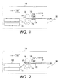
- a dual media printer 100 is provided with a housing that combines conventional print functionality with transient reusable print functionality using a common shared platform and components.
- the printer includes a print controller 110 that controls receipt of an input image file and printing of the image file by the printer.
- a first type media tray 120 houses media sheets of a first type, such as conventional inkjet paper sheets.
- a second media tray 125 houses sheets of a second, different type, such as transient media sheets that are erasable and reusable, such as photochromic paper.
- a feed path P leads from each tray and feeds media sheets from the respective trays to a common feed path region where the media sheet passes several print components on its way to an output tray 180.
- FIG. 1 shows feeding of a media sheet from the first tray 120 to the common feed path region
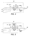
- FIG. 2 shows feeding of a media sheet from the second tray 125 to the common feed path region.
- Pre-conditioning station 135 is particularly useful to pre-condition transient media sheets that may have previously been used and contain a pre-existing image thereon.
- the pre-conditioning station 135 applies heat at a predetermined temperature for a given dwell time sufficient to erase the previous image from the media sheet, allowing the sheet to be reused and formed with a new image.
- the predetermined temperature may differ depending on the particular type of media sheet used, when photochromic paper is used as the media sheet, the temperature is generally in the range of about 120° or more, such as about 120°C to about 160° C.
- An increase in processing speed or transport rate may require higher temperatures to achieve a desired heating temperature to the media sheet. With a process speed of about 5 pages per minute, a temperature of approximately 160° has been found satisfactory.
- a conventional "instant-on" fuser roll found in low-end laser printers has been found satisfactory as a low-cost and efficient mechanism to achieve erase heating.
- An instant-on fuser roll has an internal quartz heater at the center of the roll to rapidly heat the outer surface of the fuser roll.
- other conventional and subsequently developed heating structures can be substituted.
- the drive roll 130 incrementally advances the media sheet by a print swath spacing between print swaths to locate the new region to be imaged under the traversing carriage assembly 140.
- the sheet media should either be wrapped over a portion of the heated fuser roll 135 forming the pre-conditioning station prior to the relatively narrow nip, or fuser roll 135 should have a nip that is as long or longer than the amount that the media sheet is advanced. Because the transient media sheet benefits most from the pre-conditioning, one way to achieve this is to have the transient media sheets fed from the lower tray 125.
- the two printheads 150, 160 are mounted to the same carriage assembly 140 and can beneficially be arranged side-by-side in a carriage movement direction C that is transverse to the feed path direction P of the sheet media.
- Image path electronics within controller 110 can then control imaging by each printhead from source data as the carriage assembly 140 traverses back and forth across the media sheet as is known in the art.
- inkjet printheads have a maintenance station that maintains operation of the various inkjet nozzles.
- Maintenance stations usually include an inkjet printhead cap that covers the nozzles during non-use to prevent excessive drying out of ink. These stations are often located at a park position of the carriage assembly near one end of travel and out of the printzone region opposing the media sheet.
- the inkjet and/or UV printheads may be selectively decoupled from the carriage assembly when not in use so that only one printhead travels with the carriage assembly at one time.
- the inkjet printhead could remain at the maintenance station during operation of the UV printhead.
- Transport of the media sheet past the printheads 150, 160 and to a printer output, such as output tray 180, may be assisted by additional drive mechanisms, such as pinch roll 175 driven by motor 115 downstream of the printheads.
- a printzone region traversed by the carriage assembly 140 and printheads 150, 160 includes a printzone conditioning station 170 that maintains the media sheet at a desired elevated temperature conducive to writing. This is particularly beneficial for transient media that rely on combinations of UV exposure and heat for imaging, such as certain photochromic paper formulations.
- the temperature is maintained to be above ambient, such as in a range of 40 - 90°C, or about 70°C.
- the printzone conditioning station 170 may be active or passive. If active, the printzone conditioning station 170 may be formed of a heated platen that is located under the printheads 150, 160 and extends generally the width of the printheads 150/160 in the feed direction as shown, and may form portions of the output tray 180 itself. The conditioning station 170 when active should not extend beyond the printzone. If passive, the printzone conditioning station 170 may be formed of an insulated platen with a low thermal conduction that controls the cooling rate of the media sheet so that it maintains a desired elevated temperature during printing thereon.
- the printzone conditioning station 170 is another shared component that is used by either imaging technology to allow the media sheet to be controlled at a desired temperature to attain necessary quality and consistency in the imaging process.
- the type of media sheet used may be user selected by setting of a desired operation mode or specified as part of the input image file in which case the selection may be automated based on specific image content.
- a temporary transient document such as for reviewing of a draft
- the user selects a transient document mode where the printer 100 feeds a media sheet from the transient media tray 125 and activates the pre-conditioning station 135 to heat ( FIG. 2 ).
- the media sheet is then advanced through the heated nip where any pre-existing image on the transient media sheet is erased.
- the heated media sheet is then advanced to a printzone where the media sheet is written upon with the UV LED printhead 160 shuttled on the common carriage assembly to form an image thereon based on a received input image file.
- the printzone conditioning station 170 maintains the desired elevated temperature of the media sheet during printing.
- the user selects an archival document mode where the printer 100 feeds a media sheet from the conventional media tray 120 through the nip and into the printzone, where it is written upon with the inkjet printhead 150 by shuttling of the common carriage assembly ( FIG. 1 ).
- one or both of the pre-conditioning station 135 and printzone conditioning station 170 may be activated to maintain the media sheet at an elevated temperature during printing to improve image quality.
- a sensor may be provided that detects loading of proper media sheet type in each tray.
- transient media sheets such as photochromic paper, are often of a non-white color due to the coating process, they can also be distinguished by color.
- the second embodiment of FIG. 4 is similar to that of FIGS. 1-2 , and provides a dual media type printer 200 having a common housing containing a controller 210, first media tray 220 that houses a first-type media sheet (such as conventional paper), second media tray 225 that houses a second-type media sheet (such as transient photochromic media), reciprocating carriage assembly 240 having an inkjet printhead 250 and UV printhead 260 mounted for movement thereon, printzone conditioning station 270, and output tray 280.
- the second embodiment differs from FIGS. 1-2 by using a pinch-roll type drive mechanism 295 instead of a drive roll, and upper and lower heated platens 230, 290 as the pre-conditioning station instead of a fuser roll.
- Pinch-roll type drive mechanisms are well known and can be configured such as that shown as element 175 in FIG. 3 with the pinch rolls located near outboard sides of the media and driven by a motor as in FIG. 3 .
- the use of upper and lower heated platens 230, 290 may provide reduced dwell time and can result in increased media feed rates due to the increased surface area opposed to the media sheet during feeding. This increased surface area can improve heating efficiencies allowing the media sheet to reach desired erase or pre-conditioning temperature conditions more readily.
- a first zone achieves pre-conditioning of the media sheet prior to imaging, and a second zone achieves conditioning of the media sheet during printing as shown.
- Vacuum hold-down 390 serves to advance the media sheet along the feed path while also urging the media sheet against the heated lower platen 330 to improve heating efficiency, allowing the media sheet to reach desired erase or pre-conditioning temperature conditions more readily.
- this embodiment provides a first zone that achieves pre-conditioning of the media sheet prior to imaging, and a second zone that achieves conditioning of the media sheet during printing as shown.
Description
- This disclosure is generally directed to a dual media type printer and method that is capable of printing with both conventional print technologies that apply marking material on conventional media and with inkless and tonerless print technologies on reimageable and reusable transient media, such as photochromic paper.
- Conventional printing by xerographic and inkjet print technologies is known. Inkjet printing has a well-established market and uses a relatively low-cost process, where images are formed by ejecting droplets of ink in an image-wise manner onto a substrate. Inkjet printers are widely used in home and business environments, and particularly in home environments due to the low cost of inkjet printers. Inkjet printers generally allow for producing high quality images, ranging from black-and-white text to photographic color images, on a wide range of substrates such as standard office paper, transparencies, and photographic paper.
- However, despite the low printer costs, the cost of replacement inkjet cartridges can be high, and sometimes higher than the cost of the printer itself over the life of the machine. These cartridges must be replaced frequently, and thus replacement costs of the ink cartridges are a primary consumer complaint relating to inkjet printing. Reducing ink cartridge replacement costs would thus be a significant enhancement to inkjet printing users.
- In addition, many paper documents are promptly discarded after being read. Although paper is relatively inexpensive, the quantity of discarded paper documents is enormous and the disposal of these discarded paper documents raises significant cost and environmental issues. Accordingly, there is a continuing desire to provide a new medium that can display a desired image temporarily, and methods for preparing and using such a medium.
- To address these problems, a number of transient media approaches have been developed for transient image formation and storage. These media are designed to replace conventional paper for some applications. However, many forms of transient media provide less than desirable results as a paper substitute. For example, alternative technologies with transient images include liquid crystal displays, electrophoretics, and gyricon image media. While these technologies do provide the desired reimageability, they do not provide a document that has the appearance, feel or portability of traditional paper, nor the low cost that allows users to feel comfortable occasionally losing sheets. More recently, transient document media have been developed having a more paper-like form, such as photochromic paper. Photochromic media is typically marked upon using ultraviolet (UV) light and typically erased with light and/or heat. The media or paper is designed so that it may be reused with different images rendered thereon, in order to replace paper printing in some applications.
- Imaging techniques employing photochromic materials, that is materials which undergo reversible or irreversible photoinduced color changes, are known. For example,
U.S. Patent No. 3,961,948 discloses an imaging method based upon visible light induced changes in a photochromic imaging layer containing a dispersion of at least one photochromic material in an organic film forming binder. Other known photochromic materials can be found in U.S. Patent Application Publication No.US2005/0244742 to Iftime et al. ; U.S. Patent Application Publication No.US2005/0244743 to Iftime et al. ; and U.S. Patent Application Publication No.US2005/0244744 to Kazmaier et al . - These and other photochromic (or reimageable) papers are desirable because they can provide imaging media that can be reused many times, to transiently display images and text. For example, applications for photochromic based media include reimageable documents such as, for example, paper versions of electronic documents. Reimageable documents allow information to be kept for as long as the user wants, then the information can be erased and the media can be re-imaged using an imaging system with different information.
- Transient document printers have been described, for example, in U.S. Patent Application Publication No.
US2008/0310869 to Iftime et al . and U.S. Patent Application Publication No.US2008/0191136 to Shrader et al .. - However, transient media systems often suffer from problems not faced by conventional print media, such as paper printed by a laser printer or ink jet printer. Transient media, particularly photochromic paper, has only limited document image life before the image fades or self-erases, typically on the order of several hours to a few days depending on conditions and media used, and may have a degraded appearance when exposed to elevated light or heat conditions once printed. Thus, transient document printers and photochromic papers cannot fully replace conventional printing where archival quality is sometimes needed. Moreover, transient media systems cannot operate with standard papers or standard print technologies. That is, a transient printer will not print on conventional paper because conventional paper does not have the photochromic materials required for image formation. Likewise, a conventional printer cannot print on photochromic paper, without ruining the reusability of the transient media by depositing permanent marking material on the media. Thus, when a consumer wants to use both types of media sheets, a separate stand-alone system for each type of print technology has been used.
-
US2009034997A discloses a printing system having both permanent and temporary writing sources for forming a combined image on an erasable substrate.US20080191136A discloses a printing device capable of printing both traditional document media and transient document media by inserting a temporary imaging unit within the paper path at the output of the printing system.JP2001334649A US5943067A discloses a single media tray inkjet printer that, in addition to a conventional inkjet cartridge for use with conventional print media, may also carry a reusable media cartridge effective to generate an erasable image on reusable print media. - Present invention provides a printer and a method according to
claims 1 and 11 that combine conventional print and reusable print media functionality in a shared stand-alone system. Such a system would allow a user flexibility in deciding whether to print a temporary document or an archival permanent document or combinations thereof. - In exemplary embodiments, the system and method integrate and share as much functionality as possible to reduce manufacturing and operating costs, as well as to reduce the device's footprint.
- The dual media printer and method feeds media from separate feed trays depending on media type so that both types of media sheets may be provided.
- To maintain low cost the disclosure uses a carriage that moves printheads for both media types with the same mechanism and in some aspects reuses image path electronics for both media types.
- In one aspect of described embodiments, a dual media type printer is provided that shares common functionality, including a common printhead shuttling mechanism (traversing carriage), paper feed path portions and drive mechanism.
- The dual media type printer also shares pre-conditioning and printzone conditioning stations to achieve precondition heating and/or erasing of media sheets prior to and during printing. This is because conventional ink jet printing can also benefit from heating of the paper as a way to promote ink drying.
- In accordance with one aspect of the disclosure, a dual media printer for use with conventional media sheets and transient, reusable media sheets, comprises:
- a first media tray configured for housing the conventional media sheets;
- a second media tray configured for housing the transient, reusable media sheets;
- a printer output;
- a feed path connecting each of the first media tray and second media tray with the printer output, the feed path including a common feed path portion;
- a drive assembly that selectively feeds the conventional media sheets and the transient, reusable media sheets from either the first media tray or the second media tray to the printer output along the feed path in a feed direction;
- a first printhead the first printhead depositing a marking material onto one of the conventional media sheets to form an image thereon; and
- a second printhead the second printhead irradiating a surface of one of the transient, reusable media sheets to form a transient image thereon;
- a pre-conditioning station located on the common feed path, the pre-conditioning station heating at least the transient, reusable media sheets to condition the sheets for printing,
- characterised by a reciprocating carriage assembly located on the feed path, wherein the first and second printheads are mounted to the carriage assembly for movement therewith transverse to the feed direction,
- the pre-conditioning station is located upstream of the reciprocating carriage assembly;
- the first printhead is an inkjet printhead; and
- a printzone conditioning station is located on the common feed path under the reciprocating carriage assembly, the printzone conditioning station maintaining an elevated temperature of at least the transient, reusable media sheets during printing of above ambient.
- In accordance with another aspect of the disclosure, a dual media printing method according to claim 11, for use with conventional media sheets and transient, reusable media sheets using a dual media printer, comprises:
- feeding either a conventional media sheet from a first media tray or a transient, reusable media sheet from a second mediatray onto a common feed path past a pre-conditioning station;
- conditioning the fed media sheet at the pre-conditioning station by heating to a desired temperature;
- operating a common reciprocating carriage assembly to form an image on the fed media sheet using one of a first, inkjet, printhead that applies a marking material onto the media sheet when the media sheet is a conventional media sheet and a second printhead that irradiates a surface of the media sheet when the media sheet is a transient, reusable media sheet;
- maintaining an elevated temperature of the media sheet during printing of above ambient at a printzone conditioning station located on the common feed path under the reciprocating carriage assembly; and
- outputting the media sheet with a formed image thereon.
- A further aspect of the described embodiments makes use of a conventional "instant on" heated roll similar to a fuser roll used in electrophotography as the pre-conditioning station to reduce manufacturing costs.
- In embodiments of the described embodiments, the dual media type printer may include a UV printhead, such as an LED printhead, as a transient media type printhead, and a conventional inkjet printhead that applies a marking material onto a media sheet as a differing type of printhead.
- In exemplary embodiments, the printzone conditioning station may be an active or a passive platen that controls the temperature of the media sheet during printing.
- In exemplary embodiments, for the case of transient media, the preconditioning station heats the print media sheet to a temperature of about 120° or more, such as in the range of about 120° to about 160°C, for erasure of any residual images, and the printzone conditioning station maintains a temperature of the media sheet above ambient during printing, such as at about 70°C.
- In exemplary embodiments, the pre-conditioning station may be in the form of one or more heated platens or strip heaters provided above and/or below the print media.
- In exemplary embodiments, the media sheets may be driven by a common drive mechanism in the form of a drive roll, pinch roll or vacuum hold-down belt.
-
-
FIGS. 1-2 are representative illustrations of a dual media type printer in accordance with a first embodiment that combines conventional print functionality with transient reusable print functionality using a common shared platform and components, withFIG. 1 showing a paper path for conventional media andFIG. 2 showing a paper path for transient media; -
FIG. 3 is a partial perspective view of main drive and print components within the printer housing ofFIGS. 1-2 ; -
FIG. 4 is a representative illustration of a dual media type printer in accordance with a second embodiment, in which upper and lower heating platens are used in place of a heated roll and a pinch-roll type drive mechanism is used; and -
FIG. 5 is a representative illustration of a dual media type printer in accordance with a third embodiment, in which a lower heating platen is used with a vacuum hold-down drive mechanism. - A first embodiment of the disclosure will be described with reference to
FIGS. 1-3 . Adual media printer 100 is provided with a housing that combines conventional print functionality with transient reusable print functionality using a common shared platform and components. The printer includes aprint controller 110 that controls receipt of an input image file and printing of the image file by the printer. A firsttype media tray 120 houses media sheets of a first type, such as conventional inkjet paper sheets. Asecond media tray 125 houses sheets of a second, different type, such as transient media sheets that are erasable and reusable, such as photochromic paper. A feed path P leads from each tray and feeds media sheets from the respective trays to a common feed path region where the media sheet passes several print components on its way to anoutput tray 180.FIG. 1 shows feeding of a media sheet from thefirst tray 120 to the common feed path region andFIG. 2 shows feeding of a media sheet from thesecond tray 125 to the common feed path region. - In this embodiment, a drive mechanism is formed by the combination of a
drive roll 130 and aheated roll 135 that form a nip region therebetween. The drive mechanism advances the media sheet to a downstream common printhead shuttling mechanism in the form of a traversingcarriage assembly 140 that contains a printhead for each of two different print technologies. In this exemplary embodiment, a first printhead is aninkjet printhead 150 that dispenses droplets of ink to form an image and a second printhead is a transient media writing device, such as aUV printhead 160 formed of a plurality of LEDs, that emit UV light that reacts with transient media sheets, such as photochromic paper, to form a temporary image thereon. Theheated roll 135 also serves as a pre-conditioning station that conditions the media sheet prior to printing. -
Pre-conditioning station 135 is particularly useful to pre-condition transient media sheets that may have previously been used and contain a pre-existing image thereon. Thepre-conditioning station 135 applies heat at a predetermined temperature for a given dwell time sufficient to erase the previous image from the media sheet, allowing the sheet to be reused and formed with a new image. Although the predetermined temperature may differ depending on the particular type of media sheet used, when photochromic paper is used as the media sheet, the temperature is generally in the range of about 120° or more, such as about 120°C to about 160° C. An increase in processing speed or transport rate may require higher temperatures to achieve a desired heating temperature to the media sheet. With a process speed of about 5 pages per minute, a temperature of approximately 160° has been found satisfactory. - In this embodiment, a conventional "instant-on" fuser roll found in low-end laser printers has been found satisfactory as a low-cost and efficient mechanism to achieve erase heating. An instant-on fuser roll has an internal quartz heater at the center of the roll to rapidly heat the outer surface of the fuser roll. However, other conventional and subsequently developed heating structures can be substituted.
- The
drive roll 130 incrementally advances the media sheet by a print swath spacing between print swaths to locate the new region to be imaged under the traversingcarriage assembly 140. In order to have the media sheet dwell at a desired elevated temperature needed for erasure, and given that the drive speed is preferably rapid during paper advance to improve throughput, the sheet media should either be wrapped over a portion of theheated fuser roll 135 forming the pre-conditioning station prior to the relatively narrow nip, orfuser roll 135 should have a nip that is as long or longer than the amount that the media sheet is advanced. Because the transient media sheet benefits most from the pre-conditioning, one way to achieve this is to have the transient media sheets fed from thelower tray 125. The feed path for this media can be made to pass across an arc of theheated roll 135 to increase the contact area, and thus improve thermal transfer and increase dwell time, as shown inFIG. 2 . Alternatively, other pre-conditioning station components could be used instead of the fuser roll, such as platen heaters provided above and/or below the media sheet as discussed in another embodiment. Other heating methods can also be used. - As better shown in
FIG. 3 , the twoprintheads same carriage assembly 140 and can beneficially be arranged side-by-side in a carriage movement direction C that is transverse to the feed path direction P of the sheet media. Image path electronics withincontroller 110 can then control imaging by each printhead from source data as thecarriage assembly 140 traverses back and forth across the media sheet as is known in the art. - Back and forth shuttling are achieved, by a
carriage assembly 140 containing for example acartridge housing 142 that fixedly receives theinkjet printhead 150 andUV printhead 160.Housing 142 is laterally guided byguide bar 144 and moved by adrive mechanism 146, such as a cable driven by a motor (unshown) as is known in the art, or driven by a lead screw (unshown). - Typically, inkjet printheads have a maintenance station that maintains operation of the various inkjet nozzles. Maintenance stations usually include an inkjet printhead cap that covers the nozzles during non-use to prevent excessive drying out of ink. These stations are often located at a park position of the carriage assembly near one end of travel and out of the printzone region opposing the media sheet. However, because operation of the
UV printhead 160 during non-use of theinkjet printhead 150 will prevent return to the park position for extended periods of time, it may be desirable to add a positionable maintenance cap directly to the inkjet printhead. This will allow capping of theinkjet printhead 150 even during periods of travel. Alternatively, the inkjet and/or UV printheads may be selectively decoupled from the carriage assembly when not in use so that only one printhead travels with the carriage assembly at one time. For example, with this, the inkjet printhead could remain at the maintenance station during operation of the UV printhead. - Transport of the media sheet past the
printheads output tray 180, may be assisted by additional drive mechanisms, such aspinch roll 175 driven bymotor 115 downstream of the printheads. - A printzone region traversed by the
carriage assembly 140 andprintheads printzone conditioning station 170 that maintains the media sheet at a desired elevated temperature conducive to writing. This is particularly beneficial for transient media that rely on combinations of UV exposure and heat for imaging, such as certain photochromic paper formulations. - In exemplary embodiments, the temperature is maintained to be above ambient, such as in a range of 40 - 90°C, or about 70°C. In exemplary embodiments, the
printzone conditioning station 170 may be active or passive. If active, theprintzone conditioning station 170 may be formed of a heated platen that is located under theprintheads printheads 150/160 in the feed direction as shown, and may form portions of theoutput tray 180 itself. Theconditioning station 170 when active should not extend beyond the printzone. If passive, theprintzone conditioning station 170 may be formed of an insulated platen with a low thermal conduction that controls the cooling rate of the media sheet so that it maintains a desired elevated temperature during printing thereon. Because aqueous ink printing systems such as inkjet printing also have been shown to have improved image quality when the media has been heated, theprintzone conditioning station 170 is another shared component that is used by either imaging technology to allow the media sheet to be controlled at a desired temperature to attain necessary quality and consistency in the imaging process. - With this
dual media printer 100, a user is able to readily print on either of two media sheet types using two different imaging technologies. In exemplary embodiments, the type of media sheet used may be user selected by setting of a desired operation mode or specified as part of the input image file in which case the selection may be automated based on specific image content. When a temporary transient document is desired, such as for reviewing of a draft, the user selects a transient document mode where theprinter 100 feeds a media sheet from thetransient media tray 125 and activates thepre-conditioning station 135 to heat (FIG. 2 ). The media sheet is then advanced through the heated nip where any pre-existing image on the transient media sheet is erased. The heated media sheet is then advanced to a printzone where the media sheet is written upon with theUV LED printhead 160 shuttled on the common carriage assembly to form an image thereon based on a received input image file. Theprintzone conditioning station 170 maintains the desired elevated temperature of the media sheet during printing. Similarly, when an archival document is desired, the user selects an archival document mode where theprinter 100 feeds a media sheet from theconventional media tray 120 through the nip and into the printzone, where it is written upon with theinkjet printhead 150 by shuttling of the common carriage assembly (FIG. 1 ). As with the transient document, one or both of thepre-conditioning station 135 andprintzone conditioning station 170 may be activated to maintain the media sheet at an elevated temperature during printing to improve image quality. To ensure proper operation, a sensor may be provided that detects loading of proper media sheet type in each tray. Alternatively, because transient media sheets, such as photochromic paper, are often of a non-white color due to the coating process, they can also be distinguished by color. - The second embodiment of
FIG. 4 is similar to that ofFIGS. 1-2 , and provides a dualmedia type printer 200 having a common housing containing acontroller 210,first media tray 220 that houses a first-type media sheet (such as conventional paper),second media tray 225 that houses a second-type media sheet (such as transient photochromic media), reciprocatingcarriage assembly 240 having an inkjet printhead 250 and UV printhead 260 mounted for movement thereon,printzone conditioning station 270, andoutput tray 280. The second embodiment differs fromFIGS. 1-2 by using a pinch-rolltype drive mechanism 295 instead of a drive roll, and upper and lowerheated platens element 175 inFIG. 3 with the pinch rolls located near outboard sides of the media and driven by a motor as inFIG. 3 . The use of upper and lowerheated platens - The third embodiment of
FIG. 5 is similar to that ofFIG. 4 , and provides a dualmedia type printer 300 having a common housing containing acontroller 310,first media tray 320 that houses a first-type media sheet (such as conventional paper),second media tray 325 that houses a second-type media sheet (such as transient photochromic media), reciprocatingcarriage assembly 340 having an inkjet printhead 350 and UV printhead 360 mounted for movement thereon, printzone conditioning station 370, andoutput tray 380. The third embodiment also uses a heatedlower platen 330 as the pre-conditioning station instead of a heated roll. However, to provide drive force and to improve thermal efficiency, this embodiment uses a vacuum hold-down 390. Vacuum hold-down 390 serves to advance the media sheet along the feed path while also urging the media sheet against the heatedlower platen 330 to improve heating efficiency, allowing the media sheet to reach desired erase or pre-conditioning temperature conditions more readily. As in theFIG. 4 embodiment, this embodiment provides a first zone that achieves pre-conditioning of the media sheet prior to imaging, and a second zone that achieves conditioning of the media sheet during printing as shown.
Claims (19)
- A dual media printer (100) for use with conventional media sheets and transient, reusable media sheets, comprising:a first media tray (120) configured for housing the conventional media sheets;a second media tray (125) configured for housing the transient, reusable media sheets;a printer output (180);a feed path (P) connecting each of the first media tray and second media tray with the printer output, the feed path including a common feed path portion;a drive assembly (115, 130, 135, 175; 295; 390) that selectively feeds the conventional media sheets and the transient, reusable media sheets from either the first media tray or the second media tray to the printer output along the feed path in a feed direction;a first printhead (150; 250; 350) the first printhead depositing a marking material onto one of the conventional media sheets to form an image thereon; anda second printhead (160; 260; 360) the second printhead irradiating a surface of one of the transient, reusable media sheets to form a transient image thereon;a pre-conditioning station (135; 230, 290; 330) located on the common feed path, the pre-conditioning station heating at least the transient, reusable media sheets to condition the sheets for printing,characterised by a reciprocating carriage assembly (140) located on the feed path, wherein the first and second printheads are mounted to the carriage assembly for movement therewith transverse to the feed direction,the pre-conditioning station is located upstream of the reciprocating carriage assembly;the first printhead is an inkjet printhead; anda printzone conditioning station (170; 270) is located on the common feed path under the reciprocating carriage assembly (140), the printzone conditioning station maintaining an elevated temperature of at least the transient, reusable media sheets during printing of above ambient.
- The dual media printer (100) according to claim 1, wherein the pre-conditioning station (135; 230, 290; 330) is heated to a temperature, between 120° to 160° C, for a given dwell time.
- The dual media printer (100) according to claim 2, wherein the pre-conditioning station (135) is an instant on heated roll.
- The dual media printer (100) according to any of the preceding claims, wherein for transient, reusable media sheets, the printzone conditioning station (170; 270) maintains an elevated temperature during printing in the range of 40 - 90°C.
- The dual media printer (100) according to any of the preceding claims, wherein the printzone conditioning station (170; 270) passively maintains the elevated temperature imposed by the pre-conditioning station (135; 230, 290; 330) by insulating fed ones of the conventional media sheets or transient, reusable media sheets from excessive heat loss as the fed ones are held stationary under the reciprocating carriage assembly during printhead writing.
- A dual media printer (100) according to any of the preceding claims, wherein the second printhead is a UV printhead (160; 260; 360).
- A dual media printer (100) according to any of the preceding claims, wherein the feed path is configured to provide a greater pre-conditioning station contact area to transient, reusable media sheets than to conventional media sheets.
- A dual media printer (100) according to claim 7, wherein the pre-conditioning station is a heated roll (135) having a circumference and the greater contact area is achieved by wrapping the transient, reusable media sheet around a different fraction of the circumference.
- A dual media printer according to any of the preceding claims further comprising a positionable maintenance cap disposed on the first printhead for selectively capping the inkhead.
- A dual media printer according to any of claims 1 to 9 further comprising means for selectively decoupling the first printhead from the reciprocating carriage assembly when the first printhead is not in use.
- A dual media printing method for use with conventional media sheets and transient, reusable media sheets using a dual media printer (100), the method comprising:feeding either a conventional media sheet from a first media tray or a transient, reusable media sheet from a second media tray onto a common feed path past a pre-conditioning station (135; 230, 290; 330);conditioning the fed media sheet at the pre-conditioning station by heating to a desired temperature;operating a common reciprocating carriage assembly (140) to form an image on the fed media sheet using one of a first, inkjet, printhead (150; 250; 350) that applies a marking material onto the media sheet when the media sheet is a conventional media sheet and a second printhead (160; 260; 360) that irradiates a surface of the media sheet when the media sheet is a transient, reusable media sheet;maintaining an elevated temperature of the media sheet during printing of above ambient at a printzone conditioning station (170; 270) located on the common feed path under the reciprocating carriage assembly; andoutputting the media sheet with a formed image thereon.
- The method according to claim 11, wherein the pre-conditioning station (135; 230, 290; 330) is heated to a temperature for a dwell time sufficient to erase previous images on the media sheet prior to printing by the second printhead (160; 260; 360) when the media sheet is a transient, reusable media sheet.
- The method according to claim 12, wherein the temperature is between 120° to 160° C.
- The method according to any of claims 11 to 13, wherein for transient, reusable media, the elevated temperature of the media sheet during printing is in the range of 40-90°C.
- The method according to any of claims 11 to 14, wherein the elevated temperature in the printzone is achieved by active heat from the pre-conditioning station (135; 230, 290; 330) and passive insulation of the media sheet from heat loss as it is held stationary under the reciprocating carriage mechanism (140) during printhead writing.
- The method according to any of claims 11 to 15, further comprising providing a greater contact area of the pre-conditioning station (135; 230, 290; 330) to transient, reusable media sheets than to conventional media sheets during the feeding.
- The method according to claim 16, wherein the pre-conditioning station is a heated roll (135) having a circumference and the greater contact area is achieved by wrapping the transient, reusable media sheet around a different fraction of the circumference.
- The method according to any of claims 11 to 17, wherein the first printhead (150) is capped by a positionable maintenance cap disposed on the first printhead when not in use.
- The method according to any of claims 11 to 17 wherein the first printhead (150) is selectively decoupled from the reciprocating carriage assembly when not in use.
Applications Claiming Priority (1)
| Application Number | Priority Date | Filing Date | Title |
|---|---|---|---|
| US12/400,148 US8113646B2 (en) | 2009-03-09 | 2009-03-09 | Combined inkjet and photochromic reusable paper personal printer |
Publications (2)
| Publication Number | Publication Date |
|---|---|
| EP2228221A1 EP2228221A1 (en) | 2010-09-15 |
| EP2228221B1 true EP2228221B1 (en) | 2012-05-16 |
Family
ID=42162078
Family Applications (1)
| Application Number | Title | Priority Date | Filing Date |
|---|---|---|---|
| EP10155449A Not-in-force EP2228221B1 (en) | 2009-03-09 | 2010-03-04 | Printer for inkjet and for printing on photochromic reusable paper |
Country Status (6)
| Country | Link |
|---|---|
| US (1) | US8113646B2 (en) |
| EP (1) | EP2228221B1 (en) |
| JP (1) | JP5469485B2 (en) |
| KR (1) | KR101581473B1 (en) |
| CN (1) | CN101837678B (en) |
| CA (1) | CA2695107C (en) |
Families Citing this family (19)
| Publication number | Priority date | Publication date | Assignee | Title |
|---|---|---|---|---|
| US8915583B2 (en) * | 2008-05-27 | 2014-12-23 | Avery Dennison Corporation | Systems, methods, and materials for temporary printing and indicia |
| US7935463B2 (en) * | 2009-03-09 | 2011-05-03 | Xerox Corporation | Reusable paper media with compatibility markings and printer with incompatible media sensor |
| JP5378865B2 (en) * | 2009-04-14 | 2013-12-25 | 株式会社沖データ | Image forming apparatus |
| US8177347B2 (en) | 2009-07-16 | 2012-05-15 | Xerox Corporation | Dual mode printer |
| US8132884B2 (en) | 2009-08-17 | 2012-03-13 | Xerox Corporation | Dual mode printer write heads |
| US8358323B2 (en) * | 2009-08-17 | 2013-01-22 | Xerox Corporation | Write heating architecture for dual mode imaging systems |
| US8130249B2 (en) * | 2009-08-17 | 2012-03-06 | Xerox Corporation | Erase decoupled from writing for erasable paper |
| JP5741802B2 (en) * | 2010-12-24 | 2015-07-01 | セイコーエプソン株式会社 | Recording device |
| JP5834557B2 (en) * | 2011-07-08 | 2015-12-24 | セイコーエプソン株式会社 | Recording device |
| CN102642403B (en) * | 2012-05-08 | 2014-07-23 | 珠海天威飞马打印耗材有限公司 | Ink-jet printer |
| JP6270311B2 (en) * | 2012-09-28 | 2018-01-31 | 株式会社ミマキエンジニアリング | Printing device |
| JP2014148132A (en) * | 2013-02-01 | 2014-08-21 | Mimaki Engineering Co Ltd | Ink jet recorder and recording method |
| JP6311412B2 (en) | 2013-12-27 | 2018-04-18 | セイコーエプソン株式会社 | Liquid ejection device |
| JP6454996B2 (en) | 2014-07-01 | 2019-01-23 | セイコーエプソン株式会社 | Liquid ejection device |
| WO2017134955A1 (en) * | 2016-02-04 | 2017-08-10 | 株式会社ミマキエンジニアリング | Printing device and printing method |
| JP6922285B2 (en) * | 2016-05-06 | 2021-08-18 | 株式会社リコー | Image addition system, printing device, fabric holding member, holding member with cloth |
| US20210323326A1 (en) * | 2018-09-14 | 2021-10-21 | Hewlett-Packard Development Company, L.P. | Printer carriages |
| WO2020117241A1 (en) * | 2018-12-06 | 2020-06-11 | Hewlett-Packard Development Company, L.P. | Print media modes |
| CN110744930A (en) * | 2019-11-12 | 2020-02-04 | 联想万像(深圳)科技有限公司 | Laser and ink jet integrated machine |
Family Cites Families (35)
| Publication number | Priority date | Publication date | Assignee | Title |
|---|---|---|---|---|
| US3961948A (en) * | 1974-01-15 | 1976-06-08 | Xerox Corporation | Photochromic imaging method |
| US4413266A (en) * | 1981-12-14 | 1983-11-01 | International Business Machines Corporation | Method and apparatus for erasing ink jet printing |
| JPH01174492A (en) * | 1987-09-11 | 1989-07-11 | Casio Comput Co Ltd | Information card and manufacturing device thereof |
| JPH0761146A (en) * | 1993-08-27 | 1995-03-07 | Toshiba Corp | Record medium and image recording method |
| JP2907696B2 (en) * | 1993-10-21 | 1999-06-21 | キヤノン株式会社 | Image forming device |
| US6000870A (en) * | 1996-10-14 | 1999-12-14 | Brother Kogyo Kabushiki Kaisha | Printing device having dual sheet feed trays |
| KR100224600B1 (en) * | 1996-10-21 | 1999-10-15 | 윤종용 | Multi functional dempheral product having long type lamp |
| US5943067A (en) * | 1997-04-28 | 1999-08-24 | Hewlett-Packard Company | Reusable media inkjet printing system |
| JPH1134412A (en) * | 1997-07-17 | 1999-02-09 | Brother Ind Ltd | Printing apparatus |
| US5790915A (en) * | 1997-10-09 | 1998-08-04 | Hewlett-Packard Company | Plane registration for monochrome and color printing systems |
| US6293668B1 (en) * | 1998-04-29 | 2001-09-25 | Xerox Corporation | Method and apparatus for treating recording media to enhance print quality in an ink jet printer |
| US6276792B1 (en) * | 1999-03-31 | 2001-08-21 | Xerox Corporation | Color printing apparatus and processes thereof |
| JP2001005318A (en) * | 1999-06-18 | 2001-01-12 | Sharp Corp | Image forming device |
| JP3980247B2 (en) * | 2000-04-25 | 2007-09-26 | 株式会社リコー | Colorless ink and ink jet printer using the same |
| JP2001315368A (en) * | 2000-05-11 | 2001-11-13 | Minolta Co Ltd | Image-forming apparatus |
| JP2001334649A (en) | 2000-05-26 | 2001-12-04 | Minolta Co Ltd | Imaging apparatus for outputting on both general sheet and reusable sheet |
| US6582039B2 (en) * | 2001-07-24 | 2003-06-24 | Hewlett-Packard Developement Company, L.P. | Combination color inkjet and laser image-printing device with dual paper-picking mechanism and method of implementing same |
| JP2003182106A (en) * | 2001-10-12 | 2003-07-03 | Ricoh Co Ltd | Color ink jet recorder |
| US6825864B2 (en) * | 2001-11-26 | 2004-11-30 | Codonics, Inc. | Multi-media printer |
| CA2519790C (en) * | 2003-04-18 | 2011-05-03 | Mimaki Engineering Co., Ltd. | Inkjet printer |
| US7332257B2 (en) * | 2003-07-11 | 2008-02-19 | Asahi Glass Company, Limited | Composition for optical film, and optical film |
| JP4063755B2 (en) * | 2003-10-21 | 2008-03-19 | 株式会社リコー | Image formation removal system |
| US7483046B2 (en) * | 2003-11-17 | 2009-01-27 | Samsung Electronics, Co., Ltd. | Complex image forming apparatus |
| US7300727B2 (en) * | 2004-04-29 | 2007-11-27 | Xerox Corporation | Method for forming temporary image |
| US7205088B2 (en) * | 2004-04-29 | 2007-04-17 | Xerox Corporation | Reimageable medium with light absorbing material |
| US7214456B2 (en) * | 2004-04-29 | 2007-05-08 | Xerox Corporation | Reimageable medium |
| US7694950B2 (en) | 2005-03-30 | 2010-04-13 | Brother Kogyo Kabushiki Kaisha | Sheet feed device and image recording apparatus having such sheet feed device |
| JP2006347049A (en) * | 2005-06-17 | 2006-12-28 | Kyocera Mita Corp | Printing-out apparatus with rewritable function |
| JP2007154087A (en) * | 2005-12-07 | 2007-06-21 | Konica Minolta Holdings Inc | Inkjet ink, ink set for inkjet ink and inkjet-recording method |
| US7488132B2 (en) * | 2005-12-21 | 2009-02-10 | Palo Alto Research Center Incorporated | Portable marking device for use with transient document media |
| WO2007139942A2 (en) * | 2006-05-26 | 2007-12-06 | Zink Imaging, Llc | Nonrotating platen for thermal printing |
| US7564030B2 (en) * | 2007-02-13 | 2009-07-21 | Palo Alto Research Center Incorporated | Method and system for forming temporary images |
| US7852366B2 (en) * | 2007-06-13 | 2010-12-14 | Xerox Corporation | System and method for printing reimageable transient documents |
| JP2009033632A (en) * | 2007-07-30 | 2009-02-12 | Nec Corp | Wimax system, radio terminal, and radio base station |
| US7992959B2 (en) | 2007-07-30 | 2011-08-09 | Lexmark International, Inc. | Printing system with transient and permanent imaging means |
-
2009
- 2009-03-09 US US12/400,148 patent/US8113646B2/en not_active Expired - Fee Related
-
2010
- 2010-03-02 CA CA2695107A patent/CA2695107C/en not_active Expired - Fee Related
- 2010-03-04 KR KR1020100019382A patent/KR101581473B1/en not_active IP Right Cessation
- 2010-03-04 EP EP10155449A patent/EP2228221B1/en not_active Not-in-force
- 2010-03-05 JP JP2010048498A patent/JP5469485B2/en not_active Expired - Fee Related
- 2010-03-09 CN CN201010142493.4A patent/CN101837678B/en not_active Expired - Fee Related
Also Published As
| Publication number | Publication date |
|---|---|
| JP5469485B2 (en) | 2014-04-16 |
| KR20100101525A (en) | 2010-09-17 |
| JP2010208325A (en) | 2010-09-24 |
| CA2695107A1 (en) | 2010-09-09 |
| EP2228221A1 (en) | 2010-09-15 |
| US8113646B2 (en) | 2012-02-14 |
| US20100225722A1 (en) | 2010-09-09 |
| CA2695107C (en) | 2012-05-08 |
| KR101581473B1 (en) | 2015-12-30 |
| CN101837678A (en) | 2010-09-22 |
| CN101837678B (en) | 2014-08-27 |
Similar Documents
| Publication | Publication Date | Title |
|---|---|---|
| EP2228221B1 (en) | Printer for inkjet and for printing on photochromic reusable paper | |
| US6639527B2 (en) | Inkjet printing system with an intermediate transfer member between the print engine and print medium | |
| JP2007196454A (en) | Thermal printer and printing method of thermal printer | |
| CN102431310A (en) | Image forming apparatus, image forming method, and program | |
| EP2287004B1 (en) | Dual mode printer write heads | |
| US20080216688A1 (en) | Inverted Reverse-Image Transfer Printing | |
| JPH11320867A (en) | Method for printing image and ink-jet printer | |
| EP2287003B1 (en) | Dual imaging of erasable and non-erasable media | |
| JP4403891B2 (en) | Printer | |
| JP4874556B2 (en) | Intermediate transfer type thermal transfer printer | |
| US20080219735A1 (en) | Printhead Assembly for a Credential Production Device | |
| US7508404B2 (en) | Thermal printer with two print heads | |
| US5954440A (en) | Thermal printer with sheet pressure means | |
| EP1504924A2 (en) | Scratch card printer and method of printing information on a scratch card | |
| CN109070600B (en) | Thermal transfer printer and control method thereof | |
| JPH0647966A (en) | Recording apparatus | |
| JP2000127532A (en) | Recording apparatus | |
| JPH07177325A (en) | Recorder | |
| JP2008302522A (en) | Image forming apparatus | |
| JP2008302515A (en) | Image forming method, image forming apparatus, ink ribbon, program, and recording medium with the program recorded | |
| JP2010023409A (en) | Recording device | |
| JP2007076054A (en) | Passbook forming device | |
| JP2000302286A (en) | Sheet guide and image forming device provided therewith | |
| KR20050034522A (en) | Thermal type image forming apparatus and method thereof | |
| JP2005238782A (en) | Intermediate transfer type thermal transfer printer |
Legal Events
| Date | Code | Title | Description |
|---|---|---|---|
| PUAI | Public reference made under article 153(3) epc to a published international application that has entered the european phase |
Free format text: ORIGINAL CODE: 0009012 |
|
| AK | Designated contracting states |
Kind code of ref document: A1 Designated state(s): AT BE BG CH CY CZ DE DK EE ES FI FR GB GR HR HU IE IS IT LI LT LU LV MC MK MT NL NO PL PT RO SE SI SK SM TR |
|
| 17P | Request for examination filed |
Effective date: 20110315 |
|
| GRAP | Despatch of communication of intention to grant a patent |
Free format text: ORIGINAL CODE: EPIDOSNIGR1 |
|
| RTI1 | Title (correction) |
Free format text: PRINTER FOR INKJET AND FOR PRINTING ON PHOTOCHROMIC REUSABLE PAPER |
|
| GRAS | Grant fee paid |
Free format text: ORIGINAL CODE: EPIDOSNIGR3 |
|
| GRAA | (expected) grant |
Free format text: ORIGINAL CODE: 0009210 |
|
| AK | Designated contracting states |
Kind code of ref document: B1 Designated state(s): AT BE BG CH CY CZ DE DK EE ES FI FR GB GR HR HU IE IS IT LI LT LU LV MC MK MT NL NO PL PT RO SE SI SK SM TR |
|
| REG | Reference to a national code |
Ref country code: GB Ref legal event code: FG4D |
|
| REG | Reference to a national code |
Ref country code: CH Ref legal event code: EP |
|
| REG | Reference to a national code |
Ref country code: AT Ref legal event code: REF Ref document number: 557893 Country of ref document: AT Kind code of ref document: T Effective date: 20120615 |
|
| REG | Reference to a national code |
Ref country code: IE Ref legal event code: FG4D |
|
| REG | Reference to a national code |
Ref country code: DE Ref legal event code: R096 Ref document number: 602010001556 Country of ref document: DE Effective date: 20120712 |
|
| REG | Reference to a national code |
Ref country code: NL Ref legal event code: VDEP Effective date: 20120516 |
|
| REG | Reference to a national code |
Ref country code: LT Ref legal event code: MG4D Effective date: 20120516 |
|
| PG25 | Lapsed in a contracting state [announced via postgrant information from national office to epo] |
Ref country code: FI Free format text: LAPSE BECAUSE OF FAILURE TO SUBMIT A TRANSLATION OF THE DESCRIPTION OR TO PAY THE FEE WITHIN THE PRESCRIBED TIME-LIMIT Effective date: 20120516 Ref country code: SE Free format text: LAPSE BECAUSE OF FAILURE TO SUBMIT A TRANSLATION OF THE DESCRIPTION OR TO PAY THE FEE WITHIN THE PRESCRIBED TIME-LIMIT Effective date: 20120516 Ref country code: LT Free format text: LAPSE BECAUSE OF FAILURE TO SUBMIT A TRANSLATION OF THE DESCRIPTION OR TO PAY THE FEE WITHIN THE PRESCRIBED TIME-LIMIT Effective date: 20120516 Ref country code: NO Free format text: LAPSE BECAUSE OF FAILURE TO SUBMIT A TRANSLATION OF THE DESCRIPTION OR TO PAY THE FEE WITHIN THE PRESCRIBED TIME-LIMIT Effective date: 20120816 Ref country code: IS Free format text: LAPSE BECAUSE OF FAILURE TO SUBMIT A TRANSLATION OF THE DESCRIPTION OR TO PAY THE FEE WITHIN THE PRESCRIBED TIME-LIMIT Effective date: 20120916 Ref country code: CY Free format text: LAPSE BECAUSE OF FAILURE TO SUBMIT A TRANSLATION OF THE DESCRIPTION OR TO PAY THE FEE WITHIN THE PRESCRIBED TIME-LIMIT Effective date: 20120516 Ref country code: PL Free format text: LAPSE BECAUSE OF FAILURE TO SUBMIT A TRANSLATION OF THE DESCRIPTION OR TO PAY THE FEE WITHIN THE PRESCRIBED TIME-LIMIT Effective date: 20120516 |
|
| REG | Reference to a national code |
Ref country code: AT Ref legal event code: MK05 Ref document number: 557893 Country of ref document: AT Kind code of ref document: T Effective date: 20120516 |
|
| PG25 | Lapsed in a contracting state [announced via postgrant information from national office to epo] |
Ref country code: GR Free format text: LAPSE BECAUSE OF FAILURE TO SUBMIT A TRANSLATION OF THE DESCRIPTION OR TO PAY THE FEE WITHIN THE PRESCRIBED TIME-LIMIT Effective date: 20120817 Ref country code: PT Free format text: LAPSE BECAUSE OF FAILURE TO SUBMIT A TRANSLATION OF THE DESCRIPTION OR TO PAY THE FEE WITHIN THE PRESCRIBED TIME-LIMIT Effective date: 20120917 Ref country code: HR Free format text: LAPSE BECAUSE OF FAILURE TO SUBMIT A TRANSLATION OF THE DESCRIPTION OR TO PAY THE FEE WITHIN THE PRESCRIBED TIME-LIMIT Effective date: 20120516 Ref country code: SI Free format text: LAPSE BECAUSE OF FAILURE TO SUBMIT A TRANSLATION OF THE DESCRIPTION OR TO PAY THE FEE WITHIN THE PRESCRIBED TIME-LIMIT Effective date: 20120516 Ref country code: LV Free format text: LAPSE BECAUSE OF FAILURE TO SUBMIT A TRANSLATION OF THE DESCRIPTION OR TO PAY THE FEE WITHIN THE PRESCRIBED TIME-LIMIT Effective date: 20120516 |
|
| PG25 | Lapsed in a contracting state [announced via postgrant information from national office to epo] |
Ref country code: BE Free format text: LAPSE BECAUSE OF FAILURE TO SUBMIT A TRANSLATION OF THE DESCRIPTION OR TO PAY THE FEE WITHIN THE PRESCRIBED TIME-LIMIT Effective date: 20120516 |
|
| PG25 | Lapsed in a contracting state [announced via postgrant information from national office to epo] |
Ref country code: RO Free format text: LAPSE BECAUSE OF FAILURE TO SUBMIT A TRANSLATION OF THE DESCRIPTION OR TO PAY THE FEE WITHIN THE PRESCRIBED TIME-LIMIT Effective date: 20120516 Ref country code: EE Free format text: LAPSE BECAUSE OF FAILURE TO SUBMIT A TRANSLATION OF THE DESCRIPTION OR TO PAY THE FEE WITHIN THE PRESCRIBED TIME-LIMIT Effective date: 20120516 Ref country code: AT Free format text: LAPSE BECAUSE OF FAILURE TO SUBMIT A TRANSLATION OF THE DESCRIPTION OR TO PAY THE FEE WITHIN THE PRESCRIBED TIME-LIMIT Effective date: 20120516 Ref country code: SK Free format text: LAPSE BECAUSE OF FAILURE TO SUBMIT A TRANSLATION OF THE DESCRIPTION OR TO PAY THE FEE WITHIN THE PRESCRIBED TIME-LIMIT Effective date: 20120516 Ref country code: DK Free format text: LAPSE BECAUSE OF FAILURE TO SUBMIT A TRANSLATION OF THE DESCRIPTION OR TO PAY THE FEE WITHIN THE PRESCRIBED TIME-LIMIT Effective date: 20120516 Ref country code: CZ Free format text: LAPSE BECAUSE OF FAILURE TO SUBMIT A TRANSLATION OF THE DESCRIPTION OR TO PAY THE FEE WITHIN THE PRESCRIBED TIME-LIMIT Effective date: 20120516 Ref country code: NL Free format text: LAPSE BECAUSE OF FAILURE TO SUBMIT A TRANSLATION OF THE DESCRIPTION OR TO PAY THE FEE WITHIN THE PRESCRIBED TIME-LIMIT Effective date: 20120516 |
|
| PG25 | Lapsed in a contracting state [announced via postgrant information from national office to epo] |
Ref country code: IT Free format text: LAPSE BECAUSE OF FAILURE TO SUBMIT A TRANSLATION OF THE DESCRIPTION OR TO PAY THE FEE WITHIN THE PRESCRIBED TIME-LIMIT Effective date: 20120516 |
|
| PLBE | No opposition filed within time limit |
Free format text: ORIGINAL CODE: 0009261 |
|
| STAA | Information on the status of an ep patent application or granted ep patent |
Free format text: STATUS: NO OPPOSITION FILED WITHIN TIME LIMIT |
|
| 26N | No opposition filed |
Effective date: 20130219 |
|
| REG | Reference to a national code |
Ref country code: DE Ref legal event code: R097 Ref document number: 602010001556 Country of ref document: DE Effective date: 20130219 |
|
| PG25 | Lapsed in a contracting state [announced via postgrant information from national office to epo] |
Ref country code: BG Free format text: LAPSE BECAUSE OF FAILURE TO SUBMIT A TRANSLATION OF THE DESCRIPTION OR TO PAY THE FEE WITHIN THE PRESCRIBED TIME-LIMIT Effective date: 20120816 |
|
| PG25 | Lapsed in a contracting state [announced via postgrant information from national office to epo] |
Ref country code: ES Free format text: LAPSE BECAUSE OF FAILURE TO SUBMIT A TRANSLATION OF THE DESCRIPTION OR TO PAY THE FEE WITHIN THE PRESCRIBED TIME-LIMIT Effective date: 20120827 Ref country code: MC Free format text: LAPSE BECAUSE OF NON-PAYMENT OF DUE FEES Effective date: 20130331 |
|
| REG | Reference to a national code |
Ref country code: IE Ref legal event code: MM4A |
|
| PG25 | Lapsed in a contracting state [announced via postgrant information from national office to epo] |
Ref country code: IE Free format text: LAPSE BECAUSE OF NON-PAYMENT OF DUE FEES Effective date: 20130304 |
|
| PG25 | Lapsed in a contracting state [announced via postgrant information from national office to epo] |
Ref country code: MT Free format text: LAPSE BECAUSE OF FAILURE TO SUBMIT A TRANSLATION OF THE DESCRIPTION OR TO PAY THE FEE WITHIN THE PRESCRIBED TIME-LIMIT Effective date: 20120516 |
|
| REG | Reference to a national code |
Ref country code: CH Ref legal event code: PL |
|
| PG25 | Lapsed in a contracting state [announced via postgrant information from national office to epo] |
Ref country code: CH Free format text: LAPSE BECAUSE OF NON-PAYMENT OF DUE FEES Effective date: 20140331 Ref country code: LI Free format text: LAPSE BECAUSE OF NON-PAYMENT OF DUE FEES Effective date: 20140331 |
|
| PG25 | Lapsed in a contracting state [announced via postgrant information from national office to epo] |
Ref country code: SM Free format text: LAPSE BECAUSE OF FAILURE TO SUBMIT A TRANSLATION OF THE DESCRIPTION OR TO PAY THE FEE WITHIN THE PRESCRIBED TIME-LIMIT Effective date: 20120516 |
|
| PG25 | Lapsed in a contracting state [announced via postgrant information from national office to epo] |
Ref country code: TR Free format text: LAPSE BECAUSE OF FAILURE TO SUBMIT A TRANSLATION OF THE DESCRIPTION OR TO PAY THE FEE WITHIN THE PRESCRIBED TIME-LIMIT Effective date: 20120516 |
|
| PG25 | Lapsed in a contracting state [announced via postgrant information from national office to epo] |
Ref country code: HU Free format text: LAPSE BECAUSE OF FAILURE TO SUBMIT A TRANSLATION OF THE DESCRIPTION OR TO PAY THE FEE WITHIN THE PRESCRIBED TIME-LIMIT; INVALID AB INITIO Effective date: 20100304 Ref country code: LU Free format text: LAPSE BECAUSE OF NON-PAYMENT OF DUE FEES Effective date: 20130304 Ref country code: MK Free format text: LAPSE BECAUSE OF FAILURE TO SUBMIT A TRANSLATION OF THE DESCRIPTION OR TO PAY THE FEE WITHIN THE PRESCRIBED TIME-LIMIT Effective date: 20120516 |
|
| REG | Reference to a national code |
Ref country code: FR Ref legal event code: PLFP Year of fee payment: 7 |
|
| REG | Reference to a national code |
Ref country code: FR Ref legal event code: PLFP Year of fee payment: 8 |
|
| REG | Reference to a national code |
Ref country code: FR Ref legal event code: PLFP Year of fee payment: 9 |
|
| PGFP | Annual fee paid to national office [announced via postgrant information from national office to epo] |
Ref country code: GB Payment date: 20180226 Year of fee payment: 9 Ref country code: DE Payment date: 20180219 Year of fee payment: 9 |
|
| PGFP | Annual fee paid to national office [announced via postgrant information from national office to epo] |
Ref country code: FR Payment date: 20180220 Year of fee payment: 9 |
|
| REG | Reference to a national code |
Ref country code: DE Ref legal event code: R119 Ref document number: 602010001556 Country of ref document: DE |
|
| GBPC | Gb: european patent ceased through non-payment of renewal fee |
Effective date: 20190304 |
|
| PG25 | Lapsed in a contracting state [announced via postgrant information from national office to epo] |
Ref country code: GB Free format text: LAPSE BECAUSE OF NON-PAYMENT OF DUE FEES Effective date: 20190304 Ref country code: DE Free format text: LAPSE BECAUSE OF NON-PAYMENT OF DUE FEES Effective date: 20191001 |
|
| PG25 | Lapsed in a contracting state [announced via postgrant information from national office to epo] |
Ref country code: FR Free format text: LAPSE BECAUSE OF NON-PAYMENT OF DUE FEES Effective date: 20190331 |