EP2228184A1 - Workpiece supporting apparatus - Google Patents
Workpiece supporting apparatus Download PDFInfo
- Publication number
- EP2228184A1 EP2228184A1 EP10155954A EP10155954A EP2228184A1 EP 2228184 A1 EP2228184 A1 EP 2228184A1 EP 10155954 A EP10155954 A EP 10155954A EP 10155954 A EP10155954 A EP 10155954A EP 2228184 A1 EP2228184 A1 EP 2228184A1
- Authority
- EP
- European Patent Office
- Prior art keywords
- supporting element
- supporting
- frame
- extendible
- rod elements
- Prior art date
- Legal status (The legal status is an assumption and is not a legal conclusion. Google has not performed a legal analysis and makes no representation as to the accuracy of the status listed.)
- Granted
Links
- 230000008093 supporting effect Effects 0.000 title claims abstract description 73
- 238000005520 cutting process Methods 0.000 claims abstract description 12
- 239000000463 material Substances 0.000 claims abstract description 4
- 239000002023 wood Substances 0.000 claims abstract description 4
- 238000004519 manufacturing process Methods 0.000 description 3
- 238000004873 anchoring Methods 0.000 description 1
- 230000003247 decreasing effect Effects 0.000 description 1
- 238000000034 method Methods 0.000 description 1
- 230000000284 resting effect Effects 0.000 description 1
- 238000004904 shortening Methods 0.000 description 1
Images
Classifications
-
- B—PERFORMING OPERATIONS; TRANSPORTING
- B23—MACHINE TOOLS; METAL-WORKING NOT OTHERWISE PROVIDED FOR
- B23D—PLANING; SLOTTING; SHEARING; BROACHING; SAWING; FILING; SCRAPING; LIKE OPERATIONS FOR WORKING METAL BY REMOVING MATERIAL, NOT OTHERWISE PROVIDED FOR
- B23D47/00—Sawing machines or sawing devices working with circular saw blades, characterised only by constructional features of particular parts
- B23D47/02—Sawing machines or sawing devices working with circular saw blades, characterised only by constructional features of particular parts of frames; of guiding arrangements for work-table or saw-carrier
- B23D47/025—Sawing machines or sawing devices working with circular saw blades, characterised only by constructional features of particular parts of frames; of guiding arrangements for work-table or saw-carrier of tables
-
- B—PERFORMING OPERATIONS; TRANSPORTING
- B27—WORKING OR PRESERVING WOOD OR SIMILAR MATERIAL; NAILING OR STAPLING MACHINES IN GENERAL
- B27B—SAWS FOR WOOD OR SIMILAR MATERIAL; COMPONENTS OR ACCESSORIES THEREFOR
- B27B27/00—Guide fences or stops for timber in saw mills or sawing machines; Measuring equipment thereon
- B27B27/08—Guide fences or stops for timber in saw mills or sawing machines; Measuring equipment thereon arranged adjustably, not limited to only one of the groups B27B27/02 - B27B27/06
-
- B—PERFORMING OPERATIONS; TRANSPORTING
- B27—WORKING OR PRESERVING WOOD OR SIMILAR MATERIAL; NAILING OR STAPLING MACHINES IN GENERAL
- B27B—SAWS FOR WOOD OR SIMILAR MATERIAL; COMPONENTS OR ACCESSORIES THEREFOR
- B27B5/00—Sawing machines working with circular or cylindrical saw blades; Components or equipment therefor
- B27B5/16—Saw benches
- B27B5/22—Saw benches with non-feedable circular saw blade
- B27B5/222—Saw benches with non-feedable circular saw blade the saw blade being arranged underneath the work-table; Guiding arrangements for the work-table
Definitions
- the present invention relates to supporting apparatuses for machine tools used in the woodworking industry to machine piece of wood or similar materials.
- the invention refers to a supporting apparatus for a circular saw machine for panels, also defined as a squaring machine.
- the aforesaid supporting apparatus enables the panels to be cut to be correctly positioned and oriented, and enables tilted cuts to be made precisely and reliably, ensuring an optimal support to the panel being machined.
- Supporting apparatuses are known that are associable with the sawing machines to perform tilted cuts on the workpieces.
- Such apparatuses comprise frames that are fixed to a slidable slide of the machine, that are univocally arranged orthogonally to the cutting direction and are provided with a rule that is tiltable according to cutting needs (normally ⁇ 45°/50° with respect to a direction that is orthogonal to the slidable slide).
- Supporting apparatuses are further known that are provided with frames fixed to the slidable slide of the machine that have a "parallelogram” structure and are thus tiltable in relation to the slide according to cutting needs (normally ⁇ 45°/50° with respect to a direction that is orthogonal to the slidable slide).
- the flag for the parallelogram As the support provided by the flag for the parallelogram is provided at a significant distance from the fulcrums of the rods of the parallelogram hinged on the slide, in some operating configurations of the frame it is necessary, in order to sustain the frame adequately, for the flag to comprise a telescopic part provided with a significant stroke. Therefore in these cases it is necessary to get a special flag with an increased stroke that allows a shortening or a lengthening with respect to the conditions of the standard frames. These increased strokes can be obtained, for example, with a flag provided with a series of two telescopic elements instead of one.
- the object of the present invention is to improve supporting apparatuses that are associable with machine tools, in particular sawing machines, for supporting and orienting workpieces made of wood and similar materials.
- Another object is to make a supporting apparatus provided with an articulated quadrilateral frame that can be suitably supported in all operating configurations by an extendible supporting element, or flag, of standard type.
- a further object is to obtain a supporting apparatus having a robust and reliable structure that is at the same time simple and cheap to make.
- the apparatus comprises an articulated quadrilateral frame (in particular a four bar linkage), a member of which (known as the "head") is fixed to the slidable slide or is represented by said slide, and in which two rods are hinged on the head.
- the apparatus further provides a further supporting element that is rotatably fixed to each of the two rods of the articulated quadrilateral, where the further supporting element is then arranged resting on an extendible supporting element (flag) fixed to a base of the machine.
- a frame 2 of the articulated parallelogram type provided with two rod elements 3, 4 arranged parallel, is connected to the slide 51 by a respective head element, known simply as a head.
- Each rod element 3, 4 is rotatably connected to the head element or to the slide 51, so as to be able to perform rotational movements on a substantially horizontal table.
- a further rod element 52 is rotatably connected to the respective ends of the two rod elements 3, 4, acting as a closing connecting rod of the articulated parallelogram.
- the parallelogram frame 2 is indirectly supported by an end 5a of the extendible supporting element 5.
- a further supporting element 6, that thus acts as an intermediate element.
- the further supporting element 6 comprises a first portion 7 that connects the two rod elements 3, 4 and a second portion 8 that connects the end 5a of the extendible supporting element 5 to said first portion 7.
- the first portion 7 is fixed to the rod elements 3, 4 and is rotatable around respective axes Z1, Z2 that are parallel to one another and substantially perpendicular to the work surface 54.
- the axes Z1, Z2 are contained on a plane that is perpendicular to the work surface 54 and substantially parallel to said cutting direction T.
- the aforesaid portions 7, 8, 9, 10 may comprise respective elongated members, in particular rods defining a rectangle. In this case, diagonal rods for structural stiffening are also present.
- the method for connecting the further supporting element 6 to said articulated parallelogram frame 2 provides for the first portion 7 being rotatably connected (at each end thereof) respectively with each of the rod elements 3, 4 of the frame 2, such that said first portion 7 is defined by the rod elements 3, 4, for a length that is equal to the length of the further rod element 52. Further, as mentioned above, this connection provides for the first portion 7 being arranged substantially near the slide 51.
- the first portion 7 always remains parallel to the further rod element 52, or to the slide 51 and to the cutting direction T, and the linear movements of the further supporting element 6 - which, connected in this manner, simply translates - are substantially very reduced, also in relation to considerable angular travels performed by the rod elements 3,4.
- the extendible supporting element 5 comprises a telescopic element, fixed by the spherical joint to the further supporting element (6) and by a rotatable cantilever joint to the base 53 of the machine tool 50.
- the apparatus of the invention enables the travels of the extendible supporting element 5 to be minimised, enabling an extendible element, or flag, of standard type to be used and the slide strokes to be maximised at the same time.
- supporting means 11 comprising in particular a plate on which slides, during rotation, the parallelogram frame 2, with the function of maximising the overall stiffness of the system by decreasing overall deflection originating from the thrust of the panel being machined.
- the parallelogram frame 2 is provided with a device for fine-adjusting the tilt, with a system for displaying the angular dimension and with a system for locking the parallelogram frame in position once the desired angular dimension has been reached.
Landscapes
- Life Sciences & Earth Sciences (AREA)
- Engineering & Computer Science (AREA)
- Mechanical Engineering (AREA)
- Wood Science & Technology (AREA)
- Forests & Forestry (AREA)
- Dovetailed Work, And Nailing Machines And Stapling Machines For Wood (AREA)
- Iron Core Of Rotating Electric Machines (AREA)
- Pharmaceuticals Containing Other Organic And Inorganic Compounds (AREA)
- Paper (AREA)
Abstract
Description
- The present invention relates to supporting apparatuses for machine tools used in the woodworking industry to machine piece of wood or similar materials. In particular, the invention refers to a supporting apparatus for a circular saw machine for panels, also defined as a squaring machine. The aforesaid supporting apparatus enables the panels to be cut to be correctly positioned and oriented, and enables tilted cuts to be made precisely and reliably, ensuring an optimal support to the panel being machined.
- Supporting apparatuses are known that are associable with the sawing machines to perform tilted cuts on the workpieces.
- Such apparatuses comprise frames that are fixed to a slidable slide of the machine, that are univocally arranged orthogonally to the cutting direction and are provided with a rule that is tiltable according to cutting needs (normally ±45°/50° with respect to a direction that is orthogonal to the slidable slide).
- Such apparatuses have the drawback of providing limited support to the workpiece, especially in the case of large tilt angles of the rule.
- Apparatuses are further known comprising a frame fixed to the slidable slide of the machine, with the possibility of rigid rotation around a single fulcrum, such as to be tiltable with respect to the aforesaid slide according to cutting needs (normally ±45°/50° with respect to a direction that is orthogonal to the slide).
- Such apparatuses nevertheless have a very complex structure that entails high production costs.
- Supporting apparatuses are further known that are provided with frames fixed to the slidable slide of the machine that have a "parallelogram" structure and are thus tiltable in relation to the slide according to cutting needs (normally ±45°/50° with respect to a direction that is orthogonal to the slidable slide).
- The parallelogram frame, the sides or rods of which are tiltable with respect to the movable slide, is supported by a supporting element that is extendible in a telescopic manner, commonly known as a 'flag'. This constructional solution is a compromise between the two previously mentioned solutions, both from the functional point of view (ensures greater support of the panel with respect to the solution with a frame that is fixed to the slide, but less than the solution with a frame hinged on the slide), and from the point of view of industrial costs (the manufacturing complexity is greater than the first solution and less than the second solution).
- As the support provided by the flag for the parallelogram is provided at a significant distance from the fulcrums of the rods of the parallelogram hinged on the slide, in some operating configurations of the frame it is necessary, in order to sustain the frame adequately, for the flag to comprise a telescopic part provided with a significant stroke. Therefore in these cases it is necessary to get a special flag with an increased stroke that allows a shortening or a lengthening with respect to the conditions of the standard frames. These increased strokes can be obtained, for example, with a flag provided with a series of two telescopic elements instead of one.
- Such a solution obviously entails an increase in production costs, due to greater constructional complexity and to the greater number of components used, and less flexional stiffness of the device, due to the presence of a greater number of elements that are relatively connected together, and to greater elongations.
- The object of the present invention is to improve supporting apparatuses that are associable with machine tools, in particular sawing machines, for supporting and orienting workpieces made of wood and similar materials.
- Another object is to make a supporting apparatus provided with an articulated quadrilateral frame that can be suitably supported in all operating configurations by an extendible supporting element, or flag, of standard type.
- A further object is to obtain a supporting apparatus having a robust and reliable structure that is at the same time simple and cheap to make.
- According to the invention a supporting apparatus is provided that is associable with a tool machine according to claim 1.
- The apparatus comprises an articulated quadrilateral frame (in particular a four bar linkage), a member of which (known as the "head") is fixed to the slidable slide or is represented by said slide, and in which two rods are hinged on the head. The apparatus further provides a further supporting element that is rotatably fixed to each of the two rods of the articulated quadrilateral, where the further supporting element is then arranged resting on an extendible supporting element (flag) fixed to a base of the machine.
- The presence of the further supporting element and the modes illustrated below according to what the further supporting element is in a relation with the remaining parts define the invention, enabling the strokes of the extendible supporting element to be reduced and the support of the parallelogram frame to be improved.
- The invention can be better understood and implemented with reference to the attached drawings that illustrate some embodiments thereof by way of non-limiting example, in which:
-
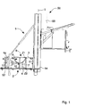
Figure 1 is a plan view of the supporting apparatus of the invention associated with a machine tool arranged in a first operating position, in which a frame is tilted to 0° with respect to an axis that is orthogonal to a cutting direction to make right-angle cuts; -
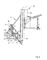
Figure 2 is a view like that inFigure 1 , illustrating the apparatus in a second operating position, in which the frame is tilted by -50° to make tilted cuts; -
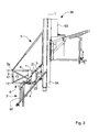
Figure 3 is a view like that inFigure 1 , illustrating the apparatus in a third operating position, in which the frame is tilted by +50° to make further tilted cuts. - A description of a preferred but non-limiting embodiment of the invention follows.
- The
machine tool 50, in particular a squaring machine for wooden panels, comprises aslide 51 that is slidable along a horizontal cutting direction T along awork surface 54 and an extendible supportingelement 5, known as a flag. - A
frame 2 of the articulated parallelogram type, provided with tworod elements slide 51 by a respective head element, known simply as a head. Eachrod element slide 51, so as to be able to perform rotational movements on a substantially horizontal table. Afurther rod element 52 is rotatably connected to the respective ends of the tworod elements - The
parallelogram frame 2 is indirectly supported by anend 5a of the extendible supportingelement 5. In fact, between theend 5a of the extendible supportingelement 5 and theparallelogram frame 2 there is interposed a further supportingelement 6, that thus acts as an intermediate element. - This further supporting
element 6 is made as a rigid rectangular perimeter that is defined by rods (sides or portions thereof). - The further supporting
element 6 comprises afirst portion 7 that connects the tworod elements second portion 8 that connects theend 5a of the extendible supportingelement 5 to saidfirst portion 7. - The
first portion 7 is positioned near theslide 51 so as to reduce the linear movements of said further supportingelement 6 caused by angular movements of saidrod elements - The
first portion 7 is fixed to therod elements work surface 54. - The axes Z1, Z2 are contained on a plane that is perpendicular to the
work surface 54 and substantially parallel to said cutting direction T. - The further supporting
element 6 further comprises athird portion 9 fixed to thesecond portion 8 and provided withhooking means 12 for fixing theend 5a to said further supportingelement 6 in a plurality of operating positions. In particular, the hooking means 12 comprises three different elements for anchoring the further supportingelement 6 on the extendible supporting element. The hooking means 12 enables the cutting strokes on the machine to be maximised. - The further supporting
element 6 further comprises afourth portion 10 for connecting thefirst portion 7 to thethird portion 9. - The
aforesaid portions - The method for connecting the further supporting
element 6 to said articulatedparallelogram frame 2 provides for thefirst portion 7 being rotatably connected (at each end thereof) respectively with each of therod elements frame 2, such that saidfirst portion 7 is defined by therod elements further rod element 52. Further, as mentioned above, this connection provides for thefirst portion 7 being arranged substantially near theslide 51. - In this manner, as the configurations of the
parallelogram frame 2 vary, thefirst portion 7 always remains parallel to thefurther rod element 52, or to theslide 51 and to the cutting direction T, and the linear movements of the further supporting element 6 - which, connected in this manner, simply translates - are substantially very reduced, also in relation to considerable angular travels performed by therod elements - The
end 5a of the extendible supportingelement 5 supports, by a spherical joint, the further supportingelement 6 at a point of thethird portion 9 thereof, and the further supportingelement 6 then supports theparallelogram frame 2. The supporting action is better obtainable if the aforesaid rotatable connections between thefirst portion 7 and therod elements - The extendible supporting
element 5 comprises a telescopic element, fixed by the spherical joint to the further supporting element (6) and by a rotatable cantilever joint to thebase 53 of themachine tool 50. - The apparatus of the invention enables the travels of the extendible supporting
element 5 to be minimised, enabling an extendible element, or flag, of standard type to be used and the slide strokes to be maximised at the same time. - Further, on the further supporting element (6) supporting
means 11 is provided, comprising in particular a plate on which slides, during rotation, theparallelogram frame 2, with the function of maximising the overall stiffness of the system by decreasing overall deflection originating from the thrust of the panel being machined. - The
parallelogram frame 2 is provided with a device for fine-adjusting the tilt, with a system for displaying the angular dimension and with a system for locking the parallelogram frame in position once the desired angular dimension has been reached. - The supporting apparatus of the invention can thus be used to make:
- right-angle cuts: the
frame 2 is maintained with the rods (3,4) orthogonal to the slidable slide (Figure 1 ; - tilted cuts: the
frame 2 is oriented at the desired angular dimension and locked in position (Figures 2 and3 ).
Claims (11)
- Supporting apparatus associable with a machine tool (50), in particular a circular saw machine, for supporting a workpiece made of wood or similar material, comprising:- a frame (2) of the articulated quadrilateral type including two rod elements (3, 4), that are rotatably connected to a slide (51) of said machine tool (50) that is movable along a cutting direction (T), and a connecting-rod element (14) opposite said slide (51) and connecting said rod elements (3, 4), and- extendible supporting means (5) connected to said machine tool (50) for supporting said frame (2), characterised in that said supporting apparatus comprises a further supporting element (6) interposed between said frame (2) and said extendible supporting means (5), said further supporting element (6) being rotatably connected to each of said two rod elements (3, 4) and to an end (5a) of said extendible supporting means (5).
- Apparatus according to claim 1, wherein said frame (2) is a four bar linkage.
- Apparatus according to claim 1 or 2, wherein said further supporting element (6) comprises at least a first portion (7) that connects said two rod elements (3, 4) and a second portion (8) that connects said end (5a) of said extendible supporting element (5) to said first portion (7).
- Apparatus according to claim 3, wherein said first portion (7) is positioned near said slide (51) so as to reduce the linear movements of said further supporting element (6) arising from angular movements of said rod elements (3, 4).
- Apparatus according to claim 3 or 4, wherein said first portion (7) is fixed to said rod elements (3, 4) rotatable around respective axes (Z1, Z2) that are parallel to one another and substantially perpendicular to a working surface (54) of said machine tool (50).
- Apparatus according to claim 5, wherein said axes (Z1, Z2) are contained on a plane that is perpendicular to said working surface (54) and substantially parallel to said cutting direction (T).
- Apparatus according to any one of claims 3 to 6, wherein said further supporting element (6) comprises a third portion (9) fixed to said second portion (8) and provided with hooking means (12) for fixing said end (5a) to said further supporting element (6) in a plurality of operating positions.
- Apparatus according to claim 7, wherein said further supporting element (6) comprises a fourth portion (10) for connecting said first portion (7) to said third portion (9).
- Apparatus according to claim 8, wherein said portions (7, 8, 9, 10) comprise respective elongated members, in particular rods defining a rectangle.
- Apparatus according to any preceding claim, comprising supporting means (11), fixed to said further supporting element (6) for slidably supporting at least a part of said frame (2).
- Apparatus according to any preceding claim, wherein said extendible supporting element (5) comprises a telescopic element fixed by a spherical joint to said further supporting element (6) and by a rotatable cantilever joint to a base (53) of said machine tool (50).
Applications Claiming Priority (1)
| Application Number | Priority Date | Filing Date | Title |
|---|---|---|---|
| ITMO2009A000053A IT1393148B1 (en) | 2009-03-11 | 2009-03-11 | SUPPORT SYSTEM |
Publications (2)
| Publication Number | Publication Date |
|---|---|
| EP2228184A1 true EP2228184A1 (en) | 2010-09-15 |
| EP2228184B1 EP2228184B1 (en) | 2012-11-14 |
Family
ID=41403970
Family Applications (1)
| Application Number | Title | Priority Date | Filing Date |
|---|---|---|---|
| EP20100155954 Not-in-force EP2228184B1 (en) | 2009-03-11 | 2010-03-09 | Workpiece supporting apparatus |
Country Status (2)
| Country | Link |
|---|---|
| EP (1) | EP2228184B1 (en) |
| IT (1) | IT1393148B1 (en) |
Cited By (1)
| Publication number | Priority date | Publication date | Assignee | Title |
|---|---|---|---|---|
| US20220203465A1 (en) * | 2019-05-16 | 2022-06-30 | Altendorf Gmbh | Transversal table for a woodworking machine and woodworking machine having such a transversal table, and method for controlling a woodworking machine |
Citations (2)
| Publication number | Priority date | Publication date | Assignee | Title |
|---|---|---|---|---|
| EP1205285A1 (en) * | 2000-11-10 | 2002-05-15 | Lazzari S.r.l. | Panel saw |
| DE20108153U1 (en) * | 2001-05-15 | 2002-09-19 | Otto Martin Maschinenbau GmbH & Co, 87724 Ottobeuren | Edging table movable in the cutting direction and woodworking machine with one edging table |
-
2009
- 2009-03-11 IT ITMO2009A000053A patent/IT1393148B1/en active
-
2010
- 2010-03-09 EP EP20100155954 patent/EP2228184B1/en not_active Not-in-force
Patent Citations (2)
| Publication number | Priority date | Publication date | Assignee | Title |
|---|---|---|---|---|
| EP1205285A1 (en) * | 2000-11-10 | 2002-05-15 | Lazzari S.r.l. | Panel saw |
| DE20108153U1 (en) * | 2001-05-15 | 2002-09-19 | Otto Martin Maschinenbau GmbH & Co, 87724 Ottobeuren | Edging table movable in the cutting direction and woodworking machine with one edging table |
Cited By (2)
| Publication number | Priority date | Publication date | Assignee | Title |
|---|---|---|---|---|
| US20220203465A1 (en) * | 2019-05-16 | 2022-06-30 | Altendorf Gmbh | Transversal table for a woodworking machine and woodworking machine having such a transversal table, and method for controlling a woodworking machine |
| US12350746B2 (en) * | 2019-05-16 | 2025-07-08 | Altendorf Gmbh | Transversal table for a woodworking machine and woodworking machine having such a transversal table, and method for controlling a woodworking machine |
Also Published As
| Publication number | Publication date |
|---|---|
| EP2228184B1 (en) | 2012-11-14 |
| ITMO20090053A1 (en) | 2010-09-12 |
| IT1393148B1 (en) | 2012-04-11 |
Similar Documents
| Publication | Publication Date | Title |
|---|---|---|
| US8191449B2 (en) | Position adjustable support for a cutting device | |
| US10780511B2 (en) | Foldable miter saw and foldable method of miter saw | |
| KR101027241B1 (en) | Wood cutting device with adjustable cutting angle | |
| US5862731A (en) | Multifunctional workbench for woodworking | |
| CN204135939U (en) | A kind of workbench for clamping sheet material | |
| EP3760399A1 (en) | Multiple spindle robot fixation device, processing system, and method for fixing object to be processed | |
| EP2228184B1 (en) | Workpiece supporting apparatus | |
| KR20060041987A (en) | Cutting tables for laminated glazing | |
| JP3210877U (en) | Five-axis portal manipulator | |
| CN107414167A (en) | Sheet cutting machine | |
| KR101944995B1 (en) | Circular Saw Machine | |
| CN211784353U (en) | Cutting sampler | |
| KR20230142900A (en) | Vertical plate cutting device | |
| CN110450214B (en) | Corner cutting machine and corner cutting method thereof | |
| KR101312535B1 (en) | Work talbe for cutting machine | |
| TWI504455B (en) | Moving mechanism for scroll sawing machines | |
| EP2982467A1 (en) | Machine for cutting wood panels or the like | |
| EP1074326A3 (en) | Cutting machine with a device for accurately aligning a circular saw and associated notching tool | |
| JP2005313574A (en) | Board material cutting device | |
| CN211362599U (en) | Oblique angle double-saw cutting machine | |
| KR100783573B1 (en) | Glass position holder for assembly | |
| EP2570215B1 (en) | Power saw | |
| CN210997681U (en) | Quick clamp for section bar processing | |
| CN210616983U (en) | Wafer cutting device for semiconductor packaging | |
| US10759040B2 (en) | Bar support for positioning a portion of a sheet material during sawing |
Legal Events
| Date | Code | Title | Description |
|---|---|---|---|
| PUAI | Public reference made under article 153(3) epc to a published international application that has entered the european phase |
Free format text: ORIGINAL CODE: 0009012 |
|
| AK | Designated contracting states |
Kind code of ref document: A1 Designated state(s): AT BE BG CH CY CZ DE DK EE ES FI FR GB GR HR HU IE IS IT LI LT LU LV MC MK MT NL NO PL PT RO SE SI SK SM TR |
|
| AX | Request for extension of the european patent |
Extension state: AL BA ME RS |
|
| 17P | Request for examination filed |
Effective date: 20110204 |
|
| GRAP | Despatch of communication of intention to grant a patent |
Free format text: ORIGINAL CODE: EPIDOSNIGR1 |
|
| RIC1 | Information provided on ipc code assigned before grant |
Ipc: B23D 47/02 20060101ALI20120427BHEP Ipc: B27B 5/22 20060101AFI20120427BHEP |
|
| GRAS | Grant fee paid |
Free format text: ORIGINAL CODE: EPIDOSNIGR3 |
|
| GRAA | (expected) grant |
Free format text: ORIGINAL CODE: 0009210 |
|
| RIN1 | Information on inventor provided before grant (corrected) |
Inventor name: PAZZINI, IVANO |
|
| AK | Designated contracting states |
Kind code of ref document: B1 Designated state(s): AT BE BG CH CY CZ DE DK EE ES FI FR GB GR HR HU IE IS IT LI LT LU LV MC MK MT NL NO PL PT RO SE SI SK SM TR |
|
| RAP1 | Party data changed (applicant data changed or rights of an application transferred) |
Owner name: SCM GROUP S.P.A. |
|
| REG | Reference to a national code |
Ref country code: GB Ref legal event code: FG4D |
|
| REG | Reference to a national code |
Ref country code: CH Ref legal event code: EP Ref country code: AT Ref legal event code: REF Ref document number: 583705 Country of ref document: AT Kind code of ref document: T Effective date: 20121115 |
|
| REG | Reference to a national code |
Ref country code: IE Ref legal event code: FG4D |
|
| REG | Reference to a national code |
Ref country code: DE Ref legal event code: R096 Ref document number: 602010003556 Country of ref document: DE Effective date: 20130110 |
|
| REG | Reference to a national code |
Ref country code: NL Ref legal event code: VDEP Effective date: 20121114 |
|
| REG | Reference to a national code |
Ref country code: AT Ref legal event code: MK05 Ref document number: 583705 Country of ref document: AT Kind code of ref document: T Effective date: 20121114 |
|
| REG | Reference to a national code |
Ref country code: LT Ref legal event code: MG4D |
|
| PG25 | Lapsed in a contracting state [announced via postgrant information from national office to epo] |
Ref country code: SE Free format text: LAPSE BECAUSE OF FAILURE TO SUBMIT A TRANSLATION OF THE DESCRIPTION OR TO PAY THE FEE WITHIN THE PRESCRIBED TIME-LIMIT Effective date: 20121114 Ref country code: LT Free format text: LAPSE BECAUSE OF FAILURE TO SUBMIT A TRANSLATION OF THE DESCRIPTION OR TO PAY THE FEE WITHIN THE PRESCRIBED TIME-LIMIT Effective date: 20121114 Ref country code: FI Free format text: LAPSE BECAUSE OF FAILURE TO SUBMIT A TRANSLATION OF THE DESCRIPTION OR TO PAY THE FEE WITHIN THE PRESCRIBED TIME-LIMIT Effective date: 20121114 Ref country code: ES Free format text: LAPSE BECAUSE OF FAILURE TO SUBMIT A TRANSLATION OF THE DESCRIPTION OR TO PAY THE FEE WITHIN THE PRESCRIBED TIME-LIMIT Effective date: 20130225 Ref country code: NO Free format text: LAPSE BECAUSE OF FAILURE TO SUBMIT A TRANSLATION OF THE DESCRIPTION OR TO PAY THE FEE WITHIN THE PRESCRIBED TIME-LIMIT Effective date: 20130214 Ref country code: HR Free format text: LAPSE BECAUSE OF FAILURE TO SUBMIT A TRANSLATION OF THE DESCRIPTION OR TO PAY THE FEE WITHIN THE PRESCRIBED TIME-LIMIT Effective date: 20121114 |
|
| PG25 | Lapsed in a contracting state [announced via postgrant information from national office to epo] |
Ref country code: PT Free format text: LAPSE BECAUSE OF FAILURE TO SUBMIT A TRANSLATION OF THE DESCRIPTION OR TO PAY THE FEE WITHIN THE PRESCRIBED TIME-LIMIT Effective date: 20130314 Ref country code: GR Free format text: LAPSE BECAUSE OF FAILURE TO SUBMIT A TRANSLATION OF THE DESCRIPTION OR TO PAY THE FEE WITHIN THE PRESCRIBED TIME-LIMIT Effective date: 20130215 Ref country code: SI Free format text: LAPSE BECAUSE OF FAILURE TO SUBMIT A TRANSLATION OF THE DESCRIPTION OR TO PAY THE FEE WITHIN THE PRESCRIBED TIME-LIMIT Effective date: 20121114 Ref country code: PL Free format text: LAPSE BECAUSE OF FAILURE TO SUBMIT A TRANSLATION OF THE DESCRIPTION OR TO PAY THE FEE WITHIN THE PRESCRIBED TIME-LIMIT Effective date: 20121114 Ref country code: BE Free format text: LAPSE BECAUSE OF FAILURE TO SUBMIT A TRANSLATION OF THE DESCRIPTION OR TO PAY THE FEE WITHIN THE PRESCRIBED TIME-LIMIT Effective date: 20121114 Ref country code: LV Free format text: LAPSE BECAUSE OF FAILURE TO SUBMIT A TRANSLATION OF THE DESCRIPTION OR TO PAY THE FEE WITHIN THE PRESCRIBED TIME-LIMIT Effective date: 20121114 |
|
| PG25 | Lapsed in a contracting state [announced via postgrant information from national office to epo] |
Ref country code: AT Free format text: LAPSE BECAUSE OF FAILURE TO SUBMIT A TRANSLATION OF THE DESCRIPTION OR TO PAY THE FEE WITHIN THE PRESCRIBED TIME-LIMIT Effective date: 20121114 |
|
| PG25 | Lapsed in a contracting state [announced via postgrant information from national office to epo] |
Ref country code: DK Free format text: LAPSE BECAUSE OF FAILURE TO SUBMIT A TRANSLATION OF THE DESCRIPTION OR TO PAY THE FEE WITHIN THE PRESCRIBED TIME-LIMIT Effective date: 20121114 Ref country code: BG Free format text: LAPSE BECAUSE OF FAILURE TO SUBMIT A TRANSLATION OF THE DESCRIPTION OR TO PAY THE FEE WITHIN THE PRESCRIBED TIME-LIMIT Effective date: 20130214 Ref country code: SK Free format text: LAPSE BECAUSE OF FAILURE TO SUBMIT A TRANSLATION OF THE DESCRIPTION OR TO PAY THE FEE WITHIN THE PRESCRIBED TIME-LIMIT Effective date: 20121114 Ref country code: EE Free format text: LAPSE BECAUSE OF FAILURE TO SUBMIT A TRANSLATION OF THE DESCRIPTION OR TO PAY THE FEE WITHIN THE PRESCRIBED TIME-LIMIT Effective date: 20121114 |
|
| PG25 | Lapsed in a contracting state [announced via postgrant information from national office to epo] |
Ref country code: NL Free format text: LAPSE BECAUSE OF FAILURE TO SUBMIT A TRANSLATION OF THE DESCRIPTION OR TO PAY THE FEE WITHIN THE PRESCRIBED TIME-LIMIT Effective date: 20121114 Ref country code: RO Free format text: LAPSE BECAUSE OF FAILURE TO SUBMIT A TRANSLATION OF THE DESCRIPTION OR TO PAY THE FEE WITHIN THE PRESCRIBED TIME-LIMIT Effective date: 20121114 Ref country code: IT Free format text: LAPSE BECAUSE OF FAILURE TO SUBMIT A TRANSLATION OF THE DESCRIPTION OR TO PAY THE FEE WITHIN THE PRESCRIBED TIME-LIMIT Effective date: 20121114 |
|
| PLBE | No opposition filed within time limit |
Free format text: ORIGINAL CODE: 0009261 |
|
| STAA | Information on the status of an ep patent application or granted ep patent |
Free format text: STATUS: NO OPPOSITION FILED WITHIN TIME LIMIT |
|
| 26N | No opposition filed |
Effective date: 20130815 |
|
| PG25 | Lapsed in a contracting state [announced via postgrant information from national office to epo] |
Ref country code: MC Free format text: LAPSE BECAUSE OF NON-PAYMENT OF DUE FEES Effective date: 20130331 |
|
| PG25 | Lapsed in a contracting state [announced via postgrant information from national office to epo] |
Ref country code: CY Free format text: LAPSE BECAUSE OF FAILURE TO SUBMIT A TRANSLATION OF THE DESCRIPTION OR TO PAY THE FEE WITHIN THE PRESCRIBED TIME-LIMIT Effective date: 20121114 |
|
| REG | Reference to a national code |
Ref country code: DE Ref legal event code: R097 Ref document number: 602010003556 Country of ref document: DE Effective date: 20130815 |
|
| REG | Reference to a national code |
Ref country code: IE Ref legal event code: MM4A |
|
| PG25 | Lapsed in a contracting state [announced via postgrant information from national office to epo] |
Ref country code: IE Free format text: LAPSE BECAUSE OF NON-PAYMENT OF DUE FEES Effective date: 20130309 |
|
| PG25 | Lapsed in a contracting state [announced via postgrant information from national office to epo] |
Ref country code: MT Free format text: LAPSE BECAUSE OF FAILURE TO SUBMIT A TRANSLATION OF THE DESCRIPTION OR TO PAY THE FEE WITHIN THE PRESCRIBED TIME-LIMIT Effective date: 20121114 |
|
| REG | Reference to a national code |
Ref country code: CH Ref legal event code: PL |
|
| GBPC | Gb: european patent ceased through non-payment of renewal fee |
Effective date: 20140309 |
|
| PGFP | Annual fee paid to national office [announced via postgrant information from national office to epo] |
Ref country code: FR Payment date: 20140410 Year of fee payment: 5 |
|
| PG25 | Lapsed in a contracting state [announced via postgrant information from national office to epo] |
Ref country code: GB Free format text: LAPSE BECAUSE OF NON-PAYMENT OF DUE FEES Effective date: 20140309 Ref country code: LI Free format text: LAPSE BECAUSE OF NON-PAYMENT OF DUE FEES Effective date: 20140331 Ref country code: CH Free format text: LAPSE BECAUSE OF NON-PAYMENT OF DUE FEES Effective date: 20140331 |
|
| PG25 | Lapsed in a contracting state [announced via postgrant information from national office to epo] |
Ref country code: SM Free format text: LAPSE BECAUSE OF FAILURE TO SUBMIT A TRANSLATION OF THE DESCRIPTION OR TO PAY THE FEE WITHIN THE PRESCRIBED TIME-LIMIT Effective date: 20121114 |
|
| PG25 | Lapsed in a contracting state [announced via postgrant information from national office to epo] |
Ref country code: TR Free format text: LAPSE BECAUSE OF FAILURE TO SUBMIT A TRANSLATION OF THE DESCRIPTION OR TO PAY THE FEE WITHIN THE PRESCRIBED TIME-LIMIT Effective date: 20121114 |
|
| PG25 | Lapsed in a contracting state [announced via postgrant information from national office to epo] |
Ref country code: MK Free format text: LAPSE BECAUSE OF FAILURE TO SUBMIT A TRANSLATION OF THE DESCRIPTION OR TO PAY THE FEE WITHIN THE PRESCRIBED TIME-LIMIT Effective date: 20121114 Ref country code: LU Free format text: LAPSE BECAUSE OF NON-PAYMENT OF DUE FEES Effective date: 20130309 Ref country code: HU Free format text: LAPSE BECAUSE OF FAILURE TO SUBMIT A TRANSLATION OF THE DESCRIPTION OR TO PAY THE FEE WITHIN THE PRESCRIBED TIME-LIMIT; INVALID AB INITIO Effective date: 20100309 |
|
| REG | Reference to a national code |
Ref country code: FR Ref legal event code: ST Effective date: 20151130 |
|
| PG25 | Lapsed in a contracting state [announced via postgrant information from national office to epo] |
Ref country code: FR Free format text: LAPSE BECAUSE OF NON-PAYMENT OF DUE FEES Effective date: 20150331 |
|
| PGFP | Annual fee paid to national office [announced via postgrant information from national office to epo] |
Ref country code: CZ Payment date: 20160303 Year of fee payment: 7 |
|
| PG25 | Lapsed in a contracting state [announced via postgrant information from national office to epo] |
Ref country code: IS Free format text: LAPSE BECAUSE OF FAILURE TO SUBMIT A TRANSLATION OF THE DESCRIPTION OR TO PAY THE FEE WITHIN THE PRESCRIBED TIME-LIMIT Effective date: 20121114 |
|
| PGFP | Annual fee paid to national office [announced via postgrant information from national office to epo] |
Ref country code: DE Payment date: 20160331 Year of fee payment: 7 |
|
| REG | Reference to a national code |
Ref country code: DE Ref legal event code: R119 Ref document number: 602010003556 Country of ref document: DE |
|
| PG25 | Lapsed in a contracting state [announced via postgrant information from national office to epo] |
Ref country code: CZ Free format text: LAPSE BECAUSE OF NON-PAYMENT OF DUE FEES Effective date: 20170309 |
|
| PG25 | Lapsed in a contracting state [announced via postgrant information from national office to epo] |
Ref country code: DE Free format text: LAPSE BECAUSE OF NON-PAYMENT OF DUE FEES Effective date: 20171003 |