EP2228111A1 - Game machine interface unit and game machine - Google Patents
Game machine interface unit and game machine Download PDFInfo
- Publication number
- EP2228111A1 EP2228111A1 EP08855941A EP08855941A EP2228111A1 EP 2228111 A1 EP2228111 A1 EP 2228111A1 EP 08855941 A EP08855941 A EP 08855941A EP 08855941 A EP08855941 A EP 08855941A EP 2228111 A1 EP2228111 A1 EP 2228111A1
- Authority
- EP
- European Patent Office
- Prior art keywords
- display
- interface unit
- display surface
- disposed
- panel
- Prior art date
- Legal status (The legal status is an assumption and is not a legal conclusion. Google has not performed a legal analysis and makes no representation as to the accuracy of the status listed.)
- Withdrawn
Links
Images


Classifications
-
- A63F13/06—
-
- A—HUMAN NECESSITIES
- A63—SPORTS; GAMES; AMUSEMENTS
- A63F—CARD, BOARD, OR ROULETTE GAMES; INDOOR GAMES USING SMALL MOVING PLAYING BODIES; VIDEO GAMES; GAMES NOT OTHERWISE PROVIDED FOR
- A63F13/00—Video games, i.e. games using an electronically generated display having two or more dimensions
- A63F13/20—Input arrangements for video game devices
- A63F13/21—Input arrangements for video game devices characterised by their sensors, purposes or types
- A63F13/214—Input arrangements for video game devices characterised by their sensors, purposes or types for locating contacts on a surface, e.g. floor mats or touch pads
-
- A—HUMAN NECESSITIES
- A63—SPORTS; GAMES; AMUSEMENTS
- A63F—CARD, BOARD, OR ROULETTE GAMES; INDOOR GAMES USING SMALL MOVING PLAYING BODIES; VIDEO GAMES; GAMES NOT OTHERWISE PROVIDED FOR
- A63F13/00—Video games, i.e. games using an electronically generated display having two or more dimensions
- A63F13/20—Input arrangements for video game devices
- A63F13/24—Constructional details thereof, e.g. game controllers with detachable joystick handles
-
- A—HUMAN NECESSITIES
- A63—SPORTS; GAMES; AMUSEMENTS
- A63F—CARD, BOARD, OR ROULETTE GAMES; INDOOR GAMES USING SMALL MOVING PLAYING BODIES; VIDEO GAMES; GAMES NOT OTHERWISE PROVIDED FOR
- A63F13/00—Video games, i.e. games using an electronically generated display having two or more dimensions
- A63F13/25—Output arrangements for video game devices
- A63F13/26—Output arrangements for video game devices having at least one additional display device, e.g. on the game controller or outside a game booth
-
- A—HUMAN NECESSITIES
- A63—SPORTS; GAMES; AMUSEMENTS
- A63F—CARD, BOARD, OR ROULETTE GAMES; INDOOR GAMES USING SMALL MOVING PLAYING BODIES; VIDEO GAMES; GAMES NOT OTHERWISE PROVIDED FOR
- A63F13/00—Video games, i.e. games using an electronically generated display having two or more dimensions
- A63F13/20—Input arrangements for video game devices
- A63F13/21—Input arrangements for video game devices characterised by their sensors, purposes or types
- A63F13/214—Input arrangements for video game devices characterised by their sensors, purposes or types for locating contacts on a surface, e.g. floor mats or touch pads
- A63F13/2145—Input arrangements for video game devices characterised by their sensors, purposes or types for locating contacts on a surface, e.g. floor mats or touch pads the surface being also a display device, e.g. touch screens
-
- A—HUMAN NECESSITIES
- A63—SPORTS; GAMES; AMUSEMENTS
- A63F—CARD, BOARD, OR ROULETTE GAMES; INDOOR GAMES USING SMALL MOVING PLAYING BODIES; VIDEO GAMES; GAMES NOT OTHERWISE PROVIDED FOR
- A63F13/00—Video games, i.e. games using an electronically generated display having two or more dimensions
- A63F13/50—Controlling the output signals based on the game progress
- A63F13/53—Controlling the output signals based on the game progress involving additional visual information provided to the game scene, e.g. by overlay to simulate a head-up display [HUD] or displaying a laser sight in a shooting game
-
- A—HUMAN NECESSITIES
- A63—SPORTS; GAMES; AMUSEMENTS
- A63F—CARD, BOARD, OR ROULETTE GAMES; INDOOR GAMES USING SMALL MOVING PLAYING BODIES; VIDEO GAMES; GAMES NOT OTHERWISE PROVIDED FOR
- A63F2300/00—Features of games using an electronically generated display having two or more dimensions, e.g. on a television screen, showing representations related to the game
- A63F2300/10—Features of games using an electronically generated display having two or more dimensions, e.g. on a television screen, showing representations related to the game characterized by input arrangements for converting player-generated signals into game device control signals
- A63F2300/1043—Features of games using an electronically generated display having two or more dimensions, e.g. on a television screen, showing representations related to the game characterized by input arrangements for converting player-generated signals into game device control signals being characterized by constructional details
-
- A—HUMAN NECESSITIES
- A63—SPORTS; GAMES; AMUSEMENTS
- A63F—CARD, BOARD, OR ROULETTE GAMES; INDOOR GAMES USING SMALL MOVING PLAYING BODIES; VIDEO GAMES; GAMES NOT OTHERWISE PROVIDED FOR
- A63F2300/00—Features of games using an electronically generated display having two or more dimensions, e.g. on a television screen, showing representations related to the game
- A63F2300/10—Features of games using an electronically generated display having two or more dimensions, e.g. on a television screen, showing representations related to the game characterized by input arrangements for converting player-generated signals into game device control signals
- A63F2300/1068—Features of games using an electronically generated display having two or more dimensions, e.g. on a television screen, showing representations related to the game characterized by input arrangements for converting player-generated signals into game device control signals being specially adapted to detect the point of contact of the player on a surface, e.g. floor mat, touch pad
- A63F2300/1075—Features of games using an electronically generated display having two or more dimensions, e.g. on a television screen, showing representations related to the game characterized by input arrangements for converting player-generated signals into game device control signals being specially adapted to detect the point of contact of the player on a surface, e.g. floor mat, touch pad using a touch screen
-
- A—HUMAN NECESSITIES
- A63—SPORTS; GAMES; AMUSEMENTS
- A63F—CARD, BOARD, OR ROULETTE GAMES; INDOOR GAMES USING SMALL MOVING PLAYING BODIES; VIDEO GAMES; GAMES NOT OTHERWISE PROVIDED FOR
- A63F2300/00—Features of games using an electronically generated display having two or more dimensions, e.g. on a television screen, showing representations related to the game
- A63F2300/30—Features of games using an electronically generated display having two or more dimensions, e.g. on a television screen, showing representations related to the game characterized by output arrangements for receiving control signals generated by the game device
- A63F2300/301—Features of games using an electronically generated display having two or more dimensions, e.g. on a television screen, showing representations related to the game characterized by output arrangements for receiving control signals generated by the game device using an additional display connected to the game console, e.g. on the controller
-
- A—HUMAN NECESSITIES
- A63—SPORTS; GAMES; AMUSEMENTS
- A63F—CARD, BOARD, OR ROULETTE GAMES; INDOOR GAMES USING SMALL MOVING PLAYING BODIES; VIDEO GAMES; GAMES NOT OTHERWISE PROVIDED FOR
- A63F2300/00—Features of games using an electronically generated display having two or more dimensions, e.g. on a television screen, showing representations related to the game
- A63F2300/30—Features of games using an electronically generated display having two or more dimensions, e.g. on a television screen, showing representations related to the game characterized by output arrangements for receiving control signals generated by the game device
- A63F2300/303—Features of games using an electronically generated display having two or more dimensions, e.g. on a television screen, showing representations related to the game characterized by output arrangements for receiving control signals generated by the game device for displaying additional data, e.g. simulating a Head Up Display
Abstract
Description
- The present invention relates to an interface unit for a game machine, where display function and input function are integrated.
- There is a known game apparatus includes an input device having plural transparent boards disposed on a surface of a CRT display, each of four corners of each transparent board being supported by a spring, the input device being provided in an on/off switchable manner by conductive bodies and electrodes displaced from the springs, each screen image on the display is caused to change for each transparent board, and it is competed to see whether or not push-down operation has been performed to the transparent board of a predetermined screen image (for example, cf. a patent document 1). Also, there is a known input device for a game machine where a display device causing a hit target to appear and disappear is disposed on the back surface of a transparent hit board where a plurality of hit detection devices are arranged, such that the display device and the hit board are corresponded to each other on one-to-one (for example, cl. a patent document 2).
- Patent Document 1:
JP-A-S56-152670
Patent Document 2:JP-A-2000-84233 - In the conventional game machine disclosed in the above prior-art documents, because operation members are disposed on an overall display surface of the display device, in order to display screen image with a different purpose from screen image for guiding operation timings, it is necessary to provide another display device. Therefore, it is not avoided that the number of parts increases, whereby the cost also increases.
- Then, the present invention aims to provide an interface unit for game machine which makes it possible to display screen image to be shown in association with operation members and screen image with a different purpose from that with a simple structure, and a game machine comprising the interface unit.
- An interface unit of one embodiment according to the present invention is an interface unit for a game machine, comprising: a display device having a single display surface; an input device overlaid on the single display surface; a first display part, in which a plurality of operation members are arranged on partical regions of the display surface in a push-down operable manner, each of the operation members having an operating part with enough transparency to allow a screen image on the display surface to be visually seen; and a second display part, which is set on a different part of the display surface from a part corresponding to the first display part, for displaying a screen image with a different purpose from that of the first display part, whereby the interface unit according to the present invention solves the above mentioned problem.
- According to the interface unit of the present invention, a single display surface of the display device is partitioned into the first display part and the second display part, and the plurality of operation members of the input device are arranged on the first display part. Thereby, it is enough to control the display on the display device in such a manner that while screen image relating to operation of the operation members is display on the first display, on the second display part, screen image with a different purpose is displayed. It is not necessary to prepare plural display devices for displaying both screen image for guiding operation timings and the like and screen image with a different purpose from that. Accordingly, as a structure of a game machine is simplified, it is possible to decrease the number of parts to reduce the cost.
- In one embodiment of the interface unit according to the present invention, the input device may be provided with a plate-like base composed of opaque material, the base being disposed between the display surface and the plurality of operation members and having first perforated holes, each of which corresponds to each operating part of the plurality of operation members in the first display part, a second perforated hole corresponding to the second display part. According to this embodiment, by overlaying the base on the display surface, it is possible that, while it is possible to display demanded image on each of the operation parts of the first display part and on the second display part, the part except the display parts is shielded from light.
- A partitioned member, which has a plurality of void parts between opaque frames, may be disposed on the base, in which each of the plurality of operation members is at each void part, the operation member may be provided with a flange on an outer periphery thereof, supporting means for supporting the operation member in a push-down operable manner and detecting means for detecting the push-down operation may disposed at a lower surface side of the flange, a wiring assembly, which is electrically connected to the detecting means, may be disposed along the frames at a lower surface side of the partitioned member, such that the wiring assembly reaches an outer periphery of the partitioned member. According to this embodiment, by the frames which is partitioned members, it is possible to ensure an electric connection route to each of the operation members from the outer periphery of the interface unit, with hiding the wiring extending to each detecting means.
- A transparent base board for ensuring rigidity of the input device may be disposed between the partitioned member and the display surface, and the operation members, the supporting means, the detecting means, and the wiring assembly may be disposed on the base board. According to this embodiment, by supporting component parts of the interface unit on the base board, it is possible to protect the display surface of the display device against load at the moment of push-down operation of the operation members.
- A cover extending along the frames may be disposed at an upper surface side of the partitioned member, such that the cover covers the flange. By covering the flange with the cover, it is possible to improve aesthetic sense of the interface unit, and moreover, protect the inside of each operation member from ingress of refuse such as gist and dust.
- The input device may be overlaid on the display surface in a state that the input device is structured as an assembled part, in which the base, the base board, the wiring assembly, the supporting means, the detecting means, the operation members, and the cover are combined. According to this embodiment, it is possible to built up the interface unit only by building up the input device and overlaying the input device on the display surface of the display device, which makes the treatment of the interface unit easy.
- Further, a game machine according to the present invention is a game machine having a structure, in which the interface unit mentioned above is mounted to a chassis, and a control unit, which controls display on the display surface of the display device such that screen images, each of which guides an operation timing of each of the plurality of operation members, are displayed respectively at the first display parts and the screen image with a different purpose is displayed at the second display part, whereby the game machine according to the present invention solves the above mentioned problem. According to this game machine, by using the single display surface of the display device, it is possible to display both screen image in association with the operation members and screen image with a different purpose from that. Accordingly, as a structure of a game machine is simplified, it is possible to decrease the number of parts to reduce the cost.
- As mentioned above, according to the present invention, the first display part and the second display unit are provided in the interface unit, and the plurality of operation members of the input device are arranged on the first display device. Because of that, the display of the display device is controlled in such a manner that, while screen image relating to operations of operation members is displayed on the first display part, in the second display part, screen image with a different purpose is displayed. Whereby, it is not necessary to prepare plural display devices in order to display both screen image for guiding operation timings and the like and screen image with a different purpose from that. Thereby, as a structure of a game machine is simplified, it is possible to decrease the number of parts to reduce the cost.
-
-
Fig. 1 shows a perspective view of a game machine to which one embodiment of an input device of the present invention is applied; -
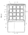
Fig.2 shows a plane view of the interface unit; -
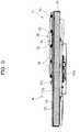
Fig.3 shows a sectional view of the interface unit of a set-up condition along the line III-III shown inFig.2 ; -
Fig.4 shows a sectional view of the interface unit of a disassemble condition; -
Fig.5 shows an exploded perspective view of the input module; -
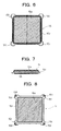
Fig.6 shows a plane view of the push button panel; -
Fig.7 shows a side view of the push button panel; -
Fig.8 shows a bottom view of the push button panel; -
Fig.9 shows an expanded view of IX portion shown inFig.3 ; -
Fig.10 shows a state that the push button panel is disposed in the void part of the lattice panel; -
Fig.11 shows an exploded perspective view with respect to the panel substrate, the lattice panel, the push button panel and the rubber contacts; -
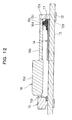
Fig.12 shows a sectional view along the line XII-XII shown inFig.10 ; and -
Fig.13 shows an example of game screen. -
Fig. 1 shows a schematic view of a game machine to which one embodiment of an input device of the present invention is applied. Thegame machine 1, which is installed in a commercial facility and the like, is configured as a game machine providing a player with a playing chance in exchange of consumption of a predetermined amount of play value. In thegame machine 1, achassis 2 is provided. At the front side of thechassis 2, acontrol panel part 3 is provided. In thecontrol panel part 3, aninterface unit 4 is provided in an inclined condition like a rising slop from a front edge thereof to an end edge thereof. Theinterface unit 4 is one unit into which display function and input function are integrated. The height of theinterface unit 4 is set in a range that an adult player of standard-tall can put naturally his/her fingers on theinterface unit 4. Additionally, the inclination angle to a horizontal plane of theinterface unit 4 is inclined to the horizontal plane, in such a manner that the player faces theinterface unit 4 when looking down diagonally forward with a kind of bent-over posture. Theinterface unit 4 is partitioned by aninput display part 4a as a first display part and a multipurpose display part 4b as a second display part. In theinput display part 4a, sixteen pieces ofpush button parts 4c are provided in such a manner that they are arranged in the shape of a matrix having 4 rows and 4 columns. -
Fig.2 shows a plane view of theinterface unit 4, andFig.3 shows a sectional view of theinterface unit 4 of a set-up condition, the sectional view being along the line III-III shown inFig.2 . As shown in these drawings, theinterface unit 4 has amonitor 10 as a display apparatus and aninput module 11 as an input device. As an example of themonitor 10, a liquid crystal display is employed, which has adisplay surface 10a the aspect ratio of which is set to sixteen to nine or the neighborhood thereof and is put on the market as a PC monitor. Of course, not only the liquid crystal display, various kinds of display such as an EL display and an LED display can be employed as themonitor 10. On the back surface of the monitor 10 (the lower surface inFig. 3 ), aterminal part 10b is provided to connect video cables or the like. -
Fig.4 shows a sectional view of theinterface unit 4 of a disassemble condition, andFig.5 shows an exploded perspective view of theinput module 11. As shown in these drawings, theinput module 11 is structured as an assembled part obtained by combining abase 12, alattice base 13,panel substrates 14, alattice panel 15,push button panels 16,rubber contacts 17 as plastic elastic bodies with electrodes, abutton cover 18 and alattice cover 19. Thebase 12 is a part functioning as a basal plate for joining the whole of theinput module 11 and thechassis 2. The size of the base 12 (a vertical and horizontal size) is set in a range that can cover completely thedisplay surface 10a of themonitor 10. Thebase 12 is configured as, for example, an opaque part obtained by applying sheet-metal processing to a metal plate. However, as long as thebase 12 is composed of opaque material, it is not necessary that thebase 12 is a metal product. In thebase 12, for recognizing screen image in themonitor parts 12a and a single display perforatedpart 12b are provided. The button perforatedparts 12a are first perforated holes corresponding to thepush button parts 4c on one-to-one, and are arranged in the shape of a matrix having 4 rows and 4 columns. The display perforatedpart 12b is a second perforated hole corresponding to the multipurpose display part 4b. The display perforatedpart 12b is in the shape of a rectangular, the width of which is slightly smaller than a entire width (the size in the right-left direction) of thedisplay surface 10a of themonitor 10. At each of both sides of thebase 12, a folding backpart 12c is formed. The folding backparts 12c are provided to fix theinput module 11 to thechassis 2. - The
lattice base 13 is a flat-plate-shaped base board to ensure rigidity of theinput module 11. The whole of thelattice base 13 is composed of transparent plastic. The size of thelattice base 13 is set to a degree that can cover the whole of the base 12 except the folding backparts 12c. Thepanel substrate 14 is a printed-wiring assembly for connecting electrically a control unit 30 (Fig. 1 ) of thegame machine 1 to eachrubber contact 17. Each of the panel substrates 14 is disposed on thelattice base 13 so as to be shared by two of thepush button parts 4c, onepush button part 4c is disposed on the outer periphery of theinput module 11 and the otherpush button part 4c abuts on the other one inward. Accordingly, the number of the panel substrates 14 is eight in total. By sharing sixteen pieces of thepush button parts 4c byplural panel substrates 14 in this way, it is possible to make lessen trouble to be required because of a fix or an exchange in the case when a part of thepanel substrate 14 does not work. Moreover, as each of fourpush button parts 4c disposed in a center part of theinput display part 4a and thepush button part 4c abutting on the outer periphery of the fourpush button parts 4c are mounted to thesame panel substrate 14, the electric wiring circuit for each of thepush button parts 4c disposed in the center part is provided so as to reach the outer periphery of theinput module 11, and it is possible to install wiring to thepush button parts 4c at the outer periphery of themodule 11. In addition, the panel substrates 14 has also perforatedparts 14a corresponding to thepush button parts 4c on one-to-one. - The
lattice panel 15 is a partitioned member for partitioning thedisplay surface 10a into plural areas corresponding to thepush button parts 4c respectively. Thelattice panel 15 is constructed by combining in the vertical and the horizontal direction in a reticular pattern, frames 15a composed of opaque plastic. The above mentionedpanel substrate 14 extends up to the outer periphery of themodule 11 along theframe 15a in such a manner that thepanel substrate 14 is covered by theframe 15a. Between theframes 15a of thelattice panel 15, sixteen pieces ofvoid parts 15b are provided in the same way as the button perforatedparts 12a in thebase 12. Thepush button panel 16 is provided as a part to accept a push-down operation by a player in theinput display part 4a. Thepush button panels 16 is disposed to thevoid parts 15b of thelattice panel 15 one by one. - As shown in
Figs.6 to 8 , thepush button panel 16 has a panelmain body 16a (the hatched part) in the shape of a substantial square flat plate, and aflange 16b disposed at the lower surface side of the panelmain body 16 so as to rim the periphery of the panelmain body 16a. At each of four corners of theflange 16b, anextended part 16c is provided as a part of theflange 16b, theextended part 16c protruding outward in the diagonal direction of thepush button panel 16. At the back surface (lower surface) side of eachextended part 16c, a recessedpart 16d in the shape of a circle is formed. Thepush button panel 16 is composed of transparent plastic, and mirror-like finishing was applied to the front, back and side surfaces of the panelmain body 16a. Thereby, the panelmain body 16a has a transparency enough high to recognize clearly the screen image in themonitor 10 therebelow. The panelmain body 16a corresponds to an operation part of thepush button part 4c. Blasting process was applied to theflange 16b (including theextended part 16c). Thereby, the transparency of theflange 16b is lessened to a state of a fogged glass. The transparency of theflange 16b is lessened in order not to see thepanel substrate 14, therubber contact 17, and the base 12 disposed under thepush button panel 16 through the panelmain body 16a. - Returning to
Figs. 4 and5 , therubber contact 17 is a part in which the electrodes for detecting the push-down operation of the push-down panel 16 are embedded in the rubber as the elastic body as supporting means which supports thepush button panel 16 in an up-and-down movable manner at the four corners. When therubber contact 17 is compressively deformed by the push-down operation to the push-down panel 16, the inside electrodes conduct electricity, and when the compressive deformation is released, the conduction by the inside electrodes is released. As this kind ofrubber contact 17, the one on the market can be employed. Thebutton cover 18 is provided to protect the inside of theinput module 11 from ingress of gist and dust, where avoid part 18a is formed for exposing the panelmain body 16a of thepush button panel 16. Thebutton cover 18 is an opaque part, for example, being composed of plastic. Thelattice cover 19 is provided as a facing panel for partitioning the push button parts 14c, wherevoid parts 19a are also formed for exposing the panelmain bodies 16a of thepush button panel 16. Thelattice panel 16 is an opaque part, for example, being composed of metal. -
Fig.9 shows an enlarged view of IX portion shown inFig.3 . Apparently as shown inFig.9 , in theinput module 11, thelattice base 13 is overlaid on the upper surface of thebase 12, and on the upper surface of thelattice base 13, thepanel substrate 14 and thelattice panel 15 are overlaid. At each of thevoid parts 15b in thelattice panel 15, therubber contact 17 is disposed so as to be overlaid on thepanel substrate 14. Thepush button panel 16 is attached on therubber contact 17 in such a manner that the recessedpart 16d in theextended part 16c is engaged with the top part of therubber contact 17. -
Fig.10 shows a plane view showing a state that thepush button panel 16 is disposed in thevoid part 15b of thelattice panel 15,Fig. 11 shows an exploded perspective view with respect to thepanel substrate 14, thelattice panel 15, thepush button panel 16 and therubber contacts 17.Fig. 12 shows a sectional view along the line XII-XII shown inFig. 10 . Apparently as shown in these drawings, in thelattice panel 15, the recessedparts 15c are provided in such a manner that thevoid part 15b is enlarged in the direction from each of the four corners of thevoid part 15b to an intersection point of theframes 15a of thelattice panel 15. At the recessedpart 15c, thepanel substrate 14 is exposed outside of theframe 15a of thelattice panel 15, and at the exposed part therubber contact 17 are disposed. Thepush button panel 16 is disposed in thevoid part 15b of thelattice panel 15 in such a manner that theextended part 16c at each of the four corners of thepush button panel 16 is engaged with the recessedpart 15c. In this way, theextended part 16c is provided at each of the four corners of thepush button panel 16 as an operation member, and therubber contact 17 as supporting means and detecting means is provided at the lower surface side of theextended part 16c. Because of that, it is possible to, while keeping supporting stably the push button panel, improve the sensibility of detection with respect to the push-down operation. Namely, as thepush button panel 16 is supported at the four corners, it is impossible to improve the supporting stability, and as the supported point and the detected point of the push-down operation are coincident with each other, even if thepush button panel 16 is pushed down obliquely to a normal line of the surface of the panelmain body 16a, it is possible to detect surely the operation by making the inside electrodes of any one of therubber contacts 17 conduct. Moreover, as therubber contact 17 is disposed inside the recessedpart 15c and at the lower side of theextended part 16c of each of the four corners, there is no possibility that position gaps could happen. Therefore, it is possible to detect surely the operation. Additionally, thepanel substrate 14 is covered by theframe 15a in a region except the recessedparts 15c. Moreover, thebase 12 is also covered by theframe 15a. - Returning to
Fig.9 , on the upper surface of thelattice panel 15, thebutton cover 18 and thelattice cover 19 are overlaid in such a manner that the panelmain body 16a protrudes from thevoid parts covers button cover 18, thelattice panel 15 and thelattice base 13 sequentially from thelattice cover 19. Thereby, theinput module 11 is built up integrally. In addition, by screwing a small screw inbase 12 through thelattice base 13, thepanel substrate 14 is fixed at a constant position. The built upinput module 11 is overlaid on thedisplay surface 10a of themonitor 10. Themonitor 10 is fixed to thecontrol panel part 3 of thechassis 2, theinput module 11 is overlaid on thedisplay surface 10a of themonitor 10 to screw the folding backpart 12a of the base 12 to thechasses 2. Thereby, Theinterface unit 4 is fixed to thechassis 2. Moreover, theframe 20 is also fixed to themonitor 10. Theframe 20 extends across entire width of themonitor 10 along the boundary between theinput display part 4a and the multipurpose display part 4b so as to partition theparts Fig.1 , a facingpanel 5 is provided to thechassis 2 in such a manner that the facingpanel 5 rims the periphery of theinput display part 4a of theinterface unit 4. On the boundary between theinput display part 4a and the multipurpose display part 4b, the facingpanel 5 is fixed to thechasses 2. By such an fitting structure, while themonitor 10 is shared between allpush button parts 4c and the multipurpose display part 4b in theinput display part 4a, it is possible to give an impression that they are different display parts from each other. - In the
game machine 1 which is structured as mentioned above, by thecontrol unit 30 provided in thechassis 2, different display control is executed between theinput display part 4a and the multipurpose display part 4b. Moreover, a predetermined game is executed by executing display controls which are independent of each other between thepush button parts 4c in theinput display part 4a. An example of a game screen is shown inFig. 13 . In this example, anoperation instruction image 31 is displayed at appropriatepush button parts 4c in theinput display part 4a, theoperation instruction image 31 instructing a timing to perform the push-down operation to thepush button part 4c where theimage 31 is displayed. The operation timing is predetermined, for example, to the music selected in the game. It is determined by thecontrol unit 30 based on a contact state of the inside electrodes in therubber contacts 17, whether or not thepush button part 4c has been pushed down to the timing instructed by theoperation instruction image 31. Based on the determination result, a game score of a player is calculated. In the multipurpose display part 4b, screen image with a different purpose from that of theinput display part 4a is properly displayed, the screen image being for example, various kinds of information to inform the player, such as a game score, operation instruction and the like, or screen image for setting the mood for the game. - The present invention is not limited to the above mentioned embodiment, and may be executed as various kinds of embodiments. For example, The number and the arrangement of the
push buttons 4c are not limited to the example shown in the drawings, and can be changed to various states. Also, the shape of the panelmain body 16a of thepush button panel 16 is not limited to the square flat plate, and can be properly changed to a circle-shaped flat plate, a polygonal shape except a quadrangle or the like. Whatever the case, as long as there is provided the structure that the plural extended parts are provided at the outer periphery of the operation member, each of the extended parts is engaged with the recess part of in the void part of the partitioning member put around the periphery of operation member, and the plastic elastic body with electrodes such as a rubber contact is disposed at the lower side of the operation member, it is possible to improve the detective sensibility of the push-down operation while improving the supporting stability of the operation members. Moreover, the structure of theinput module 11 as the input device is also not limited to the above mentioned embodiment, and the components such as the base and the lattice base can be properly added, deleted, and changed. The present invention is not limited to an example that the rubber contact corresponds to both of the supporting means and the detecting means, The present invention can be realized by preparing different parts corresponding to the supporting means and the detecting means respectively. Additionally, with respect to the light shielding of the boundary on the display surface between the first display part and the second display part and the boundary on the display surface between operation parts of the first display part, the embodiment is not limited to the light shielding by the base. It is possible to further improve the effects of shielding light by eliminating the regions on the display surface corresponding to the frames of the lattice panel provided on the base.
Claims (7)
- An interface unit for a game machine, comprising:a display device having a single display surface;an input device overlaid on the single display surface;a first display part, in which a plurality of operation members are arranged on partical regions of the display surface in a push-down operable manner, each of the operation members having an operating part with enough transparency to allow a screen image on the display surface to be visually seen; anda second display part, which is set on a different part of the display surface from a part corresponding to the first display part, for displaying a screen image with a different purpose from that of the first display part.
- The interface unit according to claim 1, wherein the input device is provided with a plate-like base composed of opaque material,
the base being disposed between the display surface and the plurality of operation members and having first perforated holes, each of which corresponds to each operating part of the plurality of operation members in the first display part, a second perforated hole corresponding to the second display part. - The interface unit according to claim 2, wherein a partitioned member, which has a plurality of void parts between opaque frames, is disposed on the base, in which each of the plurality of operation members is at each void part,
the operation member is provided with a flange on an outer periphery thereof,
supporting means for supporting the operation member in a push-down operable manner and detecting means for detecting the push-down operation are disposed at a lower surface side of the flange,
a wiring assembly, which is electrically connected to the detecting means, is disposed along the frames at a lower surface side of the partitioned member, such that the wiring assembly reaches an outer periphery of the partitioned member. - The interface unit according to claim 3, wherein a transparent base board for ensuring rigidity of the input device is disposed between the partitioned member and the display surface, and
the operation members, the supporting means, the detecting means, and the wiring assembly are disposed on the base board. - The interface unit according to claim 3 or 4, wherein a cover extending along the frames is disposed at an upper surface side of the partitioned member, such that the cover covers the flange.
- The interface unit according to claim 4 or 5, wherein the input device is overlaid on the display surface in a state that the input device is structured as an assembled part, in which the base, the base board, the wiring assembly, the supporting means, the detecting means, the operation members, and the cover are combined.
- A game machine having a structure, in which the interface unit according to any one of claims 1 to 6, is mounted to a chassis, and a control unit, which controls display on the display surface of the display device such that screen images, each of which guides an operation timing of each of the plurality of operation members, are displayed respectively at the first display parts and the screen image with a different purpose is displayed at the second display part.
Applications Claiming Priority (2)
| Application Number | Priority Date | Filing Date | Title |
|---|---|---|---|
| JP2007316330A JP4362531B2 (en) | 2007-12-06 | 2007-12-06 | Game machine interface unit and game machine |
| PCT/JP2008/071878 WO2009072490A1 (en) | 2007-12-06 | 2008-12-02 | Game machine interface unit and game machine |
Publications (2)
| Publication Number | Publication Date |
|---|---|
| EP2228111A1 true EP2228111A1 (en) | 2010-09-15 |
| EP2228111A4 EP2228111A4 (en) | 2011-09-07 |
Family
ID=40717669
Family Applications (1)
| Application Number | Title | Priority Date | Filing Date |
|---|---|---|---|
| EP08855941A Withdrawn EP2228111A4 (en) | 2007-12-06 | 2008-12-02 | Game machine interface unit and game machine |
Country Status (7)
| Country | Link |
|---|---|
| US (1) | US8854297B2 (en) |
| EP (1) | EP2228111A4 (en) |
| JP (1) | JP4362531B2 (en) |
| KR (1) | KR101189955B1 (en) |
| CN (2) | CN101888887B (en) |
| TW (1) | TW201000182A (en) |
| WO (1) | WO2009072490A1 (en) |
Families Citing this family (9)
| Publication number | Priority date | Publication date | Assignee | Title |
|---|---|---|---|---|
| US10150033B2 (en) * | 2010-08-20 | 2018-12-11 | Nintendo Co., Ltd. | Position calculation system, position calculation device, storage medium storing position calculation program, and position calculation method |
| JP5866825B2 (en) * | 2011-06-29 | 2016-02-24 | オムロン株式会社 | Switch unit and gaming machine |
| US11045726B2 (en) | 2013-12-31 | 2021-06-29 | Video Gaming Technologies, Inc. | Gaming machine having a curved display |
| US10363480B2 (en) | 2013-12-31 | 2019-07-30 | Video Gaming Technologies, Inc. | Gaming machine with a curved display |
| US9478097B2 (en) * | 2013-12-31 | 2016-10-25 | Video Gaming Technologies, Inc. | Gaming machine with a curved display |
| JP6237890B2 (en) * | 2014-04-18 | 2017-11-29 | 株式会社村田製作所 | Display device and program |
| JP6176639B1 (en) * | 2016-02-16 | 2017-08-09 | 株式会社コナミデジタルエンタテインメント | Game machine and input device thereof |
| KR101715888B1 (en) * | 2016-08-25 | 2017-03-13 | (주)넥스케이드 | Multi reel game machine to regulate betting |
| US10699514B2 (en) * | 2017-10-03 | 2020-06-30 | Bluberi Gaming Canada Inc. | Edge display having a LED matrix |
Citations (9)
| Publication number | Priority date | Publication date | Assignee | Title |
|---|---|---|---|---|
| WO1996014615A1 (en) * | 1994-11-07 | 1996-05-17 | Elonex Technologies, Inc. | Micro personal digital assistant with integrated cpu interface to system memory |
| GB2309570A (en) * | 1996-01-25 | 1997-07-30 | Jan Robert Coyle | Selective coin gaming machines |
| US5708840A (en) * | 1992-06-29 | 1998-01-13 | Elonex I.P. Holdings, Ltd. | Micro personal digital assistant |
| WO1998025556A1 (en) * | 1996-12-11 | 1998-06-18 | Chiron Vision Corporation | Remote control for ophthalmic surgical control console |
| US20040038721A1 (en) * | 2002-06-24 | 2004-02-26 | William Wells | System for interfacing a user and a casino gaming machine |
| US20040065187A1 (en) * | 1998-05-15 | 2004-04-08 | Ludwig Lester F. | Generalized electronic music interface |
| US20050276448A1 (en) * | 2000-07-07 | 2005-12-15 | Pryor Timothy R | Multi-functional control and entertainment systems |
| WO2006000050A1 (en) * | 2004-06-25 | 2006-01-05 | Aristocrat Technologies Australia Pty Ltd | Gaming machine screen partitioning |
| US20060068917A1 (en) * | 2004-09-21 | 2006-03-30 | Snoddy Jon H | System, method and handheld controller for multi-player gaming |
Family Cites Families (11)
| Publication number | Priority date | Publication date | Assignee | Title |
|---|---|---|---|---|
| US1016594A (en) | 1908-03-25 | 1912-02-06 | Carl Backus | Clamp and gage. |
| JPS56152670A (en) * | 1980-04-28 | 1981-11-26 | Masabumi Yoshida | Game device |
| JPH01249083A (en) * | 1988-03-30 | 1989-10-04 | H Ee L:Kk | Game machine |
| JP2000084233A (en) | 1998-09-09 | 2000-03-28 | Kinue Mogami | Target hitting game machine |
| JP4298871B2 (en) * | 1999-10-08 | 2009-07-22 | 矢崎総業株式会社 | Switch for display screen |
| JP2003029904A (en) * | 2000-06-05 | 2003-01-31 | Sony Corp | Information portable device and arranging method for operator in information portable device |
| US7841936B2 (en) * | 2001-07-16 | 2010-11-30 | Igt | System and method for presenting payouts in gaming systems |
| JP2005143714A (en) * | 2003-11-13 | 2005-06-09 | Omron Corp | Game device control method and game device |
| JP4127536B2 (en) | 2004-01-20 | 2008-07-30 | 任天堂株式会社 | GAME DEVICE AND GAME PROGRAM |
| US20050253821A1 (en) * | 2004-05-14 | 2005-11-17 | Roeder William H | Reduced-height terminal display with adaptive keyboard |
| US7988549B2 (en) * | 2006-09-26 | 2011-08-02 | Lightning Box Games Pty Limited | Electronic system for playing of reel-type games |
-
2007
- 2007-12-06 JP JP2007316330A patent/JP4362531B2/en active Active
-
2008
- 2008-12-02 US US12/746,368 patent/US8854297B2/en active Active
- 2008-12-02 WO PCT/JP2008/071878 patent/WO2009072490A1/en active Application Filing
- 2008-12-02 KR KR1020107014836A patent/KR101189955B1/en active IP Right Grant
- 2008-12-02 CN CN200880119236XA patent/CN101888887B/en active Active
- 2008-12-02 EP EP08855941A patent/EP2228111A4/en not_active Withdrawn
- 2008-12-02 CN CN201210129121.7A patent/CN102671377B/en active Active
- 2008-12-04 TW TW097147127A patent/TW201000182A/en unknown
Patent Citations (9)
| Publication number | Priority date | Publication date | Assignee | Title |
|---|---|---|---|---|
| US5708840A (en) * | 1992-06-29 | 1998-01-13 | Elonex I.P. Holdings, Ltd. | Micro personal digital assistant |
| WO1996014615A1 (en) * | 1994-11-07 | 1996-05-17 | Elonex Technologies, Inc. | Micro personal digital assistant with integrated cpu interface to system memory |
| GB2309570A (en) * | 1996-01-25 | 1997-07-30 | Jan Robert Coyle | Selective coin gaming machines |
| WO1998025556A1 (en) * | 1996-12-11 | 1998-06-18 | Chiron Vision Corporation | Remote control for ophthalmic surgical control console |
| US20040065187A1 (en) * | 1998-05-15 | 2004-04-08 | Ludwig Lester F. | Generalized electronic music interface |
| US20050276448A1 (en) * | 2000-07-07 | 2005-12-15 | Pryor Timothy R | Multi-functional control and entertainment systems |
| US20040038721A1 (en) * | 2002-06-24 | 2004-02-26 | William Wells | System for interfacing a user and a casino gaming machine |
| WO2006000050A1 (en) * | 2004-06-25 | 2006-01-05 | Aristocrat Technologies Australia Pty Ltd | Gaming machine screen partitioning |
| US20060068917A1 (en) * | 2004-09-21 | 2006-03-30 | Snoddy Jon H | System, method and handheld controller for multi-player gaming |
Non-Patent Citations (1)
| Title |
|---|
| See also references of WO2009072490A1 * |
Also Published As
| Publication number | Publication date |
|---|---|
| KR20100086081A (en) | 2010-07-29 |
| CN102671377B (en) | 2014-10-08 |
| TWI373358B (en) | 2012-10-01 |
| EP2228111A4 (en) | 2011-09-07 |
| KR101189955B1 (en) | 2012-10-12 |
| JP4362531B2 (en) | 2009-11-11 |
| TW201000182A (en) | 2010-01-01 |
| CN101888887B (en) | 2012-12-26 |
| JP2009136501A (en) | 2009-06-25 |
| CN102671377A (en) | 2012-09-19 |
| US20100321287A1 (en) | 2010-12-23 |
| WO2009072490A1 (en) | 2009-06-11 |
| CN101888887A (en) | 2010-11-17 |
| US8854297B2 (en) | 2014-10-07 |
Similar Documents
| Publication | Publication Date | Title |
|---|---|---|
| US8854297B2 (en) | Interface unit for game machine and game machine | |
| JP6430536B2 (en) | In-cell touch panel and display device | |
| US9256293B2 (en) | Button key assembly, operation panel, and image forming apparatus | |
| US20140029190A1 (en) | Electronic device | |
| WO2014017122A1 (en) | Electronic device | |
| EP2228112B1 (en) | Game machine input device | |
| JP7288700B2 (en) | game machine | |
| EP1876508A2 (en) | Support and protection device for a flat screen display, such as an LCD display | |
| CN113506530A (en) | Display panel and display device | |
| JP2022015269A (en) | Display device | |
| US20090036207A1 (en) | Multi-display gaming machine | |
| JP7421250B2 (en) | gaming machine | |
| KR200265780Y1 (en) | Infrared sensor type touch screen with separable control panel | |
| JP7445986B2 (en) | gaming machine | |
| JP7290347B2 (en) | game machine | |
| JP5738558B2 (en) | Front panel module, electronic equipment and karaoke equipment | |
| JP2023115138A (en) | game machine | |
| JP2015122112A (en) | Front panel module, electronic apparatus, and karaoke device | |
| JPH0588624A (en) | Display device |
Legal Events
| Date | Code | Title | Description |
|---|---|---|---|
| PUAI | Public reference made under article 153(3) epc to a published international application that has entered the european phase |
Free format text: ORIGINAL CODE: 0009012 |
|
| 17P | Request for examination filed |
Effective date: 20100629 |
|
| AK | Designated contracting states |
Kind code of ref document: A1 Designated state(s): AT BE BG CH CY CZ DE DK EE ES FI FR GB GR HR HU IE IS IT LI LT LU LV MC MT NL NO PL PT RO SE SI SK TR |
|
| AX | Request for extension of the european patent |
Extension state: AL BA MK RS |
|
| REG | Reference to a national code |
Ref country code: HK Ref legal event code: DE Ref document number: 1144795 Country of ref document: HK |
|
| DAX | Request for extension of the european patent (deleted) | ||
| A4 | Supplementary search report drawn up and despatched |
Effective date: 20110809 |
|
| RIC1 | Information provided on ipc code assigned before grant |
Ipc: A63F 13/06 20060101AFI20110803BHEP Ipc: A63F 13/08 20060101ALI20110803BHEP |
|
| STAA | Information on the status of an ep patent application or granted ep patent |
Free format text: STATUS: THE APPLICATION IS DEEMED TO BE WITHDRAWN |
|
| 18D | Application deemed to be withdrawn |
Effective date: 20140701 |
|
| REG | Reference to a national code |
Ref country code: HK Ref legal event code: WD Ref document number: 1144795 Country of ref document: HK |