EP2228025A1 - Port fixation using expandable threads - Google Patents
Port fixation using expandable threads Download PDFInfo
- Publication number
- EP2228025A1 EP2228025A1 EP10250429A EP10250429A EP2228025A1 EP 2228025 A1 EP2228025 A1 EP 2228025A1 EP 10250429 A EP10250429 A EP 10250429A EP 10250429 A EP10250429 A EP 10250429A EP 2228025 A1 EP2228025 A1 EP 2228025A1
- Authority
- EP
- European Patent Office
- Prior art keywords
- thread
- access
- surgical
- access member
- condition
- Prior art date
- Legal status (The legal status is an assumption and is not a legal conclusion. Google has not performed a legal analysis and makes no representation as to the accuracy of the status listed.)
- Withdrawn
Links
- 238000004873 anchoring Methods 0.000 claims abstract description 9
- 238000000034 method Methods 0.000 claims description 14
- 239000000560 biocompatible material Substances 0.000 claims description 4
- 208000014674 injury Diseases 0.000 description 4
- 239000000463 material Substances 0.000 description 4
- 238000001356 surgical procedure Methods 0.000 description 4
- 230000007704 transition Effects 0.000 description 4
- 230000008733 trauma Effects 0.000 description 4
- 238000003780 insertion Methods 0.000 description 3
- 230000037431 insertion Effects 0.000 description 3
- 238000002324 minimally invasive surgery Methods 0.000 description 2
- 238000012978 minimally invasive surgical procedure Methods 0.000 description 2
- 238000012986 modification Methods 0.000 description 2
- 230000004048 modification Effects 0.000 description 2
- 239000010935 stainless steel Substances 0.000 description 2
- 229910001220 stainless steel Inorganic materials 0.000 description 2
- RTAQQCXQSZGOHL-UHFFFAOYSA-N Titanium Chemical compound [Ti] RTAQQCXQSZGOHL-UHFFFAOYSA-N 0.000 description 1
- 210000001015 abdomen Anatomy 0.000 description 1
- 230000008901 benefit Effects 0.000 description 1
- 230000015572 biosynthetic process Effects 0.000 description 1
- 230000008859 change Effects 0.000 description 1
- 239000012530 fluid Substances 0.000 description 1
- 230000002401 inhibitory effect Effects 0.000 description 1
- 238000012830 laparoscopic surgical procedure Methods 0.000 description 1
- 210000003041 ligament Anatomy 0.000 description 1
- 230000007246 mechanism Effects 0.000 description 1
- 210000000056 organ Anatomy 0.000 description 1
- 238000011084 recovery Methods 0.000 description 1
- 239000010936 titanium Substances 0.000 description 1
- 229910052719 titanium Inorganic materials 0.000 description 1
Images


Classifications
-
- A—HUMAN NECESSITIES
- A61—MEDICAL OR VETERINARY SCIENCE; HYGIENE
- A61B—DIAGNOSIS; SURGERY; IDENTIFICATION
- A61B17/00—Surgical instruments, devices or methods
- A61B17/34—Trocars; Puncturing needles
- A61B17/3417—Details of tips or shafts, e.g. grooves, expandable, bendable; Multiple coaxial sliding cannulas, e.g. for dilating
- A61B17/3421—Cannulas
-
- A—HUMAN NECESSITIES
- A61—MEDICAL OR VETERINARY SCIENCE; HYGIENE
- A61B—DIAGNOSIS; SURGERY; IDENTIFICATION
- A61B17/00—Surgical instruments, devices or methods
- A61B17/34—Trocars; Puncturing needles
- A61B2017/348—Means for supporting the trocar against the body or retaining the trocar inside the body
- A61B2017/3482—Means for supporting the trocar against the body or retaining the trocar inside the body inside
- A61B2017/3484—Anchoring means, e.g. spreading-out umbrella-like structure
-
- A—HUMAN NECESSITIES
- A61—MEDICAL OR VETERINARY SCIENCE; HYGIENE
- A61B—DIAGNOSIS; SURGERY; IDENTIFICATION
- A61B17/00—Surgical instruments, devices or methods
- A61B17/34—Trocars; Puncturing needles
- A61B2017/348—Means for supporting the trocar against the body or retaining the trocar inside the body
- A61B2017/3482—Means for supporting the trocar against the body or retaining the trocar inside the body inside
- A61B2017/349—Trocar with thread on outside
Definitions
- the present disclosure relates to surgical access apparatus for positioning within an opening formed in a patient's tissue. More particularly, the present disclosure relates to surgical access apparatus that are repositionable to facilitate anchoring within a percutaneous opening, and capable of removably receiving one or more surgical instruments.
- a minimally invasive surgical procedure will include the use of a surgical access apparatus to facilitate entry into a surgical worksite positioned beneath the patient's tissue with surgical instrumentation, e.g., endoscopes, obturators, surgical staplers, and the like.
- a typical surgical access apparatus includes a cannula or access member defining a passageway through which the surgical instrumentation is inserted and the procedure is carried out.
- a surgical access apparatus that is positionable within a percutaneous tissue tract to facilitate access to an underlying surgical worksite.
- the surgical access apparatus includes an access member with a longitudinal opening defining an internal dimension suitable for the reception of a surgical instrument.
- the access member has a thread mounted thereon with proximal and distal ends that is movable relative to the access member, e.g., radially and/or axially, between a first condition and a second condition.
- the access member In the first condition, the access member defines a substantially uniform outer surface, and the thread provides the access member with a first outer dimension that allows for positioning of the access member within the tissue tract. In the second condition, the access member defines a substantially non-uniform outer surface, and the thread provides the access member with a second outer dimension that is larger than the first outer dimension to facilitate anchoring of the tubular member within the tissue tract.
- the access member is configured and dimensioned such that the internal dimension of the longitudinal opening extending through the access member remains substantially constant as the thread moves between the first and second conditions.
- the access member includes an outer surface with a helical recess having proximal and distal ends.
- the helical recess corresponds in configuration and dimensions to the thread such that the thread is received by the helical recess.
- the thread is rotatably received by the helical recess such that the thread is rotatable for movement between the first condition and the second condition.
- the thread may include a manual member extending outwardly therefrom that is configured and dimensioned for engagement by a clinician to facilitate rotation of the thread.
- the proximal end of the thread is displaced axially.
- the distal end of the thread may also be displaced axially, or alternatively, the distal end of the thread may remain in a substantially fixed axial location.
- the distal end of the helical recess may include a ramped portion that is configured and dimensioned to engage the distal end of the thread, whereby engagement of the distal end of the thread with the ramped portion causes the distal end of the thread to move onto the outer surface of the access member.
- the distal end of the thread may be fixedly secured to the access member, e.g., formed integrally therewith.
- the outer surface of the access member may include a cavity that is positioned at the distal end of the helical recess, and configured and dimensioned to receive the distal end of the thread to substantially inhibit axial movement thereof.
- the surgical access apparatus may further include a sheath that is positioned about at least a portion of the thread to inhibit contact between the thread and tissue.
- the disclosed surgical access apparatus may further include a housing having a proximal end, a distal end, and a opening extending therebetween that is configured and dimensioned for removable reception of the surgical instrument, and a seal member that is positioned within the housing and adapted to removably receive the surgical instrument such that a substantially fluid-tight seal is formed therewith.
- a method of percutaneously accessing a surgical worksite positioned beneath a patient's tissue includes the steps of (i) providing a surgical access apparatus having an access member with a longitudinal opening defining an internal dimension suitable for reception of a surgical instrument, and a thread mounted thereon that is movable relative to the access member; (ii) advancing the access member distally into an opening in the tissue; and (iii) transitioning the thread of the access member from a first condition to a second condition.
- the thread In the first condition, the thread provides the access member with a first outer dimension that allows for positioning of the access member within the tissue tract, and in the second condition, the thread provides the access member with a second outer dimension that is larger than the first outer dimension to facilitate anchoring of the tubular member within the tissue tract.
- the access member is configured and dimensioned such that the internal dimension of the longitudinal opening extending through the access member remains substantially constant as the thread moves between the first and second conditions.
- FIG. 1 is a side, schematic view of a surgical access apparatus including a housing, an access member, and a fixation member in accordance with one embodiment of the present disclosure, wherein the fixation member is shown separated from the access member;
- FIG. 2 is a distal end view of the housing and the access member seen in FIG. 1 ;
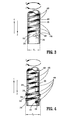
- FIG. 3 is a partial side, schematic view of the access member and the fixation member seen in FIG. 1 showing the access member in a contracted condition and the fixation member in a corresponding retracted position;
- FIG. 4 is a partial side, schematic view of the access member and the fixation member illustrated in FIG. 3 showing the access member in an expanded condition and the fixation member in a corresponding advanced position;
- FIG. 5 is a partial side, schematic view of an alternative embodiment of the present disclosure including a sheath positioned about at least a portion of the fixation member;
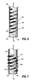
- FIG. 6 is a partial side, schematic view illustrating an alternative embodiment of the access member seen in FIG. 1 showing the access member in a contracted condition and the fixation member in a corresponding retracted position;
- FIG. 7 is a partial side, schematic view of the access member and the fixation member illustrated in FIG. 6 showing the access member in an expanded condition and the fixation member in a corresponding advanced position.
- proximal will refer to the end of the presently disclosed surgical access apparatus, or component thereof, that is closest to the clinician during proper use, while the term “distal” will refer to the end that is furthest from the clinician.
- tissue tract should be understood as referring to any opening in a patient's tissue, whether formed by the clinician or pre-existing.
- FIG. 1 illustrates a surgical access apparatus 10 in accordance with the principles of the present disclosure.
- the surgical access apparatus 10 is removably positionable within a tissue tract or opening 12 formed in a patient's tissue "T,” and is employable during the course of a surgical procedure, e.g., a minimally invasive procedure, to facilitate access to a surgical worksite "W," such as a patient's underlying cavities, tissues, organs, or the like, with one or more surgical instruments "I.”
- the disclosed surgical access apparatus 10 includes a housing 100, a seal assembly 200, and an access member 300 including a fixation member 400.
- the housing 100 may be fabricated from any suitable biocompatible material including moldable polymeric materials, stainless steel, titanium, or the like, and includes respective proximal and distal ends 102, 104.
- the housing 100 defines an internal cavity 106 that is configured and dimensioned to accommodate the seal assembly 200, and may be any structure suitable for this intended purpose.
- the housing 100 also includes a port 108 to permit the introduction of fluid, such as an insufflation gas in the case of a laparoscopic surgical procedure or an irrigant solution in the case of an arthroscopic surgical procedure, into the surgical worksite "W.”
- the seal assembly 200 is adapted to removably receive the surgical instrument "I" such that a substantially fluid-tight seal is formed therewith.
- suitable internal seals or valves are discussed in commonly assigned U.S. Patent Nos. 5,820,600 to Carlson, et al . and 6,702,787 to Racenet et al ., which issued on October 13, 1998 and March 9, 2004, respectively, the entire contents of which are incorporated by reference herein.
- the access member 300 extends distally from the housing 100, and is dimensioned for positioning within the tissue tract 12 formed in the patient's tissue "T.”
- the access member 300 includes respective proximal and distal ends 302, 304, and defines a longitudinal passageway 306 with an internal dimension "D A " ( FIG. 2 ).
- the longitudinal passageway 306 extends between the respective proximal and distal ends 302, 304 of the access member 300 along a longitudinal axis "A,” and is configured and dimensioned for the internal receipt of the surgical instrument "I.”
- the access member 300 defines an opening 308 at the distal end 304 thereof to allow the surgical instrument "I" to pass into the surgical worksite "W.”
- the fixation member 400 may be formed from any suitable material, including but not limited to stainless steel or polymeric materials.
- the fixation member 400 includes proximal and distal ends 402, 404, respectively, and is configured as a coiled, helical thread 406.
- the fixation member 400 is mounted coaxially about the access member 300. More specifically, the fixation member 400 is accommodated within a helical recess 310 ( FIG. 1 ) formed in the outer surface 316 of the access member 300 and including respective proximal and distal ends 312, 314.
- the configuration and dimensions of the helical recess 310 correspond to those of the fixation member 400 such that when the fixation member 400 is positioned within the helical recess 310, the outer surface 316 of the access member 300 is substantially uniform or smooth, as seen in FIG. 3 . Uniformity in the outer surface 316 of the access member 300 is desirable, in that such a surface minimizes the likelihood of tissue trauma upon distal advancement of the surgical apparatus 10 through the tissue tract 12 ( FIG. 1 ).
- the fixation member 400 is accommodated within the recess 310 formed in the outer surface 316 of the access member 300 such that the fixation member 400 is selectively rotatable. During rotation, the fixation member 400 is guided by the recess 310 such that the fixation member 400 moves axially along the longitudinal axis "A" between a retracted position ( FIG. 3 ) and an advanced position ( FIG. 4 ).
- the fixation member 400 moves axially along the longitudinal axis "A" between a retracted position ( FIG. 3 ) and an advanced position ( FIG. 4 ).
- the fixation member 400 will move axially in the direction of arrow 2 such that the respective proximal and distal ends 402, 404 of the fixation member 400 are displaced distally along the longitudinal axis "A" of the access member 300.
- the fixation member 400 will move axially in the direction of arrow 4 such that the respective proximal and distal ends 402, 404 of the fixation member 400 are displaced proximally along the longitudinal axis "A.”
- the fixation member may include a manual member 408 depending outwardly therefrom, as shown in FIGS. 1 .
- rotation of the fixation member 400 may be automated, e.g., driven by a motor 410 ( FIG. 1 ).
- the fixation member 400 when the fixation member 400 is in the retracted position ( FIG. 3 ), the access member 300 is in a corresponding contracted (first) condition.
- the fixation member 400 is advanced distally in the direction of arrow 2, the distal end 404 of the fixation member 400 engages a ramped portion 318 ( FIG. 3 ) included at the distal end 314 of the recess 310 formed in the outer surface 316 of the access member 300.
- the fixation member400 begins to emerge from the recess 310 for positioning about the outer surface 316 of the access member 300 such that the access member 300 transitions into an expanded (second) condition thereof ( FIG. 4 ).
- the outer surface 316 of the access member 300 is substantially uniform, as previously mentioned, and the access member 300 defines an outer dimension "D 1 .”
- the access member 300 when the access member 300 is in the expanded condition ( FIG. 4 ), the access member 300 includes an outer surface 316 that is non-uniform, or interrupted, due to the expansion experienced by the threads 406 of the fixation member 400.
- the outer surface 316 of the access member 300 defines an outer dimension "D 2 " in the expanded condition that is considerably larger than the outer dimension "D 1 " defined by the access member 300 in the contracted condition ( FIG. 3 ).
- the smaller outer dimension "D 1 " the access member 300 in the contracted condition ( FIG. 3 ) reduces the axial force necessary for advancement of the surgical apparatus 10 ( FIG. 1 ) into, and withdrawal of the surgical access apparatus 10 from, the tissue "T,” thereby reducing the axial force ultimately exerted upon the tissue "T,” which in turn, substantially minimizes the likelihood of trauma resulting therefrom.
- the larger dimension "D 2 " defined by the access member 300 in the expanded condition ( FIG. 4 ) anchors the access member 300 within the tissue tract 12 ( FIG. 1 ) until such time that the access member 300 is returned to the contracted position ( FIG. 3 ) via rotation of the fixation member 400, e.g., in the direction of arrow 3.
- the internal dimension "D A " ( FIG. 2 ) of the passageway 306 extending longitudinally through the access member 300 does not undergo any substantial change. Stated differently, the internal dimension "D A " of the passageway 306 remains substantially constant.
- rotation of the fixation member 400 may cause a distal surface 414 ( FIG. 4 ) of the threads 406 to engage the tissue "T" to facilitate proximal advancement of the access member 300.
- engagement of the distal surface 414 of the threads 406 with the tissue "T” may act to urge the access member 300 proximally from the tissue tract 12 ( FIG. 1 ) as the fixation member 400 is rotated, e.g., in the direction of arrow 3, thus allowing the access member 300 to be effectively screwed out of the tissue "T.”
- This screw-like motion will substantially limit the axial force exerted upon the tissue "T” during insertion and removal of the access member 300, thus substantially minimizing the likelihood of any trauma resulting therefrom.
- the clinician Prior to insertion of the surgical access apparatus 10, to facilitate placement and positioning of the access member 300 within the tissue tract 12, the clinician ensures that the fixation member 400 is in the retracted position ( FIG. 3 ), and consequently, that the access member 300 is in the contracted position. The clinician then positions the distal end 304 ( FIG. 1 ) of the access member 300 within the tissue tract 12 and advances the surgical access apparatus 10 towards the tissue "T" until the distal end 404 of the fixation member 400 is positioned beneath the tissue "T.” Thereafter, the clinician effectuates rotation of the fixation member 400, e.g., via the manual member 408 ( FIG. 1 ), to move the fixation member from the retracted position ( FIG. 3 ) into the advanced position ( FIG. 4 ), and thereby transition the access member 300 into the expanded condition.
- the fixation member 400 Prior to insertion of the surgical access apparatus 10, to facilitate placement and positioning of the access member 300 within the tissue tract 12, the clinician ensures that the fixation member 400 is in the retracted position ( FIG. 3
- the fixation member 400 rotates, e.g., in the direction of arrow 1, the fixation member 400 moves distally along the longitudinal axis "A" of the access member 300 in the direction of arrow 2 until the distal end 404 of the fixation member 400 engages the ramped portion 318 ( FIG. 3 ). Engagement with the ramped portion 318 causes the distal end 404 of the fixation member to ride up onto the outer surface 316 of the access member 300, thereby transitioning the access member 300 transitions into the expanded (second) condition ( FIG. 4 ), and anchoring the surgical access apparatus 10 within the tissue tract 12 ( FIG. 1 ). The surgical instrument "I” can then be inserted into, and advanced distally through, the passageway 306 ( FIGS. 1, 2 ) extending through the access member 300 to carry out the surgical procedure through the surgical access apparatus 10.
- the clinician rotates the fixation member 400, e.g., in the direction of arrow 3, such that the fixation member 400 moves proximally along the longitudinal axis "A" of the access member 300 in the direction of arrow 4.
- the fixation member 400 will recede into the recess 310 ( FIG. 1 ) formed in the outer surface 316 of the access member 300, thereby returning the fixation member 400 to the retracted position ( FIG. 3 ) and the access member 300 to the contracted position.
- the surgical access apparatus 10 can then be withdrawn from the tissue tract 12 ( FIG. 1 ), and the tissue tract 12 can be closed.
- the surgical access apparatus 10 may further include a sheath or guard 500 that is positioned about the fixation member 400 to inhibit contact between the fixation member 400 and the tissue "T" ( FIG. 1 ).
- the sheath 500 may be positioned about the entirety of the fixation member 400, or alternatively, about only a portion of the fixation member 400, as shown in FIG. 5 .
- the sheath 500 may be formed from any suitable biocompatible material, including but not limited to polymeric materials or rubber.
- FIGS. 6 and 7 illustrate an alternate embodiment of the presently disclosed access member, which is identified by the reference characters 1300, in conjunction with the fixation member 400 discussed above with respect to FIGS. 1-4 .
- the access member 1300 is substantially similar to the aforedescribed access member 300, and accordingly, will only be discussed with respect to its differences therefrom.
- the access member 1300 is adapted to permit relative movement between the proximal end 402 of the fixation member 400 and the access member 1300 during rotation of the fixation member 400, while substantially preventing relative movement between the distal end 404 of the fixation member 400 and the access member 1300.
- rotation of the fixation member 400 i.e., to cause movement from the retracted position ( FIG. 6 ) to the advanced position ( FIG. 7 )
- This approximation in turn causes outward expansion of the fixation member 400, i.e., away from the longitudinal axis "A," such that access member 1300 realizes the expanded condition illustrated in FIG. 7 .
- the distal end 404 of the fixation member 400 may be received by a pocket or cavity 1320 formed in the access member 1300. As the fixation member 400 rotates, e.g., in the direction of arrow 1 ( FIG. 6 ), the distal end 404 thereof engages the internal surfaces of the cavity 1320, thereby inhibiting movement of the distal end 404 of the fixation member 400 relative to the and the access member 1300. Alternatively, it is envisioned that the distal end 404 of the fixation member 400 may be secured to, e.g., integrally formed with, the access member 1300 to prevent relative movement therebetween.
- the surgical access apparatus 10 may include any suitable mechanism.
- the surgical access apparatus 10 may incorporate ratcheting structure (not shown) associated with either or both of the access member 1300 and the fixation member 400.
- the surgical access apparatus may include a lockable collar, or other such structure, that is engagable with the fixation member 400 and repositionable along the longitudinal axis "A" of the access member 1300.
Landscapes
- Health & Medical Sciences (AREA)
- Surgery (AREA)
- Life Sciences & Earth Sciences (AREA)
- Biomedical Technology (AREA)
- Nuclear Medicine, Radiotherapy & Molecular Imaging (AREA)
- Engineering & Computer Science (AREA)
- Pathology (AREA)
- Heart & Thoracic Surgery (AREA)
- Medical Informatics (AREA)
- Molecular Biology (AREA)
- Animal Behavior & Ethology (AREA)
- General Health & Medical Sciences (AREA)
- Public Health (AREA)
- Veterinary Medicine (AREA)
- Surgical Instruments (AREA)
Abstract
The present disclosure describes a surgical access apparatus including an access member with a longitudinal opening defining an internal dimension suitable for removable receipt of a surgical instrument. The access member has a thread mounted thereon that is movable between a first condition and a second condition. When the thread is in the first condition, the access member defines a first outer dimension that allows for positioning of the access member within a tissue tract, and when the thread is in the second condition, the access member defines a second, larger outer dimension to facilitate anchoring of the access member within the tissue tract. As the thread moves between the first and second conditions, the internal dimension of the longitudinal opening extending through the access member remains substantially constant.
Description
- The present application claims the benefit of and priority to
U.S. Provisional Application Serial No. 61/158,818 filed on March 10, 2009 - The present disclosure relates to surgical access apparatus for positioning within an opening formed in a patient's tissue. More particularly, the present disclosure relates to surgical access apparatus that are repositionable to facilitate anchoring within a percutaneous opening, and capable of removably receiving one or more surgical instruments.
- In contemporary medical practice, many surgical procedures are performed through small incisions formed in the skin, as compared to the larger incisions typically required in traditional procedures, in an effort to reduce both patient trauma and recovery time. Generally, such procedures are referred to as "endoscopic," unless performed in the patient's abdomen, in which case the procedure is referred to as "laparoscopic," or on a joint, ligament, or the like, in which case the procedure is referred to as "arthroscopic." Throughout the present disclosure, "endoscopic," "laparoscopic," and "arthroscopic" procedures may be collectively referred to as "minimally invasive" procedures.
- Typically, a minimally invasive surgical procedure will include the use of a surgical access apparatus to facilitate entry into a surgical worksite positioned beneath the patient's tissue with surgical instrumentation, e.g., endoscopes, obturators, surgical staplers, and the like. A typical surgical access apparatus includes a cannula or access member defining a passageway through which the surgical instrumentation is inserted and the procedure is carried out.
- While many varieties of surgical access apparatus are known in the art, a continuing need exists for a surgical access apparatus that may be releasably and reliably secured within the patient's tissue during the course of a minimally invasive procedure.
- In one aspect of the present disclosure, a surgical access apparatus is disclosed that is positionable within a percutaneous tissue tract to facilitate access to an underlying surgical worksite. The surgical access apparatus includes an access member with a longitudinal opening defining an internal dimension suitable for the reception of a surgical instrument. The access member has a thread mounted thereon with proximal and distal ends that is movable relative to the access member, e.g., radially and/or axially, between a first condition and a second condition.
- In the first condition, the access member defines a substantially uniform outer surface, and the thread provides the access member with a first outer dimension that allows for positioning of the access member within the tissue tract. In the second condition, the access member defines a substantially non-uniform outer surface, and the thread provides the access member with a second outer dimension that is larger than the first outer dimension to facilitate anchoring of the tubular member within the tissue tract. The access member is configured and dimensioned such that the internal dimension of the longitudinal opening extending through the access member remains substantially constant as the thread moves between the first and second conditions.
- The access member includes an outer surface with a helical recess having proximal and distal ends. The helical recess corresponds in configuration and dimensions to the thread such that the thread is received by the helical recess. Specifically, the thread is rotatably received by the helical recess such that the thread is rotatable for movement between the first condition and the second condition. In one embodiment, the thread may include a manual member extending outwardly therefrom that is configured and dimensioned for engagement by a clinician to facilitate rotation of the thread.
- As the thread moves between the first condition and the second condition, the proximal end of the thread is displaced axially. The distal end of the thread may also be displaced axially, or alternatively, the distal end of the thread may remain in a substantially fixed axial location. In those embodiments wherein the distal end of the thread is displaced axially as the thread moves between the first condition and the second condition, it is envisioned that the distal end of the helical recess may include a ramped portion that is configured and dimensioned to engage the distal end of the thread, whereby engagement of the distal end of the thread with the ramped portion causes the distal end of the thread to move onto the outer surface of the access member. In those embodiments wherein the distal end of the thread remains in a substantially fixed axial location as the thread moves between the first condition and the second condition, it is envisioned that the distal end of the thread may be fixedly secured to the access member, e.g., formed integrally therewith. Alternatively, it is envisioned that the outer surface of the access member may include a cavity that is positioned at the distal end of the helical recess, and configured and dimensioned to receive the distal end of the thread to substantially inhibit axial movement thereof.
- In an alternative embodiment of the present disclosure, the surgical access apparatus may further include a sheath that is positioned about at least a portion of the thread to inhibit contact between the thread and tissue.
- The disclosed surgical access apparatus may further include a housing having a proximal end, a distal end, and a opening extending therebetween that is configured and dimensioned for removable reception of the surgical instrument, and a seal member that is positioned within the housing and adapted to removably receive the surgical instrument such that a substantially fluid-tight seal is formed therewith.
- In another aspect of the present disclosure, a method of percutaneously accessing a surgical worksite positioned beneath a patient's tissue is disclosed. The method includes the steps of (i) providing a surgical access apparatus having an access member with a longitudinal opening defining an internal dimension suitable for reception of a surgical instrument, and a thread mounted thereon that is movable relative to the access member; (ii) advancing the access member distally into an opening in the tissue; and (iii) transitioning the thread of the access member from a first condition to a second condition.
- In the first condition, the thread provides the access member with a first outer dimension that allows for positioning of the access member within the tissue tract, and in the second condition, the thread provides the access member with a second outer dimension that is larger than the first outer dimension to facilitate anchoring of the tubular member within the tissue tract. The access member is configured and dimensioned such that the internal dimension of the longitudinal opening extending through the access member remains substantially constant as the thread moves between the first and second conditions.
- These and other features of the surgical access apparatus disclosed herein will become more readily apparent to those skilled in the art through reference to the detailed description of various embodiments of the present disclosure that follows.
- The use of a biocompatible material in the preparation of a surgical access apparatus comprising:
- an access member including a longitudinal opening defining an internal dimension suitable for reception of a surgical instrument, the access member having mounted thereon on a thread being movable relative to the access member; for use in a method of percutaneously accessing a surgical worksite positioned beneath a patient's tissue, the method comprising the steps of:
- providing the access apparatus
- advancing the access member distally into an opening in the tissue; and
- transitioning the thread of the access member from a first condition, in which the thread provide the access member with a first outer dimension to allow for positioning of the access member within the tissue tract, to a second condition, in which the thread provides the access member with a second outer dimension larger than the first outer dimension to facilitate anchoring of the tubular member within the tissue tract, wherein the access member is configured and dimensioned such that the internal dimension of the longitudinal opening extending through the access member remains substantially constant as the thread moves between the first and second conditions.
- Various embodiments of the present disclosure are described herein below with references to the drawings, wherein:
-
FIG. 1 is a side, schematic view of a surgical access apparatus including a housing, an access member, and a fixation member in accordance with one embodiment of the present disclosure, wherein the fixation member is shown separated from the access member; -
FIG. 2 is a distal end view of the housing and the access member seen inFIG. 1 ; -
FIG. 3 is a partial side, schematic view of the access member and the fixation member seen inFIG. 1 showing the access member in a contracted condition and the fixation member in a corresponding retracted position; -
FIG. 4 is a partial side, schematic view of the access member and the fixation member illustrated inFIG. 3 showing the access member in an expanded condition and the fixation member in a corresponding advanced position; -
FIG. 5 is a partial side, schematic view of an alternative embodiment of the present disclosure including a sheath positioned about at least a portion of the fixation member; -
FIG. 6 is a partial side, schematic view illustrating an alternative embodiment of the access member seen inFIG. 1 showing the access member in a contracted condition and the fixation member in a corresponding retracted position; and -
FIG. 7 is a partial side, schematic view of the access member and the fixation member illustrated inFIG. 6 showing the access member in an expanded condition and the fixation member in a corresponding advanced position. - In the drawings, and in the following description, like references numerals will identify similar or identical elements. Throughout the following description, the term "proximal" will refer to the end of the presently disclosed surgical access apparatus, or component thereof, that is closest to the clinician during proper use, while the term "distal" will refer to the end that is furthest from the clinician. Additionally, the term "tissue tract" should be understood as referring to any opening in a patient's tissue, whether formed by the clinician or pre-existing.
-
FIG. 1 illustrates asurgical access apparatus 10 in accordance with the principles of the present disclosure. Thesurgical access apparatus 10 is removably positionable within a tissue tract or opening 12 formed in a patient's tissue "T," and is employable during the course of a surgical procedure, e.g., a minimally invasive procedure, to facilitate access to a surgical worksite "W," such as a patient's underlying cavities, tissues, organs, or the like, with one or more surgical instruments "I." The disclosedsurgical access apparatus 10 includes ahousing 100, aseal assembly 200, and anaccess member 300 including afixation member 400. - The
housing 100 may be fabricated from any suitable biocompatible material including moldable polymeric materials, stainless steel, titanium, or the like, and includes respective proximal anddistal ends housing 100 defines aninternal cavity 106 that is configured and dimensioned to accommodate theseal assembly 200, and may be any structure suitable for this intended purpose. As depicted inFIG. 1 , thehousing 100 also includes aport 108 to permit the introduction of fluid, such as an insufflation gas in the case of a laparoscopic surgical procedure or an irrigant solution in the case of an arthroscopic surgical procedure, into the surgical worksite "W." - The
seal assembly 200 is adapted to removably receive the surgical instrument "I" such that a substantially fluid-tight seal is formed therewith. Examples of suitable internal seals or valves are discussed in commonly assignedU.S. Patent Nos. 5,820,600 to Carlson, et al . and6,702,787 to Racenet et al ., which issued on October 13, 1998 and March 9, 2004, respectively, the entire contents of which are incorporated by reference herein. - The
access member 300 extends distally from thehousing 100, and is dimensioned for positioning within thetissue tract 12 formed in the patient's tissue "T." Theaccess member 300 includes respective proximal anddistal ends longitudinal passageway 306 with an internal dimension "DA" (FIG. 2 ). Thelongitudinal passageway 306 extends between the respective proximal anddistal ends access member 300 along a longitudinal axis "A," and is configured and dimensioned for the internal receipt of the surgical instrument "I." Theaccess member 300 defines anopening 308 at thedistal end 304 thereof to allow the surgical instrument "I" to pass into the surgical worksite "W." - Referring now to
FIGS. 3 and 4 as well, thefixation member 400 will be discussed. Thefixation member 400 may be formed from any suitable material, including but not limited to stainless steel or polymeric materials. Thefixation member 400 includes proximal anddistal ends helical thread 406. - The
fixation member 400 is mounted coaxially about theaccess member 300. More specifically, thefixation member 400 is accommodated within a helical recess 310 (FIG. 1 ) formed in theouter surface 316 of theaccess member 300 and including respective proximal anddistal ends helical recess 310 correspond to those of thefixation member 400 such that when thefixation member 400 is positioned within thehelical recess 310, theouter surface 316 of theaccess member 300 is substantially uniform or smooth, as seen inFIG. 3 . Uniformity in theouter surface 316 of theaccess member 300 is desirable, in that such a surface minimizes the likelihood of tissue trauma upon distal advancement of thesurgical apparatus 10 through the tissue tract 12 (FIG. 1 ). - The
fixation member 400 is accommodated within therecess 310 formed in theouter surface 316 of theaccess member 300 such that thefixation member 400 is selectively rotatable. During rotation, thefixation member 400 is guided by therecess 310 such that thefixation member 400 moves axially along the longitudinal axis "A" between a retracted position (FIG. 3 ) and an advanced position (FIG. 4 ). For example, in the embodiment of theaccess member 300 discussed with respect toFIGS. 1-4 , as thefixation member 400 is rotated in the direction ofarrow 1, the fixation member will move axially in the direction ofarrow 2 such that the respective proximal anddistal ends fixation member 400 are displaced distally along the longitudinal axis "A" of theaccess member 300. Similarly, as thefixation member 400 is rotated in the direction ofarrow 3, the fixation member will move axially in the direction of arrow 4 such that the respective proximal anddistal ends fixation member 400 are displaced proximally along the longitudinal axis "A." To facilitate rotation, the fixation member may include amanual member 408 depending outwardly therefrom, as shown inFIGS. 1 . Alternatively, however, rotation of thefixation member 400 may be automated, e.g., driven by a motor 410 (FIG. 1 ). - Referring still to
FIGS. 1-4 , when thefixation member 400 is in the retracted position (FIG. 3 ), theaccess member 300 is in a corresponding contracted (first) condition. However, as thefixation member 400 is advanced distally in the direction ofarrow 2, thedistal end 404 of thefixation member 400 engages a ramped portion 318 (FIG. 3 ) included at thedistal end 314 of therecess 310 formed in theouter surface 316 of theaccess member 300. When thedistal end 404 of thefixation member 400 engages the rampedportion 318, the fixation member400 begins to emerge from therecess 310 for positioning about theouter surface 316 of theaccess member 300 such that theaccess member 300 transitions into an expanded (second) condition thereof (FIG. 4 ). - In the contracted condition (
FIG. 3 ), theouter surface 316 of theaccess member 300 is substantially uniform, as previously mentioned, and theaccess member 300 defines an outer dimension "D1." In contrast, when theaccess member 300 is in the expanded condition (FIG. 4 ), theaccess member 300 includes anouter surface 316 that is non-uniform, or interrupted, due to the expansion experienced by thethreads 406 of thefixation member 400. As seen inFIG. 4 , theouter surface 316 of theaccess member 300 defines an outer dimension "D2" in the expanded condition that is considerably larger than the outer dimension "D1" defined by theaccess member 300 in the contracted condition (FIG. 3 ). - The smaller outer dimension "D1" the
access member 300 in the contracted condition (FIG. 3 ) reduces the axial force necessary for advancement of the surgical apparatus 10 (FIG. 1 ) into, and withdrawal of thesurgical access apparatus 10 from, the tissue "T," thereby reducing the axial force ultimately exerted upon the tissue "T," which in turn, substantially minimizes the likelihood of trauma resulting therefrom. The larger dimension "D2" defined by theaccess member 300 in the expanded condition (FIG. 4 ) anchors theaccess member 300 within the tissue tract 12 (FIG. 1 ) until such time that theaccess member 300 is returned to the contracted position (FIG. 3 ) via rotation of thefixation member 400, e.g., in the direction ofarrow 3. - As the
access member 300 transitions between the contracted and expanded conditions, the internal dimension "DA" (FIG. 2 ) of thepassageway 306 extending longitudinally through theaccess member 300 does not undergo any substantial change. Stated differently, the internal dimension "DA" of thepassageway 306 remains substantially constant. - During insertion of the
access member 300 through the tissue tract 12 (FIG. 1 ), it is envisioned herein that rotation of thefixation member 400 may cause a proximal surface 412 (FIG. 4 ) of thethreads 406 to engage the tissue "T" to facilitate further distal advancement of theaccess member 300. Specifically, engagement of the proximal surface 412 of thethreads 406 with the tissue "T" may act to urge theaccess member 300 distally through thetissue tract 12 as thefixation member 400 is rotated, e.g., in the direction ofarrow 1, thus allowing theaccess member 300 to be effectively screwed into the tissue "T." Similarly, during withdrawal of theaccess member 300 from the tissue tract 12 (FIG. 1 ), it is envisioned that rotation of thefixation member 400 may cause a distal surface 414 (FIG. 4 ) of thethreads 406 to engage the tissue "T" to facilitate proximal advancement of theaccess member 300. Specifically, engagement of the distal surface 414 of thethreads 406 with the tissue "T" may act to urge theaccess member 300 proximally from the tissue tract 12 (FIG. 1 ) as thefixation member 400 is rotated, e.g., in the direction ofarrow 3, thus allowing theaccess member 300 to be effectively screwed out of the tissue "T." This screw-like motion will substantially limit the axial force exerted upon the tissue "T" during insertion and removal of theaccess member 300, thus substantially minimizing the likelihood of any trauma resulting therefrom. - With continued reference to
FIGS. 1-4 , the use and function of the surgical access apparatus 10 (FIG. 1 ) will be discussed during the course of a typical minimally invasive surgical procedure subsequent to formation of thetissue tract 12. - Prior to insertion of the
surgical access apparatus 10, to facilitate placement and positioning of theaccess member 300 within thetissue tract 12, the clinician ensures that thefixation member 400 is in the retracted position (FIG. 3 ), and consequently, that theaccess member 300 is in the contracted position. The clinician then positions the distal end 304 (FIG. 1 ) of theaccess member 300 within thetissue tract 12 and advances thesurgical access apparatus 10 towards the tissue "T" until thedistal end 404 of thefixation member 400 is positioned beneath the tissue "T." Thereafter, the clinician effectuates rotation of thefixation member 400, e.g., via the manual member 408 (FIG. 1 ), to move the fixation member from the retracted position (FIG. 3 ) into the advanced position (FIG. 4 ), and thereby transition theaccess member 300 into the expanded condition. - As the
fixation member 400 rotates, e.g., in the direction ofarrow 1, thefixation member 400 moves distally along the longitudinal axis "A" of theaccess member 300 in the direction ofarrow 2 until thedistal end 404 of thefixation member 400 engages the ramped portion 318 (FIG. 3 ). Engagement with the rampedportion 318 causes thedistal end 404 of the fixation member to ride up onto theouter surface 316 of theaccess member 300, thereby transitioning theaccess member 300 transitions into the expanded (second) condition (FIG. 4 ), and anchoring thesurgical access apparatus 10 within the tissue tract 12 (FIG. 1 ). The surgical instrument "I" can then be inserted into, and advanced distally through, the passageway 306 (FIGS. 1, 2 ) extending through theaccess member 300 to carry out the surgical procedure through thesurgical access apparatus 10. - After completing the procedure and withdrawing the surgical instrument "I" from the
access member 300, the clinician rotates thefixation member 400, e.g., in the direction ofarrow 3, such that thefixation member 400 moves proximally along the longitudinal axis "A" of theaccess member 300 in the direction of arrow 4. Continued rotation will cause thefixation member 400 to recede into the recess 310 (FIG. 1 ) formed in theouter surface 316 of theaccess member 300, thereby returning thefixation member 400 to the retracted position (FIG. 3 ) and theaccess member 300 to the contracted position. Thesurgical access apparatus 10 can then be withdrawn from the tissue tract 12 (FIG. 1 ), and thetissue tract 12 can be closed. - Referring now to
FIG. 5 , the surgical access apparatus 10 (FIG. 1 ) may further include a sheath orguard 500 that is positioned about thefixation member 400 to inhibit contact between thefixation member 400 and the tissue "T" (FIG. 1 ). Thesheath 500 may be positioned about the entirety of thefixation member 400, or alternatively, about only a portion of thefixation member 400, as shown inFIG. 5 . Thesheath 500 may be formed from any suitable biocompatible material, including but not limited to polymeric materials or rubber. -
FIGS. 6 and 7 illustrate an alternate embodiment of the presently disclosed access member, which is identified by thereference characters 1300, in conjunction with thefixation member 400 discussed above with respect toFIGS. 1-4 . Theaccess member 1300 is substantially similar to theaforedescribed access member 300, and accordingly, will only be discussed with respect to its differences therefrom. - The
access member 1300 is adapted to permit relative movement between theproximal end 402 of thefixation member 400 and theaccess member 1300 during rotation of thefixation member 400, while substantially preventing relative movement between thedistal end 404 of thefixation member 400 and theaccess member 1300. As a result, rotation of thefixation member 400, i.e., to cause movement from the retracted position (FIG. 6 ) to the advanced position (FIG. 7 ), results in approximation of the respective proximal anddistal ends fixation member 400. This approximation in turn causes outward expansion of thefixation member 400, i.e., away from the longitudinal axis "A," such thataccess member 1300 realizes the expanded condition illustrated inFIG. 7 . - In one embodiment, as seen in
FIGS. 6 and 7 , it is envisioned that thedistal end 404 of thefixation member 400 may be received by a pocket orcavity 1320 formed in theaccess member 1300. As thefixation member 400 rotates, e.g., in the direction of arrow 1 (FIG. 6 ), thedistal end 404 thereof engages the internal surfaces of thecavity 1320, thereby inhibiting movement of thedistal end 404 of thefixation member 400 relative to the and theaccess member 1300. Alternatively, it is envisioned that thedistal end 404 of thefixation member 400 may be secured to, e.g., integrally formed with, theaccess member 1300 to prevent relative movement therebetween. - To maintain the expanded condition of the access member 1300 (
FIG. 7 ), and thus, anchoring of the surgical access apparatus 10 (FIG. 1 ) within the tissue "T," thesurgical access apparatus 10 may include any suitable mechanism. For example, thesurgical access apparatus 10 may incorporate ratcheting structure (not shown) associated with either or both of theaccess member 1300 and thefixation member 400. Alternatively, the surgical access apparatus may include a lockable collar, or other such structure, that is engagable with thefixation member 400 and repositionable along the longitudinal axis "A" of theaccess member 1300. - The above description, disclosure, and figures should not be construed as limiting, but merely as exemplary of particular embodiments. It is to be understood, therefore, that the disclosure is not limited to the precise embodiments described, and that various other changes and modifications may be effected by one skilled in the art without departing from the scope or spirit of the disclosure. Additionally, those skilled in the art will appreciate that the elements and features illustrated or described in connection with one embodiment can be combined with those of another, and that such modifications and variations are also intended to be included within the scope of the present disclosure.
Claims (15)
- A surgical access apparatus for positioning within a percutaneous tissue tract to facilitate access to an underlying surgical worksite, the surgical access apparatus comprising:an access member including a longitudinal opening defining an internal dimension suitable for reception of a surgical instrument, the access member having mounted thereon a thread with proximal and distal ends, the thread being movable relative to the access member.
- The surgical access apparatus of claim 1, wherein the thread is radially moveable relative to the access member.
- The surgical access apparatus of claim 1 or claim 2, wherein the thread is axially moveable relative to the access member.
- The surgical access apparatus of any preceding claim, wherein the thread is moveable between a first condition, in which the thread provides the access member with a first outer dimension to allow for positioning of the access member within the tissue tract, and a second condition, in which the thread provides the access member with a second outer dimension larger than the first outer dimension to facilitate anchoring of the tubular member within the tissue tract.
- The surgical access apparatus of claim 4, wherein the access member is configured and dimensioned such that the internal dimension of the longitudinal opening extending through the access member remains substantially constant as the thread moves between the first and second conditions.
- The surgical access apparatus of claim 4, wherein the access member defines a substantially uniform outer surface when the thread is in the first condition and a non-uniform outer surface when the thread is in the second condition.
- The surgical access apparatus of claim 4, wherein the access member includes an outer surface with a helical recess having proximal and distal ends and corresponding in configuration and dimensions to the thread such that the thread is received by the helical recess.
- The surgical access apparatus of claim 7, wherein the thread is rotatably received by the helical recess such that the thread is rotatable for movement between the first condition and the second condition, preferably wherein the thread includes a manual member configured and dimensioned for engagement by a clinician to facilitate rotation of the thread.
- The surgical access apparatus of claim 7 or claim 8, wherein the manual member is dimensioned to extend outwardly from the thread.
- The surgical access apparatus of claim 7, wherein the proximal end of the thread is displaced axially as the thread moves between the first condition and the second condition, preferable wherein the distal end of the thread is displaced axially as the thread moves between the first condition and the second condition.
- The surgical access apparatus of claim 10, wherein the distal end of the helical recess includes a ramped portion configured and dimensioned to engage the distal end of the thread as the thread moves in a distal direction during movement from the first condition to the second condition, whereby engagement of the distal end of the thread and the ramped portion causes the distal end of the thread to move onto the outer surface of the access member.
- The surgical access apparatus of claim 11, wherein the distal end of the thread remains in a substantially fixed axial location as the thread moves between the first condition and the second condition.
- The surgical access apparatus of claim 12, wherein the distal end of the thread is fixedly secured to the access member or the surgical access apparatus of claim 12, wherein the distal end of the thread is formed integrally with the access member and/or the surgical access apparatus of claim 12, wherein the outer surface of the access member includes a cavity positioned at the distal end of the helical recess, the cavity being configured and dimensioned to receive the distal end of the thread to substantially inhibit axial movement thereof.
- The surgical access apparatus of any preceding claim, wherein the surgical access apparatus further includes a housing having a proximal end, a distal end, and a opening extending therebetween configured and dimensioned for removable reception of the surgical instrument, and a seal member positioned within the housing, the seal member being adapted to removably receive the surgical instrument such that a substantially fluid-tight seal is formed therewith and/or the surgical access apparatus of claim 1, wherein the surgical access apparatus further includes a sheath positioned about at least a portion of the thread to inhibit contact between the thread and tissue.
- The use of a biocompatible material in the preparation of a surgical access apparatus comprising:an access member including a longitudinal opening defining an internal dimension suitable for reception of a surgical instrument, the access member having mounted thereon a thread being movable relative to the access member; for use in a method of percutaneously accessing a surgical worksite positioned beneath a patient's tissue, the method comprising the steps of:providing the access apparatusadvancing the access member distally into an opening in the tissue; andtransitioning the thread of the access member from a first condition, in which the thread provides the access member with a first outer dimension to allow for positioning of the access member within the tissue tract, to a second condition, in which the thread provides the access member with a second outer dimension larger than the first outer dimension to facilitate anchoring of the tubular member within the tissue tract, wherein the access member is configured and dimensioned such that the internal dimension of the longitudinal opening extending through the access member remains substantially constant as the thread moves between the first and second conditions.
Applications Claiming Priority (2)
| Application Number | Priority Date | Filing Date | Title |
|---|---|---|---|
| US15881809P | 2009-03-10 | 2009-03-10 | |
| US12/697,611 US7857789B2 (en) | 2009-03-10 | 2010-02-01 | Port fixation using expandable threads |
Publications (1)
| Publication Number | Publication Date |
|---|---|
| EP2228025A1 true EP2228025A1 (en) | 2010-09-15 |
Family
ID=42199202
Family Applications (1)
| Application Number | Title | Priority Date | Filing Date |
|---|---|---|---|
| EP10250429A Withdrawn EP2228025A1 (en) | 2009-03-10 | 2010-03-09 | Port fixation using expandable threads |
Country Status (5)
| Country | Link |
|---|---|
| US (1) | US7857789B2 (en) |
| EP (1) | EP2228025A1 (en) |
| JP (1) | JP2010207573A (en) |
| AU (1) | AU2010200583A1 (en) |
| CA (1) | CA2692621A1 (en) |
Families Citing this family (7)
| Publication number | Priority date | Publication date | Assignee | Title |
|---|---|---|---|---|
| US8574220B2 (en) * | 2006-02-28 | 2013-11-05 | Olympus Endo Technology America Inc. | Rotate-to-advance catheterization system |
| US8870755B2 (en) | 2007-05-18 | 2014-10-28 | Olympus Endo Technology America Inc. | Rotate-to-advance catheterization system |
| US9339264B2 (en) | 2010-10-01 | 2016-05-17 | Cook Medical Technologies Llc | Port access visualization platform |
| US20110082370A1 (en) * | 2009-10-02 | 2011-04-07 | Wilson-Cook Medical Inc. | Endoscopic fascia tunneling |
| AU2010300450B2 (en) * | 2009-10-02 | 2013-10-31 | Cook Medical Technologies Llc | Apparatus for single port access |
| US9132065B2 (en) | 2012-04-30 | 2015-09-15 | Cook Medical Technologies Llc | Enteral feeding percutaneous access clip |
| CN112702963B (en) * | 2018-09-21 | 2025-01-03 | 朝日英达科株式会社 | Dilator |
Citations (5)
| Publication number | Priority date | Publication date | Assignee | Title |
|---|---|---|---|---|
| US5820600A (en) | 1996-05-14 | 1998-10-13 | Innerdyne, Inc. | Adjustable introducer valve |
| US20020193734A1 (en) * | 2001-05-17 | 2002-12-19 | Moenning Stephen P. | Body cavity access assembly and an associated medical procedure for dispensing a liquid |
| US6702787B2 (en) | 1997-05-02 | 2004-03-09 | Tyco Healthcare Group Lp | Trocar seal system |
| WO2004078026A2 (en) * | 2003-03-03 | 2004-09-16 | Applied Medical Resources Corporation | Surgical access apparatus and method |
| US20070225650A1 (en) * | 2006-03-21 | 2007-09-27 | Applied Medical Resources Corporation | Cannula stabilization seal |
Family Cites Families (10)
| Publication number | Priority date | Publication date | Assignee | Title |
|---|---|---|---|---|
| US1621159A (en) * | 1925-11-27 | 1927-03-15 | Robert T Evans | Abdominoscope |
| GB955490A (en) | 1961-08-02 | 1964-04-15 | Rupert Brooke | Improvements in or relating to catheters |
| US4043338A (en) * | 1973-04-30 | 1977-08-23 | Ortho Pharmaceutical Corporation | Pharmaceutical formulation applicator device |
| US4250873A (en) * | 1977-04-26 | 1981-02-17 | Richard Wolf Gmbh | Endoscopes |
| US4608965A (en) * | 1985-03-27 | 1986-09-02 | Anspach Jr William E | Endoscope retainer and tissue retracting device |
| US5209735A (en) * | 1988-11-07 | 1993-05-11 | Lazarus Harrison M | External guide wire and enlargement means |
| US4886500A (en) * | 1988-11-07 | 1989-12-12 | Lazarus Harrison M | External guide wire |
| US5217441A (en) * | 1989-08-15 | 1993-06-08 | United States Surgical Corporation | Trocar guide tube positioning device |
| US5257975A (en) * | 1992-08-14 | 1993-11-02 | Edward Weck Incorporated | Cannula retention device |
| US6056766A (en) * | 1998-06-09 | 2000-05-02 | Thompson; Ronald J. | Stabilized trocar, and method of using same |
-
2010
- 2010-02-01 US US12/697,611 patent/US7857789B2/en not_active Expired - Fee Related
- 2010-02-09 CA CA2692621A patent/CA2692621A1/en not_active Abandoned
- 2010-02-17 AU AU2010200583A patent/AU2010200583A1/en not_active Abandoned
- 2010-02-24 JP JP2010039398A patent/JP2010207573A/en active Pending
- 2010-03-09 EP EP10250429A patent/EP2228025A1/en not_active Withdrawn
Patent Citations (5)
| Publication number | Priority date | Publication date | Assignee | Title |
|---|---|---|---|---|
| US5820600A (en) | 1996-05-14 | 1998-10-13 | Innerdyne, Inc. | Adjustable introducer valve |
| US6702787B2 (en) | 1997-05-02 | 2004-03-09 | Tyco Healthcare Group Lp | Trocar seal system |
| US20020193734A1 (en) * | 2001-05-17 | 2002-12-19 | Moenning Stephen P. | Body cavity access assembly and an associated medical procedure for dispensing a liquid |
| WO2004078026A2 (en) * | 2003-03-03 | 2004-09-16 | Applied Medical Resources Corporation | Surgical access apparatus and method |
| US20070225650A1 (en) * | 2006-03-21 | 2007-09-27 | Applied Medical Resources Corporation | Cannula stabilization seal |
Also Published As
| Publication number | Publication date |
|---|---|
| AU2010200583A1 (en) | 2010-09-30 |
| JP2010207573A (en) | 2010-09-24 |
| US20100234806A1 (en) | 2010-09-16 |
| US7857789B2 (en) | 2010-12-28 |
| CA2692621A1 (en) | 2010-09-10 |
Similar Documents
| Publication | Publication Date | Title |
|---|---|---|
| US7857789B2 (en) | Port fixation using expandable threads | |
| AU762195B2 (en) | Self-retaining surgical access instrument | |
| EP2138113B1 (en) | Button port | |
| EP2044897B1 (en) | Expanding seal anchor for single incision surgery | |
| EP1675500B1 (en) | Expandible surgical access device | |
| US10124156B2 (en) | Surgical access port and method of using same | |
| US8114053B2 (en) | Port fixation with interlocking structure | |
| US6638265B1 (en) | Laparoscopy cannula adapter and assembly | |
| EP2465450A1 (en) | Self Deploying Bodily Opening Protector | |
| EP2314227A1 (en) | Wound closure device including direct-driven needle | |
| US20100262166A1 (en) | Systems and methods for suture anchor deployment | |
| US8292870B2 (en) | Port fixation with filament actuating member | |
| WO2007127655A2 (en) | Dilating stylet and cannula | |
| US20140206942A1 (en) | Hybrid cannula and methods for manufacturing the same | |
| US20110196206A1 (en) | Port fixation with varying thread diameter | |
| US20130053776A1 (en) | Surgical Access Device with Adjustable Cannula | |
| US20200268283A1 (en) | Tissue thickness measuring device | |
| CN109984783B (en) | A suture assembly for sutured holes | |
| CN109984814A (en) | A kind of fixation kit |
Legal Events
| Date | Code | Title | Description |
|---|---|---|---|
| PUAI | Public reference made under article 153(3) epc to a published international application that has entered the european phase |
Free format text: ORIGINAL CODE: 0009012 |
|
| AK | Designated contracting states |
Kind code of ref document: A1 Designated state(s): AT BE BG CH CY CZ DE DK EE ES FI FR GB GR HR HU IE IS IT LI LT LU LV MC MK MT NL NO PL PT RO SE SI SK SM TR |
|
| AX | Request for extension of the european patent |
Extension state: AL BA ME RS |
|
| 17P | Request for examination filed |
Effective date: 20110314 |
|
| RAP1 | Party data changed (applicant data changed or rights of an application transferred) |
Owner name: COVIDIEN LP |
|
| STAA | Information on the status of an ep patent application or granted ep patent |
Free format text: STATUS: THE APPLICATION HAS BEEN WITHDRAWN |
|
| 18W | Application withdrawn |
Effective date: 20140324 |