EP2227053A1 - Method for improving buffer status triggering mechanism in wireless communications system and related communication device - Google Patents
Method for improving buffer status triggering mechanism in wireless communications system and related communication device Download PDFInfo
- Publication number
- EP2227053A1 EP2227053A1 EP10003865A EP10003865A EP2227053A1 EP 2227053 A1 EP2227053 A1 EP 2227053A1 EP 10003865 A EP10003865 A EP 10003865A EP 10003865 A EP10003865 A EP 10003865A EP 2227053 A1 EP2227053 A1 EP 2227053A1
- Authority
- EP
- European Patent Office
- Prior art keywords
- layer
- transmission
- data
- rlc
- communications layer
- Prior art date
- Legal status (The legal status is an assumption and is not a legal conclusion. Google has not performed a legal analysis and makes no representation as to the accuracy of the status listed.)
- Granted
Links
- 238000004891 communication Methods 0.000 title claims abstract description 143
- 238000000034 method Methods 0.000 title claims abstract description 143
- 239000000872 buffer Substances 0.000 title claims abstract description 133
- 230000007246 mechanism Effects 0.000 title claims abstract description 26
- 230000005540 biological transmission Effects 0.000 claims abstract description 185
- 230000008569 process Effects 0.000 claims description 71
- 230000001960 triggered effect Effects 0.000 claims description 60
- 230000000737 periodic effect Effects 0.000 description 21
- 101100150273 Caenorhabditis elegans srb-1 gene Proteins 0.000 description 11
- 230000011664 signaling Effects 0.000 description 9
- 238000010586 diagram Methods 0.000 description 6
- 238000013468 resource allocation Methods 0.000 description 5
- 101001055444 Homo sapiens Mediator of RNA polymerase II transcription subunit 20 Proteins 0.000 description 3
- 102100026165 Mediator of RNA polymerase II transcription subunit 20 Human genes 0.000 description 3
- 230000000977 initiatory effect Effects 0.000 description 3
- 101000741965 Homo sapiens Inactive tyrosine-protein kinase PRAG1 Proteins 0.000 description 2
- 102100038659 Inactive tyrosine-protein kinase PRAG1 Human genes 0.000 description 2
- 230000006835 compression Effects 0.000 description 2
- 238000007906 compression Methods 0.000 description 2
- 238000013500 data storage Methods 0.000 description 2
- 230000007774 longterm Effects 0.000 description 2
- IESVDEZGAHUQJU-ZLBXKVHBSA-N 1-hexadecanoyl-2-(4Z,7Z,10Z,13Z,16Z,19Z-docosahexaenoyl)-sn-glycero-3-phosphocholine Chemical compound CCCCCCCCCCCCCCCC(=O)OC[C@H](COP([O-])(=O)OCC[N+](C)(C)C)OC(=O)CC\C=C/C\C=C/C\C=C/C\C=C/C\C=C/C\C=C/CC IESVDEZGAHUQJU-ZLBXKVHBSA-N 0.000 description 1
- 230000006399 behavior Effects 0.000 description 1
- 230000008901 benefit Effects 0.000 description 1
- 230000008859 change Effects 0.000 description 1
- 230000001419 dependent effect Effects 0.000 description 1
- 238000011161 development Methods 0.000 description 1
- 230000018109 developmental process Effects 0.000 description 1
- 238000005516 engineering process Methods 0.000 description 1
- 230000003287 optical effect Effects 0.000 description 1
- 230000007420 reactivation Effects 0.000 description 1
- 230000011218 segmentation Effects 0.000 description 1
- 239000002699 waste material Substances 0.000 description 1
Images


Classifications
-
- H—ELECTRICITY
- H04—ELECTRIC COMMUNICATION TECHNIQUE
- H04L—TRANSMISSION OF DIGITAL INFORMATION, e.g. TELEGRAPHIC COMMUNICATION
- H04L1/00—Arrangements for detecting or preventing errors in the information received
- H04L1/12—Arrangements for detecting or preventing errors in the information received by using return channel
- H04L1/16—Arrangements for detecting or preventing errors in the information received by using return channel in which the return channel carries supervisory signals, e.g. repetition request signals
- H04L1/18—Automatic repetition systems, e.g. Van Duuren systems
- H04L1/1867—Arrangements specially adapted for the transmitter end
- H04L1/1874—Buffer management
-
- H—ELECTRICITY
- H04—ELECTRIC COMMUNICATION TECHNIQUE
- H04L—TRANSMISSION OF DIGITAL INFORMATION, e.g. TELEGRAPHIC COMMUNICATION
- H04L1/00—Arrangements for detecting or preventing errors in the information received
- H04L1/12—Arrangements for detecting or preventing errors in the information received by using return channel
- H04L1/16—Arrangements for detecting or preventing errors in the information received by using return channel in which the return channel carries supervisory signals, e.g. repetition request signals
- H04L1/18—Automatic repetition systems, e.g. Van Duuren systems
- H04L1/1867—Arrangements specially adapted for the transmitter end
- H04L1/1887—Scheduling and prioritising arrangements
-
- H—ELECTRICITY
- H04—ELECTRIC COMMUNICATION TECHNIQUE
- H04W—WIRELESS COMMUNICATION NETWORKS
- H04W80/00—Wireless network protocols or protocol adaptations to wireless operation
- H04W80/02—Data link layer protocols
Definitions
- the present invention relates to a method and apparatus for improving a buffer status triggering mechanism in a wireless communications system according to the pre-characterizing clauses of claims 1 and 2.
- MAC medium access control
- UE user equipment
- E-UTRAN Evolved Universal Terrestrial Radio Access Network
- eNBs evolved base stations
- Dynamic resource allocation utilizes radio resources more efficiently, where radio resources are allocated only when the UE has data to transmit.
- the E-UTRAN schedules UE transmission based on UE buffer status.
- the UE buffer status reporting has a great impact on efficiency of overall radio source usage arranged by E-UTRAN. Reporting more data volume than actual data volume in the buffer makes unnecessary uplink transmission and consumes UE power. Reporting less data volume than actual data volume in the buffer makes the UE inevitably request for more resources to be allocated and wait for the uplink resource allocation, and this causes a delay before the UE data can be transmitted, slowing down the overall communication between the UE and the E-UTRAN.
- An RRC (Radio Resource Control) connection re-establishment procedure can be initiated by the UE to re-establish the RRC connection, which involves the resumption of SRB1 (Signaling Radio Bearer 1) and the re-activation of security.
- the UE shall only initiate the procedure when security has been activated.
- the UE initiates the procedure when one of the following conditions is met: (1) a radio link failure is detected; (2) upon handover failure; (3) the maximum number of retransmissions has been reached; (4) upon integrity failure indication from lower layers; (5) upon an RRC connection reconfiguration failure.
- the UE sends an RRC connection re-establishment request message to initiate the RRC connection re-establishment procedure.
- the EUTRAN transmits an RRC connection re-establishment message to accept the request.
- the UE responds with an RRC connection re-establishment complete message to notify the EUTRAN of the completion of the RRC connection re-establishment procedure.
- RRC connection re-establishment procedure Through the RRC connection re-establishment procedure, the SRB1 can be resumed.
- RRC connection re-configuration procedure is initiated following RRC connection re-establishment procedure.
- the RRC connection re-configuration procedure is initiated by the EUTRAN with an RRC connection re-configuration message, and an RRC connection re-configuration complete message is sent by the UE to complete the RRC connection re-configuration procedure.
- a buffer status reporting procedure is used for the UE to provide the serving eNB with information about the amount of data in the UL buffers of the UE.
- a Buffer Status Report (BSR) is defined as a MAC (Medium Access Control) Control Element and shall be triggered if any of the following conditions occur:
- the BSR includes three types: Regular, Periodic and Padding types.
- the regular BSR is able to trigger a Scheduling Request (SR) for UL (Uplink) resources.
- SR Scheduling Request
- a PERIODIC BSR TIMER is started when the regular BSR is sent.
- the periodic BSR is sent if there is UL resources for new transmission in this TTI (Transmission Time Interval). Otherwise, the periodic BSR is not sent.
- the regular BSR triggering condition affects operation of the PERIODIC BSR TIMER and thus is very important.
- the regular BSR can be triggered by the conditions (1) and (3).
- the condition (1) is used for all necessary situations other than handover, whereas the condition (3) is only applied to handover.
- condition (1) "the data belongs to a logical channel with higher priority than those for which data already existed in the UE transmission buffer” indicates that the UL data available for transmission needs to be compared with any data that has existed in the UE transmission buffer for logical channel priority.
- condition (1) causes an issue that no more BSR is triggered but there is still data available for transmission, which needs to be reported, in the UE transmission buffer.
- a UE RLC AM Acknowledged Mode entity associated with a logical channel receives a SDU (Service Data Unit) for transmission. Since the SDU for UL becomes available for transmission, a regular BSR is triggered according the abovementioned condition (1). Assume that no UL resources are allocated for new transmission for a TTI where the regular BSR is triggered. As a consequence, an SR is triggered and then sent.
- the eNB receives the SR and allocates a UL grant providing sufficient UL resources for SDU transmission. The UE receives the UL grant.
- the UE RLC AM entity constructs an RLC data PDU including this SDU.
- a poll bit is set in the RLC data PDU to request the eNB for ACK/NACK reporting, and thereby a POLL RETRANSMIT TIMER is started.
- the UE RLC AM entity submits the RLC data PDU to the MAC layer.
- the UE MAC constructs a MAC PDU including the RLC data PDU, also seen as a MAC SDU, and requests a PHY (Physical) layer to transmit.
- the MAC PDU transmission is failed.
- the POLL RETRANSMIT TIMER expires, indicating that the RLC data PDU in the transmission buffer needs to be retransmitted.
- a UE RLC AM entity associated with a logical channel X receives a SDU for transmission.
- a regular BSR is triggered.
- an SR is sent.
- the eNB receives the SR and thereby allocates a UL grant providing sufficient resources for SDU transmission with segmentation.
- the UE RLC AM entity constructs an RLC data PDU including this SDU.
- a poll bit is set in the RLC data PDU, and a POLL RETRANSMIT TIMER is started.
- the UE RLC AM entity submits the RLC data PDU to the MAC layer.
- the UE MAC constructs a MAC PDU and requests the PHY layer to transmit. Unfortunately the MAC PDU transmission is failed.
- another UE RLC AM entity associated with a logical channel Y receives a SDU for transmission. Priority of the logical channel Y is lower than priority of the logical channel X.
- no BSR is triggered for the SDU of the logical channel Y because the RLC data PDU of the logical channel X has already been in the transmission buffer and the logical channel Y priority has lower priority than the logical channel X. As a result, the uplink data transmission for the SDU of the logical channel Y is blocked.
- a DRB Data Radio Bearer
- the PDCP entity receives an IP packet (i.e. a PDCP SDU) from an IP layer.
- IP Internet Protocol
- the condition (1) is met because the PDCP data becomes available for transmission.
- a regular BSR is triggered.
- the MAC layer sends the regular BSR immediately.
- the PDCP entity After header compression and ciphering of the PDCP SDU, the PDCP entity generates a PDCP PDU and submits the PDCP PDU to the RLC entity.
- the condition (1) is met again because the RLC data becomes available for transmission.
- another regular BSR is triggered.
- the MAC layer sends a regular BSR again.
- the regular BSR is triggered and sent twice for the same IP data, one time for the PDPC layer and the other time for the RLC layer. This increases overhead due to an unnecessary buffer status reporting.
- a UE has two logical channels, one for SRB1 and the other for a DRB, and initiates an RRC connection re-establishment procedure due to a radio link failure.
- the UE When the UE receives an RRC connection re-establishment message, the UE shall send an RRC connection re-establishment complete message corresponding to SRB1.
- the UE has no UL grant to transmit the RRC connection re-establishment complete message, and the logical channel priority of SRB1 is lower than or equal to the logical channel priority of the DRB.
- the PDCP buffer includes data of the DRB that has been transmitted by RLC before but has not been acknowledged or negatively acknowledged before the radio link failure. In this case, no BSR is triggered according to the condition (1). As a result, the RRC connection re-establishment complete message cannot be transmitted. This causes failure of the RRC connection re-establishment procedure.
- the resources, which are allocated by the eNB for the suspended radio bearers, are wasted. Furthermore, in certain situations (e.g. a session ended by an application), some of the suspended radio bearers are possibly released by the following RRC connection reconfiguration procedure instead of being resumed. In this case, it is useless to include buffer status for the released radio bearers in the regular BSR.
- the present invention aims at providing a method and apparatus for improving a buffer status triggering mechanism, so as to solve the abovementioned problems.
- the claimed method for improving a buffer status triggering mechanism of a communications layer for a mobile device of a wireless communication system triggering a buffer status report corresponding to a packet of a first communications layer when the packet of the first communications layer becomes data available for transmission in the first communications layer; when the packet of the first communications layer is transmitted to a second communications layer, determining whether a buffer of the second communications layer includes data whose priority is higher than the packet of the first communications layer; and when the buffer of the second communications layer does not include any data whose priority is higher than the packet of the first communications layer, determining that the packet of the first communications layer is not data available for transmission in the second communications layer.
- Fig. 1 illustrates a schematic diagram of a wireless communication system 10 according to an embodiment of the present invention.
- the wireless communication system 10 is briefly composed of a network and a plurality of mobile devices.
- the network and the mobile devices are simply utilized for illustrating the structure of the wireless communication system 10.
- the wireless communication system 10 is an LTE (long-term evolution) system.
- the network is referred as an evolved base station (eNB) or a EUTRAN (evolved-UTAN) comprising a plurality of eNBs, whereas the mobile devices are referred as user equipments (UEs).
- UEs can be devices such as mobile phones, computer systems, etc.
- the network and the UE can be seen as a transmitter or receiver according to transmission direction, e.g., for uplink (UL), the UE is the transmitter and the network is the receiver, and for downlink, the network is the transmitter and the UE is the receiver.
- UL uplink
- the network is the transmitter and the UE is the receiver.
- the communication device 20 can be the mobile devices (UEs in the LTE system) shown in Fig. 1 and includes a processor 200, a computer readable recording medium 210, a communication interfacing unit 220 and a control unit 230.
- the computer readable recording medium 210 is any data storage device that stores storage data 212, including program code 214, thereafter read and processed by the processor 200. Examples of the computer readable recording medium 210 include a subscriber identity module (SIM), read-only memory (ROM), random-access memory (RAM), CD-ROMs, magnetic tapes, floppy disks, optical data storage devices, and carrier waves (such as data transmission through the Internet).
- SIM subscriber identity module
- ROM read-only memory
- RAM random-access memory
- CD-ROMs compact discs
- magnetic tapes magnetic tapes
- floppy disks optical data storage devices
- optical data storage devices optical data storage devices
- carrier waves such as data transmission through the Internet
- the program code 214 includes program code of multiple communications protocol layers, which from top to bottom are a radio resource control (RRC) layer 300, a packet data convergence protocol (PDCP) layer 310, a radio link control (RLC) layer 320, a medium access control (MAC) layer 330 and a physical (PHY) layer 340.
- the RRC layer 300 and the RLC layer 320 can establish an RRC connection and an RLC link with the network.
- the RRC layer 300 is used for performing RRC connection establishment, re-establishment, reconfiguration, or other RRC procedures.
- the RRC layer 300 is responsible for generating or releasing radio bearers (RBs) including data RBs (DRBs) and signaling RBs (SRBs). SRB data has higher, equal or lower priority than DRB data depended on system requirement.
- RBs radio bearers
- DRBs data RBs
- SRBs signaling RBs
- the RLC layer 320 is used for performing RLC reset or RLC re-establishment. Furthermore, the RLC layer 320 is able to process RLC SDUs (Service Data Units), RLC data PDUs (Protocol Data Units), RLC control PDUs, STATUS PDUs including ACKs (Acknowledgements) or NACKs (Negative Acknowledgements), or segments of the foregoing RLC PDUs.
- RLC SDUs Service Data Units
- RLC data PDUs Provided Data Units
- RLC control PDUs RLC control PDUs
- STATUS PDUs including ACKs (Acknowledgements) or NACKs (Negative Acknowledgements), or segments of the foregoing RLC PDUs.
- the MAC layer 330 is used for triggering and transmitting a buffer status report (BSR) including buffer states of the RLC layer 320 and the PDCP layer 310.
- BSR buffer status report
- the BSR includes three types: Regular, Periodic and Padding types. Data that shall be included in the buffer status report is hereinafter called data available for transmission including the following types.
- RLC SDUs Service Data Units
- AM Acknowledged Mode
- the RLC SDUs pending for retransmission mean that data of the RLC SDUs are used in a following retransmission.
- the RLC SDUs are still retransmitted in RLC PDU or RLC PDU segment form.
- the following data is considered the data available for transmission:
- the data available for transmission includes:
- the following data is considered the data available for transmission for the PDCP layer 310:
- the data available for transmission includes:
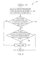
- Fig. 4 illustrates a flowchart of a process 40 according to an embodiment of the present invention.
- the process 40 is utilized for improving a buffer status triggering mechanism for a MAC layer of a UE and can be compiled into BSR triggering program code 350 shown in Fig. 3 .
- the process 40 includes the following steps:
- the UE determines if any data available for transmission other than the uplink data is included in a transmission buffer or not. If the transmission buffer is empty or includes no other data available for transmission, the BSR is triggered. If there is other data available for transmission in the transmission buffer, the UE determines if a logical channel corresponding to any data of the uplink data has higher priority than the data available for transmission in the transmission buffer or not. When the logical channel has higher priority, the BSR is triggered, otherwise no BSR is triggered. Preferably, the BSR is a regular BSR. Thus, the process 40 ensures that a BSR is triggered when the UE has data available for transmission.
- the uplink data is new or retransmission data that is in RLC or PDCP layers or has been received by the MAC layer.
- the uplink data corresponds to a single logical channel or comes from multiple logical channels at a certain TTI (Transmission Time Interval).
- the transmission buffer can be a buffer of an RLC or a PDCP transmission buffer.
- a regular BSR is triggered when the following two conditions are both met: (1) the UL data becomes available for transmission, and (2) when data of the UL data belongs to a logical channel with higher priority than those for which data available for transmission already existed in the transmission buffer if there is already data available for transmission other than the UL data in the UE transmission buffer.
- the process 40 can improve the problem of the issue 1 in the prior art.
- the RLC data PDU in the transmission buffer needs to be retransmitted, the RLC data PDU for retransmission becomes the above-defined data available for transmission, and then the UE determines if other data available for transmission in the transmission buffer or not. If the transmission buffer is empty or includes no other data available for transmission, the BSR for the retransmission of the RLC data PDU is triggered in order to request UL resources via the SR. On the contrary, if the transmission buffer includes other data available for transmission, the UE determines if logical channel priority of the RLC data PDU is higher than the data available for transmission or not. When the logical channel of the RLC data PDU has higher priority, the BSR is triggered, otherwise no BSR is triggered. Therefore, the retransmission of the RLC data PDU is not blocked when no UL resources are allocated.
- the process 40 can improve the problem of the issue 2 in the prior art.
- another UE RLC AM entity associated with a logical channel Y receives a SDU for transmission.
- the SDU of logical channel X in the transmission buffer is not considered the data available for transmission.
- the SDU of the logical channel Y is considered data available for transmission even the logical channel Y priority has lower priority than the logical channel X.
- the BSR is triggered and the uplink transmission for the SDU of the logical channel Y is not blocked.
- the data available for transmission, already existed in the UE transmission buffer before occurrence of the handover or the RRC connection re-establishment is determined as invisible data.
- the transmission buffer which includes only the data available for transmission existing before occurrence of the handover or the RRC connection re-establishment, is considered an empty transmission buffer at Step 404.
- the process 40 can improve the problem of the issue 4 in the prior art.
- the PDCP buffer includes data of the DRB that has been transmitted by RLC before but has not been acknowledged or negatively acknowledged before the radio link failure.
- the PDCP buffer is considered an empty buffer at Step 404 that is performed after the data of the RRC connection re-establishment complete message related to the SRB1 becomes data available for transmission.
- the BSR for the RRC connection re-establishment complete message is triggered even though the logical channel priority of SRB1 is lower than or equal to the logical channel priority of the DRB.
- the RRC connection re-establishment procedure can be performed successfully.
- a periodic BSR timer is maintained in the UE and used for triggering the periodic BSR.
- a periodic BSR is triggered, and then the periodic BSR timer is restarted.
- a process is provided as bellow to ensure that the BSR is able to be triggered when no UL resources are allocated and there is data available for transmission.
- Fig. 5 illustrates a flowchart of a process 50 according to an embodiment of the present invention.
- the process 50 is utilized for improving a buffer status triggering mechanism for a UE triggering a periodic BSR and can be compiled into the BSR triggering program code 350.
- the process 50 includes the following steps:
- the UE triggers the SR when having no UL resources allocated for new transmission for the TTI and there is uplink data becoming the data available for transmission defined as foregoing description.
- the SR can be triggered for requesting UL resources when the periodic BSR is triggered.
- the SR can be triggered not only when the UE has no UL resources allocated for new transmission for the TTI and has uplink data becoming the data available for transmission, but also when no MAC PDU, irrespective of including a BSR or not, is being retransmitted.
- the process 50 can improve the problem of the issues 1 and 2 of the prior art.
- the issues 1 and 2 of the prior art the uplink transmissions are blocked since no regular BSR can be transmitted.
- the issues 1 and 2 are possibly applied with the periodic BSR.
- the SR can be triggered when the UE has no UL resources allocated for new transmission and the RLC data PDU for retransmission becomes the above-defined data available for transmission.
- the process 50 is applied to the issue 2
- the SR can be triggered when the UE has no UL resources allocated for new transmission and the SDU of the logical channel Y is considered data available for transmission.
- the uplink transmissions related to the RLC data PDU for retransmission in the issue 1 and to the SDU of the logical channel Y are not blocked since the SR is triggered to request the eNB for UL resources.
- the SR can be triggered when the periodic BSR is triggered or the regular BSR is not triggered.
- FIG. 6 illustrates a flowchart of a process 60 according to an embodiment of the present invention.
- the process 60 is utilized for improving a buffer status triggering mechanism for a UE and can be compiled into the BSR triggering program code 350.
- the process 60 includes the following steps:
- the process 60 the PDCP packet becoming the data available for transmission is received in a PDCP layer, and thus the corresponding BSR is triggered.
- the UE determines the state of the RLC buffer.
- the transmitted PDCP packet is determined not to be the data available for transmission in the RLC layer.
- the transmitted PDCP packet is considered non-data available for transmission when the RLC buffer is empty or only includes data whose priority is lower than the PDCP packet. Therefore, the process 60 prevents the BSR related to the PDCP packet being triggered twice.
- the process 60 can improve the problem of the issues 3 of the prior art.
- the PDCP buffer and the RLC buffer are both empty, and then the PDCP entity receives a PDCP SDU considered the data available for transmission.
- the regular BSR for the PDCP layer is triggered and sent to the eNB.
- the PDCP entity After header compression and ciphering of the PDCP SDU, the PDCP entity generates a PDCP PDU and submits the PDCP PDU to the RLC entity.
- the PDCP PDU is considered non-data available for transmission in the RLC layer since the RLC buffer is empty.
- the BSR for the PDCP PDU is not triggered in the RLC layer.
- the BSR is not triggered twice.
- Fig. 7 illustrates a flowchart of a process 70 according to an embodiment of the present invention.
- the process 70 is utilized for improving a buffer status triggering mechanism for a UE and can be compiled into the BSR triggering program code 350.
- the process 70 includes the following steps:
- a BSR is triggered when the UE needs to transmit the RRC connection re-establishment complete message. Moreover, the BSR is triggered when no enough UL resource is assigned to transmit the RRC connection re-establishment complete message. In the situation where no UL resource is assigned, the BSR is triggered to trigger a SR.
- the BSR is a regular BSR.
- the BSR only includes SRB1 data available for transmission.
- the process 70 can improve the problem of the issue 4 of the prior art.
- the RRC connection re-establishment complete message needs to be transmitted, the RRC connection re-establishment complete message is not considered the data available for transmission since the SRB1 has priority lower than or equal to the DRB.
- the regular BSR is still triggered to trigger the SR for UL resources.
- FIG. 8 illustrates a flowchart of a process 80 according to an embodiment of the present invention.
- the process 80 is utilized for improving a buffer status triggering mechanism for a UE and can be compiled into the BSR triggering program code 350.
- the process 80 includes the following steps:
- the BSR for radio bearers other than the SRB 1 is triggered after the radio bearers are resumed.
- the UL resources can be assigned for the radio bearers.
- the radio bearers other than the SRB 1 are resumed by an RRC connection reconfiguration message of an RRC connection reconfiguration procedure.
- the BSR is a regular BSR including data available for transmission in the radio bearers other than the SRB1.
- Fig. 9 illustrates a flowchart of a process 90 according to an embodiment of the present invention.
- the process 90 is utilized for improving a buffer status triggering mechanism for a UE and can be compiled into the BSR triggering program code 350.
- the process 90 includes the following steps:
- the process 90 is a combination of concepts of the processes 70 and 80, and thus detailed description thereof is omitted herein.
- the process 90 can improve the problem of the issue 5 of the prior art.
- SRB 1 is resumed by an RRC connection re-establishment procedure, and other radio bearers, such as SRB2 and DRBs, can be resumed by a following RRC connection reconfiguration procedure.
- RRC connection re-establishment complete message needs to be transmitted, no radio bearers other than SRB 1 are resumed.
- a first regular BSR only including data available for transmission for the SRB1 is triggered according to the process 90.
- the embodiments of the present invention improve the BSR triggering mechanism to benefit performance of UL transmission and UL resource allocation.
Landscapes
- Engineering & Computer Science (AREA)
- Computer Networks & Wireless Communication (AREA)
- Signal Processing (AREA)
- Mobile Radio Communication Systems (AREA)
- Transceivers (AREA)
Abstract
Description
- The present invention relates to a method and apparatus for improving a buffer status triggering mechanism in a wireless communications system according to the pre-characterizing clauses of
claims 1 and 2. - As today's applications for electronic systems grow at ever-increasing rates, the demand for better communications performance is never ceasing. Standards for various technologies such as the 3rd Generation Partnership Project (3GPP) High-Speed Packet Access (HSPA) and Long Term Evolution (LTE) work towards creating more efficient communication systems.
- For example, dynamic resource allocation for uplink (UL) transmissions has been introduced in the a medium access control (MAC) layer standard, for communicating between a user equipment (UE) such as a mobile station or a mobile handset, and an Evolved Universal Terrestrial Radio Access Network (E-UTRAN) including evolved base stations (eNBs).
- Dynamic resource allocation utilizes radio resources more efficiently, where radio resources are allocated only when the UE has data to transmit. The E-UTRAN schedules UE transmission based on UE buffer status. The UE buffer status reporting has a great impact on efficiency of overall radio source usage arranged by E-UTRAN. Reporting more data volume than actual data volume in the buffer makes unnecessary uplink transmission and consumes UE power. Reporting less data volume than actual data volume in the buffer makes the UE inevitably request for more resources to be allocated and wait for the uplink resource allocation, and this causes a delay before the UE data can be transmitted, slowing down the overall communication between the UE and the E-UTRAN.
- In striving for faster and better communications and efficient usage of radio resource in our wireless communications systems, the unnecessary uplink resource allocation and uplink transmission delay should be alleviated.
- An RRC (Radio Resource Control) connection re-establishment procedure can be initiated by the UE to re-establish the RRC connection, which involves the resumption of SRB1 (Signaling Radio Bearer 1) and the re-activation of security. The UE shall only initiate the procedure when security has been activated. The UE initiates the procedure when one of the following conditions is met: (1) a radio link failure is detected; (2) upon handover failure; (3) the maximum number of retransmissions has been reached; (4) upon integrity failure indication from lower layers; (5) upon an RRC connection reconfiguration failure.
- Message exchange of the RRC connection re-establishment procedure between the UE and the EUTRAN is described below. The UE sends an RRC connection re-establishment request message to initiate the RRC connection re-establishment procedure. The EUTRAN transmits an RRC connection re-establishment message to accept the request. Finally, the UE responds with an RRC connection re-establishment complete message to notify the EUTRAN of the completion of the RRC connection re-establishment procedure.
- Through the RRC connection re-establishment procedure, the SRB1 can be resumed. For resumption of other radio bearers, such as SRB2 or DRBs (data radio bearers), an RRC connection re-configuration procedure is initiated following RRC connection re-establishment procedure. The RRC connection re-configuration procedure is initiated by the EUTRAN with an RRC connection re-configuration message, and an RRC connection re-configuration complete message is sent by the UE to complete the RRC connection re-configuration procedure.
- A buffer status reporting procedure is used for the UE to provide the serving eNB with information about the amount of data in the UL buffers of the UE. A Buffer Status Report (BSR) is defined as a MAC (Medium Access Control) Control Element and shall be triggered if any of the following conditions occur:
- (1) UL data becomes available for transmission in the RLC entity or in the PDCP entity and the data belongs to a logical channel with higher priority than those for which data already existed in the UE transmission buffer, in which case the BSR is referred below to as "Regular BSR";
- (2) UL resources are allocated and number of padding bits is equal to or larger than the size of the Buffer Status Report MAC control element, in which case the BSR is referred below to as "Padding BSR";
- (3) a serving cell change occurs, in which case the BSR is referred below to as "Regular BSR"; and
- (4) a PERIODIC BSR TIMER expires, in which case the BSR is referred below to as "Periodic BSR".
- As can be seen from the above, the BSR includes three types: Regular, Periodic and Padding types. In addition, the regular BSR is able to trigger a Scheduling Request (SR) for UL (Uplink) resources.
- Furthermore, according to the buffer status reporting procedure, a PERIODIC BSR TIMER is started when the regular BSR is sent. When the PERIODIC BSR TIMER expires, the periodic BSR is sent if there is UL resources for new transmission in this TTI (Transmission Time Interval). Otherwise, the periodic BSR is not sent. In this BSR triggering behavior, the regular BSR triggering condition affects operation of the PERIODIC BSR TIMER and thus is very important. As can be seen from the above, the regular BSR can be triggered by the conditions (1) and (3). The condition (1) is used for all necessary situations other than handover, whereas the condition (3) is only applied to handover.
- According to the condition (1), "the data belongs to a logical channel with higher priority than those for which data already existed in the UE transmission buffer" indicates that the UL data available for transmission needs to be compared with any data that has existed in the UE transmission buffer for logical channel priority. However, condition (1) causes an issue that no more BSR is triggered but there is still data available for transmission, which needs to be reported, in the UE transmission buffer.
- In addition, "UL data becomes available for transmission in the RLC entity or in the PDCP entity" quoted from the condition (1) can cause an issue that the UL data available for transmission is reported twice, resulting in space waste of the BSR.
- Four issues are described below with the current BSR triggering mechanism.
-
Issue 1 is described here. A UE RLC AM (Acknowledged Mode) entity associated with a logical channel receives a SDU (Service Data Unit) for transmission. Since the SDU for UL becomes available for transmission, a regular BSR is triggered according the abovementioned condition (1). Assume that no UL resources are allocated for new transmission for a TTI where the regular BSR is triggered. As a consequence, an SR is triggered and then sent. The eNB receives the SR and allocates a UL grant providing sufficient UL resources for SDU transmission. The UE receives the UL grant. The UE RLC AM entity constructs an RLC data PDU including this SDU. A poll bit is set in the RLC data PDU to request the eNB for ACK/NACK reporting, and thereby a POLL RETRANSMIT TIMER is started. The UE RLC AM entity submits the RLC data PDU to the MAC layer. The UE MAC constructs a MAC PDU including the RLC data PDU, also seen as a MAC SDU, and requests a PHY (Physical) layer to transmit. The MAC PDU transmission is failed. After a while, the POLL RETRANSMIT TIMER expires, indicating that the RLC data PDU in the transmission buffer needs to be retransmitted. However, according to the condition (1), no BSR is triggered because the RLC data PDU is already in the UE transmission buffer and furthermore, the RLC data PDU impossibly has higher priority than itself. As a result, the uplink data transmission is blocked since no BSR is triggered for the opportunity of UL resource allocating request (i.e. the SR). - Issue 2 is described here. A UE RLC AM entity associated with a logical channel X receives a SDU for transmission. According the condition (1), a regular BSR is triggered. When no UL resources allocated for new transmission for a TTI where the regular BSR is triggered, an SR is sent. The eNB receives the SR and thereby allocates a UL grant providing sufficient resources for SDU transmission with segmentation. After receiving the UL grant, the UE RLC AM entity constructs an RLC data PDU including this SDU. In addition, a poll bit is set in the RLC data PDU, and a POLL RETRANSMIT TIMER is started. The UE RLC AM entity submits the RLC data PDU to the MAC layer. The UE MAC constructs a MAC PDU and requests the PHY layer to transmit. Unfortunately the MAC PDU transmission is failed. Before the POLL RETRANSMIT TIMER expires, another UE RLC AM entity associated with a logical channel Y receives a SDU for transmission. Priority of the logical channel Y is lower than priority of the logical channel X. According to the condition (1), no BSR is triggered for the SDU of the logical channel Y because the RLC data PDU of the logical channel X has already been in the transmission buffer and the logical channel Y priority has lower priority than the logical channel X. As a result, the uplink data transmission for the SDU of the logical channel Y is blocked.
- Issue 3 is described here. A DRB (Data Radio Bearer) is configured with the PDCP entity and the RLC entity to transmit IP (Internet Protocol) packets. Assume that a PDCP buffer and an RLC buffer are both empty. The PDCP entity receives an IP packet (i.e. a PDCP SDU) from an IP layer. In this situation, the condition (1) is met because the PDCP data becomes available for transmission. As a result, a regular BSR is triggered. Assuming that UL resources are available, the MAC layer sends the regular BSR immediately. After header compression and ciphering of the PDCP SDU, the PDCP entity generates a PDCP PDU and submits the PDCP PDU to the RLC entity. In this situation, the condition (1) is met again because the RLC data becomes available for transmission. Thus, another regular BSR is triggered. Assuming that UL resources are available, the MAC layer sends a regular BSR again. As can be seen from the above, the regular BSR is triggered and sent twice for the same IP data, one time for the PDPC layer and the other time for the RLC layer. This increases overhead due to an unnecessary buffer status reporting.
- Issue 4 is described here. A UE has two logical channels, one for SRB1 and the other for a DRB, and initiates an RRC connection re-establishment procedure due to a radio link failure. When the UE receives an RRC connection re-establishment message, the UE shall send an RRC connection re-establishment complete message corresponding to SRB1. The UE has no UL grant to transmit the RRC connection re-establishment complete message, and the logical channel priority of SRB1 is lower than or equal to the logical channel priority of the DRB. Besides, the PDCP buffer includes data of the DRB that has been transmitted by RLC before but has not been acknowledged or negatively acknowledged before the radio link failure. In this case, no BSR is triggered according to the condition (1). As a result, the RRC connection re-establishment complete message cannot be transmitted. This causes failure of the RRC connection re-establishment procedure.
- Issue 5 is described here. At RRC connection re-establishment triggered by a radio link failure,
SRB 1 is resumed by an RRC connection re-establishment procedure, and other radio bearers, such as SRB2 and DRBs, are resumed by a following RRC connection reconfiguration procedure. If a regular BSR is triggered before any available radio bearers other thanSRB 1 are resumed, the regular BSR includes data available for transmission for all available radio bearers including SRB1 when the PDCP buffer includes data available for transmission related to the available radio bearers. However, it may be useless to provide buffer status of the radio bearers other than SRB1 with the regular BSR since the radio bearers are still suspended. The resources, which are allocated by the eNB for the suspended radio bearers, are wasted. Furthermore, in certain situations (e.g. a session ended by an application), some of the suspended radio bearers are possibly released by the following RRC connection reconfiguration procedure instead of being resumed. In this case, it is useless to include buffer status for the released radio bearers in the regular BSR. - This in mind, the present invention aims at providing a method and apparatus for improving a buffer status triggering mechanism, so as to solve the abovementioned problems.
- This is achieved by a method and apparatus for improving a buffer status triggering mechanism in a wireless communications system according to
claims 1 and 2. The dependent claims pertain to corresponding further developments and improvements. - As will be seen more clearly from the detailed description following below, the claimed method for improving a buffer status triggering mechanism of a communications layer for a mobile device of a wireless communication system triggering a buffer status report corresponding to a packet of a first communications layer when the packet of the first communications layer becomes data available for transmission in the first communications layer; when the packet of the first communications layer is transmitted to a second communications layer, determining whether a buffer of the second communications layer includes data whose priority is higher than the packet of the first communications layer; and when the buffer of the second communications layer does not include any data whose priority is higher than the packet of the first communications layer, determining that the packet of the first communications layer is not data available for transmission in the second communications layer.
-
- FIG. 1
- is a schematic diagram of a wireless communication system.
- FIG. 2
- is a schematic diagram of a communication device according to embodiments of the present invention.
- FIG. 3
- is a schematic diagram of the program code according to
Fig. 2 . - FIGs.
- 4-9 are flowcharts of processes according to embodiments of the present invention.
- Please refer to
Fig. 1 , which illustrates a schematic diagram of awireless communication system 10 according to an embodiment of the present invention. Thewireless communication system 10 is briefly composed of a network and a plurality of mobile devices. InFig. 1 , the network and the mobile devices are simply utilized for illustrating the structure of thewireless communication system 10. Preferably, thewireless communication system 10 is an LTE (long-term evolution) system. In the LTE system, the network is referred as an evolved base station (eNB) or a EUTRAN (evolved-UTAN) comprising a plurality of eNBs, whereas the mobile devices are referred as user equipments (UEs). The UEs can be devices such as mobile phones, computer systems, etc. Besides, the network and the UE can be seen as a transmitter or receiver according to transmission direction, e.g., for uplink (UL), the UE is the transmitter and the network is the receiver, and for downlink, the network is the transmitter and the UE is the receiver. - Please refer to
Fig. 2 , which illustrates a schematic diagram of acommunication device 20 according to an embodiment of the present invention. Thecommunication device 20 can be the mobile devices (UEs in the LTE system) shown inFig. 1 and includes aprocessor 200, a computerreadable recording medium 210, acommunication interfacing unit 220 and acontrol unit 230. The computerreadable recording medium 210 is any data storage device that storesstorage data 212, includingprogram code 214, thereafter read and processed by theprocessor 200. Examples of the computerreadable recording medium 210 include a subscriber identity module (SIM), read-only memory (ROM), random-access memory (RAM), CD-ROMs, magnetic tapes, floppy disks, optical data storage devices, and carrier waves (such as data transmission through the Internet). Thecontrol unit 230 controls thecommunication interfacing unit 220 and related operations and states of thecommunication device 20 according to processing results of theprocess 200. Thecommunication interfacing unit 220 is preferably a radio transceiver for wirelessly communicating with the network. - Please refer to
Fig. 3 , which illustrates a schematic diagram of theprogram code 214 for the LTE system according to an embodiment of the present invention. Theprogram code 214 includes program code of multiple communications protocol layers, which from top to bottom are a radio resource control (RRC)layer 300, a packet data convergence protocol (PDCP)layer 310, a radio link control (RLC)layer 320, a medium access control (MAC)layer 330 and a physical (PHY)layer 340. TheRRC layer 300 and theRLC layer 320 can establish an RRC connection and an RLC link with the network. According to the communication quality requirement and configuration indicated by the network, theRRC layer 300 is used for performing RRC connection establishment, re-establishment, reconfiguration, or other RRC procedures. TheRRC layer 300 is responsible for generating or releasing radio bearers (RBs) including data RBs (DRBs) and signaling RBs (SRBs). SRB data has higher, equal or lower priority than DRB data depended on system requirement. - The
RLC layer 320 is used for performing RLC reset or RLC re-establishment. Furthermore, theRLC layer 320 is able to process RLC SDUs (Service Data Units), RLC data PDUs (Protocol Data Units), RLC control PDUs, STATUS PDUs including ACKs (Acknowledgements) or NACKs (Negative Acknowledgements), or segments of the foregoing RLC PDUs. - The
MAC layer 330 is used for triggering and transmitting a buffer status report (BSR) including buffer states of theRLC layer 320 and thePDCP layer 310. The BSR includes three types: Regular, Periodic and Padding types. Data that shall be included in the buffer status report is hereinafter called data available for transmission including the following types. - For the
RLC layer 320, the following data is considered the data available for transmission: RLC SDUs (Service Data Units), or segments thereof, that have not yet been included in an RLC data PDU or RLC data PDUs, or portions thereof, that are pending for retransmission in an AM (Acknowledged Mode); and - a STATUS PDU that attempts to be transmitted in the next transmission opportunity, if the STATUS PDU has been triggered and a status prohibit timer is not running or has expired.
- Please note that the RLC SDUs pending for retransmission herein mean that data of the RLC SDUs are used in a following retransmission. Preferably, the RLC SDUs are still retransmitted in RLC PDU or RLC PDU segment form.
- For the
PDCP layer 310 without occurrence of a handover, the following data is considered the data available for transmission: - the PDCP SDUs for which no PDCP PDU has been submitted to lower layers.
- More specifically, the data available for transmission includes:
- the abovementioned PDCP SDUs, if the PDCP SDU has not yet been processed by the
PDCP layer 310, or - a PDCP control or data PDU if the PDCP SDU has been processed by the
PDCP layer 310. - In addition, for radio bearers mapped on the AM of the
RLC layer 320, if thePDCP layer 310 has previously received an indication indicating that a handover or a RRC connection re-establishment has occurred, the following data is considered the data available for transmission for the PDCP layer 310: - For PDCP SDUs for which a corresponding PDU has only been submitted to lower layers before the
PDCP layer 310 has received an indication that a handover or a RRC connection re-establishment has occurred, and for which the successful delivery has not been confirmed by lower layers (e.g. the RLC layer 320) or by a PDCP status report. - More specifically, the data available for transmission includes:
- the PDCP SDU that has not yet been processed by the
PDCP layer 310, or - the PDCP data PDU that once has been processed by the
PDCP layer 310. - All data available for transmission for BSRs in the following processes are defined as the abovementioned data available for transmission.
- Please refer to
Fig. 4 , which illustrates a flowchart of aprocess 40 according to an embodiment of the present invention. Theprocess 40 is utilized for improving a buffer status triggering mechanism for a MAC layer of a UE and can be compiled into BSR triggeringprogram code 350 shown inFig. 3 . Theprocess 40 includes the following steps: - Step 400:
- Start.
- Step 402:
- Receive an indication indicating that uplink data becomes data available for
- Step 404:
- transmission in an upper layer. Determine if any data available for transmission other than the uplink data is included in a transmission buffer of the upper layer or not. If so, perform
Step 406; if not, performStep 408. - Step 406:
- Determine if a logical channel corresponding to any data of the uplink data has higher priority than the data available for transmission in the transmission buffer or not. If so, perform
Step 408; if not, performStep 410. - Step 408:
- Trigger a BSR.
- Step 410:
- End.
- According to the
process 40, when the UE is aware that the uplink data becomes available for transmission, the UE determines if any data available for transmission other than the uplink data is included in a transmission buffer or not. If the transmission buffer is empty or includes no other data available for transmission, the BSR is triggered. If there is other data available for transmission in the transmission buffer, the UE determines if a logical channel corresponding to any data of the uplink data has higher priority than the data available for transmission in the transmission buffer or not. When the logical channel has higher priority, the BSR is triggered, otherwise no BSR is triggered. Preferably, the BSR is a regular BSR. Thus, theprocess 40 ensures that a BSR is triggered when the UE has data available for transmission. - Preferably, the uplink data is new or retransmission data that is in RLC or PDCP layers or has been received by the MAC layer. In addition, the uplink data corresponds to a single logical channel or comes from multiple logical channels at a certain TTI (Transmission Time Interval). In this situation, the transmission buffer can be a buffer of an RLC or a PDCP transmission buffer.
- As can be seen from the
process 40, a regular BSR is triggered when the following two conditions are both met: (1) the UL data becomes available for transmission, and (2) when data of the UL data belongs to a logical channel with higher priority than those for which data available for transmission already existed in the transmission buffer if there is already data available for transmission other than the UL data in the UE transmission buffer. - The
process 40 can improve the problem of theissue 1 in the prior art. When the RLC data PDU in the transmission buffer needs to be retransmitted, the RLC data PDU for retransmission becomes the above-defined data available for transmission, and then the UE determines if other data available for transmission in the transmission buffer or not. If the transmission buffer is empty or includes no other data available for transmission, the BSR for the retransmission of the RLC data PDU is triggered in order to request UL resources via the SR. On the contrary, if the transmission buffer includes other data available for transmission, the UE determines if logical channel priority of the RLC data PDU is higher than the data available for transmission or not. When the logical channel of the RLC data PDU has higher priority, the BSR is triggered, otherwise no BSR is triggered. Therefore, the retransmission of the RLC data PDU is not blocked when no UL resources are allocated. - The
process 40 can improve the problem of the issue 2 in the prior art. After the failure of the MAC PDU related to the SDU of logical channel X and before expiration of the POLL RETRANSMIT TIMER, another UE RLC AM entity associated with a logical channel Y receives a SDU for transmission. According to theprocess 40, the SDU of logical channel X in the transmission buffer is not considered the data available for transmission. In this situation, the SDU of the logical channel Y is considered data available for transmission even the logical channel Y priority has lower priority than the logical channel X. As a result, the BSR is triggered and the uplink transmission for the SDU of the logical channel Y is not blocked. - For the
process 40 applied to the situations where a handover or a RRC connection re-establishment occurs, atStep 404, the data available for transmission, already existed in the UE transmission buffer before occurrence of the handover or the RRC connection re-establishment, is determined as invisible data. In other words, the transmission buffer, which includes only the data available for transmission existing before occurrence of the handover or the RRC connection re-establishment, is considered an empty transmission buffer atStep 404. - In this situation, the
process 40 can improve the problem of the issue 4 in the prior art. During the RRC connection re-establishment procedure, the PDCP buffer includes data of the DRB that has been transmitted by RLC before but has not been acknowledged or negatively acknowledged before the radio link failure. According to theprocess 40, the PDCP buffer is considered an empty buffer atStep 404 that is performed after the data of the RRC connection re-establishment complete message related to the SRB1 becomes data available for transmission. In this situation, the BSR for the RRC connection re-establishment complete message is triggered even though the logical channel priority of SRB1 is lower than or equal to the logical channel priority of the DRB. Thus, the RRC connection re-establishment procedure can be performed successfully. - A periodic BSR timer is maintained in the UE and used for triggering the periodic BSR. When the periodic BSR timer expires, a periodic BSR is triggered, and then the periodic BSR timer is restarted. In this situation, a process is provided as bellow to ensure that the BSR is able to be triggered when no UL resources are allocated and there is data available for transmission. Please refer to
Fig. 5 , which illustrates a flowchart of aprocess 50 according to an embodiment of the present invention. Theprocess 50 is utilized for improving a buffer status triggering mechanism for a UE triggering a periodic BSR and can be compiled into the BSR triggeringprogram code 350. Theprocess 50 includes the following steps: - Step 500:
- Start.
- Step 502:
- Trigger a scheduling request corresponding to the periodic BSR when the UE has no UL resources allocated for new transmission for a TTI and has uplink data becoming data available for transmission.
- Step 504:
- End.
- According to the
process 50 where the periodic BSR is triggered, the UE triggers the SR when having no UL resources allocated for new transmission for the TTI and there is uplink data becoming the data available for transmission defined as foregoing description. Thus, through theprocess 50, the SR can be triggered for requesting UL resources when the periodic BSR is triggered. - Preferably, the SR can be triggered not only when the UE has no UL resources allocated for new transmission for the TTI and has uplink data becoming the data available for transmission, but also when no MAC PDU, irrespective of including a BSR or not, is being retransmitted.
- The
process 50 can improve the problem of theissues 1 and 2 of the prior art. In theissues 1 and 2 of the prior art, the uplink transmissions are blocked since no regular BSR can be transmitted. However, theissues 1 and 2 are possibly applied with the periodic BSR. When theprocess 50 is applied to theissue 1, the SR can be triggered when the UE has no UL resources allocated for new transmission and the RLC data PDU for retransmission becomes the above-defined data available for transmission. On the other hand, when theprocess 50 is applied to the issue 2, the SR can be triggered when the UE has no UL resources allocated for new transmission and the SDU of the logical channel Y is considered data available for transmission. - Thus, the uplink transmissions related to the RLC data PDU for retransmission in the
issue 1 and to the SDU of the logical channel Y are not blocked since the SR is triggered to request the eNB for UL resources. - In the prior art, only the regular BSR is able to trigger the SR. In the embodiment of the present invention, the SR can be triggered when the periodic BSR is triggered or the regular BSR is not triggered.
- Please refer to
Fig. 6 , which illustrates a flowchart of aprocess 60 according to an embodiment of the present invention. Theprocess 60 is utilized for improving a buffer status triggering mechanism for a UE and can be compiled into the BSR triggeringprogram code 350. Theprocess 60 includes the following steps: - Step 600:
- Start.
- Step 602:
- Receive a PDCP packet becoming data available for transmission in a PDCP layer.
- Step 604:
- Trigger and send a BSR for the PDCP layer.
- Step 606:
- Transmit the PDCP packet to an RLC buffer for new transmission.
- Step 608:
- Determine if the RLC buffer includes data whose priority is higher than the PDCP packet or not. If so, perform
Step 612; if not, performStep 610. □ - Step 610:
- Determine that the transmitted PDCP packet is not data available for transmission in the RLC layer.
- Step 612:
- End.
- According to the
process 60, the PDCP packet becoming the data available for transmission is received in a PDCP layer, and thus the corresponding BSR is triggered. When the PDCP packet is transmitted to an RLC buffer for new transmission, the UE determines the state of the RLC buffer. When the RLC buffer does not include any data whose priority is higher than the PDCP packet, the transmitted PDCP packet is determined not to be the data available for transmission in the RLC layer. In other words, the transmitted PDCP packet is considered non-data available for transmission when the RLC buffer is empty or only includes data whose priority is lower than the PDCP packet. Therefore, theprocess 60 prevents the BSR related to the PDCP packet being triggered twice. - The
process 60 can improve the problem of the issues 3 of the prior art. As having been known from the above, the PDCP buffer and the RLC buffer are both empty, and then the PDCP entity receives a PDCP SDU considered the data available for transmission. In this situation, the regular BSR for the PDCP layer is triggered and sent to the eNB. After header compression and ciphering of the PDCP SDU, the PDCP entity generates a PDCP PDU and submits the PDCP PDU to the RLC entity. According to theprocess 60, the PDCP PDU is considered non-data available for transmission in the RLC layer since the RLC buffer is empty. Thus, the BSR for the PDCP PDU is not triggered in the RLC layer. The BSR is not triggered twice. - Please refer to
Fig. 7 , which illustrates a flowchart of aprocess 70 according to an embodiment of the present invention. Theprocess 70 is utilized for improving a buffer status triggering mechanism for a UE and can be compiled into the BSR triggeringprogram code 350. Theprocess 70 includes the following steps: - Step 700:
- Start.
- Step 702:
- Initiate an RRC connection re-establishment procedure.
- Step 704:
- Trigger a BSR when an RRC connection re-establishment complete message of the RRC connection re-establishment procedure needs to be transmitted.
- Step 706:
- End.
- According to the
process 70, after initiation of the RRC connection re-establishment procedure, a BSR is triggered when the UE needs to transmit the RRC connection re-establishment complete message. Moreover, the BSR is triggered when no enough UL resource is assigned to transmit the RRC connection re-establishment complete message. In the situation where no UL resource is assigned, the BSR is triggered to trigger a SR. - Through the
process 70, uplink transmission related to the RRC connection re-establishment complete message is not blocked when no UL resources are assigned. Thus, failure of the RRC connection re-establishment procedure is avoided. - Preferably, the BSR is a regular BSR. The BSR only includes SRB1 data available for transmission.
- The
process 70 can improve the problem of the issue 4 of the prior art. When the RRC connection re-establishment complete message needs to be transmitted, the RRC connection re-establishment complete message is not considered the data available for transmission since the SRB1 has priority lower than or equal to the DRB. However, with theprocess 70, the regular BSR is still triggered to trigger the SR for UL resources. - Please refer to
Fig. 8 , which illustrates a flowchart of aprocess 80 according to an embodiment of the present invention. Theprocess 80 is utilized for improving a buffer status triggering mechanism for a UE and can be compiled into the BSR triggeringprogram code 350. Theprocess 80 includes the following steps: - Step 800:
- Start.
- Step 802:
- Trigger a BSR for radio bearers other than a
SRB 1 after the radio bearers other thanSRB 1 are resumed. - Step 804:
- End.
- According to the
process 80, the BSR for radio bearers other than theSRB 1 is triggered after the radio bearers are resumed. Thus, the UL resources can be assigned for the radio bearers. - Preferably, the radio bearers other than the
SRB 1 are resumed by an RRC connection reconfiguration message of an RRC connection reconfiguration procedure. The BSR is a regular BSR including data available for transmission in the radio bearers other than the SRB1. - Please refer to
Fig. 9 , which illustrates a flowchart of aprocess 90 according to an embodiment of the present invention. Theprocess 90 is utilized for improving a buffer status triggering mechanism for a UE and can be compiled into the BSR triggeringprogram code 350. Theprocess 90 includes the following steps: - Step 900:
- Start.
- Step 902:
- Initiate an RRC connection re-establishment procedure.
- Step 904:
- When an RRC connection re-establishment complete message of the RRC connection re-establishment procedure needs to be transmitted, trigger a first BSR only including only data available for transmission corresponding to a SRB1.
- Step 906:
- Perform an RRC connection reconfiguration procedure for resumption of radio bearers other than the SRB1.
- Step 908:
- Trigger a second BSR for the radio bearers other than a
SRB 1 after the radio bearers other thanSRB 1 are resumed by the RRC connection reconfiguration procedure. - Step 910:
- End.
- As can been seen from the above, the
process 90 is a combination of concepts of theprocesses - The
process 90 can improve the problem of the issue 5 of the prior art. At RRC connection re-establishment triggered by a radio link failure,SRB 1 is resumed by an RRC connection re-establishment procedure, and other radio bearers, such as SRB2 and DRBs, can be resumed by a following RRC connection reconfiguration procedure. When the RRC connection re-establishment complete message needs to be transmitted, no radio bearers other thanSRB 1 are resumed. In this situation, a first regular BSR only including data available for transmission for the SRB1 is triggered according to theprocess 90. - After the RRC connection reconfiguration procedure is performed, some of the radio bearers other than SRB1 are resumed, and some are released. In this situation, a second BSR for the radio bearers other than a
SRB 1 is triggered. Thus, with theprocess 90, no redundant data available for transmission is included in the first regular BSR. - In conclusion, the embodiments of the present invention improve the BSR triggering mechanism to benefit performance of UL transmission and UL resource allocation.
- For the sake of completeness, the invention is further described based on the following clauses:
- 1. A method for improving a buffer status triggering mechanism of a communications layer for a mobile device of a wireless communication system (10), characterized by the method comprising:
- receiving an indication indicating that uplink data becomes data available for transmission in an upper layer of the communications layer;
- when data available for transmission other than the uplink data is included in a transmission buffer of the upper layer, determining whether a logical channel corresponding to any data of the uplink data has higher priority than logical channels corresponding to the data available for transmission in the transmission buffer; and
- when the logical channel corresponding to any data of the uplink data has higher priority than the logical channels corresponding to the data available for transmission in the transmission buffer, triggering a buffer status report.
- 2. A communication device (20) of a wireless communication system (10) for improving a buffer status triggering mechanism of a communications layer, the communication device (20) comprising:
- a computer readable recording medium (210) for storing program code (214) corresponding to a process (40);
- a processor (200) coupled to the computer readable recording medium (210), for processing the program code (214) to execute the process (40);
- wherein the process (40) comprises:
receiving an indication indicating that uplink data becomes data available for transmission in an upper layer of the communications layer;
when data available for transmission other than the uplink data is included in a transmission buffer of the upper layer, determining whether a logical channel corresponding to any data of the uplink data has higher priority than logical channels corresponding to the data available for transmission in the transmission buffer; and
when the logical channel corresponding to any data of the uplink data has higher priority than the logical channels corresponding to the data available for transmission in the transmission buffer, triggering a buffer status report. - 3. The method of
clause 1 characterized by:- determining whether any data available for transmission other than the uplink data is included in the transmission buffer of the upper layer; and
- when no data available for transmission other than the uplink data is included in the transmission buffer of the upper layer, triggering the buffer status report, or the communication device (20) of clause 2, characterized in that the process (40) further comprises:
- determining whether any data available for transmission other than the uplink data is included in the transmission buffer of the upper layer; and
- when no data available for transmission other than the uplink data is included in the transmission buffer of the upper layer, triggering the buffer status report.
- 4. The method of
clause 1 characterized by determining data available for transmission already included in the transmission buffer before a handover or a radio resource control connection re-establishment occurs as invisible data when the handover or the radio resource control connection re-establishment occurs, or the communication device (20) of clause 2, characterized in that the process (40) further comprises determining data available for transmission already included in the transmission buffer before a handover or a radio resource control connection re-establishment occurs as invisible data when the handover or the radio resource control connection re-establishment occurs - 5. The method of
claim 1 or the communication device (20) of clause 2, characterized in that the communications layer is a medium access control layer (330), and the upper layer is a radio link control (320), hereinafter called RLC, layer or a packet data convergence protocol hereinafter called PDCP, layer (310). - 6. The method or the communication device (20) of clause 5, characterized in that the data available for transmission for the RLC layer (320) comprises at least one of:
- RLC SDUs, known as service data units, that have not yet been included in an RLC data PDU, known as protocol data units, or are pending for retransmission;
- segments of RLC SDUs that have not yet been included in an RLC data PDU or are pending for retransmission; and
- a STATUS PDU arranged to be transmitted in next transmission opportunity when the STATUS PDU has been triggered and a status prohibit timer is not running or has expired; and
the data available for transmission for the PDCP layer (310) comprises at least one of: - PDCP control PDUs;
- PDCP SDUs, known as service data units, for which no PDCP PDU, known as protocol data units, has been submitted to the RLC layer (320); and
- when an indication indicating that a handover or a RRC (Radio Resource Control) connection re-establishment has occurred is received, PDCP SDUs for which a corresponding PDCP PDU has only been submitted to the RLC layer (320) before the indication is received, and for which a successful delivery has not been confirmed by the RLC layer (320) or MAC layer (330) or by a PDCP status report.
- 7. A method for improving a buffer status triggering mechanism for a mobile device triggering a buffer status report in a wireless communication system (10), characterized by the method comprising:
- triggering a scheduling request corresponding to the buffer status report when the mobile device has no uplink resources allocated for a new transmission and has uplink data becoming data available for transmission.
- 8. A communication device (20) of a wireless communication system (10) for improving a buffer status triggering mechanism where a buffer status report is triggered, the communication device (20) comprising:
- a computer readable recording medium (210) for storing program code (214) corresponding to a process (50); and
- a processor (200) coupled to the computer readable recording medium (210), for processing the program code (214) to execute the process (50);
characterized by
triggering a scheduling request corresponding to the buffer status report when the communication device (20) has no uplink resources allocated for a new transmission and has uplink data becoming data available for transmission. - 9. The method of clause 7 or the communication device (20) of clause 8, characterized in that the buffer status report is a periodic buffer status report.
- 10. The method of clause or the communication device (20) of clause 8, characterized in that the data available for transmission comprises at least one of:
- RLC SDUs, known as radio link control service data units, that have not yet been included in an RLC data PDU, known as protocol data units, or are pending for retransmission;
- segments of RLC SDUs that have not yet been included in an RLC data PDU or are pending for retransmission;
- a STATUS PDU arranged to be transmitted in next transmission opportunity when the STATUS PDU has been triggered and a status prohibit timer is not running or has expired;
- PDCP control PDUs;
- PDCP SDUs, known as packet data convergence protocol service data units, for which no PDCP PDU, known as protocol data units, has been submitted to the RLC layer (320); and
- when an indication indicating that a handover or a RRC (Radio Resource Control) connection re-establishment has occurred is received, PDCP SDUs for which a corresponding PDCP PDU has only been submitted to the RLC layer (320) before the indication is received, and for which a successful delivery has not been confirmed by the RLC layer (320) or MAC layer (330) or by a PDCP status report.
- 11. The method of clause 7, characterized in that triggering the scheduling request corresponding to the buffer status report when the mobile device has no uplink resources allocated for the new transmission and has uplink data becoming data available for transmission is triggering the scheduling request corresponding to the buffer status report when the mobile device has no uplink resources allocated for the new transmission, has no medium access control packet retransmitted, and has uplink data becoming data available for transmission, or the communication device (20) of clause 8, characterized in that triggering the scheduling request corresponding to the buffer status report when the communication device (20) has no uplink resources allocated for the new transmission and has uplink data becoming data available for transmission is triggering the scheduling request corresponding to the buffer status report when the mobile device has no uplink resources allocated for the new transmission, has no medium access control packet retransmitted, and has uplink data becoming data available for transmission.
- 12. A method for improving a buffer status triggering mechanism for a mobile device of a wireless communication system (10), characterized by the method comprising:
- triggering a buffer status report corresponding to a packet of a first communications layer when the packet of the first communications layer becomes data available for transmission in the first communications layer;
- when the packet of the first communications layer is transmitted to a second communications layer, determining whether a buffer of the second communications layer includes data whose priority is higher than the packet of the first communications layer; and
- when the buffer of the second communications layer does not include any data whose priority is higher than the packet of the first communications layer, determining that the packet of the first communications layer is not data available for transmission in the second communications layer.
- 13. A communication device (20) of a wireless communication system (10) for improving a buffer status triggering mechanism, the communication device (20) comprising:
- a computer readable recording medium (210) for storing program code (214) corresponding to a process (60);
- a processor (200) coupled to the computer readable recording medium (210), for processing the program code (214) to execute the process (60);
- wherein the process (60) comprises:
triggering a buffer status report corresponding to a packet of a first communications layer when the packet of the first communications layer becomes data available for transmission in the first communications layer;
when the packet of the first communications layer is transmitted to a second communications layer, determining whether a buffer of the second communications layer includes data whose priority is higher than the packet of the first communications layer; and
when the buffer of the second communications layer does not include any data whose priority is higher than the packet of the first communications layer, determining that the packet of the first communications layer is not data available for transmission in the second communications layer. - 14. The method of clause 12 or the communication device (20) of clause 13, characterized in that the first communications layer is a packet data convergence protocol hereinafter called PDCP, layer (310), and the second communications layer is a radio link control, hereinafter called RLC, layer (320).
- 15. The method or the communication device (20) of clause 14 , characterized in that the data available for transmission in the PDCP layer (310) comprises at least one of:
- PDCP SDUs, known as service data units, for which no PDCP PDU, known as protocol data units, has been submitted to the RLC layer (320); and
- when an indication indicating that a handover or a RRC (Radio Resource Control) connection re-establishment has occurred is received, PDCP SDUs for which a corresponding PDCP PDU has only been submitted to the RLC layer (320) before the indication is received, and for which a successful delivery has not been confirmed by the RLC layer (320) or MAC layer (330) or by a PDCP status report; and
the data available for transmission in the RLC layer (320) comprises at least one of: - RLC SDUs, known as service data units, that have not yet been included in an RLC data PDU, known as protocol data units, or are pending for retransmission;
- segments of RLC SDUs that have not yet been included in an RLC data PDU or are pending for retransmission; and
- a STATUS PDU arranged to be transmitted in next transmission opportunity when the STATUS PDU has been triggered and a status prohibit timer is not running or has expired.
- 16. A method for improving a buffer status triggering mechanism for a mobile device of a wireless communication system (10), characterized by the method comprising:
- initiating a radio resource control, hereinafter called RRC, connection re-establishment procedure; and
- when an RRC connection re-establishment complete message of the RRC connection re-establishment procedure needs to be transmitted, triggering a buffer status report corresponding to the RRC connection re-establishment complete message.
- 17. A communication device (20) of a wireless communication system (10) for improving a buffer status triggering mechanism, the communication device (20) comprising:
- a computer readable recording medium (210) for storing program code (214) corresponding to a process (70);
- a processor (200) coupled to the computer readable recording medium (210), for processing the storage data to execute the process (70);
characterized by
initiating an radio resource control, hereinafter called RRC, connection re-establishment procedure; and
when an RRC connection re-establishment complete message of the RRC connection re-establishment procedure needs to be transmitted, triggering a buffer status report corresponding to the RRC connection re-establishment complete message. - 18. The method of clause 16 or the communication device (20) of clause 17, characterized in that the buffer status report corresponding to the RRC connection re-establishment complete message only comprises data available for transmission corresponding to a
signaling radio bearer 1, known as SRB1, and the data available for transmission comprises at least one of:- RLC SDUs, known as radio link control service data units, that have not yet been included in an RLC data PDU, known as protocol data units, or are pending for retransmission;
- segments of RLC SDUs that have not yet been included in an RLC data PDU or are pending for retransmission;
- a STATUS PDU arranged to be transmitted in next transmission opportunity when the STATUS PDU has been triggered and a status prohibit timer is not running or has expired;
- PDCP control PDUs;
- PDCP SDUs, known as packet data convergence protocol service data units, for which no PDCP PDU, known as protocol data units, has been submitted to the RLC layer (320); and
- when an indication indicating that a handover or a RRC (Radio Resource Control) connection re-establishment has occurred is received, PDCP SDUs for which a corresponding PDCP PDU has only been submitted to the RLC layer (320) before the indication is received, and for which a successful delivery has not been confirmed by the RLC layer (320) or MAC layer (330) or by a PDCP status report.
- 19. The method of clause 16 or the communication device (20) of clause 17, characterized in that triggering the buffer status report when the RRC connection re-establishment complete message needs to be transmitted is triggering the buffer status report when the RRC connection re-establishment complete message needs to be transmitted and no uplink resources corresponding to the RRC connection re-establishment complete message is allocated.
- 20. The method or the communication device (20) of clause 19 characterized by triggering a scheduling request by the buffer status report.
- 21. A method for improving a buffer status triggering mechanism for a mobile device of a wireless communication system (10), characterized by the method comprising:
- triggering a buffer status report for radio bearers other than a
signaling radio bearer 1 after the radio bearers other than the signalingradio bearer 1 are resumed.
- triggering a buffer status report for radio bearers other than a
- 22. A communication device (20) of a wireless communication system (10) for improving a buffer status triggering mechanism, the communication device (20) comprising:
- a computer readable recording medium (210) for storing program code (214) corresponding to a process (90);
- a processor (200) coupled to the computer readable recording medium (210), for processing the program code (214) to execute the process (90);
- wherein the process (90) comprises:
- triggering a buffer status report for radio bearers other than a
signaling radio bearer 1 after the radio bearers other than the signalingradio bearer 1 are resumed.
- triggering a buffer status report for radio bearers other than a
- 23. The method of clause 21 or the communication device (20) of clause 22, characterized in that the radio bearers other than the signaling
radio bearer 1 are resumed by a radio resource control connection reconfiguration procedure. - 24. The method of clause 21 or the communication device (20) of clause 22, characterized in that the buffer status report comprises data available for transmission corresponding to the radio bearers other than the signaling
radio bearer 1, and the data available for transmission comprises at least one of:- RLC SDUs, known as radio link control service data units, that have not yet been included in an RLC data PDU, known as protocol data units, or are pending for retransmission;
- segments of RLC SDUs that have not yet been included in an RLC data PDU or are pending for retransmission;
- a STATUS PDU arranged to be transmitted in next transmission opportunity when the STATUS PDU has been triggered for the SRB1 and a status prohibit timer is not running or has expired;
- PDCP SDUs, known as packet data convergence protocol service data units, for which no PDCP PDU, known as protocol data units, has been submitted to the RLC layer (320); and
Claims (4)
- A method for improving a buffer status triggering mechanism for a mobile device of a wireless communication system (10), characterized by the method comprising:triggering a buffer status report corresponding to a packet of a first communications layer when the packet of the first communications layer becomes data available for transmission in the first communications layer;when the packet of the first communications layer is transmitted to a second communications layer, determining whether a buffer of the second communications layer includes data whose priority is higher than the packet of the first communications layer; andwhen the buffer of the second communications layer does not include any data whose priority is higher than the packet of the first communications layer, determining that the packet of the first communications layer is not data available for transmission in the second communications layer.
- A communication device (20) of a wireless communication system (10) for improving a buffer status triggering mechanism, the communication device (20) comprising:a computer readable recording medium (210) for storing program code (214) corresponding to a process (60);a processor (200) coupled to the computer readable recording medium (210), for processing the program code (214) to execute the process (60);wherein the process (60) comprises:
characterized bytriggering a buffer status report corresponding to a packet of a first communications layer when the packet of the first communications layer becomes data available for transmission in the first communications layer;when the packet of the first communications layer is transmitted to a second communications layer, determining whether a buffer of the second communications layer includes data whose priority is higher than the packet of the first communications layer; andwhen the buffer of the second communications layer does not include any data whose priority is higher than the packet of the first communications layer, determining that the packet of the first communications layer is not data available for transmission in
the second communications layer. - The method of claim 1 or the communication device (20) of claim 2, characterized in that the first communications layer is a packet data convergence protocol hereinafter called PDCP, layer (310), and the second communications layer is a radio link control, hereinafter called RLC, layer (320).
- The method or the communication device (20) of claim 3 , characterized in that the data available for transmission in the PDCP layer (310) comprises at least one of:PDCP SDUs, known as service data units, for which no PDCP PDU, known as protocol data units, has been submitted to the RLC layer (320); andwhen an indication indicating that a handover or a RRC (Radio Resource Control) connection re-establishment has occurred is received, PDCP SDUs for which a corresponding PDCP PDU has only been submitted to the RLC layer (320) before the indication is received, and for which a successful delivery has not been confirmed by the RLC layer (320) or MAC layer (330) or by a PDCP status report; and
the data available for transmission in the RLC layer (320) comprises at least one of:RLC SDUs, known as service data units, that have not yet been included in an RLC data PDU, known as protocol data units, or are pending for retransmission;segments of RLC SDUs that have not yet been included in an RLC data PDU or are pending for retransmission; anda STATUS PDU arranged to be transmitted in next transmission opportunity when the STATUS PDU has been triggered and a status prohibit timer is not running or has expired.
Applications Claiming Priority (3)
| Application Number | Priority Date | Filing Date | Title |
|---|---|---|---|
| US9918008P | 2008-09-22 | 2008-09-22 | |
| US12/554,928 US8254333B2 (en) | 2008-09-22 | 2009-09-07 | Method for improving buffer status triggering mechanism in wireless communications system and related communication device |
| EP09011880.3A EP2166691B1 (en) | 2008-09-22 | 2009-09-17 | Methods and apparatuses for improving buffer status triggering mechanism in wireless communictions system |
Related Parent Applications (2)
| Application Number | Title | Priority Date | Filing Date |
|---|---|---|---|
| EP09011880.3 Division | 2009-09-17 | ||
| EP09011880.3A Division-Into EP2166691B1 (en) | 2008-09-22 | 2009-09-17 | Methods and apparatuses for improving buffer status triggering mechanism in wireless communictions system |
Publications (2)
| Publication Number | Publication Date |
|---|---|
| EP2227053A1 true EP2227053A1 (en) | 2010-09-08 |
| EP2227053B1 EP2227053B1 (en) | 2011-11-09 |
Family
ID=41557528
Family Applications (3)
| Application Number | Title | Priority Date | Filing Date |
|---|---|---|---|
| EP10003865A Active EP2227053B1 (en) | 2008-09-22 | 2009-09-17 | Method for improving buffer status triggering mechanism in wireless communications system and related communication device |
| EP09011880.3A Active EP2166691B1 (en) | 2008-09-22 | 2009-09-17 | Methods and apparatuses for improving buffer status triggering mechanism in wireless communictions system |
| EP10003866.0A Active EP2229022B1 (en) | 2008-09-22 | 2009-09-17 | Method and apparatus for improving buffer status triggering mechanism in wireless communictions system |
Family Applications After (2)
| Application Number | Title | Priority Date | Filing Date |
|---|---|---|---|
| EP09011880.3A Active EP2166691B1 (en) | 2008-09-22 | 2009-09-17 | Methods and apparatuses for improving buffer status triggering mechanism in wireless communictions system |
| EP10003866.0A Active EP2229022B1 (en) | 2008-09-22 | 2009-09-17 | Method and apparatus for improving buffer status triggering mechanism in wireless communictions system |
Country Status (6)
| Country | Link |
|---|---|
| US (1) | US8254333B2 (en) |
| EP (3) | EP2227053B1 (en) |
| CN (2) | CN102307084B (en) |
| AT (1) | ATE533321T1 (en) |
| DE (1) | DE202009018240U1 (en) |
| TW (1) | TWI397336B (en) |
Cited By (1)
| Publication number | Priority date | Publication date | Assignee | Title |
|---|---|---|---|---|
| CN107708153A (en) * | 2017-09-29 | 2018-02-16 | 重庆邮电大学 | A kind of radio modem ascending packet data processing method |
Families Citing this family (34)
| Publication number | Priority date | Publication date | Assignee | Title |
|---|---|---|---|---|
| CN101572913A (en) * | 2008-04-28 | 2009-11-04 | 华为技术有限公司 | Processing method and device for status report of buffer area |
| US8577404B2 (en) | 2008-07-15 | 2013-11-05 | Qualcomm Incorporated | Prioritization of group communications at a wireless communication device |
| US8873474B2 (en) * | 2008-10-17 | 2014-10-28 | Telefonaktiebolaget L M Ericsson (Publ) | Method and mobile terminal providing priority-based uplink scheduling information |
| US8514793B2 (en) | 2008-10-31 | 2013-08-20 | Interdigital Patent Holdings, Inc. | Method and apparatus for monitoring and processing component carriers |
| US8279818B2 (en) * | 2008-10-31 | 2012-10-02 | Htc Corporation | Methods of packet element transmission in wireless communications system |
| CN101778418B (en) * | 2009-01-13 | 2014-03-19 | 中兴通讯股份有限公司 | Method and device for triggering or reporting scheduling request in wireless network |
| EP2382817A4 (en) * | 2009-01-29 | 2014-12-17 | Samsung Electronics Co Ltd | Method and system for computing and sending resource requests and avoiding deadlock situations in mobile communication system |
| US8755831B2 (en) * | 2009-03-24 | 2014-06-17 | QYALCOMM Incorporated | Selectively allocating data channel resources to wireless communication devices within a wireless communications system |
| US8738058B2 (en) * | 2009-04-06 | 2014-05-27 | Qualcomm Incorporated | High-priority communications sessions within a wireless communications system |
| KR101781853B1 (en) * | 2010-02-09 | 2017-09-28 | 엘지전자 주식회사 | Method and apparatus of transmitting and receiving configuration information of a plurality of celles in a wireless system |
| US20150271809A1 (en) * | 2012-10-03 | 2015-09-24 | Sharp Kabushiki Kaisha | Terminal apparatus, base station apparatus, wireless communication system, control method and integrated circuit |
| US9820176B2 (en) | 2013-07-26 | 2017-11-14 | Lg Electronics Inc. | Method for calculating an amount of data available for transmission and a device therefor |
| MX347605B (en) * | 2013-10-31 | 2017-05-04 | Huawei Tech Co Ltd | Transmission node and method for reporting buffer status thereof. |
| WO2015096002A1 (en) * | 2013-12-23 | 2015-07-02 | 华为技术有限公司 | Storage space allocation method, device and controller |
| US10075381B2 (en) * | 2014-01-28 | 2018-09-11 | Mediatek Inc. | Buffer status report and logical channel prioritization for dual connectivity |
| US20150341938A1 (en) * | 2014-05-22 | 2015-11-26 | Qualcomm Incorporated | Uplink operation for rlc communications |
| US20150359000A1 (en) * | 2014-06-09 | 2015-12-10 | Qinghua Li | Multi-user scheduling channel status reporting for wi-fi |
| KR102236589B1 (en) * | 2014-08-08 | 2021-04-06 | 주식회사 아이티엘 | Method and apparatus for operating buffer state report in wireless communication system supporting device to device communication |
| EP3179766B1 (en) | 2014-08-08 | 2020-02-12 | Innovative Technology Lab Co., Ltd. | Method and apparatus for managing buffer state report in wireless communication system supporting device to device communication |
| WO2016076510A1 (en) * | 2014-11-10 | 2016-05-19 | Lg Electronics Inc. | Method for indicating a ciphering indication for a sidelink radio bearer in a d2d communication system and device therefor |
| EP3244680B1 (en) * | 2015-01-29 | 2019-12-04 | Huawei Technologies Co., Ltd. | Data transmission method and device |
| US10555208B2 (en) | 2015-03-30 | 2020-02-04 | Lg Electronics Inc. | Method for performing a buffer status reporting in a wireless communication system and device therefor |
| US10470210B2 (en) * | 2015-05-11 | 2019-11-05 | Lg Electronics Inc. | Method for performing RLC retransmission based on contention-based PUSCH in a wireless communication system and a device therefor |
| WO2017007171A1 (en) * | 2015-07-06 | 2017-01-12 | Lg Electronics Inc. | Method for triggering a buffer status reporting in dual connectivity and a device therefor |
| US10492114B2 (en) * | 2016-03-22 | 2019-11-26 | Futurewei Technologies, Inc. | Method and system for managing radio connections with a virtual access point |
| WO2017200562A1 (en) * | 2016-05-19 | 2017-11-23 | Intel Corporation | Higher layer design for control plane packet processing in fifth generation (5g)-wearable communication |
| US10250725B2 (en) * | 2016-08-23 | 2019-04-02 | Acer Incorporated | Method of L2 layer data packet processing and electronic device using the same |
| CN110612686B (en) * | 2017-06-02 | 2022-10-28 | 摩托罗拉移动有限责任公司 | Determining data available for transmission |
| US10531359B2 (en) * | 2017-08-10 | 2020-01-07 | Htc Corporation | Device and method for handling a packet data convergence protocol operation |
| US11425747B2 (en) * | 2017-09-28 | 2022-08-23 | Nokia Technologies Oy | Method, apparatus, computer program product and computer program |
| US11082882B2 (en) * | 2019-01-18 | 2021-08-03 | Lg Electronics Inc. | Method for transmitting quality of service state report by wireless node in wireless communication system and apparatus therefor |
| CN112153694B (en) * | 2020-09-30 | 2023-06-16 | Oppo广东移动通信有限公司 | Data processing method, device, terminal and storage medium |
| CN114390586A (en) * | 2020-10-22 | 2022-04-22 | 展讯通信(上海)有限公司 | Method, relay device and medium for triggering pre-empty buffer status report of side link |
| CN114007233B (en) * | 2021-10-22 | 2024-03-22 | 锐迪科微电子科技(上海)有限公司 | Buffer status report BSR reporting method and device and electronic equipment |
Family Cites Families (7)
| Publication number | Priority date | Publication date | Assignee | Title |
|---|---|---|---|---|
| US20040228313A1 (en) * | 2003-05-16 | 2004-11-18 | Fang-Chen Cheng | Method of mapping data for uplink transmission in communication systems |
| TW200713895A (en) * | 2005-09-21 | 2007-04-01 | Asustek Comp Inc | Method and apparatus for improving transmission delay of status report in a wireless communications system |
| EP1983767A1 (en) * | 2007-02-14 | 2008-10-22 | Innovative Sonic Limited | Method and apparatus for enhancing transmission efficiency in a wireless communications system |
| US20080198796A1 (en) * | 2007-02-16 | 2008-08-21 | Yu-Chih Jen | Method and Apparatus for Enhancing System Efficiency in a Wireless Communications System |
| CN101562894B (en) * | 2008-04-26 | 2010-10-20 | 华为技术有限公司 | Sending method of buffer state report and equipment thereof |
| GB2461159B (en) * | 2008-06-18 | 2012-01-04 | Lg Electronics Inc | Method for transmitting Mac PDUs |
| US8630259B2 (en) * | 2008-08-04 | 2014-01-14 | Qualcomm Incorporated | PDCP behaviour at handover and connection re-establishment |
-
2009
- 2009-09-07 US US12/554,928 patent/US8254333B2/en active Active
- 2009-09-17 DE DE202009018240U patent/DE202009018240U1/en not_active Expired - Lifetime
- 2009-09-17 AT AT10003865T patent/ATE533321T1/en active
- 2009-09-17 EP EP10003865A patent/EP2227053B1/en active Active
- 2009-09-17 EP EP09011880.3A patent/EP2166691B1/en active Active
- 2009-09-17 EP EP10003866.0A patent/EP2229022B1/en active Active
- 2009-09-22 TW TW098131897A patent/TWI397336B/en active
- 2009-09-22 CN CN201110256726.8A patent/CN102307084B/en active Active
- 2009-09-22 CN CN2009101786059A patent/CN101686565B/en active Active
Non-Patent Citations (4)
| Title |
|---|
| "LTE; Evolved Universal Terrestrial Radio Access (E-UTRA); Medium Access Control (MAC) protocol specification (3GPP TS 36.321 version 8.6.0 Release 8)", TECHNICAL SPECIFICATION, EUROPEAN TELECOMMUNICATIONS STANDARDS INSTITUTE (ETSI), 650, ROUTE DES LUCIOLES ; F-06921 SOPHIA-ANTIPOLIS ; FRANCE, no. V8.2.0, May 2008 (2008-05-01), pages 1 - 33, XP002565759, Retrieved from the Internet <URL:http://www.3gpp.org/ftp/Specs/archive/36_series/36.321/36321-820.zip> [retrieved on 20080501] * |
| LG ELECTRONICS INC: "Discussion on Buffer Status Reporting Procedure", 3GPP DRAFT; R2-081084 DISCUSSION ON BSR PROCEDURE, 3RD GENERATION PARTNERSHIP PROJECT (3GPP), MOBILE COMPETENCE CENTRE ; 650, ROUTE DES LUCIOLES ; F-06921 SOPHIA-ANTIPOLIS CEDEX ; FRANCE, vol. RAN WG2, no. Sorrento, Italy; 20080205, 5 February 2008 (2008-02-05), XP050138870 * |
| MOTOROLA: "BSR triggering", 3GPP DRAFT; R2-084426_ BSR TRIGGERING_V01, 3RD GENERATION PARTNERSHIP PROJECT (3GPP), MOBILE COMPETENCE CENTRE ; 650, ROUTE DES LUCIOLES ; F-06921 SOPHIA-ANTIPOLIS CEDEX ; FRANCE, 12 August 2008 (2008-08-12), pages 1 - 3, XP050319491 * |
| MOTOROLA: "MAC BSR trigger CR", 3GPP DRAFT; R2-084423_ MAC BSR_TRIGGER_CR_V01, 3RD GENERATION PARTNERSHIP PROJECT (3GPP), MOBILE COMPETENCE CENTRE ; 650, ROUTE DES LUCIOLES ; F-06921 SOPHIA-ANTIPOLIS CEDEX ; FRANCE, 12 August 2008 (2008-08-12), pages 1 - 2, XP050319489 * |
Cited By (2)
| Publication number | Priority date | Publication date | Assignee | Title |
|---|---|---|---|---|
| CN107708153A (en) * | 2017-09-29 | 2018-02-16 | 重庆邮电大学 | A kind of radio modem ascending packet data processing method |
| CN107708153B (en) * | 2017-09-29 | 2019-11-15 | 重庆邮电大学 | A kind of radio modem ascending packet data processing method |
Also Published As
| Publication number | Publication date |
|---|---|
| DE202009018240U1 (en) | 2011-05-19 |
| TWI397336B (en) | 2013-05-21 |
| US8254333B2 (en) | 2012-08-28 |
| ATE533321T1 (en) | 2011-11-15 |
| CN102307084A (en) | 2012-01-04 |
| EP2166691B1 (en) | 2015-03-11 |
| EP2229022A1 (en) | 2010-09-15 |
| CN101686565A (en) | 2010-03-31 |
| EP2166691A3 (en) | 2010-05-26 |
| CN101686565B (en) | 2012-05-02 |
| EP2227053B1 (en) | 2011-11-09 |
| US20100074222A1 (en) | 2010-03-25 |
| EP2166691A2 (en) | 2010-03-24 |
| EP2229022B1 (en) | 2014-01-15 |
| TW201014429A (en) | 2010-04-01 |
| CN102307084B (en) | 2014-11-26 |
Similar Documents
| Publication | Publication Date | Title |
|---|---|---|
| EP2227053B1 (en) | Method for improving buffer status triggering mechanism in wireless communications system and related communication device | |
| US11723066B2 (en) | Method and apparatus for performing contention-based access in a mobile communication system | |
| EP2846596B1 (en) | Method and system for transmitting scheduling request signal in mobile communication system | |
| US8112091B2 (en) | Allocating radio resources in mobile communications system | |
| EP2134132B1 (en) | Method and apparatus for handling scheduling information report | |
| EP1803236B1 (en) | Improvements to high speed uplink packet access scheme | |
| AU2007203852B2 (en) | Transmitting data in a mobile communication system | |
| US8305901B2 (en) | Method of generating a buffer status for a wireless communication system and related device | |
| KR100905965B1 (en) | Rlc re-establishment method in radio communication system | |
| EP2613468B1 (en) | Method for uplink transmitting of radio link control (rlc) layer and evolved node b (enb) | |
| US20040203623A1 (en) | Scheme to retransmit radio resource control messages during a radio link control reset in a wireless communication system | |
| WO2016185923A1 (en) | Wireless terminal | |
| US8897252B2 (en) | Method for transmitting data in a wireless communication system and system thereof | |
| US8594030B2 (en) | Method for controlling HARQ operation in dynamic radio resource allocation | |
| WO2008004725A1 (en) | Optimized am rlc re-set mechanism | |
| KR101660983B1 (en) | Method of configuring radio resource by a mac layer of terminal in a wireless communication system |
Legal Events
| Date | Code | Title | Description |
|---|---|---|---|
| PUAI | Public reference made under article 153(3) epc to a published international application that has entered the european phase |
Free format text: ORIGINAL CODE: 0009012 |
|
| 17P | Request for examination filed |
Effective date: 20100412 |
|
| AC | Divisional application: reference to earlier application |
Ref document number: 2166691 Country of ref document: EP Kind code of ref document: P |
|
| AK | Designated contracting states |
Kind code of ref document: A1 Designated state(s): AT BE BG CH CY CZ DE DK EE ES FI FR GB GR HR HU IE IS IT LI LT LU LV MC MK MT NL NO PL PT RO SE SI SK SM TR |
|
| 17Q | First examination report despatched |
Effective date: 20100823 |
|
| GRAP | Despatch of communication of intention to grant a patent |
Free format text: ORIGINAL CODE: EPIDOSNIGR1 |
|
| RIC1 | Information provided on ipc code assigned before grant |
Ipc: H04W 28/06 20090101AFI20110328BHEP |
|
| GRAS | Grant fee paid |
Free format text: ORIGINAL CODE: EPIDOSNIGR3 |
|
| GRAA | (expected) grant |
Free format text: ORIGINAL CODE: 0009210 |
|
| AC | Divisional application: reference to earlier application |
Ref document number: 2166691 Country of ref document: EP Kind code of ref document: P |
|
| AK | Designated contracting states |
Kind code of ref document: B1 Designated state(s): AT BE BG CH CY CZ DE DK EE ES FI FR GB GR HR HU IE IS IT LI LT LU LV MC MK MT NL NO PL PT RO SE SI SK SM TR |
|
| REG | Reference to a national code |
Ref country code: GB Ref legal event code: FG4D |
|
| REG | Reference to a national code |
Ref country code: CH Ref legal event code: EP |
|
| REG | Reference to a national code |
Ref country code: IE Ref legal event code: FG4D |
|
| REG | Reference to a national code |
Ref country code: DE Ref legal event code: R096 Ref document number: 602009003656 Country of ref document: DE Effective date: 20120105 |
|
| REG | Reference to a national code |
Ref country code: NL Ref legal event code: VDEP Effective date: 20111109 |
|
| LTIE | Lt: invalidation of european patent or patent extension |
Effective date: 20111109 |
|
| PG25 | Lapsed in a contracting state [announced via postgrant information from national office to epo] |
Ref country code: IS Free format text: LAPSE BECAUSE OF FAILURE TO SUBMIT A TRANSLATION OF THE DESCRIPTION OR TO PAY THE FEE WITHIN THE PRESCRIBED TIME-LIMIT Effective date: 20120309 Ref country code: NO Free format text: LAPSE BECAUSE OF FAILURE TO SUBMIT A TRANSLATION OF THE DESCRIPTION OR TO PAY THE FEE WITHIN THE PRESCRIBED TIME-LIMIT Effective date: 20120209 Ref country code: LT Free format text: LAPSE BECAUSE OF FAILURE TO SUBMIT A TRANSLATION OF THE DESCRIPTION OR TO PAY THE FEE WITHIN THE PRESCRIBED TIME-LIMIT Effective date: 20111109 |
|
| PG25 | Lapsed in a contracting state [announced via postgrant information from national office to epo] |
Ref country code: SI Free format text: LAPSE BECAUSE OF FAILURE TO SUBMIT A TRANSLATION OF THE DESCRIPTION OR TO PAY THE FEE WITHIN THE PRESCRIBED TIME-LIMIT Effective date: 20111109 Ref country code: BE Free format text: LAPSE BECAUSE OF FAILURE TO SUBMIT A TRANSLATION OF THE DESCRIPTION OR TO PAY THE FEE WITHIN THE PRESCRIBED TIME-LIMIT Effective date: 20111109 Ref country code: NL Free format text: LAPSE BECAUSE OF FAILURE TO SUBMIT A TRANSLATION OF THE DESCRIPTION OR TO PAY THE FEE WITHIN THE PRESCRIBED TIME-LIMIT Effective date: 20111109 Ref country code: PL Free format text: LAPSE BECAUSE OF FAILURE TO SUBMIT A TRANSLATION OF THE DESCRIPTION OR TO PAY THE FEE WITHIN THE PRESCRIBED TIME-LIMIT Effective date: 20111109 Ref country code: PT Free format text: LAPSE BECAUSE OF FAILURE TO SUBMIT A TRANSLATION OF THE DESCRIPTION OR TO PAY THE FEE WITHIN THE PRESCRIBED TIME-LIMIT Effective date: 20120309 Ref country code: SE Free format text: LAPSE BECAUSE OF FAILURE TO SUBMIT A TRANSLATION OF THE DESCRIPTION OR TO PAY THE FEE WITHIN THE PRESCRIBED TIME-LIMIT Effective date: 20111109 Ref country code: GR Free format text: LAPSE BECAUSE OF FAILURE TO SUBMIT A TRANSLATION OF THE DESCRIPTION OR TO PAY THE FEE WITHIN THE PRESCRIBED TIME-LIMIT Effective date: 20120210 Ref country code: LV Free format text: LAPSE BECAUSE OF FAILURE TO SUBMIT A TRANSLATION OF THE DESCRIPTION OR TO PAY THE FEE WITHIN THE PRESCRIBED TIME-LIMIT Effective date: 20111109 Ref country code: HR Free format text: LAPSE BECAUSE OF FAILURE TO SUBMIT A TRANSLATION OF THE DESCRIPTION OR TO PAY THE FEE WITHIN THE PRESCRIBED TIME-LIMIT Effective date: 20111109 |
|
| PG25 | Lapsed in a contracting state [announced via postgrant information from national office to epo] |
Ref country code: CY Free format text: LAPSE BECAUSE OF FAILURE TO SUBMIT A TRANSLATION OF THE DESCRIPTION OR TO PAY THE FEE WITHIN THE PRESCRIBED TIME-LIMIT Effective date: 20111109 |
|
| PG25 | Lapsed in a contracting state [announced via postgrant information from national office to epo] |
Ref country code: BG Free format text: LAPSE BECAUSE OF FAILURE TO SUBMIT A TRANSLATION OF THE DESCRIPTION OR TO PAY THE FEE WITHIN THE PRESCRIBED TIME-LIMIT Effective date: 20120209 Ref country code: DK Free format text: LAPSE BECAUSE OF FAILURE TO SUBMIT A TRANSLATION OF THE DESCRIPTION OR TO PAY THE FEE WITHIN THE PRESCRIBED TIME-LIMIT Effective date: 20111109 Ref country code: CZ Free format text: LAPSE BECAUSE OF FAILURE TO SUBMIT A TRANSLATION OF THE DESCRIPTION OR TO PAY THE FEE WITHIN THE PRESCRIBED TIME-LIMIT Effective date: 20111109 Ref country code: SK Free format text: LAPSE BECAUSE OF FAILURE TO SUBMIT A TRANSLATION OF THE DESCRIPTION OR TO PAY THE FEE WITHIN THE PRESCRIBED TIME-LIMIT Effective date: 20111109 Ref country code: EE Free format text: LAPSE BECAUSE OF FAILURE TO SUBMIT A TRANSLATION OF THE DESCRIPTION OR TO PAY THE FEE WITHIN THE PRESCRIBED TIME-LIMIT Effective date: 20111109 |
|
| PG25 | Lapsed in a contracting state [announced via postgrant information from national office to epo] |
Ref country code: RO Free format text: LAPSE BECAUSE OF FAILURE TO SUBMIT A TRANSLATION OF THE DESCRIPTION OR TO PAY THE FEE WITHIN THE PRESCRIBED TIME-LIMIT Effective date: 20111109 Ref country code: IT Free format text: LAPSE BECAUSE OF FAILURE TO SUBMIT A TRANSLATION OF THE DESCRIPTION OR TO PAY THE FEE WITHIN THE PRESCRIBED TIME-LIMIT Effective date: 20111109 |
|
| PLBE | No opposition filed within time limit |
Free format text: ORIGINAL CODE: 0009261 |
|
| STAA | Information on the status of an ep patent application or granted ep patent |
Free format text: STATUS: NO OPPOSITION FILED WITHIN TIME LIMIT |
|
| REG | Reference to a national code |
Ref country code: AT Ref legal event code: MK05 Ref document number: 533321 Country of ref document: AT Kind code of ref document: T Effective date: 20111109 |
|
| 26N | No opposition filed |
Effective date: 20120810 |
|
| REG | Reference to a national code |
Ref country code: DE Ref legal event code: R097 Ref document number: 602009003656 Country of ref document: DE Effective date: 20120810 |
|
| PG25 | Lapsed in a contracting state [announced via postgrant information from national office to epo] |
Ref country code: AT Free format text: LAPSE BECAUSE OF FAILURE TO SUBMIT A TRANSLATION OF THE DESCRIPTION OR TO PAY THE FEE WITHIN THE PRESCRIBED TIME-LIMIT Effective date: 20111109 |
|
| PG25 | Lapsed in a contracting state [announced via postgrant information from national office to epo] |
Ref country code: MC Free format text: LAPSE BECAUSE OF NON-PAYMENT OF DUE FEES Effective date: 20120930 |
|
| REG | Reference to a national code |
Ref country code: IE Ref legal event code: MM4A |
|
| PG25 | Lapsed in a contracting state [announced via postgrant information from national office to epo] |
Ref country code: FI Free format text: LAPSE BECAUSE OF FAILURE TO SUBMIT A TRANSLATION OF THE DESCRIPTION OR TO PAY THE FEE WITHIN THE PRESCRIBED TIME-LIMIT Effective date: 20111109 |
|
| PG25 | Lapsed in a contracting state [announced via postgrant information from national office to epo] |
Ref country code: IE Free format text: LAPSE BECAUSE OF NON-PAYMENT OF DUE FEES Effective date: 20120917 |
|
| PG25 | Lapsed in a contracting state [announced via postgrant information from national office to epo] |
Ref country code: ES Free format text: LAPSE BECAUSE OF FAILURE TO SUBMIT A TRANSLATION OF THE DESCRIPTION OR TO PAY THE FEE WITHIN THE PRESCRIBED TIME-LIMIT Effective date: 20120220 |
|
| PG25 | Lapsed in a contracting state [announced via postgrant information from national office to epo] |
Ref country code: MT Free format text: LAPSE BECAUSE OF FAILURE TO SUBMIT A TRANSLATION OF THE DESCRIPTION OR TO PAY THE FEE WITHIN THE PRESCRIBED TIME-LIMIT Effective date: 20111109 |
|
| PG25 | Lapsed in a contracting state [announced via postgrant information from national office to epo] |
Ref country code: TR Free format text: LAPSE BECAUSE OF FAILURE TO SUBMIT A TRANSLATION OF THE DESCRIPTION OR TO PAY THE FEE WITHIN THE PRESCRIBED TIME-LIMIT Effective date: 20111109 |
|
| REG | Reference to a national code |
Ref country code: CH Ref legal event code: PL |
|
| PG25 | Lapsed in a contracting state [announced via postgrant information from national office to epo] |
Ref country code: LU Free format text: LAPSE BECAUSE OF NON-PAYMENT OF DUE FEES Effective date: 20120917 Ref country code: SM Free format text: LAPSE BECAUSE OF FAILURE TO SUBMIT A TRANSLATION OF THE DESCRIPTION OR TO PAY THE FEE WITHIN THE PRESCRIBED TIME-LIMIT Effective date: 20111109 |
|
| PG25 | Lapsed in a contracting state [announced via postgrant information from national office to epo] |
Ref country code: HU Free format text: LAPSE BECAUSE OF FAILURE TO SUBMIT A TRANSLATION OF THE DESCRIPTION OR TO PAY THE FEE WITHIN THE PRESCRIBED TIME-LIMIT Effective date: 20090917 Ref country code: LI Free format text: LAPSE BECAUSE OF NON-PAYMENT OF DUE FEES Effective date: 20130930 Ref country code: CH Free format text: LAPSE BECAUSE OF NON-PAYMENT OF DUE FEES Effective date: 20130930 |
|
| PG25 | Lapsed in a contracting state [announced via postgrant information from national office to epo] |
Ref country code: MK Free format text: LAPSE BECAUSE OF FAILURE TO SUBMIT A TRANSLATION OF THE DESCRIPTION OR TO PAY THE FEE WITHIN THE PRESCRIBED TIME-LIMIT Effective date: 20111109 |
|
| REG | Reference to a national code |
Ref country code: FR Ref legal event code: PLFP Year of fee payment: 8 |
|
| REG | Reference to a national code |
Ref country code: FR Ref legal event code: PLFP Year of fee payment: 9 |
|
| REG | Reference to a national code |
Ref country code: FR Ref legal event code: PLFP Year of fee payment: 10 |
|
| P01 | Opt-out of the competence of the unified patent court (upc) registered |
Effective date: 20230602 |
|
| PGFP | Annual fee paid to national office [announced via postgrant information from national office to epo] |
Ref country code: GB Payment date: 20230727 Year of fee payment: 15 |
|
| PGFP | Annual fee paid to national office [announced via postgrant information from national office to epo] |
Ref country code: FR Payment date: 20230710 Year of fee payment: 15 Ref country code: DE Payment date: 20230726 Year of fee payment: 15 |