EP2226916A2 - Stator core - Google Patents
Stator core Download PDFInfo
- Publication number
- EP2226916A2 EP2226916A2 EP10154289A EP10154289A EP2226916A2 EP 2226916 A2 EP2226916 A2 EP 2226916A2 EP 10154289 A EP10154289 A EP 10154289A EP 10154289 A EP10154289 A EP 10154289A EP 2226916 A2 EP2226916 A2 EP 2226916A2
- Authority
- EP
- European Patent Office
- Prior art keywords
- stator core
- electric machine
- housing
- mounting recess
- pole
- Prior art date
- Legal status (The legal status is an assumption and is not a legal conclusion. Google has not performed a legal analysis and makes no representation as to the accuracy of the status listed.)
- Granted
Links
- 210000003739 neck Anatomy 0.000 claims description 22
- 238000003475 lamination Methods 0.000 claims description 5
- 230000004907 flux Effects 0.000 description 9
- 238000004804 winding Methods 0.000 description 7
- LVROLHVSYNLFBE-UHFFFAOYSA-N 2,3,6-trichlorobiphenyl Chemical compound ClC1=CC=C(Cl)C(C=2C=CC=CC=2)=C1Cl LVROLHVSYNLFBE-UHFFFAOYSA-N 0.000 description 5
- 239000000463 material Substances 0.000 description 4
- 230000002411 adverse Effects 0.000 description 3
- 238000009826 distribution Methods 0.000 description 3
- 238000005520 cutting process Methods 0.000 description 2
- 230000000694 effects Effects 0.000 description 2
- 238000010438 heat treatment Methods 0.000 description 2
- 230000001965 increasing effect Effects 0.000 description 2
- 230000001939 inductive effect Effects 0.000 description 2
- 230000003993 interaction Effects 0.000 description 2
- 239000002184 metal Substances 0.000 description 2
- 229910052751 metal Inorganic materials 0.000 description 2
- 238000000034 method Methods 0.000 description 2
- 239000002699 waste material Substances 0.000 description 2
- RYGMFSIKBFXOCR-UHFFFAOYSA-N Copper Chemical compound [Cu] RYGMFSIKBFXOCR-UHFFFAOYSA-N 0.000 description 1
- 229910000831 Steel Inorganic materials 0.000 description 1
- 230000001010 compromised effect Effects 0.000 description 1
- 229910052802 copper Inorganic materials 0.000 description 1
- 239000010949 copper Substances 0.000 description 1
- 238000004519 manufacturing process Methods 0.000 description 1
- 239000010959 steel Substances 0.000 description 1
Images

Classifications
-
- H—ELECTRICITY
- H02—GENERATION; CONVERSION OR DISTRIBUTION OF ELECTRIC POWER
- H02K—DYNAMO-ELECTRIC MACHINES
- H02K1/00—Details of the magnetic circuit
- H02K1/06—Details of the magnetic circuit characterised by the shape, form or construction
- H02K1/12—Stationary parts of the magnetic circuit
- H02K1/14—Stator cores with salient poles
- H02K1/141—Stator cores with salient poles consisting of C-shaped cores
- H02K1/143—Stator cores with salient poles consisting of C-shaped cores of the horse-shoe type
-
- H—ELECTRICITY
- H02—GENERATION; CONVERSION OR DISTRIBUTION OF ELECTRIC POWER
- H02K—DYNAMO-ELECTRIC MACHINES
- H02K1/00—Details of the magnetic circuit
- H02K1/06—Details of the magnetic circuit characterised by the shape, form or construction
- H02K1/12—Stationary parts of the magnetic circuit
- H02K1/18—Means for mounting or fastening magnetic stationary parts on to, or to, the stator structures
- H02K1/185—Means for mounting or fastening magnetic stationary parts on to, or to, the stator structures to outer stators
-
- H—ELECTRICITY
- H02—GENERATION; CONVERSION OR DISTRIBUTION OF ELECTRIC POWER
- H02K—DYNAMO-ELECTRIC MACHINES
- H02K11/00—Structural association of dynamo-electric machines with electric components or with devices for shielding, monitoring or protection
-
- H—ELECTRICITY
- H02—GENERATION; CONVERSION OR DISTRIBUTION OF ELECTRIC POWER
- H02K—DYNAMO-ELECTRIC MACHINES
- H02K21/00—Synchronous motors having permanent magnets; Synchronous generators having permanent magnets
- H02K21/12—Synchronous motors having permanent magnets; Synchronous generators having permanent magnets with stationary armatures and rotating magnets
- H02K21/14—Synchronous motors having permanent magnets; Synchronous generators having permanent magnets with stationary armatures and rotating magnets with magnets rotating within the armatures
- H02K21/18—Synchronous motors having permanent magnets; Synchronous generators having permanent magnets with stationary armatures and rotating magnets with magnets rotating within the armatures having horse-shoe armature cores
- H02K21/185—Synchronous motors having permanent magnets; Synchronous generators having permanent magnets with stationary armatures and rotating magnets with magnets rotating within the armatures having horse-shoe armature cores with the axis of the rotor perpendicular to the plane of the armature
-
- H—ELECTRICITY
- H02—GENERATION; CONVERSION OR DISTRIBUTION OF ELECTRIC POWER
- H02K—DYNAMO-ELECTRIC MACHINES
- H02K5/00—Casings; Enclosures; Supports
- H02K5/04—Casings or enclosures characterised by the shape, form or construction thereof
- H02K5/08—Insulating casings
-
- H—ELECTRICITY
- H02—GENERATION; CONVERSION OR DISTRIBUTION OF ELECTRIC POWER
- H02K—DYNAMO-ELECTRIC MACHINES
- H02K5/00—Casings; Enclosures; Supports
- H02K5/04—Casings or enclosures characterised by the shape, form or construction thereof
- H02K5/16—Means for supporting bearings, e.g. insulating supports or means for fitting bearings in the bearing-shields
- H02K5/163—Means for supporting bearings, e.g. insulating supports or means for fitting bearings in the bearing-shields radially supporting the rotary shaft at only one end of the rotor
-
- H—ELECTRICITY
- H02—GENERATION; CONVERSION OR DISTRIBUTION OF ELECTRIC POWER
- H02K—DYNAMO-ELECTRIC MACHINES
- H02K2213/00—Specific aspects, not otherwise provided for and not covered by codes H02K2201/00 - H02K2211/00
- H02K2213/03—Machines characterised by numerical values, ranges, mathematical expressions or similar information
Definitions
- the present invention relates to a stator core for an electric machine, and to an electric machine incorporating the same.
- Various methods are available for securing a stator within the housing of an electric machine.
- One such method involves the provision of through-holes in the stator core.
- the stator core may then be secured to the housing by bolts that pass through the holes.
- the through-holes adversely affect the magnetic flux through the stator core and thus the performance of the electric machine is compromised.
- the present invention provides a stator core comprising a pair of poles separated by an air gap, each pole comprising a first side adjacent the air gap, a second opposite side remote from the air gap, a pole arc formed in the first side, and an mounting recess formed in the second side, wherein the mounting recess is semi-circular and has a depth that is at least 20% of the distance between the first side and the second side.
- the stator core may then be held within an electric machine by posts, bolts or other means received with the mounting recesses.
- mounting recesses By providing mounting recesses on the sides of the poles, the impact on the magnetic flux distribution through the stator core is much smaller than that of a through-hole. Indeed, the position and size of the mounting recesses is ideally selected such that the recesses do not impact, or impact only marginally, on the saturation of the stator core.
- mounting recesses on the sides of the poles movement of the poles relative to a rotor of the electric machine is better restricted and thus the performance of the electric machine is improved.
- each mounting recess has a radius that is at least 20% of the distance between the first side and the second side, the size of each mounting recess is relatively large. As a result, the means used to hold the stator core may be equally large.
- the stator core may then be held by plastic posts, which, being made of plastic, are preferably large in order to oppose the forces acting on the stator during subsequent use.
- the stator core has a minimal width between the outer perimeter and the inner perimeter of the stator core, and the shortest distance between an edge of each mounting recess and the inner perimeter of the stator core is at least that of the minimal width. Accordingly, neither of the mounting recesses generates a bottleneck or other restriction in the cross-sectional area of the stator core; the magnetic saturation of the stator core is thus unaffected by the mounting recesses.
- the shortest distance between an edge of each mounting recess and a respective pole arc is advantageously at least half the minimal width of the stator core. Again, this then ensures that the mounting recesses do not adversely affect the magnetic saturation of the stator core.
- the stator core may comprise a back and a pair of necks, each neck connecting a respective pole to the back.
- the shortest distance between an edge of each mounting recess and the inner perimeter of the stator core is then ideally at least equal to a width of one of the back and necks.
- the width of each pole is generally greater than that of the back and necks in order that the poles provide effective capture of rotor flux.
- the stator core may comprise a back and a pair of necks, each neck connecting a respective pole to the back.
- the width of at least one neck may then increase at an end adjacent the respective pole.
- Each pole may comprise a pole arc extending between a leading edge and a trailing edge, with the leading edge being wider than the trailing edge. This asymmetry in the poles then provides a stator of lower inductance without lowering the saturation.
- the stator core is c-shaped.
- a winding may then be more easily wound on to the stator core via the slot opening between the poles.
- a high fill factor for the winding can be achieved, which then reduces copper losses and thus improves efficiency.
- the stator core may be formed by stamping or cutting sheet material with little waste.
- the stator core is formed of a plurality of single-piece laminations.
- the laminations may be stamped or cut from sheet material such that mounting recesses of two adjacent laminations define a circular hole, thus simplifying manufacture.
- the present invention provides an electric machine comprising a housing and a stator core as described in any one of the preceding paragraphs, the housing comprising a pair of posts, and the stator core being mounted within the housing such that each post is received within a respective mounting recess.
- the housing is preferably formed of plastic. This then has the advantage that the housing is neither subjected to inductive heating nor does it present a partial short to the magnetic circuit. Furthermore, the housing is cheaper that an equivalent housing formed of a non-magnetic metal.
- the posts are hollow and can thus receive a screw or the like.
- the electric machine may then comprise a printed circuit board that overlies the stator core and is screwed to the posts.
- the printed circuit board may include a pair of through-holes, each of which aligns with a respective post and through which a screw projects into a hollow post. This then has the advantage of providing a compact electric machine.
- the electric machine may additionally include a rotor comprising a shaft to which are mounted a rotor core and a bearing.
- the bearing is then advantageously mounted within a bore in the housing such that the rotor core is supported between the poles of the stator core.
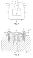
- the stator core 1 of Figure 1 is c-shaped and comprises a back 2, a pair of asymmetric poles 3,4 separated by an air gap 5, and a pair of necks 6,7 extending between the back 2 and the poles 3,4.
- Each pole 3,4 has a first side or face 8 adjacent the air gap 5 and a second side or back 9 remote from the air gap 5.
- Each pole face 8 includes an arcuate recess or pole arc 10 that extends between a leading edge 11 and a trailing edge 12.
- the leading edge 11 of each pole 3,4 is wider than that of the trailing edge 12. Additionally, the leading edge 11 of each pole 3,4 is chamfered.
- the inductance of any winding wound about the stator core 1 is reduced.
- the saturation of the stator core 1 at the leading edges is increased. Consequently, the asymmetry in the poles 3,4 provides a stator of lower inductance without lowering the saturation.
- a pair of mounting recesses 13,14 is formed in the outer perimeter 15 of the stator core 1.
- Each mounting recess 13,14 is semi-circular and is formed in the back 9 of a respective pole 3,4.
- the mounting recesses 13,14 provide means by which the stator core 1 may be secured to a frame, housing or the like of an electric machine, as will now be demonstrated.
- FIGS 2 and 3 illustrate an electric machine 20 incorporating the stator core 1.
- the electric machine 20 comprises a housing 21, a rotor 22, a winding 23, a printed circuit board (PCB) 24, and a pair of non-magnetic screws 25.
- PCB printed circuit board
- the housing 21 is formed of plastic and includes a central bore 26 and a pair of hollow posts 27.
- the stator core 1 is mounted within the housing 21 such that each post 27 is received within a respective mounting recess 13,14 in the stator core 1.
- the winding 23 is wound about the necks 6,7 of the stator core 1. However, the winding 23 might equally be wound about the back 2 of the stator core 1.
- the rotor 22 comprises a shaft 28 to which are mounted a rotor core 29 and a bearing assembly 30.
- the bearing assembly 30 is mounted within the central bore 26 of the housing 21 such that the rotor core 29 is supported between the poles 3,4 of the stator core 1.
- the PCB 24 includes a pair of through-holes 31 and overlies the stator core 1 such that each of the through-holes 31 is aligned with a respective post 27 of the housing 21.
- the winding 23 is electrically coupled to the PCB 24.
- the PCB 24 and the stator core 1 are secured to the housing 21 by the non-magnetic screws 25, which pass through the through-holes 31 in the PCB 24 and screw into the posts 27 of the housing 21.
- the posts 27 of the housing 21 prevent translational and rotational movement of the stator core 1 in the x-y plane. This is particularly important since the interaction of the armature field and rotor field generates forces that act on the stator core 1 within this plane. It is not therefore necessary to screw down tightly the stator core 1 to the housing 21 in order to oppose these forces. Furthermore, in providing mounting recesses 13,14 on opposite sides of the stator core 1, only two recesses 13,14 are required in order to prevent movement of the stator core 1 within the x-y plane.
- the housing 21 of the electric machine 20 is formed of plastic. Consequently, the housing 21 is neither subjected to inductive heating nor does it present a partial short to the magnetic circuit. Additionally, the housing 21 may be manufactured more cheaply in comparison to an equivalent housing formed of a non-magnetic metal.
- a relatively large diameter is required for the posts 27 in order that the posts 27 can oppose the relatively large forces acting on the stator core 1.
- the size of the posts 27 are also limited by the size of the screws 25 used to secure the stator core 1 and PCB 24 to the housing 21. For these reasons, each mounting recess 13,14 is at least 20% of the pole length, i.e. the distance between the face 8 and the back 9 of each pole 3,4.
- each mounting recess 13,14 is only half the size of a through-hole. Consequently, the overall effect on the magnetic flux distribution through the stator core 1 is much smaller than that of a through-hole. Moreover, as will now be explained, the mounting recesses 13,14 are formed at positions that do not decrease the saturation of the stator core 1.
- the stator core 1 has a cross-sectional area normal to lines of magnetic flux through the stator core 1. This cross-sectional area is non-uniform around the stator core 1. In particular, the cross-sectional area increases at the corners of the stator core 1 as the magnetic flux turns through 90 degrees. Additionally, the cross-sectional area of the poles 3,4 is greater than that of the back 2 and the necks 6,7 of the stator core 1; a greater cross-sectional area at the poles 3,4 is necessary in order that the poles 3,4 provide effective capture of the rotor flux.
- the mounting recesses 13,14 are located at positions for which the cross-sectional area of the stator core 1 is greatest. Consequently, the impact of the mounting recesses 13,14 on the magnetic saturation of the stator core 1 is minimal. Indeed, the mounting recesses 13,14 ideally have no effect on the magnetic saturation of the stator core 1, i.e. the mounting recesses 13,14 do not create a bottleneck or other restriction in the cross-sectional area of stator core 1.
- the width of the stator core 1 is the distance between the outer perimeter 15 and the inner perimeter 16 of the stator core 1.
- the width of the stator core 1 has a minimum.
- the poles 3,4 are wider than the back 2 and necks 6,7 of the stator core 1 in order that the poles 3,4 provide effective capture of the rotor flux.
- the stator width therefore has a minimum at some point along the back 2 or neck 6,7 of the stator core 1.
- the shortest distance between the edge of each mounting recess 13,14 and the inner perimeter 16 of the stator core 1 is no less than the minimal width of the stator core 1. Additionally, the shortest distance between the edge of each mounting recess 13,14 and a respective pole arc 10 is no less than half the minimal width of the stator core 1. Consequently, the mounting recesses 13,14 do not form a bottleneck or other restriction in the stator core 1 and do not therefore reduce the saturation of the stator core 1.
- the posts 27 of the housing 21 are relatively large and thus the mounting recesses 13,14 are equally relatively large.
- one of the mounting recesses 14 creates a restriction in the width of the stator core 1. Accordingly, in order to compensate for this restriction, the width of the corresponding neck 7 increases at the end adjacent the pole 3. Consequently, the distance between the edge of the mounting recess 14 and the inner perimeter 16 of the stator core 1 continues to be no less than the minimal width of the stator core 1.
- stator core 1 is held within the housing 21 by posts 27 that form an integral part of the housing 21.
- the stator core 1 might equally be held by alternate means.
- the stator core 1 might be bolted to the housing 21 by a pair of bolts, each bolt extending through and received within a mounting recess 13,14 in the stator core 1.
- stator core 1 of the present invention includes mounting recesses 13,14 that are formed within the normal profile of the stator core 1. Consequently, a more compact and cheaper stator core 1 may be realised.
- stator core laminations can be produced by stamping or cutting sheet material (e.g. steel) with little waste.
Landscapes
- Engineering & Computer Science (AREA)
- Power Engineering (AREA)
- Iron Core Of Rotating Electric Machines (AREA)
- Motor Or Generator Frames (AREA)
Abstract
Description
- The present invention relates to a stator core for an electric machine, and to an electric machine incorporating the same.
- Various methods are available for securing a stator within the housing of an electric machine. One such method involves the provision of through-holes in the stator core. The stator core may then be secured to the housing by bolts that pass through the holes. Typically, however, the through-holes adversely affect the magnetic flux through the stator core and thus the performance of the electric machine is compromised.
- In a first aspect, the present invention provides a stator core comprising a pair of poles separated by an air gap, each pole comprising a first side adjacent the air gap, a second opposite side remote from the air gap, a pole arc formed in the first side, and an mounting recess formed in the second side, wherein the mounting recess is semi-circular and has a depth that is at least 20% of the distance between the first side and the second side.
- The stator core may then be held within an electric machine by posts, bolts or other means received with the mounting recesses. By providing mounting recesses on the sides of the poles, the impact on the magnetic flux distribution through the stator core is much smaller than that of a through-hole. Indeed, the position and size of the mounting recesses is ideally selected such that the recesses do not impact, or impact only marginally, on the saturation of the stator core. Moreover, by providing mounting recesses on the sides of the poles, movement of the poles relative to a rotor of the electric machine is better restricted and thus the performance of the electric machine is improved.
- By having mounting recesses that are semi-circular in shape, the forces acting on the stator core during subsequent use may be more evenly distributed over the means used to hold the stator core. Moreover, since each mounting recess has a radius that is at least 20% of the distance between the first side and the second side, the size of each mounting recess is relatively large. As a result, the means used to hold the stator core may be equally large. The stator core may then be held by plastic posts, which, being made of plastic, are preferably large in order to oppose the forces acting on the stator during subsequent use.
- Preferably, the stator core has a minimal width between the outer perimeter and the inner perimeter of the stator core, and the shortest distance between an edge of each mounting recess and the inner perimeter of the stator core is at least that of the minimal width. Accordingly, neither of the mounting recesses generates a bottleneck or other restriction in the cross-sectional area of the stator core; the magnetic saturation of the stator core is thus unaffected by the mounting recesses.
- The shortest distance between an edge of each mounting recess and a respective pole arc is advantageously at least half the minimal width of the stator core. Again, this then ensures that the mounting recesses do not adversely affect the magnetic saturation of the stator core.
- The stator core may comprise a back and a pair of necks, each neck connecting a respective pole to the back. The shortest distance between an edge of each mounting recess and the inner perimeter of the stator core is then ideally at least equal to a width of one of the back and necks. The width of each pole is generally greater than that of the back and necks in order that the poles provide effective capture of rotor flux. By ensuring that the distance between each mounting recess and the inner perimeter of the stator core is at least the width of the back or necks, the mounting recesses do not adversely affect the magnetic saturation of the stator core.
- The stator core may comprise a back and a pair of necks, each neck connecting a respective pole to the back. The width of at least one neck may then increase at an end adjacent the respective pole. By increasing the width of the neck adjacent the pole, any restriction in cross-sectional area that would otherwise arise because of the mounting recess may be compensated.
- Each pole may comprise a pole arc extending between a leading edge and a trailing edge, with the leading edge being wider than the trailing edge. This asymmetry in the poles then provides a stator of lower inductance without lowering the saturation.
- Advantageously, the stator core is c-shaped. A winding may then be more easily wound on to the stator core via the slot opening between the poles. Additionally, a high fill factor for the winding can be achieved, which then reduces copper losses and thus improves efficiency. Furthermore, owing to the generally square or rectangular shape of the stator core, the stator core may be formed by stamping or cutting sheet material with little waste.
- Reference herein to a c-shaped stator core should also be understood to include u-shaped stator cores.
- Preferably, the stator core is formed of a plurality of single-piece laminations. Owing to the location of the mounting recesses, the laminations may be stamped or cut from sheet material such that mounting recesses of two adjacent laminations define a circular hole, thus simplifying manufacture.
- In a second aspect, the present invention provides an electric machine comprising a housing and a stator core as described in any one of the preceding paragraphs, the housing comprising a pair of posts, and the stator core being mounted within the housing such that each post is received within a respective mounting recess.
- The housing is preferably formed of plastic. This then has the advantage that the housing is neither subjected to inductive heating nor does it present a partial short to the magnetic circuit. Furthermore, the housing is cheaper that an equivalent housing formed of a non-magnetic metal.
- Advantageously, the posts are hollow and can thus receive a screw or the like. The electric machine may then comprise a printed circuit board that overlies the stator core and is screwed to the posts. For example, the printed circuit board may include a pair of through-holes, each of which aligns with a respective post and through which a screw projects into a hollow post. This then has the advantage of providing a compact electric machine.
- The electric machine may additionally include a rotor comprising a shaft to which are mounted a rotor core and a bearing. The bearing is then advantageously mounted within a bore in the housing such that the rotor core is supported between the poles of the stator core. By securing the stator core and the rotor to the same housing, alignment of the rotor core relative to the stator core is made easier.
- In order that the present invention may be more readily understood, an embodiment of the invention will now be described, by way of example, with reference to the accompanying drawings, in which:
-
Figure 1 is a plane view of a stator core in accordance with the present invention; -
Figure 2 is an exploded view of an electric machine in accordance with the present invention; and -
Figure 3 is a sectional view of the electric machine ofFigure 2 . - The
stator core 1 ofFigure 1 is c-shaped and comprises aback 2, a pair of asymmetric poles 3,4 separated by an air gap 5, and a pair ofnecks back 2 and the poles 3,4. - Each pole 3,4 has a first side or
face 8 adjacent the air gap 5 and a second side or back 9 remote from the air gap 5. Eachpole face 8 includes an arcuate recess orpole arc 10 that extends between a leadingedge 11 and atrailing edge 12. The leadingedge 11 of each pole 3,4 is wider than that of thetrailing edge 12. Additionally, the leadingedge 11 of each pole 3,4 is chamfered. By providing narrowertrailing edges 12 and chamfering the corners of the leadingedges 11, the inductance of any winding wound about thestator core 1 is reduced. However, in having wider leadingedges 11, the saturation of thestator core 1 at the leading edges is increased. Consequently, the asymmetry in the poles 3,4 provides a stator of lower inductance without lowering the saturation. - A pair of
mounting recesses 13,14 is formed in theouter perimeter 15 of thestator core 1. Each mounting recess 13,14 is semi-circular and is formed in theback 9 of a respective pole 3,4. - The
mounting recesses 13,14 provide means by which thestator core 1 may be secured to a frame, housing or the like of an electric machine, as will now be demonstrated. -
Figures 2 and3 illustrate anelectric machine 20 incorporating thestator core 1. In addition to thestator core 1, theelectric machine 20 comprises ahousing 21, arotor 22, a winding 23, a printed circuit board (PCB) 24, and a pair ofnon-magnetic screws 25. - The
housing 21 is formed of plastic and includes acentral bore 26 and a pair ofhollow posts 27. - The
stator core 1 is mounted within thehousing 21 such that eachpost 27 is received within arespective mounting recess 13,14 in thestator core 1. The winding 23 is wound about thenecks stator core 1. However, the winding 23 might equally be wound about theback 2 of thestator core 1. - The
rotor 22 comprises ashaft 28 to which are mounted arotor core 29 and a bearingassembly 30. The bearingassembly 30 is mounted within thecentral bore 26 of thehousing 21 such that therotor core 29 is supported between the poles 3,4 of thestator core 1. By securing thestator core 1 and therotor 22 to thesame housing 21, alignment of therotor core 29 relative to thestator core 1 is made easier. - The
PCB 24 includes a pair of through-holes 31 and overlies thestator core 1 such that each of the through-holes 31 is aligned with arespective post 27 of thehousing 21. The winding 23 is electrically coupled to thePCB 24. - The
PCB 24 and thestator core 1 are secured to thehousing 21 by thenon-magnetic screws 25, which pass through the through-holes 31 in thePCB 24 and screw into theposts 27 of thehousing 21. - By providing mounting
recesses 13,14 on opposite sides of thestator core 1, theposts 27 of thehousing 21 prevent translational and rotational movement of thestator core 1 in the x-y plane. This is particularly important since the interaction of the armature field and rotor field generates forces that act on thestator core 1 within this plane. It is not therefore necessary to screw down tightly thestator core 1 to thehousing 21 in order to oppose these forces. Furthermore, in providing mountingrecesses 13,14 on opposite sides of thestator core 1, only tworecesses 13,14 are required in order to prevent movement of thestator core 1 within the x-y plane. - The forces arising from the interaction of the armature and rotor fields act on the poles 3,4 of the
stator core 1. By providing mountingrecess 13,14 at thebacks 9 of the poles 3,4, movement of the poles 3,4 relative to therotor core 29 is better restricted. By contrast, if mounting recesses were located on theback 2 of thestator core 1, the forces acting on the poles 3,4 would cause the poles 3,4 to move, albeit by a small amount, owing to the flexibility in thenecks rotor core 29 would impact on the performance of theelectric machine 20. By providing mountingrecesses 13,14 on thebacks 9 of the poles 3,4, the positions of the poles 3,4 is better controlled and thus theelectric machine 20 has improved performance. - The
housing 21 of theelectric machine 20 is formed of plastic. Consequently, thehousing 21 is neither subjected to inductive heating nor does it present a partial short to the magnetic circuit. Additionally, thehousing 21 may be manufactured more cheaply in comparison to an equivalent housing formed of a non-magnetic metal. However, in being formed of plastic, a relatively large diameter is required for theposts 27 in order that theposts 27 can oppose the relatively large forces acting on thestator core 1. The size of theposts 27 are also limited by the size of thescrews 25 used to secure thestator core 1 andPCB 24 to thehousing 21. For these reasons, each mountingrecess 13,14 is at least 20% of the pole length, i.e. the distance between theface 8 and theback 9 of each pole 3,4. - By providing mounting
recesses 13,14 in theouter perimeter 15 of thestator core 1, the impact on the magnetic flux distribution through thestator core 1 is smaller than that of an equivalent through-hole. Moreover, each mountingrecess 13,14 is only half the size of a through-hole. Consequently, the overall effect on the magnetic flux distribution through thestator core 1 is much smaller than that of a through-hole. Moreover, as will now be explained, the mountingrecesses 13,14 are formed at positions that do not decrease the saturation of thestator core 1. - Returning to
Figure 1 , thestator core 1 has a cross-sectional area normal to lines of magnetic flux through thestator core 1. This cross-sectional area is non-uniform around thestator core 1. In particular, the cross-sectional area increases at the corners of thestator core 1 as the magnetic flux turns through 90 degrees. Additionally, the cross-sectional area of the poles 3,4 is greater than that of theback 2 and thenecks stator core 1; a greater cross-sectional area at the poles 3,4 is necessary in order that the poles 3,4 provide effective capture of the rotor flux. By providing mountingrecesses 13,14 on thebacks 9 of the poles 3,4, the mountingrecesses 13,14 are located at positions for which the cross-sectional area of thestator core 1 is greatest. Consequently, the impact of the mounting recesses 13,14 on the magnetic saturation of thestator core 1 is minimal. Indeed, the mountingrecesses 13,14 ideally have no effect on the magnetic saturation of thestator core 1, i.e. the mountingrecesses 13,14 do not create a bottleneck or other restriction in the cross-sectional area ofstator core 1. - Since the
stator core 1 is of uniform depth or thickness, the saturation of thestator core 1 may be discussed with reference to the width of thestator core 1. For the purposes of this discussion, the width of thestator core 1 is the distance between theouter perimeter 15 and theinner perimeter 16 of thestator core 1. The width of thestator core 1 has a minimum. As already noted, the poles 3,4 are wider than theback 2 andnecks stator core 1 in order that the poles 3,4 provide effective capture of the rotor flux. The stator width therefore has a minimum at some point along theback 2 orneck stator core 1. Ideally, the shortest distance between the edge of each mountingrecess 13,14 and theinner perimeter 16 of thestator core 1 is no less than the minimal width of thestator core 1. Additionally, the shortest distance between the edge of each mountingrecess 13,14 and arespective pole arc 10 is no less than half the minimal width of thestator core 1. Consequently, the mountingrecesses 13,14 do not form a bottleneck or other restriction in thestator core 1 and do not therefore reduce the saturation of thestator core 1. - As noted above, the
posts 27 of thehousing 21 are relatively large and thus the mounting recesses 13,14 are equally relatively large. For the particular size of mountingrecess 13,14 illustrated inFigure 1 , as well as in the asymmetry in the poles 3,4, one of the mounting recesses 14 creates a restriction in the width of thestator core 1. Accordingly, in order to compensate for this restriction, the width of thecorresponding neck 7 increases at the end adjacent the pole 3. Consequently, the distance between the edge of the mounting recess 14 and theinner perimeter 16 of thestator core 1 continues to be no less than the minimal width of thestator core 1. - In the embodiment described above, the
stator core 1 is held within thehousing 21 byposts 27 that form an integral part of thehousing 21. However, thestator core 1 might equally be held by alternate means. For example, thestator core 1 might be bolted to thehousing 21 by a pair of bolts, each bolt extending through and received within a mountingrecess 13,14 in thestator core 1. - If conventional through-holes were formed in the stator core, the through-holes would reduce the saturation of the stator core. This reduction in saturation might be addressed by making the stator core wider at the points where the through-holes are located. However, not only would this increase the overall size of the stator core, but it would also increase the cost of the stator core owing to the required additional material. In contrast, the
stator core 1 of the present invention includes mountingrecesses 13,14 that are formed within the normal profile of thestator core 1. Consequently, a more compact andcheaper stator core 1 may be realised. Moreover, owing to the generally square profile of thestator core 1, the stator core laminations can be produced by stamping or cutting sheet material (e.g. steel) with little waste.
Claims (14)
- A stator core comprising a pair of poles separated by an air gap, each pole comprising a first side adjacent the air gap, a second opposite side remote from the air gap, a pole arc formed in the first side, and an mounting recess formed in the second side, wherein the mounting recess is semi-circular and has a depth that is at least 20% of the distance between the first side and the second side.
- A stator core as claimed in claim 1, wherein the stator core has a minimal width between an outer perimeter and an inner perimeter of the stator core, and the shortest distance between an edge of each mounting recess and the inner perimeter of the stator core is at least that of the minimal width.
- A stator core as claimed in claim 2, wherein the shortest distance between an edge of each mounting recess and a respective pole arc is at least half the minimal width.
- A stator core as claimed in any one of the preceding claims, wherein the stator core comprises a back and the shortest distance between an edge of each mounting recess and an inner perimeter of the stator core is at least equal to the width of the back.
- A stator core as claimed in any one of the preceding claims, wherein the stator core comprises a back and a pair of necks, each neck connecting a respective pole to the back, and wherein the shortest distance between an edge of each mounting recess and an inner perimeter of the stator core is at least equal to a width of one of the back and the necks.
- A stator core as claimed in any one of the preceding claims, wherein the stator core comprises a back and a pair of necks, each neck connecting a respective pole to the back, and the width of at least one neck increases at an end adjacent the respective pole.
- A stator core as claimed in any one of the preceding claims, wherein each pole comprises a pole arc extending between a leading edge and a trailing edge, and the leading edge is wider than the trailing edge.
- A stator core as claimed in any one of the preceding claims, wherein the stator core is c-shaped.
- A stator core as claimed in any one of the preceding claims, wherein stator core is formed of a plurality of single-piece laminations.
- An electric machine comprising a housing and a stator core as claimed in any one of the preceding claims, the housing comprising a pair of posts, and the stator core being mounted within the housing such that each post is received within a respective mounting recess.
- An electric machine as claimed in claim 10, wherein the housing is formed of plastic.
- An electric machine as claimed in claim 10 or 11, wherein the posts are hollow.
- An electric machine as claimed in claim 12, wherein the electric machine comprises a printed circuit board that overlies the stator core and is screwed to the posts.
- An electric machine as claimed in any one of claims 10 to 13, wherein the electric machine comprises a rotor, the rotor comprising a shaft to which are mounted a rotor core and a bearing assembly, and the bearing assembly is mounted within a bore in the housing such that the rotor core is supported between the poles of the stator core.
Applications Claiming Priority (1)
| Application Number | Priority Date | Filing Date | Title |
|---|---|---|---|
| GB0903662.5A GB2468310B (en) | 2009-03-03 | 2009-03-03 | Stator core |
Publications (3)
| Publication Number | Publication Date |
|---|---|
| EP2226916A2 true EP2226916A2 (en) | 2010-09-08 |
| EP2226916A3 EP2226916A3 (en) | 2014-12-10 |
| EP2226916B1 EP2226916B1 (en) | 2017-05-03 |
Family
ID=40580560
Family Applications (1)
| Application Number | Title | Priority Date | Filing Date |
|---|---|---|---|
| EP10154289.2A Active EP2226916B1 (en) | 2009-03-03 | 2010-02-22 | Stator core |
Country Status (4)
| Country | Link |
|---|---|
| US (1) | US9564778B2 (en) |
| EP (1) | EP2226916B1 (en) |
| JP (1) | JP5137986B2 (en) |
| GB (1) | GB2468310B (en) |
Cited By (1)
| Publication number | Priority date | Publication date | Assignee | Title |
|---|---|---|---|---|
| EP2824519A1 (en) * | 2013-07-11 | 2015-01-14 | ETA SA Manufacture Horlogère Suisse | Single-phase timepiece motor |
Families Citing this family (9)
| Publication number | Priority date | Publication date | Assignee | Title |
|---|---|---|---|---|
| US10056813B2 (en) * | 2013-09-18 | 2018-08-21 | E.V.R. Motors Ltd. | Multipole electrical machine |
| EP2922071B1 (en) * | 2014-03-19 | 2019-12-18 | Goodrich Actuation Systems SAS | Servo valve torque motor |
| CN104283335B (en) * | 2014-05-28 | 2017-08-18 | 莱克电气股份有限公司 | A kind of stator structure and its forming method of brushless motor of dust collector |
| GB2545413B (en) | 2015-12-11 | 2019-04-03 | Dyson Technology Ltd | A stator assembly |
| GB2545268B (en) | 2015-12-11 | 2019-04-03 | Dyson Technology Ltd | An electric motor |
| EP3513624B1 (en) * | 2016-09-13 | 2023-10-18 | Ralph Meichtry | Device for removing dents |
| US20250213029A1 (en) | 2023-01-19 | 2025-07-03 | Sharkninja Operating Llc | Hair care appliance with powered attachment |
| US12696964B2 (en) | 2023-01-19 | 2026-08-04 | Sharkninja Operating Llc | Identification of hair care appliance attachments |
| US12614963B2 (en) * | 2023-06-16 | 2026-04-28 | Regal Beloit America, Inc. | Non-axisymmetric motor with integrated magnetic gearing |
Family Cites Families (36)
| Publication number | Priority date | Publication date | Assignee | Title |
|---|---|---|---|---|
| US2298388A (en) * | 1941-02-10 | 1942-10-13 | Houdaille Hershey Corp | Laminated field structure |
| US2460921A (en) * | 1946-08-17 | 1949-02-08 | Nat Cylinder Gas Co | Magnetic control system |
| US2606083A (en) * | 1947-10-17 | 1952-08-05 | G M Lab Inc | Spring thrust washer |
| FR1078092A (en) * | 1952-06-05 | 1954-11-15 | Thomson Houston Comp Francaise | Dynamoelectric machine |
| JPS4933111A (en) * | 1972-07-31 | 1974-03-27 | ||
| JPS5814144B2 (en) * | 1975-09-23 | 1983-03-17 | 株式会社精工舎 | Kogata motor |
| JPS5826262B2 (en) * | 1976-04-12 | 1983-06-01 | 三洋電機株式会社 | capacitor motor |
| US4162418A (en) * | 1976-12-14 | 1979-07-24 | Niles Parts Co., Ltd. | Stepping motor for electronic clock |
| US4224544A (en) * | 1978-10-05 | 1980-09-23 | Mckinnon Eugene T | Fan motor having reversible rotor |
| FR2450527A1 (en) * | 1979-03-01 | 1980-09-26 | Suisse Horlogerie | NON REVERSIBLE STEPPER MOTOR |
| DE2911439C2 (en) * | 1979-03-23 | 1982-12-09 | Gebrüder Junghans GmbH, 7230 Schramberg | Electromagnetic converter for driving an electric clock |
| JPS5694173U (en) * | 1979-12-19 | 1981-07-27 | ||
| JPS6145503Y2 (en) * | 1980-07-24 | 1986-12-20 | ||
| JPS5728391A (en) | 1980-07-29 | 1982-02-16 | Fujitsu Ltd | Optical semiconductor device |
| DE3225435A1 (en) * | 1982-07-07 | 1984-01-12 | Hermann Mellert GmbH & Co KG Fabrik für Feinmechanik und Elektrotechnik, 7518 Bretten | SELF-STARTING ELECTRIC MOTOR |
| US4528533A (en) * | 1982-07-28 | 1985-07-09 | General Scanning, Inc. | Actuator with compensating flux path |
| JPS5980147A (en) * | 1982-10-29 | 1984-05-09 | Rhythm Watch Co Ltd | Small motor for timepiece |
| JPS6274461U (en) * | 1985-10-30 | 1987-05-13 | ||
| JPS63681U (en) * | 1986-06-19 | 1988-01-06 | ||
| JPS63681A (en) | 1986-06-19 | 1988-01-05 | Fujitsu Ltd | Uneven surface information detector |
| JPS6315164U (en) * | 1986-07-14 | 1988-02-01 | ||
| JP2604143B2 (en) * | 1987-01-14 | 1997-04-30 | 三洋電機株式会社 | Small brushless motor |
| US5128576A (en) * | 1987-01-28 | 1992-07-07 | Emerson Electric Co. | Rotor assembly and motor construction and method of making same |
| JPS63153771U (en) * | 1987-03-24 | 1988-10-07 | ||
| US6348752B1 (en) * | 1992-04-06 | 2002-02-19 | General Electric Company | Integral motor and control |
| US5675226A (en) * | 1995-09-06 | 1997-10-07 | C.E.Set. S.R.L. | Control circuit for an synchronous electric motor of the brushless type |
| JPH1023690A (en) * | 1996-06-28 | 1998-01-23 | Sankyo Seiki Mfg Co Ltd | Electric motor |
| JP2000092755A (en) * | 1998-09-07 | 2000-03-31 | Mitsubishi Electric Corp | Rotating electric machine or linear motor and method of manufacturing rotating electric machine |
| KR100429989B1 (en) | 2001-05-26 | 2004-05-03 | 엘지전자 주식회사 | Skeleton type brushless direct current motor |
| US6975049B2 (en) * | 2003-10-29 | 2005-12-13 | A. O. Smith Corporation | Electrical machine and method of manufacturing the same |
| US6982532B2 (en) * | 2003-12-08 | 2006-01-03 | A. O. Smith Corporation | Electric machine |
| ITTO20040366A1 (en) * | 2004-05-31 | 2004-08-31 | C E Set Srl | CIRCUIT FOR PILOTING A SYNCHRONOUS ELECTRIC MOTOR |
| US7109621B2 (en) | 2004-08-20 | 2006-09-19 | A. O. Smith Corporation | Electric motor having a printed circuit board attached to a stator and at least partially supporting a bearing |
| DE602005026626D1 (en) | 2005-04-12 | 2011-04-14 | Lg Electronics Inc | Brushless shaded pole motor |
| CN1980001A (en) * | 2005-12-05 | 2007-06-13 | 德昌电机股份有限公司 | General motor and its stator lamination |
| JP4483895B2 (en) * | 2007-05-01 | 2010-06-16 | ダイキン工業株式会社 | Rotating electric machine and compressor |
-
2009
- 2009-03-03 GB GB0903662.5A patent/GB2468310B/en active Active
-
2010
- 2010-02-19 US US12/709,293 patent/US9564778B2/en active Active
- 2010-02-22 EP EP10154289.2A patent/EP2226916B1/en active Active
- 2010-03-03 JP JP2010046152A patent/JP5137986B2/en not_active Expired - Fee Related
Non-Patent Citations (1)
| Title |
|---|
| None |
Cited By (1)
| Publication number | Priority date | Publication date | Assignee | Title |
|---|---|---|---|---|
| EP2824519A1 (en) * | 2013-07-11 | 2015-01-14 | ETA SA Manufacture Horlogère Suisse | Single-phase timepiece motor |
Also Published As
| Publication number | Publication date |
|---|---|
| US9564778B2 (en) | 2017-02-07 |
| US20100225197A1 (en) | 2010-09-09 |
| GB2468310B (en) | 2015-01-07 |
| JP2010207081A (en) | 2010-09-16 |
| GB2468310A (en) | 2010-09-08 |
| JP5137986B2 (en) | 2013-02-06 |
| EP2226916A3 (en) | 2014-12-10 |
| EP2226916B1 (en) | 2017-05-03 |
| GB0903662D0 (en) | 2009-04-15 |
Similar Documents
| Publication | Publication Date | Title |
|---|---|---|
| EP2226916B1 (en) | Stator core | |
| JP4755117B2 (en) | Rotor, blower and compressor of embedded permanent magnet motor | |
| KR101255934B1 (en) | Transverse type switched reluctance motor | |
| FI121614B (en) | Permanent magnet module for an electric machine | |
| US10224797B2 (en) | Linear motor | |
| US20080303369A1 (en) | Electric motor, stator for an electric motor and method of manufacturing same | |
| US20140084734A1 (en) | Rotating Electrical Machine, Method for Manufacturing Magnetic Pole Piece | |
| US7471018B2 (en) | Linear motor and manufacturing method of linear motor | |
| JP2010220324A (en) | Electric motor, compressor, and air conditioner | |
| JP4709132B2 (en) | Rotor of permanent magnet embedded motor, motor for blower and motor for compressor | |
| GB2565473A (en) | Consequent-pole rotor, electric motor, and air conditioner | |
| JP4717089B2 (en) | Electric motor stator, electric motor, compressor and blower | |
| US8461736B2 (en) | Electric motor for operating a shutter element or solar protection element in a building | |
| JP5242720B2 (en) | Rotor of permanent magnet embedded motor | |
| AT509029B1 (en) | PERMANENT MAGNETIC RACK MACHINE | |
| GB2512772A (en) | Electric machine | |
| US6919660B2 (en) | Linear brushless DC motor with ironcore composite armature assembly | |
| CN112072816B (en) | Rotor structure and motor with same | |
| JP2004328887A (en) | Stepping motor | |
| JP2007300796A (en) | Rotor for permanent magnet type motor | |
| JP7005741B2 (en) | Permanent magnet type motor | |
| CN110291699A (en) | motor | |
| US11404925B2 (en) | Permanent magnet motor | |
| JP2006109700A (en) | Interior permanent magnet motor | |
| JP2001086718A (en) | Self-starting permanent magnet synchronous motor and method of manufacturing the same |
Legal Events
| Date | Code | Title | Description |
|---|---|---|---|
| PUAI | Public reference made under article 153(3) epc to a published international application that has entered the european phase |
Free format text: ORIGINAL CODE: 0009012 |
|
| AK | Designated contracting states |
Kind code of ref document: A2 Designated state(s): AT BE BG CH CY CZ DE DK EE ES FI FR GB GR HR HU IE IS IT LI LT LU LV MC MK MT NL NO PL PT RO SE SI SK SM TR |
|
| PUAL | Search report despatched |
Free format text: ORIGINAL CODE: 0009013 |
|
| AK | Designated contracting states |
Kind code of ref document: A3 Designated state(s): AT BE BG CH CY CZ DE DK EE ES FI FR GB GR HR HU IE IS IT LI LT LU LV MC MK MT NL NO PL PT RO SE SI SK SM TR |
|
| RIC1 | Information provided on ipc code assigned before grant |
Ipc: H02K 1/14 20060101AFI20141105BHEP Ipc: H02K 21/18 20060101ALI20141105BHEP Ipc: H02K 1/18 20060101ALI20141105BHEP |
|
| 17P | Request for examination filed |
Effective date: 20150605 |
|
| RBV | Designated contracting states (corrected) |
Designated state(s): AT BE BG CH CY CZ DE DK EE ES FI FR GB GR HR HU IE IS IT LI LT LU LV MC MK MT NL NO PL PT RO SE SI SK SM TR |
|
| 17Q | First examination report despatched |
Effective date: 20160104 |
|
| GRAP | Despatch of communication of intention to grant a patent |
Free format text: ORIGINAL CODE: EPIDOSNIGR1 |
|
| INTG | Intention to grant announced |
Effective date: 20161221 |
|
| GRAS | Grant fee paid |
Free format text: ORIGINAL CODE: EPIDOSNIGR3 |
|
| GRAA | (expected) grant |
Free format text: ORIGINAL CODE: 0009210 |
|
| AK | Designated contracting states |
Kind code of ref document: B1 Designated state(s): AT BE BG CH CY CZ DE DK EE ES FI FR GB GR HR HU IE IS IT LI LT LU LV MC MK MT NL NO PL PT RO SE SI SK SM TR |
|
| REG | Reference to a national code |
Ref country code: GB Ref legal event code: FG4D |
|
| REG | Reference to a national code |
Ref country code: AT Ref legal event code: REF Ref document number: 890988 Country of ref document: AT Kind code of ref document: T Effective date: 20170515 Ref country code: CH Ref legal event code: EP |
|
| REG | Reference to a national code |
Ref country code: IE Ref legal event code: FG4D |
|
| REG | Reference to a national code |
Ref country code: DE Ref legal event code: R096 Ref document number: 602010041959 Country of ref document: DE |
|
| REG | Reference to a national code |
Ref country code: NL Ref legal event code: MP Effective date: 20170503 |
|
| REG | Reference to a national code |
Ref country code: AT Ref legal event code: MK05 Ref document number: 890988 Country of ref document: AT Kind code of ref document: T Effective date: 20170503 |
|
| REG | Reference to a national code |
Ref country code: LT Ref legal event code: MG4D |
|
| PG25 | Lapsed in a contracting state [announced via postgrant information from national office to epo] |
Ref country code: AT Free format text: LAPSE BECAUSE OF FAILURE TO SUBMIT A TRANSLATION OF THE DESCRIPTION OR TO PAY THE FEE WITHIN THE PRESCRIBED TIME-LIMIT Effective date: 20170503 Ref country code: LT Free format text: LAPSE BECAUSE OF FAILURE TO SUBMIT A TRANSLATION OF THE DESCRIPTION OR TO PAY THE FEE WITHIN THE PRESCRIBED TIME-LIMIT Effective date: 20170503 Ref country code: FI Free format text: LAPSE BECAUSE OF FAILURE TO SUBMIT A TRANSLATION OF THE DESCRIPTION OR TO PAY THE FEE WITHIN THE PRESCRIBED TIME-LIMIT Effective date: 20170503 Ref country code: HR Free format text: LAPSE BECAUSE OF FAILURE TO SUBMIT A TRANSLATION OF THE DESCRIPTION OR TO PAY THE FEE WITHIN THE PRESCRIBED TIME-LIMIT Effective date: 20170503 Ref country code: NO Free format text: LAPSE BECAUSE OF FAILURE TO SUBMIT A TRANSLATION OF THE DESCRIPTION OR TO PAY THE FEE WITHIN THE PRESCRIBED TIME-LIMIT Effective date: 20170803 Ref country code: ES Free format text: LAPSE BECAUSE OF FAILURE TO SUBMIT A TRANSLATION OF THE DESCRIPTION OR TO PAY THE FEE WITHIN THE PRESCRIBED TIME-LIMIT Effective date: 20170503 Ref country code: GR Free format text: LAPSE BECAUSE OF FAILURE TO SUBMIT A TRANSLATION OF THE DESCRIPTION OR TO PAY THE FEE WITHIN THE PRESCRIBED TIME-LIMIT Effective date: 20170804 |
|
| PG25 | Lapsed in a contracting state [announced via postgrant information from national office to epo] |
Ref country code: IS Free format text: LAPSE BECAUSE OF FAILURE TO SUBMIT A TRANSLATION OF THE DESCRIPTION OR TO PAY THE FEE WITHIN THE PRESCRIBED TIME-LIMIT Effective date: 20170903 Ref country code: NL Free format text: LAPSE BECAUSE OF FAILURE TO SUBMIT A TRANSLATION OF THE DESCRIPTION OR TO PAY THE FEE WITHIN THE PRESCRIBED TIME-LIMIT Effective date: 20170503 Ref country code: PL Free format text: LAPSE BECAUSE OF FAILURE TO SUBMIT A TRANSLATION OF THE DESCRIPTION OR TO PAY THE FEE WITHIN THE PRESCRIBED TIME-LIMIT Effective date: 20170503 Ref country code: LV Free format text: LAPSE BECAUSE OF FAILURE TO SUBMIT A TRANSLATION OF THE DESCRIPTION OR TO PAY THE FEE WITHIN THE PRESCRIBED TIME-LIMIT Effective date: 20170503 Ref country code: SE Free format text: LAPSE BECAUSE OF FAILURE TO SUBMIT A TRANSLATION OF THE DESCRIPTION OR TO PAY THE FEE WITHIN THE PRESCRIBED TIME-LIMIT Effective date: 20170503 Ref country code: BG Free format text: LAPSE BECAUSE OF FAILURE TO SUBMIT A TRANSLATION OF THE DESCRIPTION OR TO PAY THE FEE WITHIN THE PRESCRIBED TIME-LIMIT Effective date: 20170803 |
|
| PG25 | Lapsed in a contracting state [announced via postgrant information from national office to epo] |
Ref country code: DK Free format text: LAPSE BECAUSE OF FAILURE TO SUBMIT A TRANSLATION OF THE DESCRIPTION OR TO PAY THE FEE WITHIN THE PRESCRIBED TIME-LIMIT Effective date: 20170503 Ref country code: SK Free format text: LAPSE BECAUSE OF FAILURE TO SUBMIT A TRANSLATION OF THE DESCRIPTION OR TO PAY THE FEE WITHIN THE PRESCRIBED TIME-LIMIT Effective date: 20170503 Ref country code: EE Free format text: LAPSE BECAUSE OF FAILURE TO SUBMIT A TRANSLATION OF THE DESCRIPTION OR TO PAY THE FEE WITHIN THE PRESCRIBED TIME-LIMIT Effective date: 20170503 Ref country code: RO Free format text: LAPSE BECAUSE OF FAILURE TO SUBMIT A TRANSLATION OF THE DESCRIPTION OR TO PAY THE FEE WITHIN THE PRESCRIBED TIME-LIMIT Effective date: 20170503 Ref country code: CZ Free format text: LAPSE BECAUSE OF FAILURE TO SUBMIT A TRANSLATION OF THE DESCRIPTION OR TO PAY THE FEE WITHIN THE PRESCRIBED TIME-LIMIT Effective date: 20170503 |
|
| REG | Reference to a national code |
Ref country code: DE Ref legal event code: R097 Ref document number: 602010041959 Country of ref document: DE |
|
| PG25 | Lapsed in a contracting state [announced via postgrant information from national office to epo] |
Ref country code: SM Free format text: LAPSE BECAUSE OF FAILURE TO SUBMIT A TRANSLATION OF THE DESCRIPTION OR TO PAY THE FEE WITHIN THE PRESCRIBED TIME-LIMIT Effective date: 20170503 Ref country code: IT Free format text: LAPSE BECAUSE OF FAILURE TO SUBMIT A TRANSLATION OF THE DESCRIPTION OR TO PAY THE FEE WITHIN THE PRESCRIBED TIME-LIMIT Effective date: 20170503 |
|
| PLBE | No opposition filed within time limit |
Free format text: ORIGINAL CODE: 0009261 |
|
| STAA | Information on the status of an ep patent application or granted ep patent |
Free format text: STATUS: NO OPPOSITION FILED WITHIN TIME LIMIT |
|
| 26N | No opposition filed |
Effective date: 20180206 |
|
| PG25 | Lapsed in a contracting state [announced via postgrant information from national office to epo] |
Ref country code: SI Free format text: LAPSE BECAUSE OF FAILURE TO SUBMIT A TRANSLATION OF THE DESCRIPTION OR TO PAY THE FEE WITHIN THE PRESCRIBED TIME-LIMIT Effective date: 20170503 |
|
| REG | Reference to a national code |
Ref country code: CH Ref legal event code: PL |
|
| PG25 | Lapsed in a contracting state [announced via postgrant information from national office to epo] |
Ref country code: MC Free format text: LAPSE BECAUSE OF FAILURE TO SUBMIT A TRANSLATION OF THE DESCRIPTION OR TO PAY THE FEE WITHIN THE PRESCRIBED TIME-LIMIT Effective date: 20170503 |
|
| REG | Reference to a national code |
Ref country code: IE Ref legal event code: MM4A |
|
| REG | Reference to a national code |
Ref country code: BE Ref legal event code: MM Effective date: 20180228 |
|
| PG25 | Lapsed in a contracting state [announced via postgrant information from national office to epo] |
Ref country code: LI Free format text: LAPSE BECAUSE OF NON-PAYMENT OF DUE FEES Effective date: 20180228 Ref country code: CH Free format text: LAPSE BECAUSE OF NON-PAYMENT OF DUE FEES Effective date: 20180228 Ref country code: LU Free format text: LAPSE BECAUSE OF NON-PAYMENT OF DUE FEES Effective date: 20180222 |
|
| REG | Reference to a national code |
Ref country code: FR Ref legal event code: ST Effective date: 20181031 |
|
| PG25 | Lapsed in a contracting state [announced via postgrant information from national office to epo] |
Ref country code: IE Free format text: LAPSE BECAUSE OF NON-PAYMENT OF DUE FEES Effective date: 20180222 |
|
| PG25 | Lapsed in a contracting state [announced via postgrant information from national office to epo] |
Ref country code: BE Free format text: LAPSE BECAUSE OF NON-PAYMENT OF DUE FEES Effective date: 20180228 Ref country code: FR Free format text: LAPSE BECAUSE OF NON-PAYMENT OF DUE FEES Effective date: 20180228 |
|
| PG25 | Lapsed in a contracting state [announced via postgrant information from national office to epo] |
Ref country code: MT Free format text: LAPSE BECAUSE OF NON-PAYMENT OF DUE FEES Effective date: 20180222 |
|
| PG25 | Lapsed in a contracting state [announced via postgrant information from national office to epo] |
Ref country code: TR Free format text: LAPSE BECAUSE OF FAILURE TO SUBMIT A TRANSLATION OF THE DESCRIPTION OR TO PAY THE FEE WITHIN THE PRESCRIBED TIME-LIMIT Effective date: 20170503 |
|
| PGFP | Annual fee paid to national office [announced via postgrant information from national office to epo] |
Ref country code: DE Payment date: 20200121 Year of fee payment: 11 |
|
| PG25 | Lapsed in a contracting state [announced via postgrant information from national office to epo] |
Ref country code: PT Free format text: LAPSE BECAUSE OF FAILURE TO SUBMIT A TRANSLATION OF THE DESCRIPTION OR TO PAY THE FEE WITHIN THE PRESCRIBED TIME-LIMIT Effective date: 20170503 Ref country code: HU Free format text: LAPSE BECAUSE OF FAILURE TO SUBMIT A TRANSLATION OF THE DESCRIPTION OR TO PAY THE FEE WITHIN THE PRESCRIBED TIME-LIMIT; INVALID AB INITIO Effective date: 20100222 |
|
| PG25 | Lapsed in a contracting state [announced via postgrant information from national office to epo] |
Ref country code: CY Free format text: LAPSE BECAUSE OF FAILURE TO SUBMIT A TRANSLATION OF THE DESCRIPTION OR TO PAY THE FEE WITHIN THE PRESCRIBED TIME-LIMIT Effective date: 20170503 Ref country code: MK Free format text: LAPSE BECAUSE OF NON-PAYMENT OF DUE FEES Effective date: 20170503 |
|
| REG | Reference to a national code |
Ref country code: DE Ref legal event code: R119 Ref document number: 602010041959 Country of ref document: DE |
|
| PG25 | Lapsed in a contracting state [announced via postgrant information from national office to epo] |
Ref country code: DE Free format text: LAPSE BECAUSE OF NON-PAYMENT OF DUE FEES Effective date: 20210901 |
|
| P01 | Opt-out of the competence of the unified patent court (upc) registered |
Effective date: 20230421 |
|
| PGFP | Annual fee paid to national office [announced via postgrant information from national office to epo] |
Ref country code: GB Payment date: 20241205 Year of fee payment: 16 |