EP2226766A2 - Surveillance de la santé de système de rotor utilisant de mesures de charge à arbres et surveillance virtuelle des charges - Google Patents
Surveillance de la santé de système de rotor utilisant de mesures de charge à arbres et surveillance virtuelle des charges Download PDFInfo
- Publication number
- EP2226766A2 EP2226766A2 EP10154881A EP10154881A EP2226766A2 EP 2226766 A2 EP2226766 A2 EP 2226766A2 EP 10154881 A EP10154881 A EP 10154881A EP 10154881 A EP10154881 A EP 10154881A EP 2226766 A2 EP2226766 A2 EP 2226766A2
- Authority
- EP
- European Patent Office
- Prior art keywords
- main rotor
- recited
- load
- aircraft
- rotor shaft
- Prior art date
- Legal status (The legal status is an assumption and is not a legal conclusion. Google has not performed a legal analysis and makes no representation as to the accuracy of the status listed.)
- Ceased
Links
Images


Classifications
-
- G—PHYSICS
- G07—CHECKING-DEVICES
- G07C—TIME OR ATTENDANCE REGISTERS; REGISTERING OR INDICATING THE WORKING OF MACHINES; GENERATING RANDOM NUMBERS; VOTING OR LOTTERY APPARATUS; ARRANGEMENTS, SYSTEMS OR APPARATUS FOR CHECKING NOT PROVIDED FOR ELSEWHERE
- G07C5/00—Registering or indicating the working of vehicles
- G07C5/08—Registering or indicating performance data other than driving, working, idle, or waiting time, with or without registering driving, working, idle or waiting time
- G07C5/0816—Indicating performance data, e.g. occurrence of a malfunction
Definitions
- the present disclosure relates to a health monitoring system, and more particularly to a real-time fault detection and isolation system.
- Helicopter rotor systems may be subject to a number of fault types such as imbalance, track splits, cracks, defects, and freeplay or friction in the pitch control systems, lag systems and flap systems. Early detection and diagnoses of these fault conditions facilitates the reduction of aircraft maintenance costs and further enhances flight safety.
- a method of real-time rotor fault detection includes measuring a set of loads to obtain measured signals and virtually monitoring the set of loads to obtain estimated signals.
- the estimated signals are subtracted from the measured signals to obtain residuals and the residuals are compared to a categorical model.
- a categorical output representative of a rotor fault is identified within the categorical model.
- a method to virtually monitor a load on a rotor system of a rotary wing aircraft includes sampling at least one aircraft parameter once per main rotor revolution. Calculating coefficients for a set of high-frequency waveforms from the at least one aircraft parameter. Multiplying each of the set of high-frequency waveforms by the coefficient to obtain a set of weighted waveforms. Summing the weighted waveforms to produce an estimate of the load on the rotor system.
- FIG. 1 schematically illustrates an exemplary vertical takeoff and landing (VTOL) rotary-wing aircraft 10.
- the aircraft 10 in the disclosed, non-limiting embodiment includes a main rotor system 12 supported by an airframe 14 having an extending tail 16 which mounts an anti-torque system 18.
- the main rotor system 12 is driven about an axis of rotation A through a main rotor gearbox (MGB) 20 by a multi-engine powerplant system 22 - here having two engine packages ENG1, ENG2.
- the multi-engine powerplant system 22 generates the power available for flight operations and couples such power to the main rotor assembly 12 and the anti-torque system 18 through the MGB 20.
- MGB main rotor gearbox
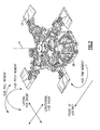
- the main rotor system 12 includes a multiple of rotor blades 24 mounted to a rotor hub 26 driven by a main rotor shaft 28 ( Figure 2 ). Although a particular helicopter configuration is illustrated and described in the disclosed embodiment, other configurations and/or machines, which have a rotating frame of reference and a fixed frame of reference will also benefit herefrom.
- the main rotor system 12 may be subject to various faults which are known to manifest themselves in changes in the amplitude or phase of the main rotor hub moments and in-plane shears typically at the 0th, 1st, 2nd, and Bth harmonics.
- the 0th, 1st, 2nd, and 4th harmonics may be uniquely suited to a rotary-wing aircraft main rotor system 12 with four blades 24.
- the harmonics may be defined as: 0th harmonic (steady load); 1st harmonic (once per revolution); 2nd harmonic (specific blade gets to the opposite position on the rotor disk; and the Bth harmonic in which B equals 4 for a 4 blade rotary-wing aircraft; B equals 6 for a 6 blade rotary-wing aircraft; B equals 7 for a 7 bladed rotary-wing aircraft, etc.
- the main rotor system 12 is instrumented to measure loads to obtain measured signals in combination with the virtual monitoring of the same loads to obtain estimated signals of the loads.
- a residual is calculated by subtraction of the estimated signals from the measured signals.
- This residual is highly sensitive to rotor system damage, even in the presence of disturbances which result from aircraft operating condition. For example, by monitoring magnitude and phase residuals at the 0th, 1st, 2nd, and 4th harmonics, rotor system damage can be readily detected and diagnosed.
- Analytical models are used to predict how rotor system faults may be manifest in amplitude and phase of rotor hub moments and shears but are of significant complexity.
- Empirical models are not as accurate as analytical models but provide estimates in real-time what the loads should be for a healthy aircraft given the operational condition of the aircraft.
- Feature extraction models are then developed from the empirical models to provide fault detection and isolation finding, based on calculated residuals.
- the analytical load models may be developed with modeling software such as Rotorcraft Comprehensive Analysis System (RCAS); Automated Dynamic Analysis of Mechanical Systems (ADAMS), University of Maryland Advanced Rotorcraft Code (UMARC) or others may be used to build an aeroelastic model of the rotor system including for example only, the rotor blades, pushrods, dampers, etc.
- the analytical load models are parameterized with known dimensional and material characteristic data.
- the analytical load model is validated against flight test data under fault-free conditions (step 100).
- a heavily instrumented aircraft undergoes flight test in which flight test data is recorded.
- the flight test data includes, for example, aircraft state parameters as well as high frequency measurements of main rotor shaft bending, shear, and torque.
- the flight test data is stored in a solid-state device on the aircraft during flight test then decoded and moved to a computer system for analysis and development of analytical load models.
- the basic validation steps include, for example, comparison of predicted pitch control angles to measured pitch angles, and predicted power conditions to measured power condition actually measured in flight test. If these signals to do not match closely, the analytical model may be further refined.
- the analytical load models are utilized to develop a signature of how the rotor system faults affect measurable signals.
- the physical significance of the fault is analyzed, and a simplified representation of this effect is inserted into the analytical load model.
- chordwise imbalance may be modeled as shift in the blade center of gravity; pitch-control system freeplay may be modeled as a nonlinear spring; and friction in the flap hinge may be modeled as Coulomb damping [see Ganguli, 1998, for more examples].
- Rotor system faults may be inserted into the analytical load model one at a time, and the analytical load model is executed with the same set of inputs that were used for the fault-free model in step 100.
- the analytical load model with faults provides for identification of a wide range of physical signals, some of which may be measureable while other may not be directly measurable.
- main rotor hub moments and in-plane shears at various rotor harmonics are significantly changed in the presence of many rotor system faults.
- the magnitude and amplitude of main rotor hub moments and in-plane shears also can be measured indirectly using just three strain measurements: main rotor shaft bending, main rotor shaft torque, and main rotor shaft shear.
- Main rotor shaft bending, main rotor shaft torque, and main rotor shaft shear can also be accurately estimated with empirical load models.
- these identifiable signals (main rotor shaft bending, main rotor shaft torque, and main rotor shaft shear) that are sensitive to the presence of main rotor system faults (such as imbalance, track splits, cracks, defects, and freeplay or friction in the pitch control systems, lag systems and flap systems) are selected for identification of various rotor system faults.
- main rotor system faults such as imbalance, track splits, cracks, defects, and freeplay or friction in the pitch control systems, lag systems and flap systems
- step 104 once the analytical load models have been used to find the identifiable signals that are sensitive to the presence of rotor system faults, empirical load models are trained and validated against the analytical load models under fault-free conditions. This validates the fault detection and isolation.
- the empirical load model is developed for main rotor shaft bending ( M RS EB ), main rotor shaft shear ( M RS EV ) and main rotor shaft torque ( M RS EQ ).
- the empirical load models are trained and validated against flight test data under fault-free conditions.
- the flight test data may be analyzed with functions specifically intended for development of empirical load models within a program such as in MATLAB as follows.
- a large flight data set representative of a range of flight test conditions for example, level flight, take-off, turns, pull-outs, push-overs, and dives, is compiled so that the empirical model will be accurate over a wide range of conditions.
- measured high-frequency records of main rotor shaft bending, torque, and shear from the flight test data are analyzed using principal component analysis or Fourier analysis to generate a small set of orthogonal waveforms, that, when mixed in appropriate proportions, are used to accurately reconstruct the measured signals.
- a set of load vectors is used to develop the set of orthogonal waveforms ("basis vectors").
- One vector consists of the measurement of the load of interest over one main rotor revolution. If the load is sampled at 80 points per main rotor revolution, then each vector has a length of 80. Typically, hundreds or thousands of such load vectors are available.
- Principal components analysis may be used to find a small set of orthogonal vectors (typically ten or twenty) that can be used to reconstruct with high accuracy the original set (of hundreds or thousands) of load vectors. Two vectors are said to be orthogonal if the dot product of the vectors is zero.
- Principle components analysis is performed by singular value decomposition of the original set of load vectors. For more information on principal components analysis, see, e.g., L. H. Chiang, E.L. Russell, and R.D. Braatz, Fault Detection and Diagnosis in Industrial Systems, Springer Verlag, 2001 .
- a set of aircraft state parameters such as, for example, airspeed, torque, altitude, collective position, cyclic longitudinal position, cyclic lateral position, and vertical acceleration are determined and correlated with the measured waveforms.
- least-squares, weighted least-squares, or generalized least-squares regression is used to develop matrices to generate coefficients for the set of orthogonal waveforms based on the selected aircraft state parameters.
- aircraft parameters including, for example, pilot inputs and aircraft airspeed, altitude, attitude, and accelerations are sampled once per main rotor revolution.
- the duration of a main rotor revolution can be determined with a main rotor indexer.
- the exact set of aircraft state parameters relates to which of main rotor shaft bending, torque, and shear are being estimated.
- the aircraft parameters are used to calculate the coefficients for a set of pre-defined high-frequency waveforms.
- the term high frequency as utilized herein means at least 8 samples per main rotor revolution. At least 8 samples per main rotor revolution are required because this is the Nyquist sampling rate required to estimate the amplitude and phase of loads at the 4th main rotor harmonic.
- the Nyquist sampling theorem states that in order to reconstruct amplitude and phase information at a given frequency without aliasing, it is required to sample data at two times that frequency.
- the vector of aircraft state parameters is multiplied by a pre-defined regression matrix to produce a vector of waveform coefficients.
- the regression matrix is developed during the model building stage (Steps 100-106) prior to real-time deployment (Step 108).
- the inputs for the regression analysis are the set of orthogonal basis vectors, the original large set of load vectors, and the set of aircraft state parameters.
- Each predefined high-frequency waveform is multiplied by its coefficient to produce a weighted waveform and then the weighted waveforms are summed to produce a high frequency estimate of the load of interest, such as main rotor shaft bending, main rotor shaft torque, and main rotor shaft shear.
- This process may be performed once per main rotor revolution for each of main rotor shaft bending, torque, and shear.
- a real-time fault detection and isolation system 30 may include a module 32 that executes a real-time fault detection and isolation algorithm ( Figure 6 ).
- the module 32 may be a portion of a flight control computer, a portion of a central vehicle control, a portion of the HUMS, a stand-alone line replaceable unit or other system.
- the module 32 typically includes a processor 32A, a memory 32B, and an interface 32C.
- the processor 32A may be any type of known microprocessor having desired performance characteristics.
- the memory 32B may, for example only, includes UVPROM, EEPROM, FLASH, RAM, ROM, DVD, CD, a hard drive, or other computer readable medium which stores the data and control algorithms described herein.
- the interface 32C facilitates communication with other avionics and systems such as sensors 34A-34F and a health and usage monitoring system (HUMS) 36 and indexer 38 (illustrated schematically).
- HUMS health and usage monitoring system
- the main rotor shaft 28 is equipped with the six strain sensors 34A-34F.
- the strain sensors are arranged in pairs and oriented to measure shaft, bending, torque, and shear.
- the measured values disclosed herein are referred to herein as main rotor shaft bending (MRSEB), main rotor shaft torque (MRSEQ), and main rotor shaft shear (MRSEV).
- the strain sensors may include, for example only, foil gauge strain sensors, piezoresistive strain sensors such as those available from PCB Company Pty Ltd of Victoria, Australia, fiber optic Bragg sensors such as those available from Insensys Ltd. of Victoria, United Kingdom, noncontact torque/strain sensors such as those available from Magnetech Corp. of Novi, Michigan USA.
- the main rotor shaft 28 is also equipped with the indexer 38 to track the rotational position of the main rotor shaft 28. It should be understood that other sensors may alternatively or additionally be provided.
- the sensors 34A-34F provide actual strain measurement which are utilized in conjunction with the empirical load model which may be programmed within the memory 32B to detect and diagnose the variety of rotor system faults.
- a wireless sensor node may be utilized to communicate the strain measurement data from the strain sensors 34A-34F and the indexer 38 to the module 32.
- the verified empirical load model is integrated within the real-time fault detection and isolation system 30 for flight operations so that the empirical load models may be deployed in real-time for real-time fault detection and isolation ( Figure 4 ; Step 108. That is, the virtual monitoring of loads is accomplished through use of empirical load model for operation in real time.
- the empirical load model may be stored within the memory 32B for operations with the real time fault detection and isolation algorithm. Such real time detection operates to reduce aircraft maintenance costs without a negative affect on flight safety.
- Measured signals from the strain sensors 34A-34F are acquired and correlated with the main rotor indexer 38.
- the main rotor indexer 38 establishes a reference signal to establish the phase of the recorded load measurements at various main rotor harmonics such as the 0th, 1st, 2nd, and 4th harmonics.
- the amplitude and phase of the main rotor shaft bending (MRSEB), torque (MRSEV) and shear (MRSEQ) signals (at 50) from the strain sensors 34A-34F are utilized to calculate, via trigonometry, the measured amplitude and phase of the rotor hub moments and in plane shears at the desired frequencies of interest with basic signal processing (at 52).
- the amplitude (at that frequency) of main rotor shaft bending (MRSEB) is multiplied by the cosine of the phase (at that frequency) of main rotor shaft bending (MRSEB) to calculate the rotor hub roll moment.
- the amplitude of main rotor shaft bending is multiplied by the negative sine of the phase of main rotor shaft bending (MRSEB) to calculate the hub pitch moment.
- main rotor shaft torque (MRSEV) is multiplied by a scaling factor to calculate the yaw moment.
- the amplitude of main rotor shaft shear is multiplied by the negative cosine of phase of main rotor shaft shear (MRSEQ) to calculate the lateral hub shear.
- the amplitude of main rotor shaft shear is multiplied by the negative sine of phase of main rotor shaft shear (MRSEQ) to calculate the longitudinal hub shear.
- the aircraft state parameters are sampled once per main rotor revolution and the vector of aircraft state parameters are multiplied by a regression matrix to produce coefficients for orthogonal waveforms (at 54).
- the orthogonal waveforms are combined to produce high-frequency ( ⁇ 320 Hz) estimates of the main rotor shaft bending ( M RS EB ), main rotor shaft shear ( M RS EV ) and main rotor shaft torque ( M RS EQ ) (at 56).
- the same basic signal processing applied to the physically measured signals (at 52) are applied to the estimated signals, to produce an estimate of features on rotor hub moments and in-plane shears (at 58).
- M RS EB main rotor shaft bending
- M RS EV main rotor shaft shear
- M RS EQ main rotor shaft torque
- the estimated signal of rotor hub loads are subtracted from the measured signals of the rotor hub loads to produce residuals (at 60).
- the residuals are close to zero. In the presence of faults, the residuals become strongly negative or positive which may be utilized for feature extraction.
- the residuals are highly sensitive to rotor system damage, even in the presence of disturbances resulting from aircraft operating condition. By monitoring magnitude and phase residuals at the 0th, 1st, 2nd, and 4th harmonics, rotor system damage can be successfully detected and diagnosed.
- Feature extraction compares the numerical residuals to a categorical model ( Figure 7 ) to produce a categorical output (at 66).
- Common feature extraction techniques are neural networks, support vector machines, fuzzy logic, and discriminant analysis.
- the categorical model when applied to the numerical residuals, provides the categorical output, such as: "No fault present”; "Pitch-control freeplay likely present”; or “Chordwise imbalance likely present” ( Figure 7 ).
- a warning is recorded. The warning may then be recorded within the HUMS 36.
- sixteen commonly available aircraft parameters such as aircraft gross weight, density altitude, main rotor speed, airspeed, vertical acceleration, rate of climb, engine torque, pitch attitude, roll attitude, yaw rate, pitch rate, roll rate, longitudinal stick position, lateral position, pedal position, and collective position are sampled once per main rotor revolution (step 200).
- This vector of sixteen parameters is multiplied by a predetermined regression matrix with ten rows and sixteen columns to produce ten coefficients (c1, c2, c3, c4, c5, c6, c7, c8, c9, and c10) for ten predefined load waveforms, each waveform having eighty values representing the main rotor shaft shear at eighty uniformly sampled points during one main rotor revolution (Step 202).
- the estimated load waveform L is aligned to begin at each successive main rotor indexer zero crossings.
- the amplitude and phase of the estimated main rotor shaft shear at the 1st main rotor harmonic is calculated by computing the Fourier transform F(L) of the estimated load vector L; multiplying this by the Fourier transform F(N) of a sampled sinusoid N with the same frequency as the main rotor, with unit amplitude, with zero phase shift with respect to the main rotor indexer, sampled at the same rate as L; and summing the elements of F(L)*F(N).
- the magnitude of the resulting complex number is the amplitude, and the angle of the resulting complex number is the phase, of estimated main rotor shear at the 1 st main rotor harmonic.
- step 208 the main rotor shaft shear is measured with a strain gauge sensor mounted to the main rotor shaft.
- the amplitude and phase of the measured main rotor shaft shear at the 1 st main rotor harmonic is calculated by computing the Fourier transform F(L) of the measured load L; multiplying this by the Fourier transform F(N) of a sampled sinusoid N with the same frequency as the main rotor, with unit amplitude, with zero phase shift with respect to the main rotor indexer, sampled at the same rate as L; and summing the elements of F(L)*F(N).
- the magnitude of the resulting complex number is the amplitude, and the angle of the resulting complex number is the phase, of measured main rotor shear at the 1 st main rotor harmonic.
- step 212 to calculate the amplitude of the estimated lateral hub shear at the 1st main rotor harmonic, the amplitude of main rotor shaft shear (calculated in step 206) is multiplied by the negative cosine of phase of main rotor shaft shear (calculated in step 206) to calculate amplitude of the lateral hub shear.
- the phase of the estimated hub shear at the 1 st main rotor harmonic is the phase calculated in step 206.
- step 214 to calculate the amplitude of the measured lateral hub shear at the 1st main rotor harmonic, the amplitude of main rotor shaft shear (calculated in step 210) is multiplied by the negative cosine of phase of main rotor shaft shear (calculated in step 206) to calculate amplitude of the lateral hub shear.
- the phase of the measured hub lateral shear at the 1st main rotor harmonic is the phase calculated in step 210.
- a residual on the amplitude of lateral hub shear at the 1st main rotor harmonic is calculated by subtracting the amplitude calculated in step 212 from the amplitude calculated in step 214.
- the residual is 200 pounds force.
- a residual on the phase of lateral hub shear at the 1st main rotor harmonic is calculated by subtracting the phase determined in step 212 from the phase determined in step 214.
- the residual is 30 degrees phase angle.
- step 220 a positive residual in 1st harmonic lateral hub shear, coupled with a strong positive residual in 1st harmonic phase angle for lateral shear, is identified with high confidence as freeplay in the pitch control system by the real-time fault detection and isolation system 30 ( Figure 7 ).
- a freeplay in the pitch control system warning is then recorded within the HUMS 36.
- data from the HUMS system may be transferred to a ground station such as a laptop computer.
- An aircraft maintainer is thereby provided with the warning such that the aircraft maintainer will examine the pushrods, and finds that, indeed, the push rod ends have deteriorated such that there is freeplay. In this manner, the maintainer is quickly alerted to rotor system faults and provided with actionable diagnostics.
- the real-time fault detection and isolation system 30 thereby facilitates condition-based maintenance such that rotor system components can be replaced only when they degrade, rather than on a fixed schedule.
Applications Claiming Priority (1)
| Application Number | Priority Date | Filing Date | Title |
|---|---|---|---|
| US15681509P | 2009-03-02 | 2009-03-02 |
Publications (2)
| Publication Number | Publication Date |
|---|---|
| EP2226766A2 true EP2226766A2 (fr) | 2010-09-08 |
| EP2226766A3 EP2226766A3 (fr) | 2014-06-11 |
Family
ID=42154648
Family Applications (1)
| Application Number | Title | Priority Date | Filing Date |
|---|---|---|---|
| EP10154881.6A Ceased EP2226766A3 (fr) | 2009-03-02 | 2010-02-26 | Surveillance de la santé de système de rotor utilisant de mesures de charge à arbres et surveillance virtuelle des charges |
Country Status (2)
| Country | Link |
|---|---|
| US (1) | US9240083B2 (fr) |
| EP (1) | EP2226766A3 (fr) |
Cited By (4)
| Publication number | Priority date | Publication date | Assignee | Title |
|---|---|---|---|---|
| US20130275059A1 (en) * | 2012-04-17 | 2013-10-17 | Sikorsky Aircraft Corporation | Hybrid virtual load monitoring system and method |
| CN105890867A (zh) * | 2016-05-30 | 2016-08-24 | 南京航空航天大学 | 舰船表面危险气流场实时警报系统及警报方法 |
| EP3140610A4 (fr) * | 2014-05-07 | 2018-01-03 | Sikorsky Aircraft Corporation | Estimation de défaut structural d'un système de rotor |
| US11618585B2 (en) | 2019-10-10 | 2023-04-04 | Ge Aviation Systems Limited | Integrated system for improved vehicle maintenance and safety |
Families Citing this family (29)
| Publication number | Priority date | Publication date | Assignee | Title |
|---|---|---|---|---|
| US9169742B2 (en) * | 2010-02-26 | 2015-10-27 | Pratt & Whitney Canada Corp. | Electronic shaft shear detection conditioning circuit |
| US8744651B2 (en) * | 2010-04-21 | 2014-06-03 | Sikorsky Aircraft Corporation | Method of determining a maneuver performed by an aircraft |
| EP2585371B1 (fr) * | 2010-06-25 | 2018-05-02 | Sikorsky Aircraft Corporation | Procédé et système de détection de défaillance de bielles de poussée |
| US8909453B2 (en) | 2012-01-12 | 2014-12-09 | Bell-Helicopter Textron Inc. | System and method of measuring and monitoring torque in a rotorcraft drive system |
| US10023305B2 (en) * | 2012-05-10 | 2018-07-17 | Sikorsky Aircraft Corporation | System and method of determining rotor loads and motion |
| US10167784B2 (en) | 2012-10-26 | 2019-01-01 | Pratt & Whitney Canada Corp. | System for detecting shaft shear event |
| US9218693B2 (en) * | 2013-03-15 | 2015-12-22 | Bell Helicopter Textron Inc. | Drive system power measurement and diagnostic system |
| EP2821873B1 (fr) | 2013-07-02 | 2016-10-05 | Bell Helicopter Textron Inc. | Système et procédé de surveillance de l'utilisation d'un composant d'un hélicoptère par mesure du couple appliqué au composant |
| US10267669B2 (en) | 2014-03-26 | 2019-04-23 | Sikorsky Aircraft Corporation | Estimation of gross weight and center-of-gravity |
| US10190942B2 (en) * | 2014-06-02 | 2019-01-29 | Sikorsky Aircraft Corporation | Diagnosis of drive shaft disc couplings |
| WO2015195522A1 (fr) * | 2014-06-16 | 2015-12-23 | Sikorsky Aircraft Corporation | Système d'essais d'acceptation |
| WO2016137536A1 (fr) * | 2014-10-21 | 2016-09-01 | Sikorsky Aircraft Corporation | Détection sans fil par compression, de charges et de mouvement de rotor |
| US10460536B2 (en) | 2015-08-04 | 2019-10-29 | Sikorsky Aircraft Corporation | Rotorcraft structural fault-detection and isolation using virtual monitoring of loads |
| WO2017032557A1 (fr) * | 2015-08-26 | 2017-03-02 | Picanol | Mécanisme d'entrainement comprenant un dispositif capteur pour entrainer un cadre de lisse d'un métier à tisser |
| US10073002B2 (en) * | 2016-03-03 | 2018-09-11 | United Technologies Corporation | Flutter detection sensor |
| RU2631557C1 (ru) * | 2016-07-27 | 2017-09-25 | Публичное акционерное общество "Казанский вертолетный завод" | Способ определения в полете изгибных напряжений на валу несущего винта вертолета с торсионной втулкой несущего винта |
| JP6374609B1 (ja) * | 2016-09-28 | 2018-08-15 | 株式会社Subaru | 飛行制限設定システム、飛行制限設定方法及び飛行制限設定プログラム |
| US9849044B1 (en) | 2017-01-30 | 2017-12-26 | SkyRyse, Inc. | Vehicle system and method for providing services |
| US10531994B2 (en) | 2017-01-30 | 2020-01-14 | SkyRyse, Inc. | Safety system for aerial vehicles and method of operation |
| EP3401660B1 (fr) | 2017-05-10 | 2020-05-06 | Ratier-Figeac SAS | Surveillance de l'état d'une hélice |
| EP3401661B1 (fr) | 2017-05-10 | 2023-11-08 | Ratier-Figeac SAS | Surveillance de l'état d'une hélice |
| US10535272B2 (en) * | 2017-07-27 | 2020-01-14 | SkyRyse, Inc. | System and method for situational awareness, vehicle control, and/or contingency planning |
| US10683810B2 (en) | 2017-12-01 | 2020-06-16 | Pratt & Whitney Canada Corp. | Shaft shear detection for gas turbine engines |
| US11473564B2 (en) | 2018-01-18 | 2022-10-18 | General Electric Company | System and method for monitoring a wind turbine pitch bearing |
| US11615659B2 (en) * | 2018-05-17 | 2023-03-28 | Arcus Technology, Inc. | Motion system health management using multidimensional modeling using motor operational parameters |
| CN108956081B (zh) * | 2018-06-14 | 2020-12-25 | 南京航空航天大学 | 一种用于舰面旋翼起动过程的试验装置 |
| FR3092662B1 (fr) * | 2019-02-12 | 2021-03-05 | Airbus Helicopters | Système de détection et procédé pour détecter une usure d’un dispositif de liaison à rotule d’une bielle, ensemble rotor et aéronef |
| US11518544B2 (en) | 2019-07-18 | 2022-12-06 | Textron Innovations Inc. | Driveshaft misalignment measurement systems and methods |
| JP7439666B2 (ja) * | 2020-07-09 | 2024-02-28 | 株式会社デンソー | 異常警報システムおよび警報レベル設定方法 |
Family Cites Families (23)
| Publication number | Priority date | Publication date | Assignee | Title |
|---|---|---|---|---|
| US4480480A (en) | 1981-05-18 | 1984-11-06 | Scott Science & Technology, Inc. | System for assessing the integrity of structural systems |
| EP0072650A3 (fr) * | 1981-08-07 | 1985-05-08 | The Commonwealth Of Australia | Contrôle d'état des composants |
| US4751657A (en) * | 1985-07-08 | 1988-06-14 | General Electric Company | Method and apparatus for detecting axial cracks in rotors for rotating machinery |
| US5239468A (en) * | 1990-12-07 | 1993-08-24 | United Technologies Corporation | Automated helicopter maintenance monitoring |
| US5633800A (en) * | 1992-10-21 | 1997-05-27 | General Electric Company | Integrated model-based reasoning/expert system diagnosis for rotating machinery |
| US5381692A (en) | 1992-12-09 | 1995-01-17 | United Technologies Corporation | Bearing assembly monitoring system |
| CA2198737A1 (fr) | 1994-08-31 | 1996-03-07 | Jeffrey N. Schoess | Controleur de structure a distance a alimentation autonome |
| US5751609A (en) | 1996-10-24 | 1998-05-12 | The United States Of America As Represented By The Secretary Of The Navy | Neural network based method for estimating helicopter low airspeed |
| US5901272A (en) * | 1996-10-24 | 1999-05-04 | The United States Of America As Represented By The Secretary Of The Navy | Neural network based helicopter low airspeed indicator |
| EP0872585B1 (fr) * | 1997-04-16 | 2000-07-19 | Sulzer Textil Ag | Métier à tisser avec mécanique d'armures ainsi que procédé de commande d'un tel métier |
| US6006163A (en) * | 1997-09-15 | 1999-12-21 | Mcdonnell Douglas Corporation | Active damage interrogation method for structural health monitoring |
| WO2002023125A1 (fr) * | 2000-09-14 | 2002-03-21 | Honeywell International Inc. | Procede, appareil et progiciel informatique d'alerte de collision de la poutre de queue |
| AU2003247873A1 (en) * | 2002-07-16 | 2004-02-02 | The Charles Stark Draper Laboratory, Inc. | Integrated inertial stellar attitude sensor |
| DE20214297U1 (de) | 2002-09-14 | 2004-02-12 | Siemens Ag | Marine-/Navy-Schiffstypen übergreifendes System |
| CA2634470C (fr) | 2003-01-24 | 2013-05-14 | Pratt & Whitney Canada Corp. | Methode et systeme de detection et d'analyse de tendance |
| US7206709B2 (en) | 2003-05-29 | 2007-04-17 | Carnegie Mellon University | Determination of damping in bladed disk systems using the fundamental mistuning model |
| US7082371B2 (en) | 2003-05-29 | 2006-07-25 | Carnegie Mellon University | Fundamental mistuning model for determining system properties and predicting vibratory response of bladed disks |
| US7532988B2 (en) * | 2003-08-07 | 2009-05-12 | Sikorsky Aircraft Corporation | Virtual load monitoring system and method |
| US7409319B2 (en) * | 2003-11-24 | 2008-08-05 | General Electric Company | Method and apparatus for detecting rub in a turbomachine |
| US7310573B2 (en) | 2004-04-13 | 2007-12-18 | Pratt & Whitney Canada Corp. | Method and apparatus for isolating aircraft equipment |
| EP1705542B1 (fr) * | 2005-03-24 | 2008-08-06 | Abb Research Ltd. | Estimation de symptômes ou de paramètres représentant l'état de santé d'un système se dégradant |
| FR2908542B1 (fr) * | 2006-11-15 | 2009-01-23 | Eurocopter France | Procede et systeme de detection et de localisation d'un dereglage ou d'un defaut d'un rotor de giravion |
| US7623974B2 (en) | 2007-01-30 | 2009-11-24 | Pratt & Whitney Rocketdyne, Inc. | System and method for detecting onset of structural failure |
-
2010
- 2010-02-26 EP EP10154881.6A patent/EP2226766A3/fr not_active Ceased
- 2010-02-28 US US12/714,527 patent/US9240083B2/en active Active
Non-Patent Citations (2)
| Title |
|---|
| GILBERT STRANG: "Linear Algebra and Its Applications", 1988, HARCOURT BRACE JOVANOVICH |
| L. H. CHIANG; E.L. RUSSELL; R.D. BRAATZ: "Fault Detection and Diagnosis in Industrial Systems", 2001, SPRINGER VERLAG |
Cited By (6)
| Publication number | Priority date | Publication date | Assignee | Title |
|---|---|---|---|---|
| US20130275059A1 (en) * | 2012-04-17 | 2013-10-17 | Sikorsky Aircraft Corporation | Hybrid virtual load monitoring system and method |
| EP2653944A3 (fr) * | 2012-04-17 | 2016-05-11 | Sikorsky Aircraft Corporation | Système de surveillance de charge virtuelle hybride et procédé |
| US10458863B2 (en) | 2012-04-17 | 2019-10-29 | Sikorsky Aircraft Corporation | Hybrid virtual load monitoring system and method |
| EP3140610A4 (fr) * | 2014-05-07 | 2018-01-03 | Sikorsky Aircraft Corporation | Estimation de défaut structural d'un système de rotor |
| CN105890867A (zh) * | 2016-05-30 | 2016-08-24 | 南京航空航天大学 | 舰船表面危险气流场实时警报系统及警报方法 |
| US11618585B2 (en) | 2019-10-10 | 2023-04-04 | Ge Aviation Systems Limited | Integrated system for improved vehicle maintenance and safety |
Also Published As
| Publication number | Publication date |
|---|---|
| EP2226766A3 (fr) | 2014-06-11 |
| US20100219987A1 (en) | 2010-09-02 |
| US9240083B2 (en) | 2016-01-19 |
Similar Documents
| Publication | Publication Date | Title |
|---|---|---|
| US9240083B2 (en) | Rotor system health monitoring using shaft load measurements and virtual monitoring of loads | |
| CN102037421B (zh) | 辅助检测航空器的硬着陆的辅助方法 | |
| US10380277B2 (en) | Application of virtual monitoring of loads | |
| US10364050B2 (en) | System and method for health assessment of aircraft structure | |
| KR100233342B1 (ko) | 헬리콥터 정비 모니터링 수행 장치와, 헬리콥터를 모니터링하는 방법 | |
| EP2585371B1 (fr) | Procédé et système de détection de défaillance de bielles de poussée | |
| US9607451B2 (en) | Method and a system for merging health indicators of a device | |
| EP2535692B1 (fr) | Système de gestion de la fatigue | |
| EP3232382A1 (fr) | Durée résiduelle prévu d'un composant physique | |
| EP3173762B1 (fr) | Système et procédé de surveillance de fatigue | |
| Serafini et al. | In-flight health monitoring of helicopter blades via differential analysis | |
| Bektash et al. | Vibration analysis for anomaly detection in unmanned aircraft | |
| Ganguli et al. | Simulation of helicopter rotor-system structural damage, blade mistracking, friction, and freeplay | |
| Al-Haddad et al. | Investigation of frequency-domain-based vibration signal analysis for UAV unbalance fault classification | |
| CA2837629C (fr) | Inspection diagnostique automatisee de commandes mecaniques | |
| RU2631557C1 (ru) | Способ определения в полете изгибных напряжений на валу несущего винта вертолета с торсионной втулкой несущего винта | |
| CN115169162B (zh) | 飞机振动环境预计方法、装置及计算机可读存储介质 | |
| Alkahe et al. | Helicopter health monitoring using an adaptive estimator | |
| Bayoumi et al. | Conditioned-Based Maintenance at USC-Part III: Aircraft Components Mapping and Testing for CBM | |
| Azzam et al. | FUMS/spl trade/fusion for improved aircraft MAAAP | |
| Güngör et al. | Computational Fluid Dynamics Simulations of S76 Rotor Wind Tunnel Tests | |
| Fang et al. | The study of the helicopter rotor prognostic method and health management system based-on FMA | |
| Weber | Fibre optic sensing for measuring rotor blade structural dynamics. | |
| Shen et al. | Design on the health and usage monitoring system | |
| Semke et al. | Flight Worthiness Evaluation of Small Unmanned Aircraft Using Acoustic Testing |
Legal Events
| Date | Code | Title | Description |
|---|---|---|---|
| PUAI | Public reference made under article 153(3) epc to a published international application that has entered the european phase |
Free format text: ORIGINAL CODE: 0009012 |
|
| AK | Designated contracting states |
Kind code of ref document: A2 Designated state(s): AT BE BG CH CY CZ DE DK EE ES FI FR GB GR HR HU IE IS IT LI LT LU LV MC MK MT NL NO PL PT RO SE SI SK SM TR |
|
| AX | Request for extension of the european patent |
Extension state: AL BA RS |
|
| PUAL | Search report despatched |
Free format text: ORIGINAL CODE: 0009013 |
|
| AK | Designated contracting states |
Kind code of ref document: A3 Designated state(s): AT BE BG CH CY CZ DE DK EE ES FI FR GB GR HR HU IE IS IT LI LT LU LV MC MK MT NL NO PL PT RO SE SI SK SM TR |
|
| AX | Request for extension of the european patent |
Extension state: AL BA RS |
|
| RIC1 | Information provided on ipc code assigned before grant |
Ipc: G07C 5/00 20060101AFI20140502BHEP Ipc: G07C 5/08 20060101ALI20140502BHEP |
|
| 17P | Request for examination filed |
Effective date: 20141210 |
|
| RBV | Designated contracting states (corrected) |
Designated state(s): AT BE BG CH CY CZ DE DK EE ES FI FR GB GR HR HU IE IS IT LI LT LU LV MC MK MT NL NO PL PT RO SE SI SK SM TR |
|
| 17Q | First examination report despatched |
Effective date: 20150807 |
|
| STAA | Information on the status of an ep patent application or granted ep patent |
Free format text: STATUS: THE APPLICATION HAS BEEN REFUSED |
|
| 18R | Application refused |
Effective date: 20180303 |