EP2226577A1 - Transportable cooling device - Google Patents
Transportable cooling device Download PDFInfo
- Publication number
- EP2226577A1 EP2226577A1 EP09154145A EP09154145A EP2226577A1 EP 2226577 A1 EP2226577 A1 EP 2226577A1 EP 09154145 A EP09154145 A EP 09154145A EP 09154145 A EP09154145 A EP 09154145A EP 2226577 A1 EP2226577 A1 EP 2226577A1
- Authority
- EP
- European Patent Office
- Prior art keywords
- cooling
- fan
- transportable
- filter
- air
- Prior art date
- Legal status (The legal status is an assumption and is not a legal conclusion. Google has not performed a legal analysis and makes no representation as to the accuracy of the status listed.)
- Withdrawn
Links
Images


Classifications
-
- F—MECHANICAL ENGINEERING; LIGHTING; HEATING; WEAPONS; BLASTING
- F24—HEATING; RANGES; VENTILATING
- F24F—AIR-CONDITIONING; AIR-HUMIDIFICATION; VENTILATION; USE OF AIR CURRENTS FOR SCREENING
- F24F1/00—Room units for air-conditioning, e.g. separate or self-contained units or units receiving primary air from a central station
- F24F1/02—Self-contained room units for air-conditioning, i.e. with all apparatus for treatment installed in a common casing
- F24F1/04—Arrangements for portability
-
- F—MECHANICAL ENGINEERING; LIGHTING; HEATING; WEAPONS; BLASTING
- F24—HEATING; RANGES; VENTILATING
- F24F—AIR-CONDITIONING; AIR-HUMIDIFICATION; VENTILATION; USE OF AIR CURRENTS FOR SCREENING
- F24F1/00—Room units for air-conditioning, e.g. separate or self-contained units or units receiving primary air from a central station
- F24F1/02—Self-contained room units for air-conditioning, i.e. with all apparatus for treatment installed in a common casing
- F24F1/022—Self-contained room units for air-conditioning, i.e. with all apparatus for treatment installed in a common casing comprising a compressor cycle
Definitions
- the invention relates to a transportable cooling device with a suction opening, a blow-out, a cooling circuit consisting of an evaporator, a compressor and a condenser. Furthermore, a fan is provided with a suction side directed towards the intake opening and a pressure side directed towards the exhaust nozzle, wherein a cooling source is arranged between the pressure side of the fan and exhaust nozzle.
- the classical units such as condenser, compressor and evaporator are provided.
- the evaporator is in operative connection with a secondary coolant circuit.
- the refrigerant of the secondary circuit is cooled by the evaporator via a heat exchanger and transported by a pump to the air handling device. There, via a further heat exchanger, the cooling of the pressed by fans through the heat exchanger hot air.
- the cooling source is formed directly through the evaporator and that the fan and the cooling circuit are arranged in one and the same container.
- the efficiency is improved by the elimination of the secondary cooling circuit and thus improves the energy and fuel efficiency.
- the entire device can be handled all at once.
- the container is set up on site and can be put into operation immediately after connection to the room to be cooled without further installation effort.
- the device can be provided with a 20-ft standard container, which itself also has the necessary receiving means for transport and lifting equipment.
- the interior of the container is divided into an air treatment part and an air side of this separate cooling part.
- a first part of the cooling circuit with the evaporator and together with the Fan and the cooling part provided with a ventilation opening.
- a second part of the cooling circuit, which contains the compressor and the condenser, arranged, wherein the second part of the cooling circuit is provided with a cooling fan, in the air flow of the condenser is located.
- a further division is provided, namely in such a way that in the air treatment part, a fan room is divided.
- This fan room is connected via a dust filter with the rest of the air conditioning part.
- the evaporator and the fan are arranged and connected to the air outlet.
- the suction port is arranged.
- the fan sucks the air from the fan room, which then flows through the dust filter from the rest of the air conditioning part of the suction port, which may otherwise constitute a fresh air opening or a recirculation opening or a combination of both, and is filtered by this.
- the invention thus enables the use of circulating air, i. of already cooled air.
- a filter is arranged in front of the suction side of the fan and the fan is provided with a suction force overcoming the flow resistance of the filter.
- the filter has a dust filter.
- the filter has a sand filter.
- the dust filter is arranged downstream of the sand filter in the flow direction.
- a pressure sensor is arranged, which is connected to a pressure measuring device and above with a pressure indicator device.
- the ventilation opening is provided with a sand filter.
- the ventilation openings serve primarily to aerate the condenser. In this case, it is not absolutely necessary to keep the cooling air for the condenser dust-free. However, keeping away from sand, especially for use in desert areas, makes great sense to prevent sanding of the interior.
- the sand filter self-cleaning is trained. This can be realized by providing the filter with baffles against which the sand particles entrained in the air flow bounce and fall down due to the loss of speed.
- the cooling capacity is provided in a further variant of the embodiment of the invention to arrange a second cooling circuit, the evaporator is arranged as a second cooling source between the pressure side of the fan and Ausblasstutzen.
- a cooling circuit, the other cooling circuit or both can be switched on. It also makes it possible to create a redundancy, so that always one cooling circuit is ready, even if the other fails.
- cooling circuit and the second cooling circuit can be controlled independently.
- a second cooling circuit is arranged, the evaporator is arranged as a cooling source between the pressure side of a second fan and its associated Ausblasstutzen in the air flow of the second fan of the second cooling circuit.
- cooling circuit and the second cooling circuit and / or the fan and the second fan are independently controllable.
- the transportable cooling device 1 on a container 2.
- This container is provided with a service door 3 through which persons have easy access to the interior of the container 2 to there Be able to carry out maintenance and adjustment measures.
- the container 2 is divided into an air treatment part 4 and a cooling part 5.
- the division runs in the example on the left of the service door 3
- the of the in Fig. 3 illustrated front 6 seen right side of the container 2 is provided with a fresh air opening 7, which is closed with a shutter 8.
- the blinds 8 act as a self-cleaning sand filter.
- the cooling part 5 is provided with ventilation openings 9, which allow entry of fresh air into the cooling part 5.
- air intake 12 In the area of the air treatment part 4 on the left side air intake 12 are provided, with which it is possible to connect the air treatment part 4 via corresponding pipes with the space to be ventilated. This makes it possible to supply the air treatment part 4 at least partially with circulating air. Also in front of these air intake 12 blinds 8 are provided. These can also act as self-cleaning sand filters again.
- the fresh air / recirculated air ratio is functionally adjustable between 10 and 100%.
- air outlet 13 are also provided on this page. At these is cooled supply air from the air treatment part 4, which can then be supplied via appropriate piping to the room to be cooled.
- a wear and service parts warehouse can be arranged, which can be easily accessed when opening the door 14.
- Fig. 4 On the one hand, the back is shown in the manner already described. On the other hand, it can be seen in the sectional view AA, the structure and the arrangement of a sand filter 11.
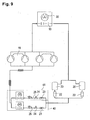
- Fig. 5 shows the basic functional structure of the cooling device according to the invention.
- a first cooling circuit 15 and a second cooling circuit 16 are provided, which are both independently controllable. Both cooling circuits have the same structure.
- Each of these cooling circuits 15, 16 each includes an evaporator 17.
- a coolant that is provided by means of a respective compressor 18, via a respective condenser 19, a collector 20 and a subsequent subcooler 21, a filter drier 22, a sight glass 23, a solenoid valve 24 and an expansion valve 25 is provided.
- Each of these cooling circuits 15, 16 is arranged with a first part 26 in the air treatment part 4 and with a second part 27 in the cooling part 5.
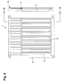
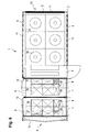
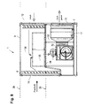
- Fig. 6 shows an upper level 28 and Fig. 7 a lower level 29 of the transportable cooling device 1 wherein the position of the levels 28 and 29 from Fig. 8 can be seen.
- cooling fans 30 are provided in the vertical air flow, the condenser 19 and the subcooler 21 lie.
- a ceiling cutout 31 is provided in the container 2, through the warm air can enter the outside.
- the cooling fans 30 suck their cooling air through the ventilation openings 9.
- At the sand filters 11 thereby coarser particles, which are entrained by the suction, hit down and then fall down, whereby these sand filters 11 then have a self-cleaning effect.
- downstream dust filter are not necessarily required in the air flow and are omitted to improve the efficiency.
- each evaporator 17 is associated with a fan 32. But it is also possible that the evaporator 17 of both cooling circuits 15 and 16 are flowed through by one and the same fan, as is not shown in detail. It would be possible to switch the cooling capacity with the same air flow in two stages. In the illustrated example, however, two air streams are shown via two fans 32, each with separate cooling circuits 15 and 16.
- a fan space 33 is realized by a false ceiling 34. From this fan room 33, the fans 32 suck in the air to be cooled.
- the sand filters i. the blinds 8, which are in the air flow of the fresh air and the circulating air, dust filter 35 downstream of the air flow.
- These are designed as fine dust filters, for example in the dust class EU 3 or EU 4.
- the blinds 8 as a sand filter be educated.
- the dust filter 35 are arranged on the false ceiling 34 in a filter chamber 36 through which the air to be sucked must pass.
- the fans 32 are provided with a suction power, which allows the upstream of these dust filter 35.
- this has the advantage that the negative pressure in the fan chamber 33 can be measured via pressure sensors (not shown). If the negative pressure drops too much, this can be regarded as an indicator that the dust filters 35 are added and require replacement or cleaning.
- a clogging of the dust filter 35 thus at most leads to a reduction of the air power, but not to a damage of the fan 32nd
- the air to be cooled can be provided further via two ways.
- the air can be sucked in as fresh air via the fresh air opening 7.
- a pre-filter consisting of a sand filter, which is realized by the blind 8, and / or a sand filter 37 and a dust filter 35, is provided.
- the amount of fresh air entering can be adjusted by the position of the blind 8.
- the ratio fresh air / circulating air is set immediately.
- the flow resistances are matched to one another in such a way that 100% fresh air is driven in front of the fresh air opening 7 when the blind 8 is fully open. If this shutter 8 is closed, 90% circulating air and 10% fresh air is driven. The 10% are required to ensure an oxygen content of the cooled air and this is set by an incomplete tightness of the blind 8 in front of the fresh air opening 7.
- the air can also be sucked in as circulating air.
- the air intake 12 are connected with pipes to the room to be cooled, so that from this room, the air to be cooled is sucked in as circulating air.
- a mixed operation of fresh air and circulating air is possible.
- FIG. 5 Two separate cooling circuits are shown. Physically, this block diagram can be realized in that two fan spaces 33 are provided.
- a first part 26 preferably a first evaporator 17, which is part 38 of the first cooling circuit 15, with associated fan 32 and filters 35 and 37 arranged.
- a first part 26 preferably a first evaporator 17, which is part 39 of the second cooling circuit 16, with associated fan 32 and filters 35 and 37 arranged.
- cooling fan 30 In the cooling part 5, two compressors 18 are arranged.
- the in Fig. 7 illustrated left compressor 18 is part 38 of the first cooling circuit 15 and the right-hand compressor 18 is part 39 of the second cooling circuit 16. These then the cooling fan 30 can be assigned in groups.
- FIG. 9 illustrated schematic diagram of the two cooling circuits 15 and 16 Fig. 5 not completely separated. Rather, only a first cooling circuit part 40 and a second cooling circuit part 41 are separated from each other. Both cooling circuit parts 40 and 41 include an evaporator 17, which is associated with a fan 32, an expansion valve 25, a solenoid valves 24 and a sight glass 23. The remaining parts of the cooling circuit, in particular or the condenser 19 with the associated cooling fans 30 and the or the compressors 18 are shared by both cooling circuit parts 40 and 41.
- the first cooling circuit part 40 is arranged as a component 38 and the second cooling circuit part as a component 39 each in one of the two fan chambers 33.
- the compressors 18 are arranged in the same way, interconnect only together, so that you do not assign them as part 38 or 39 of the cooling circuits.
- Such a cooling device 1 thus has five separate effect chambers, namely the filter chamber 36 for the first cooling circuit 15 or for the first cooling circuit part 40, the filter chamber 36 for the second cooling circuit 16 or for the second cooling circuit part 41, the fan space 33 for the first cooling circuit 15th or for the first cooling circuit part 40, the fan room 33 for the second cooling circuit 16 or for the second cooling circuit part 41, and the space of the cooling part 5.
Landscapes
- Engineering & Computer Science (AREA)
- Chemical & Material Sciences (AREA)
- Combustion & Propulsion (AREA)
- Mechanical Engineering (AREA)
- General Engineering & Computer Science (AREA)
- Devices That Are Associated With Refrigeration Equipment (AREA)
Abstract
Description
Die Erfindung betrifft eine transportable Kühlvorrichtung mit einer Ansaugöffnung, einem Ausblasstutzen, einem Kühlkreislauf bestehend aus einem Verdampfer, einem Verdichter und einem Verflüssiger. Weiterhin ist ein Lüfter mit einer zur Ansaugöffnung gerichteten Saugseite und einer zu dem Ausblasstutzen gerichteten Druckseite vorgesehen, wobei eine Kühlquelle zwischen der Druckseite des Lüfters und Ausblasstutzen angeordnet ist.The invention relates to a transportable cooling device with a suction opening, a blow-out, a cooling circuit consisting of an evaporator, a compressor and a condenser. Furthermore, a fan is provided with a suction side directed towards the intake opening and a pressure side directed towards the exhaust nozzle, wherein a cooling source is arranged between the pressure side of the fan and exhaust nozzle.
Es ist ein Kühlsystem der Fa. Carrier Rental Systems Germany GmbH bekannt, welches als transportable Kühlvorrichtung ausgebildet ist. Diese besteht aus einem Lufthandhabungsgerät und einem Flüssigkeitskühler. Beide Komponenten sind in Container angeordnete und somit ortsveränderlich ausgebildet.It is a cooling system of the Fa. Carrier Rental Systems Germany GmbH known, which is designed as a portable cooling device. This consists of an air handling device and a liquid cooler. Both components are arranged in containers and thus formed movable.
In dem Flüssigkeitskühler sind die klassischen Einheiten wie Verflüssiger, Verdichter und Verdampfer vorgesehen. Der Verdampfer steht mit einem Sekundär-Kühlmittelkreislauf in Wirkungsverbindung. Dabei wird durch den Verdampfer über einen Wärmetauscher das Kühlmittel des Sekundärkreislaufes gekühlt und mittels einer Pumpe zu dem Lufthandhabungsgerät transportiert. Dort erfolgt über einen weiteren Wärmetauscher die Kühlung der der über Lüfter durch den Wärmetauscher gedrückten Warmluft.In the liquid cooler, the classical units such as condenser, compressor and evaporator are provided. The evaporator is in operative connection with a secondary coolant circuit. In this case, the refrigerant of the secondary circuit is cooled by the evaporator via a heat exchanger and transported by a pump to the air handling device. There, via a further heat exchanger, the cooling of the pressed by fans through the heat exchanger hot air.
Wenn auch dieses System den Vorteil bietet, dass der Flüssigkeitskühler zu dem zu kühlenden Räumen getrennt aufgestellt werden kann, so ist doch festzustellen, dass hier ein gesonderter Pumpensatz erforderlich ist, der zum einen eine Transportbedarf, sowohl hinsichtlich des Raumbedarfes als auch hinsichtlich des Gewichtes, aufweist. Außerdem wird dadurch die Störanfälligkeit erhöht. Dies und die Baugröße der erforderlichen zwei Systemkomponenten limitieren die die Einsatzgebiete einer solchen transportablen Kühlvorrichtung. So wird eine Nutzung eines derartigen Systems in robusten Kriseneinsätzen eingeschränkt. Außerdem wird die gekühlte Luft stets vollständig aus angesaugter Frischluft erzeugt, woraus sich ein hoher Energieaufwand ergibt.Although this system offers the advantage that the liquid cooler can be placed separately to the rooms to be cooled, it should be noted that a separate pump set is required here, which on the one hand requires a transport, both in terms of space and in terms of weight, having. In addition, this increases the susceptibility to interference. This and the size of the required two system components limit the areas of use of such a portable cooling device. Thus, use of such a system in robust crisis operations is limited. In addition, the cooled air is always generated entirely from sucked fresh air, resulting in a high energy consumption.
Es ist somit Aufgabe der Erfindung, eine transportable Kühlvorrichtung anzugeben, deren Herstellungs- und Materialaufwand verringert ist, die einen geringeren Transportaufwand erfordert und auch unter erschwerten Umgebungsbedingungen mit hoher Zuverlässigkeit arbeitet und die eine hohe Energieeffizienz aufweist.It is therefore an object of the invention to provide a portable cooling device whose manufacturing and material costs are reduced, which requires a lower transport cost and also works under difficult environmental conditions with high reliability and has a high energy efficiency.
Diese Aufgabe wird gemäß der Erfindung dadurch gelöst, dass die Kühlquelle direkt durch den Verdampfer gebildet wird und dass der Lüfter und der Kühlkreislauf in ein und demselben Container angeordnet sind. Damit entfällt einerseits ein sekundärer Kühlkreislauf und die damit verbundenen Teile, wie zusätzlicher Pumpen- und Leitungssatz. Dies verringert den Herstellungs- und Materialaufwand. Weiterhin wird der Wirkungsgrad durch den Wegfall des sekundären Kühlkreislaufes verbessert und damit die Energie- bzw. Brennstoffeffizienz verbessert. Andererseits kann die gesamte Vorrichtung mit einem Mal gehandhabt werden. Der Container wird vor Ort aufgestellt und kann nach Verbindung mit dem zu kühlenden Raum sofort ohne weiteren Installationsaufwand in Betrieb genommen werden. Üblicher Weise kann die Vorrichtung mit einem 20-ft-Normcontainer versehen werden, der selbst auch über die erforderlichen Aufnahmemittel für Transport- und Hebezeuge verfügt.This object is achieved according to the invention in that the cooling source is formed directly through the evaporator and that the fan and the cooling circuit are arranged in one and the same container. This eliminates the one hand, a secondary cooling circuit and the associated parts, such as additional pump and wiring harness. This reduces the manufacturing and material costs. Furthermore, the efficiency is improved by the elimination of the secondary cooling circuit and thus improves the energy and fuel efficiency. On the other hand, the entire device can be handled all at once. The container is set up on site and can be put into operation immediately after connection to the room to be cooled without further installation effort. Usually, the device can be provided with a 20-ft standard container, which itself also has the necessary receiving means for transport and lifting equipment.
In einer Ausgestaltung der Erfindung ist vorgesehen, dass der Innenraum des Containers in einen Luftaufbereitungsteil und einen luftseitig von diesem getrennten Kühlteil geteilt ist. Dabei sind in dem Luftaufbereitungsteil ein erster Teil des Kühlkreislaufes mit dem Verdampfer und zusammen mit dem Lüfter und das Kühlteil mit einer Belüftungsöffnung versehen. In dem Kühlteil ist ein zweiter Teil des Kühlkreislaufes, der den Verdichter und den Verflüssiger enthält, angeordnet, wobei der zweite Teil des Kühlkreislaufes mit einem Kühllüfter versehen ist, in dessen Luftstrom der Verflüssiger liegt. Durch diese Teilung wird es möglich, die Luftströme, nämlich den Luftstrom der zu kühlenden Luft und den Luftstrom der der Beseitigung der Abwärme dient, in einfacher Weise getrennt voneinander zu führen. Besondere Rohrleitungen im Inneren des Containers zu Führung der Luftströme werden somit vermieden und auch die Wandflächen des Containers werden optimal für die Anordnung der erforderlichen Öffnungen genutzt.In one embodiment of the invention it is provided that the interior of the container is divided into an air treatment part and an air side of this separate cooling part. In this case, in the air treatment part, a first part of the cooling circuit with the evaporator and together with the Fan and the cooling part provided with a ventilation opening. In the cooling part, a second part of the cooling circuit, which contains the compressor and the condenser, arranged, wherein the second part of the cooling circuit is provided with a cooling fan, in the air flow of the condenser is located. By this division, it is possible, the air currents, namely the air flow of the air to be cooled and the air flow which serves to eliminate the waste heat to lead in a simple manner separated from each other. Special piping inside the container to guide the air currents are thus avoided and the wall surfaces of the container are optimally used for the arrangement of the required openings.
In einer weiteren Ausgestaltung der Erfindung ist eine weitere Teilung vorgesehen, nämlich dergestalt, dass in dem Luftaufbereitungsteil ein Lüfterraum abgeteilt ist. Dieser Lüfterraum ist über ein Staubfilter mit dem übrigen Luftaufbereitungsteil verbunden. In dem Lüfterraum sind der Verdampfer und der Lüfter angeordnet und mit dem Luftauslassstutzen verbunden. In dem übrigen Luftaufbereitungsteil ist die Ansaugöffnung angeordnet. Damit saugt der Lüfter die Luft aus dem Lüfterraum, die sodann über das Staubfilter aus dem übrigen Luftaufbereitungsteil von der Ansaugöffnung, die im übrigen eine Frischluftöffnung oder eine Umluftöffnung oder eine Kombination aus beiden darstellen kann, nachströmt und durch dieses gefiltert wird. Die Erfindung ermöglicht somit den Einsatz von Umluft, d.h. von bereits gekühlter Luft. Durch diese erfindungsgemäße Konstruktion und eine intelligente Steuerung ist es möglich, eine ökonomische und energiesparende Betriebsweise zu realisieren.In a further embodiment of the invention, a further division is provided, namely in such a way that in the air treatment part, a fan room is divided. This fan room is connected via a dust filter with the rest of the air conditioning part. In the fan room, the evaporator and the fan are arranged and connected to the air outlet. In the remaining air treatment part, the suction port is arranged. Thus, the fan sucks the air from the fan room, which then flows through the dust filter from the rest of the air conditioning part of the suction port, which may otherwise constitute a fresh air opening or a recirculation opening or a combination of both, and is filtered by this. The invention thus enables the use of circulating air, i. of already cooled air. By this construction according to the invention and an intelligent control, it is possible to realize an economical and energy saving operation.
In einer Ausgestaltung der Erfindung ist vor der Saugseite des Lüfters ein Filter angeordnet und der Lüfter ist mit einer den Strömungswiderstand des Filters überwindenden Saugleistung versehen. Damit wird es möglich, dass die Anordnung der Filter mit einfachen Mitteln erfolgen kann. Ist nämlich das Filter zugesetzt, wird sich lediglich die Förderleistung des Lüfters verringern, ohne dass dieser selbst Schaden nimmt. Zusätzliche Mittel, die zwingend eine Druckkontrolle zum Leistungsschutz des Lüfters erfordern sind entbehrlich.In one embodiment of the invention, a filter is arranged in front of the suction side of the fan and the fan is provided with a suction force overcoming the flow resistance of the filter. This will make it possible for the Arrangement of the filter can be done with simple means. Namely, if the filter is added, only the capacity of the fan will reduce without this even takes damage. Additional resources that require a pressure control to protect the performance of the fan are unnecessary.
Zur optimalen Filterung der Kühlluft ist in einer Ausgestaltung der Erfindung vorgesehen, dass das Filter ein Staubfilter aufweist.For optimal filtering of the cooling air is provided in one embodiment of the invention that the filter has a dust filter.
Zusätzlich kann es insbesondere beim Einsatz in Wüstengebieten zweckmäßig sein, grobe Partikel von dem Staubfilter fern zu halten, um dieses nicht unnötig zu belasten. Hierzu ist in einer Ausgestaltung der Erfindung vorgesehen, dass das Filter ein Sandfilter aufweist.In addition, it may be useful, especially when used in desert areas, to keep coarse particles away from the dust filter so as not to burden it unnecessarily. For this purpose, it is provided in one embodiment of the invention that the filter has a sand filter.
Zweckmäßiger Weise ist dabei das Staubfilter in Strömungsrichtung hinter dem Sandfilter angeordnet.Appropriately, the dust filter is arranged downstream of the sand filter in the flow direction.
Auch die Überwachung des Zustandes des Filters wird durch den Einsatz eines Lüfters mit einer größeren Saugleistung erleichtert. So ist in einer Ausgestaltung der Erfindung zwischen dem Filter und der Saugseite des Lüfters ein Druckmessfühler angeordnet, der mit einer Druckmesseinrichtung und darüber mit einer Druckanzeigevorrichtung verbunden ist.The monitoring of the condition of the filter is facilitated by the use of a fan with a larger suction power. Thus, in one embodiment of the invention between the filter and the suction side of the fan, a pressure sensor is arranged, which is connected to a pressure measuring device and above with a pressure indicator device.
In einer weiteren Ausgestaltung ist vorgesehen, dass die Belüftungsöffnung mit einem Sandfilter versehen ist. Die Belüftungsöffnungen dienen in erster Linie dem Belüften des Verflüssigers. Hierbei ist es nicht unbedingt erforderlich, die Kühlluft für den Verflüssiger staubfrei zu halten. Allerdings ist ein Fernhalten von Sand, insbesondere für den Einsatz in Wüstengebieten, sehr sinnvoll, um ein Versanden des Innenraumes zu verhindern.In a further embodiment, it is provided that the ventilation opening is provided with a sand filter. The ventilation openings serve primarily to aerate the condenser. In this case, it is not absolutely necessary to keep the cooling air for the condenser dust-free. However, keeping away from sand, especially for use in desert areas, makes great sense to prevent sanding of the interior.
Um den Wartungsaufwand hierbei so gering wie möglich zu halten, ist es zweckmäßig, dass das Sandfilter selbstreinigend ausgebildet ist. Dies kann dadurch realisiert werden, dass das Filter mit Prallplatten versehen ist, gegen die die Sandpartikel, die von der Luftströmung mitgerissen werden, prallen und infolge des Geschwindigkeitsverlustes nach unten fallen.In order to keep the maintenance effort as low as possible, it is expedient that the sand filter self-cleaning is trained. This can be realized by providing the filter with baffles against which the sand particles entrained in the air flow bounce and fall down due to the loss of speed.
Dies kann zweckmäßiger Weise dadurch realisiert werden, dass die Belüftungsöffnung mit einem als Wetterschutzgitter ausgebildeten Sandfilter versehen ist.This can advantageously be realized by providing the ventilation opening with a sand filter designed as a weather protection grid.
Zur Erhöhung oder Variation der Kühlleistung ist in einer weiteren Variante der erfindungsgemäßen Ausgestaltung vorgesehen, einen zweiten Kühlkreislauf anzuordnen, dessen Verdampfer als eine zweite Kühlquelle zwischen der Druckseite des Lüfters und Ausblasstutzen angeordnet ist. Je nach Erfordernis kann dann ein Kühlkreislauf, der andere Kühlkreislauf oder beide zugeschaltet werden. Auch wird es so möglich, eine Redundanz zu schaffen, so dass immer ein Kühlkreislauf betriebsbereit ist, selbst wenn der andere ausfällt.To increase or vary the cooling capacity is provided in a further variant of the embodiment of the invention to arrange a second cooling circuit, the evaporator is arranged as a second cooling source between the pressure side of the fan and Ausblasstutzen. Depending on requirements, then a cooling circuit, the other cooling circuit or both can be switched on. It also makes it possible to create a redundancy, so that always one cooling circuit is ready, even if the other fails.
Hierzu ist es insbesondere zweckmäßig, wenn der Kühlkreislauf und der zweite Kühlkreislauf unabhängig voneinander regelbar sind.For this purpose, it is particularly expedient if the cooling circuit and the second cooling circuit can be controlled independently.
In einer anderen Ausführungsform ist vorgesehen, dass ein zweiter Kühlkreislauf angeordnet ist, dessen Verdampfer als eine Kühlquelle zwischen der Druckseite eines zweiten Lüfters und dessen zugehörigen Ausblasstutzen in dem Luftstrom des zweiten Lüfters des zweiten Kühlkreislaufes angeordnet ist. Somit werden zwei separate Kühlluftströme realisiert, mit denen entweder die Kühlleistung und/oder die Zuverlässigkeit erhöht werden kann.In another embodiment, it is provided that a second cooling circuit is arranged, the evaporator is arranged as a cooling source between the pressure side of a second fan and its associated Ausblasstutzen in the air flow of the second fan of the second cooling circuit. Thus, two separate cooling air flows are realized with which either the cooling capacity and / or the reliability can be increased.
Auch hier ist es zweckmäßig, wenn der Kühlkreislauf und der zweite Kühlkreislauf und/oder der Lüfter und der zweite Lüfter, unabhängig voneinander regelbar sind.Again, it is useful if the cooling circuit and the second cooling circuit and / or the fan and the second fan, are independently controllable.
Die Erfindung soll nachstehend anhand eines Ausführungsbeispieles näher erläutert werden.The invention will be explained below with reference to an exemplary embodiment.
- Fig. 1Fig. 1
- eine Seitenansicht einer erfindungsgemäßen Kühlvorrichtung,a side view of a cooling device according to the invention,
- Fig. 2Fig. 2
- eine gegenüberliegende Seitenansicht der erfindungsgemäßen Kühlvorrichtung,an opposite side view of the cooling device according to the invention,
- Fig. 3Fig. 3
- eine Vorderansicht der erfindungsgemäßen Kühlvorrichtung mit Tür,a front view of the cooling device according to the invention with door,
- Fig. 4Fig. 4
- eine Rückansicht der erfindungsgemäßen Kühlvorrichtung mit Rückwand und Ansauggitter,a rear view of the cooling device according to the invention with the rear wall and intake grille,
- Fig. 5Fig. 5
- ein Prinzipschaltbild der erfindungsgemäßen Kühlvorrichtung,a schematic diagram of the cooling device according to the invention,
- Fig. 6Fig. 6
- eine Schnittdarstellung mit einer Draufsicht auf eine obere Ebene der erfindungsgemäßen Kühlvorrichtung,a sectional view with a plan view of an upper level of the cooling device according to the invention,
- Fig. 7Fig. 7
- eine Schnittdarstellung mit einer Draufsicht auf eine untere Ebene der erfindungsgemäßen Kühlvorrichtung,a sectional view with a plan view of a lower level of the cooling device according to the invention,
- Fig. 8Fig. 8
- eine Schnittdarstellung der erfindungsgemäßen Kühlvorrichtung mit einer Ansicht in Richtung zur Vorderseite unda sectional view of the cooling device according to the invention with a view towards the front and
- Fig. 9Fig. 9
- ein Prinzipschaltbild der erfindungsgemäßen Kühlvorrichtung mit einer gemeinsamen Nutzung des Verflüssigers für beide Kühlkreisläufe.a schematic diagram of the cooling device according to the invention with a common use of the condenser for both cooling circuits.
Wie in
Der Container 2 ist in einen Luftaufbereitungsteil 4 und einen Kühlteil 5 geteilt. Die Teilung verläuft in dem Beispiel links der Servicetür 3The
Die von der in
Der Kühlteil 5 ist mit Belüftungsöffnungen 9 versehen, die einen Eintritt von Frischluft in den Kühlteil 5 ermöglichen.The cooling
Die linke Seite, die in
Im Bereich des Luftaufbereitungsteiles 4 auf der linken Seite sind Luftansaugstutzen 12 vorgesehen, mit denen es möglich ist, den Luftaufbereitungsteil 4 über entsprechende Rohrleitungen mit dem zu belüftenden Raum zu verbinden. Damit wird es möglich, den Luftaufbereitungsteil 4 auch zumindest teilweise mit Umluft zu versorgen. Auch vor diesen Luftansaugstutzen 12 sind Jalousien 8 vorgesehen. Diese können ebenfalls wieder als selbstreinigende Sandfilter fungieren.In the area of the
Das Verhältnis Frischluft/Umluft ist funktional zwischen 10 bis 100% regelbar.The fresh air / recirculated air ratio is functionally adjustable between 10 and 100%.
Weiterhin sind an dieser Seite auch Luftauslassstutzen 13 vorgesehen. An diesen steht gekühlte Zuluft aus dem Luftaufbereitungsteil 4, die dann über entsprechende Rohrleitungen dem zu kühlenden Raum zugeführt werden kann.Furthermore,
Wie in
In
Darin entspannt sich ein Kühlmittel, dass mittels je eines Verdichters 18, über je einen Verflüssiger 19, einen Sammler 20 und einen nachfolgenden Unterkühler 21, ein Filtertrockner 22, ein Schauglas 23, ein Magnetventil 24 und ein Expansionsventil 25 zur Verfügung gestellt wird.Therein, a coolant that is provided by means of a
Jeder dieser Kühlkreisläufe 15, 16 ist mit einem ersten Teil 26 in dem Luftaufbereitungsteil 4 und mit einem zweiten Teil 27 in dem Kühlteil 5 angeordnet.Each of these cooling
Zum Abtransport der Wärme aus den Verflüssigern 19 und den Unterkühlern 21 sind Kühllüfter 30 vorgesehen, in deren vertikalem Luftstrom die Verflüssiger 19 und die Unterkühler 21 liegen. Zur Abluft der Kühllüfter 30 ist in dem Container 2 eine Deckenausschnitt 31 vorgesehen, durch den warme Abluft der ins Freie treten kann. Die Kühllüfter 30 saugen ihre Kühlluft über die Belüftungsöffnungen 9 an. An den Sandfiltern 11 schlagen sich dabei gröbere Partikel, die durch das Ansaugen mitgeführt werden, nieder und fallen sodann nach unten wodurch diese Sandfilter 11 sodann einen Selbstreinigungseffekt aufweisen. Damit wird der Einsatz an Orten, wo zu kühlen ist, aber auch eine hohe Grobpartikelkonzentration anzutreffen ist, wie beispielsweise in Wüstenbereichen, ermöglicht. Hier sind im Luftstrom nachfolgende Staubfilter nicht unbedingt erforderlich und werden zur Verbesserung des Wirkungsgrades weggelassen.For the removal of heat from the
Von dem Luftstrom in dem Kühlteil 5 getrennt ist der Luftstrom in dem Luftaufbereitungsteil 4 organisiert. Dabei ist jedem Verdampfer 17 ein Lüfter 32 zugeordnet. Es ist aber auch möglich, dass die Verdampfer 17 beider Kühlkreisläufe 15 und 16 von ein und demselben Lüfter durchströmt werden, wie dies jedoch nicht näher dargestellt ist. Dabei würde es möglich, die Kühlleistung bei gleichem Luftdurchsatz in zwei Stufen zu schalten. In dem dargestellten Beispiel sind jedoch zwei Luftströme über zwei Lüfter 32 mit jeweils separaten Kühlkreisläufen 15 und 16 dargestellt.Separated from the air flow in the
Wie in
Den Sandfiltern, d.h. den Jalousien 8, die im Luftstrom der Frischluft und der Umluft liegen, sind Staubfilter 35 im Luftstrom nachgeordnet. Diese sind als Feinstaubfilter, beispielsweise in der Staubklasse EU 3 oder EU 4 ausgebildet.The sand filters, i. the
Wie oben erwähnt, können die Jalousien 8 als Sandfilter ausgebildet sein. Es ist jedoch auch möglich, direkte Sandfilter 37 vor den Staubfiltern 35 anzuordnen, wie dies in
Dabei sind die Staubfilter 35 auf der Zwischendecke 34 in einem Filterraum 36 angeordnet, durch die die anzusaugende Luft hindurch treten muss. Dabei sind die Lüfter 32 mit einer Saugleistung versehen, die das Vorschalten dieser Staubfilter 35 erlaubt. Das hat zum einen den Vorteil, dass über nicht näher dargestellte Drucksensoren der Unterdruck in dem Lüfterraum 33 gemessen werden kann. Sinkt der Unterdruck zu stark, kann das als Indikator dafür angesehen werden, dass die Staubfilter 35 zugesetzt sind und einem Auswechseln oder einer Reinigung bedürfen. Zum anderen führt ein Zusetzen der Staubfilter 35 somit allenfalls zu einer Verminderung der Luftleistung, nicht jedoch zu einer Beschädigung der Lüfter 32.The
Die zu kühlende Luft kann im Weiteren über zwei Wege zur Verfügung gestellt werden. Zum einen kann die Luft als Frischluft über die Frischluftöffnung 7 angesaugt werden. Zur Vermeidung des Eintritts von Staub ist hier ein Vorfilter, bestehend aus einem Sandfilter, das durch die Jalousie 8 realisiert wird, und/oder einem Sandfilter 37 und einem Staubfilter 35, vorgesehen. Außerdem kann die Menge des Frischlufteintritts durch die Stellung der Jalousie 8 eingestellt werden. Damit wird sogleich das Verhältnis Frischluft/Umluft eingestellt. Die Strömungswiderstände sind so aufeinander abgestimmt, dass bei voll geöffneter Jalousie 8 vor der Frischluftöffnung 7 100% Frischluft gefahren wird. Wird diese Jalousie 8 geschlossen, wird 90% Umluft und 10% Frischluft gefahren. Die 10% dabei sind zur Gewährleistung eines Sauerstoffanteiles der gekühlten Luft erforderlich und dies wird durch eine nicht vollständige Schließdichtheit der Jalousie 8 vor der Frischluftöffnung 7 eingestellt.The air to be cooled can be provided further via two ways. On the one hand, the air can be sucked in as fresh air via the
Zum anderen kann die Luft auch als Umluft angesaugt werden.On the other hand, the air can also be sucked in as circulating air.
Hierzu werden die Luftansaugstutzen 12 mit Rohrleitungen mit dem zu kühlenden Raum verbunden, so dass aus diesem Raum die zu kühlende Luft als Umluft angesaugt wird. Selbstverständlich ist auch ein Mischbetrieb aus Frischluft und Umluft möglich.For this purpose, the
In
In dem Kühlteil 5 sind zwei Verdichter 18 angeordnet. Der in
Bei dem in
Physisch können die Teile des Prinzipschaltbildes gemäß
Auch wenn nur einer der Kühlkreislaufteile 40 und 41 zur Erzeugung gekühlter Luft verwendet wird, hat es sich gezeigt, dass sich die Energieeffizienz verbessert, auch wenn dabei möglicherweise die Schalthäufigkeit zunimmt.Even if only one of the refrigerating
Eine derartige Kühlvorrichtung 1 weist also fünf voneinander getrennte Wirkungskammern, nämlich den Filterraum 36 für den ersten Kühlkreislauf 15 oder für den ersten Kühlkreislaufteil 40, den Filterraum 36 für den zweiten Kühlkreislauf 16 oder für den zweiten Kühlkreislaufteil 41, den Lüfterraum 33 für den ersten Kühlkreislauf 15 oder für den ersten Kühlkreislaufteil 40, den Lüfterraum 33 für den zweiten Kühlkreislauf 16 oder für den zweiten Kühlkreislaufteil 41, und den Raum des Kühlteiles 5 auf.Such a cooling device 1 thus has five separate effect chambers, namely the
- 11
- transportable Kühlvorrichtungtransportable cooling device
- 22
- ContainerContainer
- 33
- Servicetürservice door
- 44
- LuftaufbereitungsteilAir treatment part
- 55
- Kühlteilrefrigerator
- 66
- Vorderseitefront
- 77
- FrischluftöffnungFresh air opening
- 88th
- Jalousielouvre
- 99
- Belüftungsöffnungventilation opening
- 1010
- Rückseiteback
- 1111
- Sandfiltersand filter
- 1212
- Luftansaugstutzenair intake
- 1313
- Luftauslassstutzenair outlet
- 1414
- Türdoor
- 1515
- erster Kühlkreislauffirst cooling circuit
- 1616
- zweiter Kühlkreislaufsecond cooling circuit
- 1717
- VerdampferEvaporator
- 1818
- Verdichtercompressor
- 1919
- Verflüssigercondenser
- 2020
- Sammlercollector
- 2121
- Unterkühlersubcooler
- 2222
- Filtertrocknerfilter dryer
- 2323
- Schauglassight glass
- 2424
- Magnetventilmagnetic valve
- 2525
- Expansionsventilexpansion valve
- 2626
- erster Teil des Kühlkreislaufesfirst part of the cooling circuit
- 2727
- zweiter Teil des Kühlkreislaufessecond part of the cooling circuit
- 2828
- obere Ebeneupper level
- 2929
- untere Ebenelower level
- 3030
- Kühllüftercooling fan
- 3131
- Deckenausschnittceiling cut
- 3232
- LüfterFan
- 3333
- Lüfterraumfan room
- 3434
- Zwischendeckefalse ceiling
- 3535
- Staubfilterdust filter
- 3636
- Filterraumfilter chamber
- 3737
- Sandfiltersand filter
- 3838
- Bestandteil des ersten Teils des KühlkreislaufesPart of the first part of the cooling circuit
- 3939
- Bestandteil des zweiten Teils des KühlkreislaufesPart of the second part of the cooling circuit
- 4040
- erster Kühlkreislaufteilfirst cooling circuit part
- 4141
- zweiter Kühlkreislaufteilsecond cooling circuit part
Claims (15)
dadurch gekennzeichnet, dass der Innenraum des Containers (2) in einen Luftaufbereitungsteil (4) und einen luftseitig von diesem getrennten Kühlteil (5) geteilt ist, wobei in dem Luftaufbereitungsteil (4) ein erster Teil (26) des Kühlkreislaufes (15; 16) mit dem Verdampfer (17) und zusammen mit dem Lüfter (32) angeordnet ist, das Kühlteil (5) mit einer Belüftungsöffnung (9) versehen ist und in dem Kühlteil (5) ein zweiter Teil (27) des Kühlkreislauf (15; 16), der den Verdichter (18) und den Verflüssiger (19) enthält, angeordnet ist, wobei der zweite Teil (27) des Kühlkreislauf (15; 16) mit einem Kühllüfter (30) versehen ist, in dessen Luftstrom der Verflüssiger (19) liegt.Transportable cooling device according to claim 1,
characterized in that the interior of the container (2) is divided into an air treatment part (4) and a cooling part (5) separated therefrom by the air, wherein in the air treatment part (4) a first part (26) of the cooling circuit (15; 16) with the evaporator (17) and together with the fan (32) is arranged, the cooling part (5) is provided with a ventilation opening (9) and in the cooling part (5) has a second part (27) of the cooling circuit (15; 16) containing the compressor (18) and the condenser (19) is arranged, wherein the second part (27) of the cooling circuit (15; 16) is provided with a cooling fan (30) in the air flow of the condenser (19) ,
dadurch gekennzeichnet, dass in dem Luftaufbereitungsteil (4) ein Lüfterraum (33) abgeteilt ist, der über ein Staubfilter mit dem übrigen Luftaufbereitungsteil (4) verbunden ist und dass in dem Lüfterraum (33) der Verdampfer (17) und der Lüfter (32) angeordnet und mit dem Luftauslassstutzen (13) verbunden sind und in dem übrigen Luftaufbereitungsteil (4) die Ansaugöffnung (7; 12) angeordnet ist.Transportable cooling device according to claim 2,
characterized in that in the air treatment part (4) a fan chamber (33) is divided, which is connected via a dust filter with the rest of the air conditioning part (4) and in that in the fan chamber (33) of the evaporator (17) and the fan (32) and arranged with the air outlet nozzle (13 ) are connected and in the remaining air treatment part (4), the suction port (7; 12) is arranged.
dadurch gekennzeichnet, dass das Filter (8; 35; 37) ein Staubfilter (35; 37)aufweist.Transportable cooling device according to claim 4,
characterized in that the filter (8; 35; 37) comprises a dust filter (35; 37).
dadurch gekennzeichnet, dass das Filter (8; 35; 37) ein Sandfilter (8) aufweistTransportable cooling device according to claim 4 or 5,
characterized in that the filter (8; 35; 37) comprises a sand filter (8)
dadurch gekennzeichnet, dass das Staubfilter (35; 37) in Strömungsrichtung hinter dem Sandfilter (8) angeordnet ist.Transportable cooling device according to claim 6,
characterized in that the dust filter (35, 37) is arranged in the flow direction behind the sand filter (8).
dadurch gekennzeichnet, dass das Sandfilter (11) selbstreinigend ausgebildet ist.Transportable cooling device according to claim 9,
characterized in that the sand filter (11) is self-cleaning.
dadurch gekennzeichnet, dass die Belüftungsöffnung (9) mit einem als Wetterschutzgitter ausgebildeten Sandfilter (11) versehen ist.Transportable cooling device according to claim 9 or 10,
characterized in that the ventilation opening (9) is provided with a designed as a weather protection grit sand filter (11).
dadurch gekennzeichnet, dass der Kühlkreislauf (15) und der zweite Kühlkreislauf (16) unabhängig voneinander regelbar sind.Transportable cooling device according to claim 12,
characterized in that the cooling circuit (15) and the second cooling circuit (16) are independently controllable.
dadurch gekennzeichnet, dass der Kühlkreislauf (15) und der zweite Kühlkreislauf (16) und/oder der Lüfter (32) und der zweite Lüfter, unabhängig voneinander regelbar sind.Transportable cooling device according to claim 14,
characterized in that the cooling circuit (15) and the second cooling circuit (16) and / or the fan (32) and the second fan, are independently controllable.
Priority Applications (1)
| Application Number | Priority Date | Filing Date | Title |
|---|---|---|---|
| EP09154145A EP2226577A1 (en) | 2009-03-02 | 2009-03-02 | Transportable cooling device |
Applications Claiming Priority (1)
| Application Number | Priority Date | Filing Date | Title |
|---|---|---|---|
| EP09154145A EP2226577A1 (en) | 2009-03-02 | 2009-03-02 | Transportable cooling device |
Publications (1)
| Publication Number | Publication Date |
|---|---|
| EP2226577A1 true EP2226577A1 (en) | 2010-09-08 |
Family
ID=40801964
Family Applications (1)
| Application Number | Title | Priority Date | Filing Date |
|---|---|---|---|
| EP09154145A Withdrawn EP2226577A1 (en) | 2009-03-02 | 2009-03-02 | Transportable cooling device |
Country Status (1)
| Country | Link |
|---|---|
| EP (1) | EP2226577A1 (en) |
Cited By (1)
| Publication number | Priority date | Publication date | Assignee | Title |
|---|---|---|---|---|
| CN105928113A (en) * | 2016-06-15 | 2016-09-07 | 上海震业机电有限公司 | Water evaporation cooling system with automatic dust removing function |
Citations (6)
| Publication number | Priority date | Publication date | Assignee | Title |
|---|---|---|---|---|
| DE1301454B (en) | 1962-03-07 | 1969-08-21 | Eigner Otto | Room cooling unit |
| JPS59109731A (en) | 1982-12-14 | 1984-06-25 | Matsushita Seiko Co Ltd | Exhaust heat processor of cooler |
| DE8804702U1 (en) * | 1987-04-17 | 1988-05-19 | Delchi Carrier S.P.A., Villasanta, Milano, It | |
| DE3938875A1 (en) | 1989-11-24 | 1991-05-29 | Behr Gmbh & Co | Mobile air conditioner stores energy in phase-change - medium for subsequent usage in heating water supply |
| US6279333B1 (en) | 2000-03-14 | 2001-08-28 | Industry Heating And Cooling, Inc. | Mobile industrial air cooling apparatus |
| DE20121745U1 (en) | 2001-11-30 | 2003-04-30 | Dornier Gmbh | Modular mobile ventilator and air conditioning modular system for military and civil emergency use |
-
2009
- 2009-03-02 EP EP09154145A patent/EP2226577A1/en not_active Withdrawn
Patent Citations (6)
| Publication number | Priority date | Publication date | Assignee | Title |
|---|---|---|---|---|
| DE1301454B (en) | 1962-03-07 | 1969-08-21 | Eigner Otto | Room cooling unit |
| JPS59109731A (en) | 1982-12-14 | 1984-06-25 | Matsushita Seiko Co Ltd | Exhaust heat processor of cooler |
| DE8804702U1 (en) * | 1987-04-17 | 1988-05-19 | Delchi Carrier S.P.A., Villasanta, Milano, It | |
| DE3938875A1 (en) | 1989-11-24 | 1991-05-29 | Behr Gmbh & Co | Mobile air conditioner stores energy in phase-change - medium for subsequent usage in heating water supply |
| US6279333B1 (en) | 2000-03-14 | 2001-08-28 | Industry Heating And Cooling, Inc. | Mobile industrial air cooling apparatus |
| DE20121745U1 (en) | 2001-11-30 | 2003-04-30 | Dornier Gmbh | Modular mobile ventilator and air conditioning modular system for military and civil emergency use |
Cited By (1)
| Publication number | Priority date | Publication date | Assignee | Title |
|---|---|---|---|---|
| CN105928113A (en) * | 2016-06-15 | 2016-09-07 | 上海震业机电有限公司 | Water evaporation cooling system with automatic dust removing function |
Similar Documents
| Publication | Publication Date | Title |
|---|---|---|
| DE102008054081B4 (en) | Method for conditioning a control cabinet | |
| DE112013005482B4 (en) | refrigeration cycle device | |
| DE202016008946U1 (en) | air conditioner | |
| DE202009002033U1 (en) | Arrangement for conditioning a room | |
| DE3930429A1 (en) | AIR CONDITIONING FOR MOTOR VEHICLES, ESPECIALLY OMNIBUSES | |
| DE102008029922A1 (en) | Air-conditioning device and method for using such a room ventilation device | |
| DE112017005196T5 (en) | Vehicle air conditioning | |
| WO2018024583A1 (en) | Air conditioning device for a motor vehicle | |
| DE3405584C2 (en) | ||
| EP0962374B1 (en) | Ready to fit air conditioning module, especially for railway vehicles | |
| DE4025628C2 (en) | ||
| EP2226577A1 (en) | Transportable cooling device | |
| CH708202A2 (en) | Ventilation system. | |
| DE202013102473U1 (en) | Room air technical (RLT) device for a central air conditioning system | |
| WO2008052735A1 (en) | Cooling module, technical device with a cooling module, and method for internally cooling a technical device | |
| EP2837275A2 (en) | Cooling device for a switch cabinet and a corresponding method | |
| DE19638535C2 (en) | Ventilation system with heat recovery | |
| EP3490825B1 (en) | Air-conditioning device for a motor vehicle and method for the operation thereof | |
| DE202004018206U1 (en) | Climate control assembly has a ventilator with heating and ventilation components e.g. a heat exchanger, compressor | |
| DE102011101347A1 (en) | Refrigerator and/or freezer for use in building or living space, has ventilation system comprising supply air duct and exhaust air duct that are connected to intake port and exhaust port respectively | |
| DE112018005940T5 (en) | air conditioning | |
| EP0890802B1 (en) | Exhaust and ventilation device with regenerative heat recovery | |
| EP2665350B1 (en) | Fan unit for cooling of apparatus, such as electrical/electronic assemblies, equipment and the like | |
| EP3370491A1 (en) | Assembly of a cooling system for cooling at least one server rack in a room | |
| DE112009000657B4 (en) | Method for operating a cooling device and cooling device for carrying out such a method |
Legal Events
| Date | Code | Title | Description |
|---|---|---|---|
| PUAI | Public reference made under article 153(3) epc to a published international application that has entered the european phase |
Free format text: ORIGINAL CODE: 0009012 |
|
| AK | Designated contracting states |
Kind code of ref document: A1 Designated state(s): AT BE BG CH CY CZ DE DK EE ES FI FR GB GR HR HU IE IS IT LI LT LU LV MC MK MT NL NO PL PT RO SE SI SK TR |
|
| AX | Request for extension of the european patent |
Extension state: AL BA RS |
|
| 17P | Request for examination filed |
Effective date: 20110304 |
|
| 17Q | First examination report despatched |
Effective date: 20110330 |
|
| STAA | Information on the status of an ep patent application or granted ep patent |
Free format text: STATUS: THE APPLICATION IS DEEMED TO BE WITHDRAWN |
|
| 18D | Application deemed to be withdrawn |
Effective date: 20151001 |