EP2226569A1 - A cooking oven with at least one cooking chamber - Google Patents
A cooking oven with at least one cooking chamber Download PDFInfo
- Publication number
- EP2226569A1 EP2226569A1 EP09003256A EP09003256A EP2226569A1 EP 2226569 A1 EP2226569 A1 EP 2226569A1 EP 09003256 A EP09003256 A EP 09003256A EP 09003256 A EP09003256 A EP 09003256A EP 2226569 A1 EP2226569 A1 EP 2226569A1
- Authority
- EP
- European Patent Office
- Prior art keywords
- cooking
- cooking oven
- side wall
- identification
- oven according
- Prior art date
- Legal status (The legal status is an assumption and is not a legal conclusion. Google has not performed a legal analysis and makes no representation as to the accuracy of the status listed.)
- Withdrawn
Links
- 238000010411 cooking Methods 0.000 title claims abstract description 72
- 238000001125 extrusion Methods 0.000 description 3
- 238000005286 illumination Methods 0.000 description 2
- 238000004519 manufacturing process Methods 0.000 description 2
- 238000000034 method Methods 0.000 description 1
Images
Classifications
-
- F—MECHANICAL ENGINEERING; LIGHTING; HEATING; WEAPONS; BLASTING
- F24—HEATING; RANGES; VENTILATING
- F24C—DOMESTIC STOVES OR RANGES ; DETAILS OF DOMESTIC STOVES OR RANGES, OF GENERAL APPLICATION
- F24C15/00—Details
- F24C15/16—Shelves, racks or trays inside ovens; Supports therefor
Definitions
- the present invention relates to a cooking oven, in particular a household cooking oven, with at least one cooking chamber according to the preamble of claim 1.
- the inserting devices for receiving a sheet, tray and/or grid are arranged on different levels, so that the food stuff can be prepared in a suitable position within the cooking chamber.
- a typical cooking chamber of a household cooking oven comprises about four or five inserting devices on different levels.
- the best result of the cooking process can be obtained on a preferred level.
- the instruction manuals of cooking ovens and the cookbooks provide an indication of the ideal level for the sheet, tray or grid within the cooking chamber.
- the levels of the inserting devices are not labelled.
- the expression "on the first level” may be understood as the lowest or as the highest level of the cooking chamber. It is not clear, if the levels of the inserting devices are enumerated top down or from the bottom up. A clear correlation is not given in the most cases.
- the DE 10 2006 012 502 A1 describes a cooking oven with a cooking chamber.
- the different levels of the cooking chamber are labelled by identification markings at the oven door, so that the identification markings are visible from both sides of said oven door.
- the user can clearly recognize the denotations of the levels, if the oven door is closed. However, if the oven door is opened, then the correlation between the levels on the one hand and the identification markings at the inner side of the oven door on the other hand is not quite clear.
- the DE 101 25 247 C1 shows a cooking oven with a cooking chamber.
- the different levels of the cooking chamber are labelled by electrically controlled identification markings at the inner side of the cooking chamber.
- these identification markings deliver useable information only in combination with additional information from a display.
- the identification markings are embossed in at least one side wall of the cooking chamber and the identification marking is arranged within a surface section of the side wall, wherein said surface section is inclined to the front side, so that the identification marking is visible from the opening by the user.
- the core of the present invention is the embossed identification markings in the side wall on the one hand and the inclined surface sections with said identification markings on the other hand.
- the embossed identification markings can be easily produced and are robust against heat. If the side wall is made by extrusion, then the identification markings can be embossed within the same production step.
- the side wall of the cooking chamber comprises at least one projection including at least one surface section with the identification marking.
- the side wall with projections allows a compact form of the cooking chamber.
- the side wall of the cooking chamber may additionally comprise projections without identification marking.
- the inserting device is formed by two guiding rails, arranged at the left inner side wall and at the right inner side wall, respectively, on the same level.
- Two guiding rails allow a robust support of the sheet, tray or grid with food stuff.
- the guiding rail is designed as an open channel formed between at least two projections lying upon each other.
- the side wall can be easily produced by extrusion.
- At least one of the side walls comprises at least one vertical channel interrupting at least a part of the guiding rails.
- Said vertical channel may include at least one lamp. The vertical channel with the lamp allows an illumination of several levels.
- At least one surface section with an identification marking is arranged between the opening and the vertical channel and at least one further surface section with an identification marking is arranged between the vertical channel and a rear panel of the cooking chamber. This allows the identification of the levels from several positions in front of the cooking chamber.
- the cooking oven may comprise an oven door with at least one window, so that the identification markings are visible from the outside of the cooking chamber through said window. Thereby the positions of the window and the identification markings may be adapted to each other.
- identification markings are represented by natural numbers, in particular by Arabic numbers. Further, roman numbers can also be used.
- identification markings may be represented by letters. Further, the identification markings may be represented by symbols.
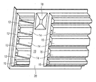
- FIG. 1 shows a perspective view of a left inner side wall 10 of a cooking chamber in a cooking oven according to a preferred embodiment of the present invention.
- the left inner side wall 10 comprises four horizontal guiding rails 12.
- Each guiding rail 12 at the left inner side 10 and a corresponding guiding rail at a right inner side wall form together an inserting device.
- Said four inserting devices are provided to receive a sheet, tray and/or grid.
- the sheet, tray and/or grid are provided for supporting food stuff.
- the guiding rails 12 are formed as open channels within the inner side wall 10. The open side of a said channel is directed to the interior of the cooking chamber. Between the guiding rails 12 there are projections 14 on the inner side wall 10. Said projections 14 define the open channels forming the guiding rails 12.
- the guiding rails 12 as well as the projections 14 are interrupted by a vertical channel 20.
- the vertical channel 20 extends from the top to the bottom of the inner side wall 10.
- the height of the vertical channel 20 corresponds with the heights of the inner side wall 10 and the cooking chamber.
- the width of the vertical channel 20 is about the fourth or the fifth of the depth of the inner side wall 10.
- the vertical channel 20 subdivides the inner side wall 10 into a front portion and a rear portion of said inner side wall 10.
- the width of the front portion is about a fourth of the width of the inner side wall 10.
- the width of the rear portion is about a half of the width of the inner side wall 10.
- a lamp 18 is arranged in the upper portion of the vertical channel 20 .
- the lamp 18 inside the vertical channel 20 allows that the whole cooking chamber can also be illuminated, when one or more sheets or trays with food stuff are inserted between the guiding rails 12.
- the left inner side wall 10 comprises four guiding rails 12 formed as horizontal channels and one vertical channel 20, so that the left inner side wall 10 includes ten projections 14 overall. That side of each projection 14, which is the closest the opening, is denoted as front side of the projection 14.
- the front side of the projection 14 comprises a surface section straightened in such a way, so that said surface section is visible from the opening.
- each surface section which is arranged below a guiding rail 12, an identification marking 16 is embossed.
- the surface section is inclined to the opening of the cooking chamber, so that the identification marking 16 is always visible from the opening by the user.
- the projections 14 in front of the vertical channel 20 as well as the projections 14 behind the vertical channel 20 below the guiding rails 12 comprise a surface section with the embossed identification marking 16. This constellation increases the ability to recognize the designations of the levels.
- the embossed identification markings 16 in the side wall 10 are robust against heat.
- the inclined surface sections with said identification markings 16 allow that the identification markings 16 are also visible from the outside of the closed cooking chamber through a window of the oven door.
- the embossed identification markings 16 can be easily produced. If the side wall 10 of the cooking chamber is made by extrusion, then the identification markings 16 can be embossed within the same production step.
- one or a set of lamps 18 may be arranged within the cooking chamber, so that the identification markings 16 can be optimally illuminated.
- the identification markings 16 are represented by natural Arabic numbers. In a similar way, the identification markings 16 may be represented by natural roman numbers. Further, identification markings 16 may be represented by letters. At last, the identification markings 16 may be represented by arbitrary suitable symbols.
- a right inner side wall of the cooking chamber may be formed mirror-inverted to the left inner side wall.
- each inserting device is labelled by four identification markings 16. Further, this constellation allows an illumination of the cooking chamber form the left side and the right side.
- the right inner side wall of the cooking chamber may be formed mirror-inverted to the left inner side wall, but without the vertical channel 20.
- the cooking oven may comprise an oven door with one or more windows, so that the identification markings 16 are visible from the outside of the cooking chamber through at least on of said windows. Thereby the positions of the windows and the identification markings 16 may be adapted to each other.
Landscapes
- Engineering & Computer Science (AREA)
- Chemical & Material Sciences (AREA)
- Combustion & Propulsion (AREA)
- Mechanical Engineering (AREA)
- General Engineering & Computer Science (AREA)
- Electric Ovens (AREA)
- Electric Stoves And Ranges (AREA)
Abstract
Description
- The present invention relates to a cooking oven, in particular a household cooking oven, with at least one cooking chamber according to the preamble of
claim 1. - In the cooking chamber the inserting devices for receiving a sheet, tray and/or grid are arranged on different levels, so that the food stuff can be prepared in a suitable position within the cooking chamber. On the different levels there are different temperatures and air flow conditions. A typical cooking chamber of a household cooking oven comprises about four or five inserting devices on different levels.
- For a certain kind of food stuff the best result of the cooking process can be obtained on a preferred level. The instruction manuals of cooking ovens and the cookbooks provide an indication of the ideal level for the sheet, tray or grid within the cooking chamber. However, in the most cooking chambers the levels of the inserting devices are not labelled. Thus, it is not exactly clear to the user, on which level the sheet, tray or grid should be inserted into the cooking chamber. For example, the expression "on the first level" may be understood as the lowest or as the highest level of the cooking chamber. It is not clear, if the levels of the inserting devices are enumerated top down or from the bottom up. A clear correlation is not given in the most cases.
- The
DE 10 2006 012 502 A1 describes a cooking oven with a cooking chamber. The different levels of the cooking chamber are labelled by identification markings at the oven door, so that the identification markings are visible from both sides of said oven door. The user can clearly recognize the denotations of the levels, if the oven door is closed. However, if the oven door is opened, then the correlation between the levels on the one hand and the identification markings at the inner side of the oven door on the other hand is not quite clear. - The
DE 101 25 247 C1 shows a cooking oven with a cooking chamber. The different levels of the cooking chamber are labelled by electrically controlled identification markings at the inner side of the cooking chamber. However, these identification markings deliver useable information only in combination with additional information from a display. - It is the object of the present invention to provide a cooking oven with at least one cooking chamber, wherein the user can clearly recognize the designation of the levels of the inserting devices and the complexity of the cooking oven is relative small.
- According to the present invention the identification markings are embossed in at least one side wall of the cooking chamber and the identification marking is arranged within a surface section of the side wall, wherein said surface section is inclined to the front side, so that the identification marking is visible from the opening by the user.
- The core of the present invention is the embossed identification markings in the side wall on the one hand and the inclined surface sections with said identification markings on the other hand. The embossed identification markings can be easily produced and are robust against heat. If the side wall is made by extrusion, then the identification markings can be embossed within the same production step.
- For example, the side wall of the cooking chamber comprises at least one projection including at least one surface section with the identification marking. The side wall with projections allows a compact form of the cooking chamber. The side wall of the cooking chamber may additionally comprise projections without identification marking.
- Preferably, the inserting device is formed by two guiding rails, arranged at the left inner side wall and at the right inner side wall, respectively, on the same level. Two guiding rails allow a robust support of the sheet, tray or grid with food stuff.
- According to the preferred embodiment of the present invention the guiding rail is designed as an open channel formed between at least two projections lying upon each other. Thus, the side wall can be easily produced by extrusion.
- Further, at least one of the side walls comprises at least one vertical channel interrupting at least a part of the guiding rails. Said vertical channel may include at least one lamp. The vertical channel with the lamp allows an illumination of several levels.
- In the preferred embodiment of the present invention at least one surface section with an identification marking is arranged between the opening and the vertical channel and at least one further surface section with an identification marking is arranged between the vertical channel and a rear panel of the cooking chamber. This allows the identification of the levels from several positions in front of the cooking chamber.
- Further, the cooking oven may comprise an oven door with at least one window, so that the identification markings are visible from the outside of the cooking chamber through said window. Thereby the positions of the window and the identification markings may be adapted to each other.
- In the preferred embodiment of the present invention the identification markings are represented by natural numbers, in particular by Arabic numbers. Further, roman numbers can also be used.
- In an alternative embodiment of the present invention the identification markings may be represented by letters. Further, the identification markings may be represented by symbols.
- The invention will be explained in more detail below by means of an exemplary embodiment. Reference is thereby made to the drawing, wherein
- FIG 1
- shows a perspective view of an inner side wall of a cooking chamber in a cooking oven according to a preferred embodiment of the present invention.
-
FIG. 1 shows a perspective view of a leftinner side wall 10 of a cooking chamber in a cooking oven according to a preferred embodiment of the present invention. The leftinner side wall 10 comprises four horizontal guidingrails 12. Each guidingrail 12 at the leftinner side 10 and a corresponding guiding rail at a right inner side wall form together an inserting device. Said four inserting devices are provided to receive a sheet, tray and/or grid. The sheet, tray and/or grid are provided for supporting food stuff. - The guiding
rails 12 are formed as open channels within theinner side wall 10. The open side of a said channel is directed to the interior of the cooking chamber. Between the guidingrails 12 there areprojections 14 on theinner side wall 10. Saidprojections 14 define the open channels forming the guidingrails 12. - In this preferred embodiment the guiding
rails 12 as well as theprojections 14 are interrupted by avertical channel 20. Thevertical channel 20 extends from the top to the bottom of theinner side wall 10. Thus, the height of thevertical channel 20 corresponds with the heights of theinner side wall 10 and the cooking chamber. - In this example, the width of the
vertical channel 20 is about the fourth or the fifth of the depth of theinner side wall 10. Thevertical channel 20 subdivides theinner side wall 10 into a front portion and a rear portion of saidinner side wall 10. The width of the front portion is about a fourth of the width of theinner side wall 10. The width of the rear portion is about a half of the width of theinner side wall 10. - In the upper portion of the vertical channel 20 a
lamp 18 is arranged. Thelamp 18 inside thevertical channel 20 allows that the whole cooking chamber can also be illuminated, when one or more sheets or trays with food stuff are inserted between the guidingrails 12. - In
FIG 1 the leftinner side wall 10 comprises four guidingrails 12 formed as horizontal channels and onevertical channel 20, so that the leftinner side wall 10 includes tenprojections 14 overall. That side of eachprojection 14, which is the closest the opening, is denoted as front side of theprojection 14. The front side of theprojection 14 comprises a surface section straightened in such a way, so that said surface section is visible from the opening. - In each surface section, which is arranged below a guiding
rail 12, an identification marking 16 is embossed. The surface section is inclined to the opening of the cooking chamber, so that the identification marking 16 is always visible from the opening by the user. - In this example, the
projections 14 in front of thevertical channel 20 as well as theprojections 14 behind thevertical channel 20 below the guiding rails 12 comprise a surface section with the embossed identification marking 16. This constellation increases the ability to recognize the designations of the levels. - The embossed
identification markings 16 in theside wall 10 are robust against heat. The inclined surface sections with saididentification markings 16 allow that theidentification markings 16 are also visible from the outside of the closed cooking chamber through a window of the oven door. The embossedidentification markings 16 can be easily produced. If theside wall 10 of the cooking chamber is made by extrusion, then theidentification markings 16 can be embossed within the same production step. - Further, one or a set of
lamps 18 may be arranged within the cooking chamber, so that theidentification markings 16 can be optimally illuminated. - In this example, the
identification markings 16 are represented by natural Arabic numbers. In a similar way, theidentification markings 16 may be represented by natural roman numbers. Further,identification markings 16 may be represented by letters. At last, theidentification markings 16 may be represented by arbitrary suitable symbols. - For example, a right inner side wall of the cooking chamber may be formed mirror-inverted to the left inner side wall. In this case, each inserting device is labelled by four
identification markings 16. Further, this constellation allows an illumination of the cooking chamber form the left side and the right side. - According to another example, the right inner side wall of the cooking chamber may be formed mirror-inverted to the left inner side wall, but without the
vertical channel 20. - At last, the cooking oven may comprise an oven door with one or more windows, so that the
identification markings 16 are visible from the outside of the cooking chamber through at least on of said windows. Thereby the positions of the windows and theidentification markings 16 may be adapted to each other. -
- 10
- side wall
- 12
- guiding rail
- 14
- projection
- 16
- identification marking
- 18
- lamp
- 20
- vertical channel
Claims (12)
- A cooking oven, in particular a household cooking oven, with at least one cooking chamber comprising a number of inserting devices on different levels and an opening at its front side, wherein said inserting device is provided for receiving a sheet, tray or grid supporting food stuff and each inserting device is labelled by at least one identification marking (16) in order to identify the level by a user,
characterized in that
the identification markings (16) are embossed in at least one side wall (10) of the cooking chamber and the identification marking (16) is arranged within a surface section of the side wall (10), wherein said surface section is inclined to the front side, so that the identification marking (16) is visible from the opening by the user. - The cooking oven according to claim 1,
characterized in that
the side wall (10) of the cooking chamber comprises at least one projection (14) including at least one surface section with the identification marking (14). - The cooking oven according to claim 1 or 2,
characterized in that
the inserting device is formed by two guiding rails (12), arranged at the left inner side wall (10) and at the right inner side wall (10), respectively, on the same level. - The cooking oven according to claim 3,
characterized in that
the guiding rail (12) is designed as an open channel formed between at least two projections (14) lying upon each other. - The cooking oven according to any one of the preceding
claims,
characterized in that
at least one of the side walls (10) comprises at least one vertical channel (20) interrupting at least a part of the guiding rails (12). - The cooking oven according to claim 5,
characterized in that
the vertical channel (20) includes at least one lamp (18). - The cooking oven according to claim 5 or 6,
characterized in that
at least one surface section with an identification marking (14) is arranged between the opening and the vertical channel (20) and at least one further surface section with an identification marking (14) is arranged between the vertical channel (20) and a rear panel of the cooking chamber. - The cooking oven according to any one of the preceding claims,
characterized in that
the cooking oven comprises an oven door with at least one window, so that the identification markings (14) are visible from the outside of the cooking chamber through said window. - The cooking oven according to claim 8,
characterized in that
the positions of the window and the identification markings (16) are adapted to each other. - The cooking oven according to any one of the preceding claims,
characterized in that
the identification markings (14) are represented by natural numbers. - The cooking oven according to any one of the preceding claims,
characterized in that
the identification markings (14) are represented by letters. - The cooking oven according to any one of the preceding claims,
characterized in that
the identification markings (14) are represented by symbols.
Priority Applications (1)
| Application Number | Priority Date | Filing Date | Title |
|---|---|---|---|
| EP09003256A EP2226569A1 (en) | 2009-03-06 | 2009-03-06 | A cooking oven with at least one cooking chamber |
Applications Claiming Priority (1)
| Application Number | Priority Date | Filing Date | Title |
|---|---|---|---|
| EP09003256A EP2226569A1 (en) | 2009-03-06 | 2009-03-06 | A cooking oven with at least one cooking chamber |
Publications (1)
| Publication Number | Publication Date |
|---|---|
| EP2226569A1 true EP2226569A1 (en) | 2010-09-08 |
Family
ID=40940303
Family Applications (1)
| Application Number | Title | Priority Date | Filing Date |
|---|---|---|---|
| EP09003256A Withdrawn EP2226569A1 (en) | 2009-03-06 | 2009-03-06 | A cooking oven with at least one cooking chamber |
Country Status (1)
| Country | Link |
|---|---|
| EP (1) | EP2226569A1 (en) |
Cited By (1)
| Publication number | Priority date | Publication date | Assignee | Title |
|---|---|---|---|---|
| EP4624807A1 (en) * | 2024-03-25 | 2025-10-01 | WELBILT Deutschland GmbH | Suspension rack for inserting food carriers, food treatment device and method for operating the food treatment device |
Citations (6)
| Publication number | Priority date | Publication date | Assignee | Title |
|---|---|---|---|---|
| US5111028A (en) * | 1989-09-11 | 1992-05-05 | White Consolidated Industries, Inc. | Method and control arrangement for cooking appliances |
| EP0981027A1 (en) * | 1998-08-14 | 2000-02-23 | Brandt Cooking | Device to assist the positioning of bakery products in an oven |
| DE10125247C1 (en) | 2001-05-23 | 2002-12-12 | Miele & Cie | Household appliance with a cooking space |
| DE10340879A1 (en) * | 2003-09-04 | 2005-03-31 | BSH Bosch und Siemens Hausgeräte GmbH | Muffle for an oven has bearing unit with front bearing member made from different surface material than second bearing member in order to withstand greater strain and loads |
| DE10349315A1 (en) * | 2003-10-23 | 2005-05-25 | BSH Bosch und Siemens Hausgeräte GmbH | Baking oven with lifting bottom plate has support posts with level markings to control relative setting of baking trays |
| DE102006012502A1 (en) | 2006-03-16 | 2007-09-20 | Electrolux Home Products Corporation N.V. | Cooking oven |
-
2009
- 2009-03-06 EP EP09003256A patent/EP2226569A1/en not_active Withdrawn
Patent Citations (6)
| Publication number | Priority date | Publication date | Assignee | Title |
|---|---|---|---|---|
| US5111028A (en) * | 1989-09-11 | 1992-05-05 | White Consolidated Industries, Inc. | Method and control arrangement for cooking appliances |
| EP0981027A1 (en) * | 1998-08-14 | 2000-02-23 | Brandt Cooking | Device to assist the positioning of bakery products in an oven |
| DE10125247C1 (en) | 2001-05-23 | 2002-12-12 | Miele & Cie | Household appliance with a cooking space |
| DE10340879A1 (en) * | 2003-09-04 | 2005-03-31 | BSH Bosch und Siemens Hausgeräte GmbH | Muffle for an oven has bearing unit with front bearing member made from different surface material than second bearing member in order to withstand greater strain and loads |
| DE10349315A1 (en) * | 2003-10-23 | 2005-05-25 | BSH Bosch und Siemens Hausgeräte GmbH | Baking oven with lifting bottom plate has support posts with level markings to control relative setting of baking trays |
| DE102006012502A1 (en) | 2006-03-16 | 2007-09-20 | Electrolux Home Products Corporation N.V. | Cooking oven |
Cited By (1)
| Publication number | Priority date | Publication date | Assignee | Title |
|---|---|---|---|---|
| EP4624807A1 (en) * | 2024-03-25 | 2025-10-01 | WELBILT Deutschland GmbH | Suspension rack for inserting food carriers, food treatment device and method for operating the food treatment device |
Similar Documents
| Publication | Publication Date | Title |
|---|---|---|
| US6789861B1 (en) | Support system for cooking items in a baking oven | |
| EP2840323B1 (en) | System and method for mounting undercabinet ventilation hood | |
| RU2017144233A (en) | Convection oven with removable air chambers | |
| WO2011117037A1 (en) | Cooker | |
| DE102006061739A1 (en) | Muffel for baking-oven, has lighting device with light units arranged for illuminating top and bottom of subspaces, where light units for illuminating one subspace are activatable independent of light units for illuminating other subspaces | |
| EP2128526A1 (en) | Oven, especially domestic oven | |
| EP1631123A3 (en) | Microwave oven with bar code scanner | |
| EP1748255A3 (en) | Electric oven | |
| CN116457612A (en) | Household cooking appliance | |
| KR20130011487A (en) | Drawer unit and electric oven comprising the same | |
| DE102012224034A1 (en) | Lighting device for cooking appliances | |
| EP2390585B1 (en) | An oven cavity for a cooking oven | |
| EP2469190A1 (en) | A cooking hob including an upper part and a base part | |
| DE102009001093B4 (en) | Home appliance for food preparation and method for operating such a domestic appliance | |
| EP2246632A1 (en) | Support for extractable baking trays and/or baking grids | |
| EP1260770A1 (en) | Household appliance with cooking chamber | |
| ES2224491T3 (en) | CABINET FOR DOMESTIC APPLIANCES. | |
| US861689A (en) | Sign. | |
| EP1835232A2 (en) | Baking oven | |
| US9476597B1 (en) | Adjustable oven | |
| KR200385021Y1 (en) | Support plate of cooking vessel which is affixed in cooking device | |
| US20090293857A1 (en) | Domestic Appliance and a Cookable Product Holding Device Therefor | |
| EP2520866B1 (en) | Oven | |
| PL2037184T3 (en) | Convection oven | |
| AU2003280273A1 (en) | Device for heating foodstuff with hot air |
Legal Events
| Date | Code | Title | Description |
|---|---|---|---|
| PUAI | Public reference made under article 153(3) epc to a published international application that has entered the european phase |
Free format text: ORIGINAL CODE: 0009012 |
|
| 17P | Request for examination filed |
Effective date: 20100112 |
|
| AK | Designated contracting states |
Kind code of ref document: A1 Designated state(s): AT BE BG CH CY CZ DE DK EE ES FI FR GB GR HR HU IE IS IT LI LT LU LV MC MK MT NL NO PL PT RO SE SI SK TR |
|
| AX | Request for extension of the european patent |
Extension state: AL BA RS |
|
| RAP1 | Party data changed (applicant data changed or rights of an application transferred) |
Owner name: ELECTROLUX HOME PRODUCTS CORPORATION N.V. |
|
| AKX | Designation fees paid |
Designated state(s): AT BE BG CH CY CZ DE DK EE ES FI FR GB GR HR HU IE IS IT LI LT LU LV MC MK MT NL NO PL PT RO SE SI SK TR |
|
| RAP1 | Party data changed (applicant data changed or rights of an application transferred) |
Owner name: ELECTROLUX HOME PRODUCTS CORPORATION N.V. |
|
| STAA | Information on the status of an ep patent application or granted ep patent |
Free format text: STATUS: THE APPLICATION IS DEEMED TO BE WITHDRAWN |
|
| 18D | Application deemed to be withdrawn |
Effective date: 20141001 |