EP2226562A2 - Injection device for a turbomachine - Google Patents
Injection device for a turbomachine Download PDFInfo
- Publication number
- EP2226562A2 EP2226562A2 EP10155270A EP10155270A EP2226562A2 EP 2226562 A2 EP2226562 A2 EP 2226562A2 EP 10155270 A EP10155270 A EP 10155270A EP 10155270 A EP10155270 A EP 10155270A EP 2226562 A2 EP2226562 A2 EP 2226562A2
- Authority
- EP
- European Patent Office
- Prior art keywords
- combustor
- combustion air
- injection device
- turbomachine
- transition piece
- Prior art date
- Legal status (The legal status is an assumption and is not a legal conclusion. Google has not performed a legal analysis and makes no representation as to the accuracy of the status listed.)
- Withdrawn
Links
- 238000002347 injection Methods 0.000 title claims abstract description 43
- 239000007924 injection Substances 0.000 title claims abstract description 43
- 238000002485 combustion reaction Methods 0.000 claims abstract description 61
- 230000007704 transition Effects 0.000 claims abstract description 26
- 230000003750 conditioning effect Effects 0.000 claims abstract description 18
- 230000007246 mechanism Effects 0.000 claims abstract description 18
- 239000000567 combustion gas Substances 0.000 claims abstract description 14
- 230000001143 conditioned effect Effects 0.000 claims description 10
- 238000000034 method Methods 0.000 claims description 8
- 239000007789 gas Substances 0.000 description 7
- 239000000203 mixture Substances 0.000 description 6
- 238000010790 dilution Methods 0.000 description 5
- 239000012895 dilution Substances 0.000 description 5
- 230000000712 assembly Effects 0.000 description 4
- 238000000429 assembly Methods 0.000 description 4
- 239000000446 fuel Substances 0.000 description 4
- 238000001816 cooling Methods 0.000 description 3
- 238000004891 communication Methods 0.000 description 2
- 230000004075 alteration Effects 0.000 description 1
- 238000010276 construction Methods 0.000 description 1
- 230000002708 enhancing effect Effects 0.000 description 1
- 230000003116 impacting effect Effects 0.000 description 1
- 238000006467 substitution reaction Methods 0.000 description 1
Images



Classifications
-
- F—MECHANICAL ENGINEERING; LIGHTING; HEATING; WEAPONS; BLASTING
- F23—COMBUSTION APPARATUS; COMBUSTION PROCESSES
- F23R—GENERATING COMBUSTION PRODUCTS OF HIGH PRESSURE OR HIGH VELOCITY, e.g. GAS-TURBINE COMBUSTION CHAMBERS
- F23R3/00—Continuous combustion chambers using liquid or gaseous fuel
- F23R3/02—Continuous combustion chambers using liquid or gaseous fuel characterised by the air-flow or gas-flow configuration
- F23R3/04—Air inlet arrangements
-
- F—MECHANICAL ENGINEERING; LIGHTING; HEATING; WEAPONS; BLASTING
- F23—COMBUSTION APPARATUS; COMBUSTION PROCESSES
- F23R—GENERATING COMBUSTION PRODUCTS OF HIGH PRESSURE OR HIGH VELOCITY, e.g. GAS-TURBINE COMBUSTION CHAMBERS
- F23R3/00—Continuous combustion chambers using liquid or gaseous fuel
- F23R3/02—Continuous combustion chambers using liquid or gaseous fuel characterised by the air-flow or gas-flow configuration
- F23R3/04—Air inlet arrangements
- F23R3/045—Air inlet arrangements using pipes
Definitions
- the subject matter disclosed herein relates to the art of turbomachines and, more particularly, to an injection device for a turbomachine.
- gas turbine engines combust a fuel/air mixture that releases heat energy to form a high temperature gas stream.
- the high temperature gas stream is channeled to a turbine via a hot gas path.
- the turbine converts thermal energy from the high temperature gas stream to mechanical energy that rotates a turbine shaft.
- the turbine may be used in a variety of applications, such as for providing power to a pump or an electrical generator.
- turbomachines In a gas turbine, engine efficiency increases with proper combustion of an air/fuel mixture. Enhancing combustion mixing and dilution results in an enhancement of engine efficiency.
- Certain turbomachines employ a series of mixing and dilution passages arranged in the combustion liner. A portion of a combustion airstream passes as a jet flow into the combustion liner (or transition piece). The jet flows are employed to enhance mixing of combustion gases so as to enhance combustion efficiency, and for dilution, to enhance a profile/pattern factor of the combustion.
- a turbomachine includes a compressor, a combustor including a first end operatively connected to the compressor and a second end, a transition piece mounted to the second end of the combustor, and at least one injection device mounted to one of the combustor and the transition piece.
- the at least one injection device includes a first end portion that extends to a second end portion through an intermediate portion.
- the intermediate portion includes a flow conditioning mechanism. Combustion air from the compressor enters the first end portion passes through the flow conditioning mechanism and into the one of the combustion liner and transition piece.
- the flow conditioning mechanism creates an air flow disturbance in the combustion air to promote mixing of combustion gases.
- a method of injecting combustion air into a turbomachine includes generating combustion air at a compressor portion of the turbomachine, guiding the combustion air to at least one injection device mounted to one of a combustor and a transition piece portion of the turbomachine, passing the combustion air into a first end portion of the at least one injection device, guiding the combustion air through a flow conditioning mechanism arranged in the at least one injection device to establish a conditioned combustion air flow, and directing the conditioned combustion air flow into the one of the combustor and the transition piece.
- Turbomachine 2 includes a compressor 4 and a combustor assembly 5 having at least one combustor 6 provided with an injection nozzle assembly housing 8.
- Turbomachine 2 also includes a turbine 10 and a common compressor/turbine shaft 12.
- the present invention is not limited to any one particular engine and may be used in connection with other turbomachines.
- combustor 6 is coupled in flow communication with compressor 4 and turbine 10.
- Compressor 4 includes a diffuser 22 and a compressor discharge plenum 24 that are coupled in flow communication with each other.
- Combustor 6 also includes an end cover 30 positioned at a first end thereof, and a cap member 34.
- Combustor 6 further includes a plurality of pre-mixers or injection nozzle assemblies, two of which are indicated at 38 and 39.
- combustor 6 includes a combustor casing 46 and a combustor liner 47. As shown, combustor liner 47 is positioned radially inward from combustor casing 46 so as to define a combustion chamber 48.
- An annular combustion chamber cooling passage 49 is defined between combustor casing 46 and combustor liner 47.
- Combustor 6 is coupled to turbomachine 2 through a transition piece 55.
- Transition piece 55 channels combustion gases generated in combustion chamber 48 downstream towards a first stage turbine nozzle 62.
- transition piece 55 includes an inner wall 64 and an outer wall 65.
- Outer wall 65 includes a plurality of openings 66 that lead to an annular passage 68 defined between inner wall 64 and outer wall 65.
- Inner wall 64 defines a guide cavity 72 that extends between combustion chamber 48 and turbine 10.
- fuel is passed to injector assemblies 38 and 39 to mix with the compressed air to form a combustible mixture.
- the combustible mixture is channeled to combustion chamber 48 and ignited to form combustion gases.
- the combustion gases are then channeled to turbine 10. Thermal energy from the combustion gases is converted to mechanical rotational energy that is employed to drive compressor/turbine shaft 12.
- turbine 10 drives compressor 4 via compressor/turbine shaft 12 (shown in Figure 1 ).
- compressor 4 rotates, compressed air is discharged into diffuser 22 as indicated by associated arrows.
- a majority of the compressed air discharged from compressor 4 is channeled through compressor discharge plenum 24 towards combustor 6. Any remaining compressed air is channeled for use in cooling engine components.
- Compressed air within discharge plenum 24 is channeled into transition piece 55 via outer wall openings 66 and into annular passage 68.
- the compressed air is then channeled from annular passage 68 through annular combustion chamber cooling passage 49 and to injection nozzle assemblies 38 and 39.
- the fuel and air are mixed to form the combustible mixture.
- the combustible mixture is ignited to form combustion gases within combustion chamber 48.
- Combustor casing 47 facilitates shielding combustion chamber 48 and its associated combustion processes from the outside environment such as, for example, surrounding turbine components.
- the combustion gases are channeled from combustion chamber 48 through guide cavity 72 and towards turbine nozzle 62.
- the hot gases impacting first stage turbine nozzle 62 create a rotational force that ultimately produces work from turbomachine 2.
- turbomachine 2 includes a plurality of injection devices 90, 91 and 93, 94.
- Injection devices 90 and 91 are mounted to combustion liner 47 and are arranged so as to enhance mixing of combustion gases in combustion chamber 48, while injection devices 93 and 94 are arranged on inner wall 64 of transition piece 55 and are arranged so as to facilitate dilution of the combustion gases passing into first turbine stage 62.
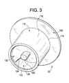
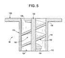
- FIGS. 3-5 reference will now be made to FIGS. 3-5 in describing injection device 90 with an understanding that the remaining injection devices 91, 93 and 94 are similarly formed.
- injection device 90 includes a main body 110 having a first end portion 112 that extends to a second end portion 114 through an intermediate portion 116.
- a circular flange 120 is mounted to second end portion 114.
- Flange 120 provides structure to secure injection device 90 to turbomachine 2. More specifically, flange 120 is welded, or otherwise attached to, for example, combustion liner 47 so that main body 110 projects into combustion chamber 48. Alternatively, flange 120 is welded or otherwise attached to transition piece 55 such that main body 110 projects into guide cavity 72.
- the particular location of injection device 90 depends upon design parameters as well as desired mixing attributes.
- injection device 90 includes a flow conditioning mechanism 124.
- Flow conditioning mechanism 124 is configured to create a disturbance in combustion air passing through injection device 90.
- flow conditioning mechanism 124 includes a central, axial post 130 about which extends a turbulator member 132.
- Turbulator member 132 includes a first end 134 that extends to a second end 135 along a helical flow path 140.
- Helical flow path 140 extends between first and second end portions of main body 110.
- the flow conditioning mechanism may include concentric rings, raised ridges or other forms of protuberances, and or recesses that impart a disturbance to the air flow.
- the particular location and mounting of the injection device can vary depending upon design parameters and desired flow characteristics.
Landscapes
- Engineering & Computer Science (AREA)
- Chemical & Material Sciences (AREA)
- Combustion & Propulsion (AREA)
- Mechanical Engineering (AREA)
- General Engineering & Computer Science (AREA)
- Structures Of Non-Positive Displacement Pumps (AREA)
Abstract
Description
- The subject matter disclosed herein relates to the art of turbomachines and, more particularly, to an injection device for a turbomachine.
- In general, gas turbine engines combust a fuel/air mixture that releases heat energy to form a high temperature gas stream. The high temperature gas stream is channeled to a turbine via a hot gas path. The turbine converts thermal energy from the high temperature gas stream to mechanical energy that rotates a turbine shaft. The turbine may be used in a variety of applications, such as for providing power to a pump or an electrical generator.
- In a gas turbine, engine efficiency increases with proper combustion of an air/fuel mixture. Enhancing combustion mixing and dilution results in an enhancement of engine efficiency. Certain turbomachines employ a series of mixing and dilution passages arranged in the combustion liner. A portion of a combustion airstream passes as a jet flow into the combustion liner (or transition piece). The jet flows are employed to enhance mixing of combustion gases so as to enhance combustion efficiency, and for dilution, to enhance a profile/pattern factor of the combustion.
- According to one aspect of the invention, a turbomachine includes a compressor, a combustor including a first end operatively connected to the compressor and a second end, a transition piece mounted to the second end of the combustor, and at least one injection device mounted to one of the combustor and the transition piece. The at least one injection device includes a first end portion that extends to a second end portion through an intermediate portion. The intermediate portion includes a flow conditioning mechanism. Combustion air from the compressor enters the first end portion passes through the flow conditioning mechanism and into the one of the combustion liner and transition piece. The flow conditioning mechanism creates an air flow disturbance in the combustion air to promote mixing of combustion gases.
- According to another aspect of the invention, a method of injecting combustion air into a turbomachine includes generating combustion air at a compressor portion of the turbomachine, guiding the combustion air to at least one injection device mounted to one of a combustor and a transition piece portion of the turbomachine, passing the combustion air into a first end portion of the at least one injection device, guiding the combustion air through a flow conditioning mechanism arranged in the at least one injection device to establish a conditioned combustion air flow, and directing the conditioned combustion air flow into the one of the combustor and the transition piece.
- These and other advantages and features will become more apparent from the following description taken in conjunction with the drawings.
- There follows a detailed description of embodiments of the invention by way of example only with reference to the accompanying drawings, in which:
-
FIG. 1 is a partial cross-sectional view of a turbomachine including an injection device in accordance with an exemplary embodiment; -
FIG 2 is partial, cross-sectional view of a combustor portion of the turbomachine ofFIG. 1 ; -
FIG 3 is a bottom right perspective view of an injection device in accordance with an exemplary embodiment; -
FIG. 4 is a top right perspective view of the injection device ofFIG. 3 ; and -
FIG. 5 is cross-sectional side view of the injection device ofFIG. 3 . - With reference to
FIG. 1 , a turbomachine constructed in accordance with exemplary embodiments of the invention is generally indicated at 2.Turbomachine 2 includes a compressor 4 and acombustor assembly 5 having at least onecombustor 6 provided with an injectionnozzle assembly housing 8.Turbomachine 2 also includes aturbine 10 and a common compressor/turbine shaft 12. Notably, the present invention is not limited to any one particular engine and may be used in connection with other turbomachines. - As best shown in
FIG. 2 ,combustor 6 is coupled in flow communication with compressor 4 andturbine 10. Compressor 4 includes adiffuser 22 and acompressor discharge plenum 24 that are coupled in flow communication with each other. Combustor 6 also includes anend cover 30 positioned at a first end thereof, and acap member 34.Combustor 6 further includes a plurality of pre-mixers or injection nozzle assemblies, two of which are indicated at 38 and 39. In addition,combustor 6 includes acombustor casing 46 and acombustor liner 47. As shown,combustor liner 47 is positioned radially inward fromcombustor casing 46 so as to define acombustion chamber 48. An annular combustionchamber cooling passage 49 is defined betweencombustor casing 46 andcombustor liner 47. Combustor 6 is coupled toturbomachine 2 through atransition piece 55.Transition piece 55 channels combustion gases generated incombustion chamber 48 downstream towards a firststage turbine nozzle 62. Towards that end,transition piece 55 includes aninner wall 64 and anouter wall 65.Outer wall 65 includes a plurality ofopenings 66 that lead to anannular passage 68 defined betweeninner wall 64 andouter wall 65.Inner wall 64 defines aguide cavity 72 that extends betweencombustion chamber 48 andturbine 10. - During operation, air flows through compressor 4, is compressed, and passed to
combustor 6 and, more specifically, toinjector assemblies injector assemblies combustion chamber 48 and ignited to form combustion gases. The combustion gases are then channeled toturbine 10. Thermal energy from the combustion gases is converted to mechanical rotational energy that is employed to drive compressor/turbine shaft 12. - More specifically,
turbine 10 drives compressor 4 via compressor/turbine shaft 12 (shown inFigure 1 ). As compressor 4 rotates, compressed air is discharged intodiffuser 22 as indicated by associated arrows. In the exemplary embodiment, a majority of the compressed air discharged from compressor 4 is channeled throughcompressor discharge plenum 24 towardscombustor 6. Any remaining compressed air is channeled for use in cooling engine components. Compressed air withindischarge plenum 24 is channeled intotransition piece 55 viaouter wall openings 66 and intoannular passage 68. The compressed air is then channeled fromannular passage 68 through annular combustionchamber cooling passage 49 and to injection nozzle assemblies 38 and 39. The fuel and air are mixed to form the combustible mixture. The combustible mixture is ignited to form combustion gases withincombustion chamber 48.Combustor casing 47 facilitatesshielding combustion chamber 48 and its associated combustion processes from the outside environment such as, for example, surrounding turbine components. The combustion gases are channeled fromcombustion chamber 48 throughguide cavity 72 and towardsturbine nozzle 62. The hot gases impacting firststage turbine nozzle 62 create a rotational force that ultimately produces work fromturbomachine 2. At this point it should be understood that the above-described construction is presented for a more complete understanding of exemplary embodiments of the invention. - In order to enhance combustion efficiency,
turbomachine 2 includes a plurality ofinjection devices Injection devices combustion liner 47 and are arranged so as to enhance mixing of combustion gases incombustion chamber 48, whileinjection devices inner wall 64 oftransition piece 55 and are arranged so as to facilitate dilution of the combustion gases passing intofirst turbine stage 62. As eachinjection device FIGS. 3-5 in describinginjection device 90 with an understanding that theremaining injection devices - In accordance with the exemplary embodiment shown,
injection device 90 includes amain body 110 having afirst end portion 112 that extends to asecond end portion 114 through anintermediate portion 116. Acircular flange 120 is mounted tosecond end portion 114.Flange 120 provides structure to secureinjection device 90 toturbomachine 2. More specifically,flange 120 is welded, or otherwise attached to, for example,combustion liner 47 so thatmain body 110 projects intocombustion chamber 48. Alternatively,flange 120 is welded or otherwise attached to transitionpiece 55 such thatmain body 110 projects intoguide cavity 72. As noted above, the particular location ofinjection device 90 depends upon design parameters as well as desired mixing attributes. - In further accordance with the exemplary embodiment,
injection device 90 includes aflow conditioning mechanism 124.Flow conditioning mechanism 124 is configured to create a disturbance in combustion air passing throughinjection device 90. In the exemplary embodiment shown,flow conditioning mechanism 124 includes a central,axial post 130 about which extends aturbulator member 132.Turbulator member 132 includes afirst end 134 that extends to asecond end 135 along ahelical flow path 140.Helical flow path 140 extends between first and second end portions ofmain body 110. With this arrangement, air enteringinjection device 90 passes alonghelical flow path 140.Helical flow path 140 initiates a disturbance that establishes a swirled airflow. The swirled airflow is then passed intocombustion chamber 48 to facilitate additional mixing of combustion gases contained therein. Alternatively, the swirled airflow is passed intoguide cavity 72 to increase dilution of the combustion gases and further enhance efficiency. - At this point it should be understood that while the exemplary embodiment depicts the flow conditioning mechanism as having a helical flow path, various other geometries may also be employed. That is, the flow conditioning mechanism may include concentric rings, raised ridges or other forms of protuberances, and or recesses that impart a disturbance to the air flow. In addition, it should be understood that the particular location and mounting of the injection device can vary depending upon design parameters and desired flow characteristics.
- While the invention has been described in detail in connection with only a limited number of embodiments, it should be readily understood that the invention is not limited to such disclosed embodiments. Rather, the invention can be modified to incorporate any number of variations, alterations, substitutions or equivalent arrangements not heretofore described, but which are commensurate with the spirit and scope of the invention. Additionally, while various embodiments of the invention have been described, it is to be understood that aspects of the invention may include only some of the described embodiments. Accordingly, the invention is not to be seen as limited by the foregoing description, but is only limited by the scope of the appended claims.
Claims (15)
- A turbomachine (2) comprising:a compressor (4);a combustor (6) including a first end operatively connected to the compressor and a second end;a transition piece (55) mounted to the second end of the combustor (6); andat least one injection device (90) mounted to one of the combustor (6) and the transition piece (55), the at least one injection device (90) including a first end portion (112) that extends to a second end portion (114) through an intermediate portion (116), the intermediate portion (116) including a flow conditioning mechanism (124), wherein combustion air from the compressor (4) enters the first end portion (112) passes through the flow conditioning mechanism (124) and into the one of the combustion liner (6) and transition piece (55), the flow conditioning mechanism (124) creating an air flow disturbance in the combustion air to promote mixing of combustion gases.
- The turbomachine (2) according to claim 1, wherein the flow conditioning mechanism (124) is a turbulator (132) mounted within the at least one injection device (90).
- The turbomachine (2) according to claim 2, wherein the turbulator (132) includes a helical flow path (140).
- The turbomachine (2) according to any of the preceding claims, wherein the at least one injection device (90) is mounted to the combustor (6).
- The turbomachine (2) according to any of claims 1 to 3, wherein the at least one injection device (90) is mounted to the transition piece (55).
- The turbomachine (2) according to any of the preceding claims, wherein the at least one injection device (90) comprises a plurality of injection devices (90-91 and 93-94) arranged along the one of the combustor (6) and the transition piece (55).
- The turbomachine (2) according to any of the preceding claims, wherein the first end portion (112) of the at least one injection device (90) includes a flange (120).
- The turbomachine (2) according to any of the preceding claims, wherein the at least one injection device (90) is welded to the one of the combustor (6) and the transition piece (55).
- The turbomachine (2) according to any of the preceding claims, further comprising: a combustion liner (47) mounted within the combustor (6), the at least one injection device (90) being mounted to the combustion liner (47).
- A method of injecting combustion air into a turbomachine, the method comprising:generating combustion air at a compressor portion of the turbomachine;guiding the combustion air to at least one injection device mounted to one of a combustor and a transition piece portion of the turbomachine;passing the combustion air into a first end portion of the at least one injection device;guiding the combustion air through a flow conditioning mechanism arranged in the at least one injection device to establish a conditioned combustion air flow; anddirecting the conditioned combustion air flow into the one of the combustor and the transition piece.
- The method of claim 10, wherein guiding the combustion air through the flow conditioning mechanism comprises passing the combustion air flow through a turbulator member arranged within the at least one injection device.
- The method of claim 11, wherein passing the combustion air flow through a turbulator member comprises flowing the combustion air flow along a helical flow path, the helical flow path swirling the combustion air flow.
- The method of claim 10, wherein directing the conditioned combustion air flow into the one of the combustor and the transition piece includes directing the conditioned combustion air into the combustor.
- The method of claim 13, wherein directing the conditioned combustion air flow into the combustor comprises directing the conditioned combustion air through a combustion liner portion of the combustor.
- The method of claim 10, wherein directing the conditioned combustion air flow into the one of the combustor and the transition piece comprises directing the conditioned combustion air into the transition piece.
Applications Claiming Priority (1)
| Application Number | Priority Date | Filing Date | Title |
|---|---|---|---|
| US12/399,536 US20100223930A1 (en) | 2009-03-06 | 2009-03-06 | Injection device for a turbomachine |
Publications (2)
| Publication Number | Publication Date |
|---|---|
| EP2226562A2 true EP2226562A2 (en) | 2010-09-08 |
| EP2226562A3 EP2226562A3 (en) | 2014-07-02 |
Family
ID=42237308
Family Applications (1)
| Application Number | Title | Priority Date | Filing Date |
|---|---|---|---|
| EP10155270.1A Withdrawn EP2226562A3 (en) | 2009-03-06 | 2010-03-03 | Injection device for a turbomachine |
Country Status (4)
| Country | Link |
|---|---|
| US (1) | US20100223930A1 (en) |
| EP (1) | EP2226562A3 (en) |
| JP (1) | JP2010210229A (en) |
| CN (1) | CN101876452A (en) |
Cited By (3)
| Publication number | Priority date | Publication date | Assignee | Title |
|---|---|---|---|---|
| WO2016043614A3 (en) * | 2014-08-29 | 2016-06-16 | Micula Viorel | Modular system for swirly driving and controlled orientability of hot air flows |
| EP3039340A4 (en) * | 2013-08-30 | 2016-08-24 | United Technologies Corp | CONTRAST ROLLED DILUTION PASSAGES FOR GAS TURBINE ENGINE COMBUSTION CHAMBER |
| EP2657611A3 (en) * | 2012-04-27 | 2017-11-22 | General Electric Company | System for supplying fuel to a combustor |
Families Citing this family (11)
| Publication number | Priority date | Publication date | Assignee | Title |
|---|---|---|---|---|
| US9243507B2 (en) * | 2012-01-09 | 2016-01-26 | General Electric Company | Late lean injection system transition piece |
| US9097424B2 (en) * | 2012-03-12 | 2015-08-04 | General Electric Company | System for supplying a fuel and working fluid mixture to a combustor |
| US9506359B2 (en) | 2012-04-03 | 2016-11-29 | General Electric Company | Transition nozzle combustion system |
| US9212823B2 (en) * | 2012-09-06 | 2015-12-15 | General Electric Company | Systems and methods for suppressing combustion driven pressure fluctuations with a premix combustor having multiple premix times |
| US9222673B2 (en) * | 2012-10-09 | 2015-12-29 | General Electric Company | Fuel nozzle and method of assembling the same |
| US9217373B2 (en) * | 2013-02-27 | 2015-12-22 | General Electric Company | Fuel nozzle for reducing modal coupling of combustion dynamics |
| WO2015030927A1 (en) * | 2013-08-30 | 2015-03-05 | United Technologies Corporation | Contoured dilution passages for a gas turbine engine combustor |
| EP3060850B1 (en) | 2013-10-24 | 2020-05-13 | United Technologies Corporation | Circumferentially and axially staged annular combustor for gas turbine engine combustor |
| WO2015061217A1 (en) | 2013-10-24 | 2015-04-30 | United Technologies Corporation | Circumferentially and axially staged can combustor for gas turbine engine |
| US9976743B2 (en) * | 2014-07-03 | 2018-05-22 | United Technologies Corporation | Dilution hole assembly |
| CN116658932B (en) * | 2022-02-18 | 2025-09-16 | 通用电气公司 | Combustor liner with dilution openings having swirl vanes |
Family Cites Families (19)
| Publication number | Priority date | Publication date | Assignee | Title |
|---|---|---|---|---|
| US1153805A (en) * | 1914-04-30 | 1915-09-14 | Karl Macdonald | Spray-nozzle. |
| DE1778149A1 (en) * | 1968-04-02 | 1971-07-29 | Buchmueller Hans Joachim | Tube nozzle for gas burner |
| US3872664A (en) * | 1973-10-15 | 1975-03-25 | United Aircraft Corp | Swirl combustor with vortex burning and mixing |
| US3899882A (en) * | 1974-03-27 | 1975-08-19 | Westinghouse Electric Corp | Gas turbine combustor basket cooling |
| US3981142A (en) * | 1974-04-01 | 1976-09-21 | General Motors Corporation | Ceramic combustion liner |
| US3920187A (en) * | 1974-05-24 | 1975-11-18 | Porta Test Mfg | Spray head |
| US4590769A (en) * | 1981-01-12 | 1986-05-27 | United Technologies Corporation | High-performance burner construction |
| JPS6066021A (en) * | 1983-09-21 | 1985-04-16 | Nissan Motor Co Ltd | Fuel injection valve of combustor in gas turbine |
| US4887432A (en) * | 1988-10-07 | 1989-12-19 | Westinghouse Electric Corp. | Gas turbine combustion chamber with air scoops |
| US4944149A (en) * | 1988-12-14 | 1990-07-31 | General Electric Company | Combustor liner with air staging for NOx control |
| JPH02183721A (en) * | 1989-01-06 | 1990-07-18 | Hitachi Ltd | Gas turbine combustor |
| US5241818A (en) * | 1989-07-13 | 1993-09-07 | Sundstrand Corporation | Fuel injector for a gas turbine engine |
| JP2950720B2 (en) * | 1994-02-24 | 1999-09-20 | 株式会社東芝 | Gas turbine combustion device and combustion control method therefor |
| DE4441235A1 (en) * | 1994-11-19 | 1996-05-23 | Abb Management Ag | Combustion chamber with multi-stage combustion |
| US6494044B1 (en) * | 1999-11-19 | 2002-12-17 | General Electric Company | Aerodynamic devices for enhancing sidepanel cooling on an impingement cooled transition duct and related method |
| US6484505B1 (en) * | 2000-02-25 | 2002-11-26 | General Electric Company | Combustor liner cooling thimbles and related method |
| US6331110B1 (en) * | 2000-05-25 | 2001-12-18 | General Electric Company | External dilution air tuning for dry low NOx combustors and methods therefor |
| US6449956B1 (en) * | 2001-04-09 | 2002-09-17 | General Electric Company | Bypass air injection method and apparatus for gas turbines |
| US7000396B1 (en) * | 2004-09-02 | 2006-02-21 | General Electric Company | Concentric fixed dilution and variable bypass air injection for a combustor |
-
2009
- 2009-03-06 US US12/399,536 patent/US20100223930A1/en not_active Abandoned
-
2010
- 2010-03-02 JP JP2010044834A patent/JP2010210229A/en active Pending
- 2010-03-03 EP EP10155270.1A patent/EP2226562A3/en not_active Withdrawn
- 2010-03-08 CN CN2010101395537A patent/CN101876452A/en active Pending
Non-Patent Citations (1)
| Title |
|---|
| None |
Cited By (3)
| Publication number | Priority date | Publication date | Assignee | Title |
|---|---|---|---|---|
| EP2657611A3 (en) * | 2012-04-27 | 2017-11-22 | General Electric Company | System for supplying fuel to a combustor |
| EP3039340A4 (en) * | 2013-08-30 | 2016-08-24 | United Technologies Corp | CONTRAST ROLLED DILUTION PASSAGES FOR GAS TURBINE ENGINE COMBUSTION CHAMBER |
| WO2016043614A3 (en) * | 2014-08-29 | 2016-06-16 | Micula Viorel | Modular system for swirly driving and controlled orientability of hot air flows |
Also Published As
| Publication number | Publication date |
|---|---|
| US20100223930A1 (en) | 2010-09-09 |
| EP2226562A3 (en) | 2014-07-02 |
| JP2010210229A (en) | 2010-09-24 |
| CN101876452A (en) | 2010-11-03 |
Similar Documents
| Publication | Publication Date | Title |
|---|---|---|
| EP2226562A2 (en) | Injection device for a turbomachine | |
| EP2211111B1 (en) | Bundled multi-tube injection nozzle assembly for a turbomachine | |
| US8695322B2 (en) | Thermally decoupled can-annular transition piece | |
| US8925324B2 (en) | Turbomachine including a mixing tube element having a vortex generator | |
| CN110822477B (en) | Dilution structure for gas turbine engine combustor | |
| US8161750B2 (en) | Fuel nozzle for a turbomachine | |
| EP2405201B1 (en) | Injection nozzle for a turbomachine | |
| CN103453554B (en) | For the fuel injection assemblies and its assemble method that are used in turbogenerator | |
| US20110107769A1 (en) | Impingement insert for a turbomachine injector | |
| US8297059B2 (en) | Nozzle for a turbomachine | |
| EP2541146A2 (en) | Turbomachine combustor assembly including a vortex modification system | |
| CN101307723A (en) | Method and apparatus for facilitating cooling of a turbine engine | |
| KR102049042B1 (en) | Fuel nozzle assembly, combustor and gas turbine having the same | |
| US20110162377A1 (en) | Turbomachine nozzle | |
| EP2383517A2 (en) | Fluid cooled injection nozzle assembly for a gas turbomachine | |
| EP2565541A2 (en) | Injection nozzle assembly for a gas turbomachine | |
| US20180195723A1 (en) | Burner for a gas turbine | |
| US20150338101A1 (en) | Turbomachine combustor including a combustor sleeve baffle | |
| US20150028133A1 (en) | Enhanced Mixing Tube Elements | |
| EP2385305A2 (en) | Turbomachine injection nozzle assembly |
Legal Events
| Date | Code | Title | Description |
|---|---|---|---|
| PUAI | Public reference made under article 153(3) epc to a published international application that has entered the european phase |
Free format text: ORIGINAL CODE: 0009012 |
|
| AK | Designated contracting states |
Kind code of ref document: A2 Designated state(s): AT BE BG CH CY CZ DE DK EE ES FI FR GB GR HR HU IE IS IT LI LT LU LV MC MK MT NL NO PL PT RO SE SI SK SM TR |
|
| AX | Request for extension of the european patent |
Extension state: AL BA ME RS |
|
| PUAL | Search report despatched |
Free format text: ORIGINAL CODE: 0009013 |
|
| AK | Designated contracting states |
Kind code of ref document: A3 Designated state(s): AT BE BG CH CY CZ DE DK EE ES FI FR GB GR HR HU IE IS IT LI LT LU LV MC MK MT NL NO PL PT RO SE SI SK SM TR |
|
| AX | Request for extension of the european patent |
Extension state: AL BA ME RS |
|
| RIC1 | Information provided on ipc code assigned before grant |
Ipc: F23R 3/04 20060101AFI20140526BHEP |
|
| STAA | Information on the status of an ep patent application or granted ep patent |
Free format text: STATUS: THE APPLICATION IS DEEMED TO BE WITHDRAWN |
|
| 18D | Application deemed to be withdrawn |
Effective date: 20141001 |