EP2226467A2 - Method of maintaining gas turbine engine components - Google Patents
Method of maintaining gas turbine engine components Download PDFInfo
- Publication number
- EP2226467A2 EP2226467A2 EP10250111A EP10250111A EP2226467A2 EP 2226467 A2 EP2226467 A2 EP 2226467A2 EP 10250111 A EP10250111 A EP 10250111A EP 10250111 A EP10250111 A EP 10250111A EP 2226467 A2 EP2226467 A2 EP 2226467A2
- Authority
- EP
- European Patent Office
- Prior art keywords
- component
- gas turbine
- turbine engine
- engine
- serviceable
- Prior art date
- Legal status (The legal status is an assumption and is not a legal conclusion. Google has not performed a legal analysis and makes no representation as to the accuracy of the status listed.)
- Granted
Links
- 238000000034 method Methods 0.000 title claims abstract description 22
- 239000012530 fluid Substances 0.000 claims abstract description 18
- 239000000463 material Substances 0.000 claims abstract description 11
- 238000001816 cooling Methods 0.000 claims description 11
- 239000003082 abrasive agent Substances 0.000 claims description 8
- 238000002485 combustion reaction Methods 0.000 claims description 3
- 239000006227 byproduct Substances 0.000 claims description 2
- 239000007788 liquid Substances 0.000 claims description 2
- 238000005507 spraying Methods 0.000 claims 1
- 239000000243 solution Substances 0.000 description 21
- 239000007789 gas Substances 0.000 description 10
- 238000001125 extrusion Methods 0.000 description 6
- 238000012423 maintenance Methods 0.000 description 6
- 238000003491 array Methods 0.000 description 4
- 238000013461 design Methods 0.000 description 4
- 230000015572 biosynthetic process Effects 0.000 description 3
- 239000000567 combustion gas Substances 0.000 description 3
- 238000009499 grossing Methods 0.000 description 3
- 230000006835 compression Effects 0.000 description 2
- 238000007906 compression Methods 0.000 description 2
- 239000000446 fuel Substances 0.000 description 2
- TWNQGVIAIRXVLR-UHFFFAOYSA-N oxo(oxoalumanyloxy)alumane Chemical compound O=[Al]O[Al]=O TWNQGVIAIRXVLR-UHFFFAOYSA-N 0.000 description 2
- 239000012459 cleaning agent Substances 0.000 description 1
- 238000004891 communication Methods 0.000 description 1
- 238000011010 flushing procedure Methods 0.000 description 1
- 230000000977 initiatory effect Effects 0.000 description 1
- 238000012986 modification Methods 0.000 description 1
- 230000004048 modification Effects 0.000 description 1
- 230000006911 nucleation Effects 0.000 description 1
- 238000010899 nucleation Methods 0.000 description 1
- 230000003647 oxidation Effects 0.000 description 1
- 238000007254 oxidation reaction Methods 0.000 description 1
- 238000005498 polishing Methods 0.000 description 1
- 239000000047 product Substances 0.000 description 1
- 239000012487 rinsing solution Substances 0.000 description 1
- 230000003746 surface roughness Effects 0.000 description 1
- XLYOFNOQVPJJNP-UHFFFAOYSA-N water Substances O XLYOFNOQVPJJNP-UHFFFAOYSA-N 0.000 description 1
Images

Classifications
-
- F—MECHANICAL ENGINEERING; LIGHTING; HEATING; WEAPONS; BLASTING
- F01—MACHINES OR ENGINES IN GENERAL; ENGINE PLANTS IN GENERAL; STEAM ENGINES
- F01D—NON-POSITIVE DISPLACEMENT MACHINES OR ENGINES, e.g. STEAM TURBINES
- F01D5/00—Blades; Blade-carrying members; Heating, heat-insulating, cooling or antivibration means on the blades or the members
- F01D5/005—Repairing methods or devices
-
- F—MECHANICAL ENGINEERING; LIGHTING; HEATING; WEAPONS; BLASTING
- F01—MACHINES OR ENGINES IN GENERAL; ENGINE PLANTS IN GENERAL; STEAM ENGINES
- F01D—NON-POSITIVE DISPLACEMENT MACHINES OR ENGINES, e.g. STEAM TURBINES
- F01D25/00—Component parts, details, or accessories, not provided for in, or of interest apart from, other groups
- F01D25/002—Cleaning of turbomachines
-
- F—MECHANICAL ENGINEERING; LIGHTING; HEATING; WEAPONS; BLASTING
- F05—INDEXING SCHEMES RELATING TO ENGINES OR PUMPS IN VARIOUS SUBCLASSES OF CLASSES F01-F04
- F05D—INDEXING SCHEME FOR ASPECTS RELATING TO NON-POSITIVE-DISPLACEMENT MACHINES OR ENGINES, GAS-TURBINES OR JET-PROPULSION PLANTS
- F05D2230/00—Manufacture
- F05D2230/10—Manufacture by removing material
-
- F—MECHANICAL ENGINEERING; LIGHTING; HEATING; WEAPONS; BLASTING
- F05—INDEXING SCHEMES RELATING TO ENGINES OR PUMPS IN VARIOUS SUBCLASSES OF CLASSES F01-F04
- F05D—INDEXING SCHEME FOR ASPECTS RELATING TO NON-POSITIVE-DISPLACEMENT MACHINES OR ENGINES, GAS-TURBINES OR JET-PROPULSION PLANTS
- F05D2230/00—Manufacture
- F05D2230/80—Repairing, retrofitting or upgrading methods
-
- F—MECHANICAL ENGINEERING; LIGHTING; HEATING; WEAPONS; BLASTING
- F05—INDEXING SCHEMES RELATING TO ENGINES OR PUMPS IN VARIOUS SUBCLASSES OF CLASSES F01-F04
- F05D—INDEXING SCHEME FOR ASPECTS RELATING TO NON-POSITIVE-DISPLACEMENT MACHINES OR ENGINES, GAS-TURBINES OR JET-PROPULSION PLANTS
- F05D2250/00—Geometry
- F05D2250/60—Structure; Surface texture
- F05D2250/62—Structure; Surface texture smooth or fine
-
- Y—GENERAL TAGGING OF NEW TECHNOLOGICAL DEVELOPMENTS; GENERAL TAGGING OF CROSS-SECTIONAL TECHNOLOGIES SPANNING OVER SEVERAL SECTIONS OF THE IPC; TECHNICAL SUBJECTS COVERED BY FORMER USPC CROSS-REFERENCE ART COLLECTIONS [XRACs] AND DIGESTS
- Y10—TECHNICAL SUBJECTS COVERED BY FORMER USPC
- Y10T—TECHNICAL SUBJECTS COVERED BY FORMER US CLASSIFICATION
- Y10T29/00—Metal working
- Y10T29/45—Scale remover or preventor
- Y10T29/4506—Scale remover or preventor for hollow workpiece
- Y10T29/4511—Interior surface
-
- Y—GENERAL TAGGING OF NEW TECHNOLOGICAL DEVELOPMENTS; GENERAL TAGGING OF CROSS-SECTIONAL TECHNOLOGIES SPANNING OVER SEVERAL SECTIONS OF THE IPC; TECHNICAL SUBJECTS COVERED BY FORMER USPC CROSS-REFERENCE ART COLLECTIONS [XRACs] AND DIGESTS
- Y10—TECHNICAL SUBJECTS COVERED BY FORMER USPC
- Y10T—TECHNICAL SUBJECTS COVERED BY FORMER US CLASSIFICATION
- Y10T29/00—Metal working
- Y10T29/45—Scale remover or preventor
- Y10T29/4533—Fluid impingement
- Y10T29/4544—Liquid jet
-
- Y—GENERAL TAGGING OF NEW TECHNOLOGICAL DEVELOPMENTS; GENERAL TAGGING OF CROSS-SECTIONAL TECHNOLOGIES SPANNING OVER SEVERAL SECTIONS OF THE IPC; TECHNICAL SUBJECTS COVERED BY FORMER USPC CROSS-REFERENCE ART COLLECTIONS [XRACs] AND DIGESTS
- Y10—TECHNICAL SUBJECTS COVERED BY FORMER USPC
- Y10T—TECHNICAL SUBJECTS COVERED BY FORMER US CLASSIFICATION
- Y10T29/00—Metal working
- Y10T29/45—Scale remover or preventor
- Y10T29/4533—Fluid impingement
- Y10T29/455—Airblast
-
- Y—GENERAL TAGGING OF NEW TECHNOLOGICAL DEVELOPMENTS; GENERAL TAGGING OF CROSS-SECTIONAL TECHNOLOGIES SPANNING OVER SEVERAL SECTIONS OF THE IPC; TECHNICAL SUBJECTS COVERED BY FORMER USPC CROSS-REFERENCE ART COLLECTIONS [XRACs] AND DIGESTS
- Y10—TECHNICAL SUBJECTS COVERED BY FORMER USPC
- Y10T—TECHNICAL SUBJECTS COVERED BY FORMER US CLASSIFICATION
- Y10T29/00—Metal working
- Y10T29/49—Method of mechanical manufacture
- Y10T29/49316—Impeller making
- Y10T29/49318—Repairing or disassembling
-
- Y—GENERAL TAGGING OF NEW TECHNOLOGICAL DEVELOPMENTS; GENERAL TAGGING OF CROSS-SECTIONAL TECHNOLOGIES SPANNING OVER SEVERAL SECTIONS OF THE IPC; TECHNICAL SUBJECTS COVERED BY FORMER USPC CROSS-REFERENCE ART COLLECTIONS [XRACs] AND DIGESTS
- Y10—TECHNICAL SUBJECTS COVERED BY FORMER USPC
- Y10T—TECHNICAL SUBJECTS COVERED BY FORMER US CLASSIFICATION
- Y10T29/00—Metal working
- Y10T29/49—Method of mechanical manufacture
- Y10T29/49316—Impeller making
- Y10T29/4932—Turbomachine making
-
- Y—GENERAL TAGGING OF NEW TECHNOLOGICAL DEVELOPMENTS; GENERAL TAGGING OF CROSS-SECTIONAL TECHNOLOGIES SPANNING OVER SEVERAL SECTIONS OF THE IPC; TECHNICAL SUBJECTS COVERED BY FORMER USPC CROSS-REFERENCE ART COLLECTIONS [XRACs] AND DIGESTS
- Y10—TECHNICAL SUBJECTS COVERED BY FORMER USPC
- Y10T—TECHNICAL SUBJECTS COVERED BY FORMER US CLASSIFICATION
- Y10T29/00—Metal working
- Y10T29/49—Method of mechanical manufacture
- Y10T29/49718—Repairing
- Y10T29/49721—Repairing with disassembling
- Y10T29/49723—Repairing with disassembling including reconditioning of part
- Y10T29/49725—Repairing with disassembling including reconditioning of part by shaping
- Y10T29/49726—Removing material
Definitions
- This application relates generally to maintaining a used gas turbine engine component to extend the life of the used component, wherein fluid carrying an abrasive is used to smooth a surface of the used component.
- Gas turbine engines are known and typically include multiple sections, such as a fan section, a compression section, a combustor section, a turbine section, and an exhaust nozzle section.
- the engine includes blade arrays mounted for a rotation about an engine axis.
- the blade arrays include multiple individual blades that extend radially from a mounting platform to a blade tip. Rotating the blade arrays compresses air in the compression section. The compressed air mixes with fuel and is combusted in the combustor section. The products of combustion expand to rotatably drive blade arrays in the turbine section.
- the engine also includes vane sections having multiple individual blades that guide airflow though the engine. Operating the engine fatigues components of the engine. The components often roughen in areas of high stress as they fatigue, a process which if left unchecked can proceed until cracks initiate in the components.
- An example method of maintaining a serviceable component of a gas turbine engine includes selecting a used component, moving a fluid that entrains an abrasive material against a surface of the used component, and removing material from the used component using the abrasive material. In one example, the method moves the abrasive material against the surface of the used component when the used component is installed within the gas turbine engine.
- An example maintained used component of a gas turbine engine has a surface at least partially formed by an abrasive material entrained by a fluid.
- the surface is smoother than a fatigued surface of the component that is at least partially formed by operating the gas turbine engine.
- Figure 1 schematically illustrates an example gas turbine engine 10 including (in serial flow communication) a fan section 14, a low-pressure compressor 18, a high-pressure compressor 22, a combustor 26, a high-pressure turbine 30, and a low-pressure turbine 34.
- the gas turbine engine 10 is circumferentially disposed about an engine centerline X.
- air is pulled into the gas turbine engine 10 by the fan section 14, pressurized by the compressors 18 and 22, mixed with fuel, and burned in the combustor 26.
- the turbines 30 and 34 extract energy from the hot combustion gases flowing from the combustor 26.
- the high-pressure turbine 30 utilizes the extracted energy from the hot combustion gases to power the high-pressure compressor 22 through a high speed shaft 38.
- the low-pressure turbine 34 utilizes the extracted energy from the hot combustion gases to power the low-pressure compressor 18 and the fan section 14 through a low speed shaft 42.
- the examples described in this disclosure are not limited to the two-spool architecture described and may be used in other architectures, such as a single-spool axial design, a three-spool axial design, and still other architectures. That is, there are various types of engines that could benefit from the examples disclosed herein, which are not limited to the design shown.
- an example serviceable component 50 of the engine 10 includes a plurality of internal walls 54 establishing cooling channels 58 that are configured to communicate a cooling flow of air through the serviceable component 50 when the engine 10 is operating.
- the flow of air moves from the cooling channels 58 through a plurality of film cooling holes 62 established in an outer shell 66 of the serviceable component 50.
- the serviceable component 50 is a used blade of the engine 10.
- Other examples of the serviceable component 50 include used vanes, used disks, etc.
- the serviceable component 50 is generally described as any component of the engine 10 that is susceptible to fatigue crack initiation due to surface roughness.
- a dashed line 74 represents a former surface of the serviceable component 50, which, in this example, represents the surface of the serviceable component 50 when the serviceable component 50 was manufactured and prior to using the serviceable component 50 within the engine 10.
- Using the serviceable component 50 thus wears the former surface to the fatigued surface 70.
- the more the serviceable component 50 is used the rougher the fatigued surface 70 becomes.
- the fatigued surface 70 being rougher than the former surface means, in this example, that there is more variation in the fatigued surface 70 than in the former surface.
- the fatigued surface 70 includes an extrusion 78 corresponding to a portion of the fatigued surface 70 that extends past the former surface, and an intrusion 82 corresponding to a portion of the fatigued surface 70 extending away from the former surface. Relative differences between a position of the extrusion 78 and a position of the intrusion 82 represent variation in the fatigued surface 70.
- the roughness of the fatigued surface 70 can undesirably facilitate crack formation in the serviceable component 50.
- the roughness of the fatigued surface 70 is microscopic. The roughness in the figures has been exaggerated in this example for clarity.
- the fatigued surface 70 is also an internal surface of the serviceable component 50 in this example.
- the fatigued surface 70 is an external surface of the serviceable component 50 or a surface of another component of the engine 10.
- Compressor disks are an example of the serviceable component 50 having external surfaces that are fatigued.
- the maintained surface being smoother than the fatigued surface 70 means generally that there is less variation in the maintained surface than in the fatigued surface 70.
- both the extrusions 78 and the intrusions 82 are removed from the serviceable component 50 to establish the maintained surface.
- the size of the extrusions 78 and the intrusions 82 is reduced to establish the maintained surface. A reduction in relative differences between a position of the extrusion 78 and a position of the intrusion 82 smoothes the fatigued surface 70.
- a solution 90 including a fluid 94 that entrains an abrasive 98 is communicated through the cooling channel 58 of the serviceable component 50 to smooth the fatigued surface 70.
- the abrasive 98 removes portions of the serviceable component 50 as the solution 90 passes over the serviceable component 50.
- the fluid 94 has a paste-like consistency in one example. The fluid 94 then entrains the removed portions of the serviceable component 50 away from the serviceable component 50.
- the example solution 90 is a liquid honing solution.
- Some examples of the solution 90 that are suitable for communicating through the serviceable component 50 separate from other portions of the engine 10 utilize an aluminum oxide (or similar light abrasive) and have the paste-like consistency.
- ExtrudeHoneTM is one example of such a solution 90.
- Examples of the solution 90 that are suitable for communicating through the serviceable component 50 within the engine 10 also utilize aluminum oxide, but as a smaller percentage (e.g., 5%) of the solution 90.
- the other portion of the solution 90 is typically water but may include other cleaning agents in some examples.
- the distance d between the extrusion 78 and the maintained surface is between 1 and 5 microns.
- removing no more than 5 microns of material from some areas of the serviceable component 50 can provide the maintained surface.
- the example abrasive 98 also removes byproducts of combustion, such as oxidation resulting from operation of the engine 10.
- communicating the solution 90 through the internal channels 58 involves introducing the solution 90 to the engine 10 while the engine 10 is operating.
- the solution 90 can be sprayed at the engine 10 while the engine 10 is operating.
- air and the solution 90 are both pulled into the engine 10.
- the solution 90 then circulates through the engine 10, including the internal channels 58, to smooth the fatigued surface 70 of the serviceable component 50 or other components, such as airfoil ribs, cooling holes, etc.
- Another rinsing solution (not shown) is circulated through the engine 10 in some examples to remove any remaining material associated with the solution 90 moving through the engine 10.
- the solution 90 also refinishes exterior portions of the engine 10 as the solution 90 is sprayed at the engine 10 and moves against the exterior portions.
- the figures show the serviceable component 50 separate from other portions of the engine 10 for clarity.
- the example solution 90 moves through the cooling channels of the serviceable component 50 while the serviceable component 50 is installed within the engine 10 in this example.
- Other examples move solution through the serviceable component 50 while the serviceable component 50 is uninstalled or while the serviceable component 50 is partially installed.
- the abrasive 98 within the solution 90 moving through the film cooling holes 62 removes material from the serviceable component 50 in areas 99 to soften or polish areas of the serviceable component 50 near the exits of the film cooling holes 62.
- the polishing reduces the edge curvature radius near the exits, which reduces the material stress in the serviceable component 50 near the film cooling holes 62.
- smoothing the serviceable component 50 in areas 99 by 5 microns increases the period of expected use before detectable cracks initiate in the serviceable component 50 by 30% - 50%.
- a flow chart of an example maintenance method 100 is shown in Figure 6.
- the predicted life of a serviceable component is determined.
- the predicted life represents the number of hours of use that would cause cracks to form in the serviceable component if the surfaces of the serviceable component were not maintained.
- Other examples include a period of time, etc.
- a maintenance interval for the serviceable component is established.
- the maintenance interval is between 40% and 70% of the predicted life of the serviceable component.
- the serviceable component is a turbine blade and the maintenance interval ranges between 50% and 60% of the predicted life of the turbine blade.
- the serviceable component is used within the engine. A surface of the serviceable component is maintained at step 116 after the serviceable component use corresponds to the maintenance interval established in step 108.
- Step 116 may or may not include removing the serviceable component from an installed position within the engine.
- the serviceable component such as a blade, remains installed within the engine as the fluid moves across the surface of the serviceable component.
- the serviceable component is removed or partially removed from the engine and placed on a stand. The abrasive entrained within the fluid then moves through external surfaces and surfaces establishing internal passages of the serviceable component while the serviceable component is secured relative to the stand.
- step 120 fluid moves across the serviceable component to flush remaining solution or residue from the engine.
- step 120 takes place while the serviceable component is on the stand.
- the step 120 of flushing or rinsing limits damage to seals and bearings within the engine due to residual material from the step 116.
- the serviceable component is then used again within the engine at step 124, which, if the serviceable component was removed from the engine for service, requires removing the serviceable component from the stand and reinstalling the serviceable component within the engine.
- Features of the disclosed embodiment include maintaining serviceable components to extend their useable life by smoothing surfaces of the serviceable components to inhibit crack formation.
Landscapes
- Engineering & Computer Science (AREA)
- Mechanical Engineering (AREA)
- General Engineering & Computer Science (AREA)
- Structures Of Non-Positive Displacement Pumps (AREA)
- Turbine Rotor Nozzle Sealing (AREA)
- Cleaning In General (AREA)
Abstract
Description
- This application relates generally to maintaining a used gas turbine engine component to extend the life of the used component, wherein fluid carrying an abrasive is used to smooth a surface of the used component.
- Gas turbine engines are known and typically include multiple sections, such as a fan section, a compression section, a combustor section, a turbine section, and an exhaust nozzle section. The engine includes blade arrays mounted for a rotation about an engine axis. The blade arrays include multiple individual blades that extend radially from a mounting platform to a blade tip. Rotating the blade arrays compresses air in the compression section. The compressed air mixes with fuel and is combusted in the combustor section. The products of combustion expand to rotatably drive blade arrays in the turbine section. The engine also includes vane sections having multiple individual blades that guide airflow though the engine. Operating the engine fatigues components of the engine. The components often roughen in areas of high stress as they fatigue, a process which if left unchecked can proceed until cracks initiate in the components.
- To avoid operating the engine with cracked components, technicians typically replace the used components in the engine with new components. Determining when to replace the components involves statistically estimating a minimum useful life of the components (i.e., the minimum period of use before cracks would develop in the component). Technicians then monitor use of the components and remove the components from the engine before they reach their minimum useful life. The removed components are replaced with new, repaired, or used serviceable components. As known, replacing components is costly and time consuming.
- An example method of maintaining a serviceable component of a gas turbine engine includes selecting a used component, moving a fluid that entrains an abrasive material against a surface of the used component, and removing material from the used component using the abrasive material. In one example, the method moves the abrasive material against the surface of the used component when the used component is installed within the gas turbine engine.
- An example maintained used component of a gas turbine engine has a surface at least partially formed by an abrasive material entrained by a fluid. The surface is smoother than a fatigued surface of the component that is at least partially formed by operating the gas turbine engine.
- These and other features of the example disclosure can be best understood from the following specification and drawings, the following of which is a brief description.
-
-
Figure 1 shows a schematic view of an example gas turbine engine. -
Figure 2 shows a perspective view of an example serviceable component from theFigure 1 engine. -
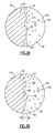
Figure 3A shows a fatigued surface of theFigure 2 serviceable component compared to a former surface. -
Figure 3B shows the fatigued portion of theFigure 2 serviceable component compared to a maintained surface. -
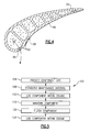
Figure 4 shows a section view at line 4-4 of theFigure 2 serviceable component. -
Figure 1 schematically illustrates an examplegas turbine engine 10 including (in serial flow communication) afan section 14, a low-pressure compressor 18, a high-pressure compressor 22, acombustor 26, a high-pressure turbine 30, and a low-pressure turbine 34. Thegas turbine engine 10 is circumferentially disposed about an engine centerline X. During operation, air is pulled into thegas turbine engine 10 by thefan section 14, pressurized by thecompressors combustor 26. Theturbines combustor 26. - In a two-spool design, the high-
pressure turbine 30 utilizes the extracted energy from the hot combustion gases to power the high-pressure compressor 22 through ahigh speed shaft 38. The low-pressure turbine 34 utilizes the extracted energy from the hot combustion gases to power the low-pressure compressor 18 and thefan section 14 through alow speed shaft 42. The examples described in this disclosure are not limited to the two-spool architecture described and may be used in other architectures, such as a single-spool axial design, a three-spool axial design, and still other architectures. That is, there are various types of engines that could benefit from the examples disclosed herein, which are not limited to the design shown. - Referring to
Figures 2-4 with continuing reference toFigure 1 , an exampleserviceable component 50 of theengine 10 includes a plurality ofinternal walls 54 establishingcooling channels 58 that are configured to communicate a cooling flow of air through theserviceable component 50 when theengine 10 is operating. The flow of air moves from thecooling channels 58 through a plurality offilm cooling holes 62 established in anouter shell 66 of theserviceable component 50. - In this example, the
serviceable component 50 is a used blade of theengine 10. Other examples of theserviceable component 50 include used vanes, used disks, etc. Theserviceable component 50 is generally described as any component of theengine 10 that is susceptible to fatigue crack initiation due to surface roughness. - As known, using the
serviceable component 50 within theengine 10 wears theserviceable component 50, which results in afatigued surface 70. Adashed line 74 represents a former surface of theserviceable component 50, which, in this example, represents the surface of theserviceable component 50 when theserviceable component 50 was manufactured and prior to using theserviceable component 50 within theengine 10. Using theserviceable component 50 thus wears the former surface to thefatigued surface 70. In some examples, the more theserviceable component 50 is used, the rougher thefatigued surface 70 becomes. - The
fatigued surface 70 being rougher than the former surface means, in this example, that there is more variation in thefatigued surface 70 than in the former surface. For example, thefatigued surface 70 includes anextrusion 78 corresponding to a portion of thefatigued surface 70 that extends past the former surface, and anintrusion 82 corresponding to a portion of thefatigued surface 70 extending away from the former surface. Relative differences between a position of theextrusion 78 and a position of theintrusion 82 represent variation in thefatigued surface 70. As known, the roughness of thefatigued surface 70 can undesirably facilitate crack formation in theserviceable component 50. - In some examples, the roughness of the
fatigued surface 70 is microscopic. The roughness in the figures has been exaggerated in this example for clarity. Thefatigued surface 70 is also an internal surface of theserviceable component 50 in this example. In another example, thefatigued surface 70 is an external surface of theserviceable component 50 or a surface of another component of theengine 10. Compressor disks are an example of theserviceable component 50 having external surfaces that are fatigued. - During maintenance of the
serviceable component 50, material beyond areference line 86 is removed from theserviceable component 50 to establish a maintained surface that is smoother than thefatigued surface 70. The maintained surface, which is aligned with thereference line 86, is smoother than thefatigued surface 70. Accordingly, the maintained surface discourages crack nucleation more than thefatigued surface 70. Discouraging crack formation extends the useful life of theserviceable component 50. - The maintained surface being smoother than the
fatigued surface 70 means generally that there is less variation in the maintained surface than in thefatigued surface 70. In this example, both theextrusions 78 and theintrusions 82 are removed from theserviceable component 50 to establish the maintained surface. In another example, the size of theextrusions 78 and theintrusions 82 is reduced to establish the maintained surface. A reduction in relative differences between a position of theextrusion 78 and a position of theintrusion 82 smoothes thefatigued surface 70. - In this example, a
solution 90 including afluid 94 that entrains an abrasive 98 is communicated through thecooling channel 58 of theserviceable component 50 to smooth thefatigued surface 70. The abrasive 98 removes portions of theserviceable component 50 as thesolution 90 passes over theserviceable component 50. The fluid 94 has a paste-like consistency in one example. The fluid 94 then entrains the removed portions of theserviceable component 50 away from theserviceable component 50. - The
example solution 90 is a liquid honing solution. Some examples of thesolution 90 that are suitable for communicating through theserviceable component 50 separate from other portions of theengine 10 utilize an aluminum oxide (or similar light abrasive) and have the paste-like consistency. ExtrudeHoneTM is one example of such asolution 90. - Examples of the
solution 90 that are suitable for communicating through theserviceable component 50 within theengine 10 also utilize aluminum oxide, but as a smaller percentage (e.g., 5%) of thesolution 90. The other portion of thesolution 90 is typically water but may include other cleaning agents in some examples. - In one example, the distance d between the
extrusion 78 and the maintained surface is between 1 and 5 microns. Thus removing no more than 5 microns of material from some areas of theserviceable component 50 can provide the maintained surface. In addition to removing portions of theserviceable component 50, the example abrasive 98 also removes byproducts of combustion, such as oxidation resulting from operation of theengine 10. - In one example, communicating the
solution 90 through theinternal channels 58 involves introducing thesolution 90 to theengine 10 while theengine 10 is operating. For example, thesolution 90 can be sprayed at theengine 10 while theengine 10 is operating. In such an example, air and thesolution 90 are both pulled into theengine 10. Thesolution 90 then circulates through theengine 10, including theinternal channels 58, to smooth thefatigued surface 70 of theserviceable component 50 or other components, such as airfoil ribs, cooling holes, etc. Another rinsing solution (not shown) is circulated through theengine 10 in some examples to remove any remaining material associated with thesolution 90 moving through theengine 10. In such an example, thesolution 90 also refinishes exterior portions of theengine 10 as thesolution 90 is sprayed at theengine 10 and moves against the exterior portions. - The figures show the
serviceable component 50 separate from other portions of theengine 10 for clarity. However, theexample solution 90 moves through the cooling channels of theserviceable component 50 while theserviceable component 50 is installed within theengine 10 in this example. Other examples move solution through theserviceable component 50 while theserviceable component 50 is uninstalled or while theserviceable component 50 is partially installed. - Referring to
Figure 5 , the abrasive 98 within thesolution 90 moving through the film cooling holes 62 removes material from theserviceable component 50 inareas 99 to soften or polish areas of theserviceable component 50 near the exits of the film cooling holes 62. The polishing reduces the edge curvature radius near the exits, which reduces the material stress in theserviceable component 50 near the film cooling holes 62. In one example, smoothing theserviceable component 50 inareas 99 by 5 microns increases the period of expected use before detectable cracks initiate in theserviceable component 50 by 30% - 50%. - A flow chart of an
example maintenance method 100 is shown in Figure 6. Atstep 104, the predicted life of a serviceable component is determined. In this example, the predicted life represents the number of hours of use that would cause cracks to form in the serviceable component if the surfaces of the serviceable component were not maintained. Other examples include a period of time, etc. - At
step 108, a maintenance interval for the serviceable component is established. In some examples, the maintenance interval is between 40% and 70% of the predicted life of the serviceable component. In a more specific example, the serviceable component is a turbine blade and the maintenance interval ranges between 50% and 60% of the predicted life of the turbine blade. At 112, the serviceable component is used within the engine. A surface of the serviceable component is maintained atstep 116 after the serviceable component use corresponds to the maintenance interval established instep 108. - In this example, surface smoothing techniques utilizing an abrasive entrained within a fluid are utilized to maintain the serviceable component. Step 116 may or may not include removing the serviceable component from an installed position within the engine. In some examples, the serviceable component, such as a blade, remains installed within the engine as the fluid moves across the surface of the serviceable component. In other examples, the serviceable component is removed or partially removed from the engine and placed on a stand. The abrasive entrained within the fluid then moves through external surfaces and surfaces establishing internal passages of the serviceable component while the serviceable component is secured relative to the stand.
- At
step 120, fluid moves across the serviceable component to flush remaining solution or residue from the engine. In the examples where the serviceable component is removed or partially removed from the engine,step 120 takes place while the serviceable component is on the stand. Thestep 120 of flushing or rinsing limits damage to seals and bearings within the engine due to residual material from thestep 116. - The serviceable component is then used again within the engine at
step 124, which, if the serviceable component was removed from the engine for service, requires removing the serviceable component from the stand and reinstalling the serviceable component within the engine. - Features of the disclosed embodiment include maintaining serviceable components to extend their useable life by smoothing surfaces of the serviceable components to inhibit crack formation.
- Although a preferred embodiment has been disclosed, a worker of ordinary skill in this art would recognize that certain modifications would come within the scope of this invention. For that reason, the following claims should be studied to determine the true scope and content of this invention.
Claims (15)
- A method of maintaining a serviceable component (50) of a gas turbine engine (10), comprising:selecting a used component (50);moving a fluid (94) that entrains an abrasive material (98) against a surface (70) of the used component (50); andremoving material from the used component (50) using the abrasive (98).
- The method of claim 1, wherein the used component (50) is attached to the gas turbine engine (10) in an installed position.
- A method of maintaining a serviceable component (50) of a gas turbine engine (10), comprising:moving a fluid (94) entraining an abrasive material (98) against a surface (70) of a used component (50) when the used component is installed within a gas turbine engine (10); andremoving material from the used component (50) using the abrasive material (98).
- The method of claim 2 or 3, including circulating the fluid (94) within the gas turbine engine (10) while the gas turbine engine is operating to move the abrasive (98).
- The method of claim 4, including spraying the fluid (94) at the gas turbine engine (10).
- The method of any preceding claim, wherein the step of removing smoothes a surface of the used component (50).
- The method of any preceding claim, wherein the used component (50) is automatically selected based on use of the used component (50).
- The method of any preceding claim, including removing byproducts of combustion using the fluid (94).
- The method of any preceding claim, wherein the surface (70) comprises an interior surface (70) of the component (50).
- The method of any preceding claim, wherein a material thickness of between about 1 and 5 microns are removed from the used component (50) during the removing step.
- The method of any preceding claim, wherein about 50% of a minimum useful life of the component (50) has been used.
- A serviceable component of a gas turbine engine, comprising:a used component (50) of a gas turbine engine having a surface (70) at least partially formed by an abrasive material (98) carried by a fluid (94), the surface (70) smoother than a fatigued surface of the component that is at least partially formed by operating the gas turbine engine.
- The method or component of any preceding claim, wherein the used component (50) comprises a used blade (50).
- The method or component of claim 13, wherein the surface (70) establishes at least a portion of a cooling channel (58) within the used blade (50).
- The method or component of any preceding claim, wherein a liquid honing solution (90) includes the abrasive (98) and the fluid (94).
Applications Claiming Priority (1)
| Application Number | Priority Date | Filing Date | Title |
|---|---|---|---|
| US12/398,979 US8776370B2 (en) | 2009-03-05 | 2009-03-05 | Method of maintaining gas turbine engine components |
Publications (3)
| Publication Number | Publication Date |
|---|---|
| EP2226467A2 true EP2226467A2 (en) | 2010-09-08 |
| EP2226467A3 EP2226467A3 (en) | 2013-10-16 |
| EP2226467B1 EP2226467B1 (en) | 2018-09-05 |
Family
ID=41811406
Family Applications (1)
| Application Number | Title | Priority Date | Filing Date |
|---|---|---|---|
| EP10250111.1A Not-in-force EP2226467B1 (en) | 2009-03-05 | 2010-01-22 | Method of maintaining gas turbine engine components |
Country Status (2)
| Country | Link |
|---|---|
| US (1) | US8776370B2 (en) |
| EP (1) | EP2226467B1 (en) |
Cited By (2)
| Publication number | Priority date | Publication date | Assignee | Title |
|---|---|---|---|---|
| EP3189935A1 (en) * | 2016-01-05 | 2017-07-12 | General Electric Company | Abrasive gel detergent for cleaning gas turbine engine components |
| CN119658574A (en) * | 2025-02-19 | 2025-03-21 | 上海理工大学 | A high-pressure turbine blade positioning and inner cavity polishing device |
Families Citing this family (4)
| Publication number | Priority date | Publication date | Assignee | Title |
|---|---|---|---|---|
| WO2015073845A1 (en) | 2013-11-15 | 2015-05-21 | United Technologies Corporation | Fluidic machining method and system |
| US10646977B2 (en) | 2016-06-17 | 2020-05-12 | United Technologies Corporation | Abrasive flow machining method |
| US11407067B2 (en) * | 2018-06-29 | 2022-08-09 | Pratt & Whitney Canada Corp. | Method for repairing a part |
| DE102022201310A1 (en) * | 2022-02-08 | 2023-08-10 | Aktiebolaget Skf | Methods for extending the life of a product and a remanufactured product |
Family Cites Families (22)
| Publication number | Priority date | Publication date | Assignee | Title |
|---|---|---|---|---|
| US3025189A (en) * | 1958-12-10 | 1962-03-13 | Purex Corp Ltd | Composition and process for removing heat scale from metal parts |
| US3216857A (en) * | 1962-05-21 | 1965-11-09 | Wyandotte Chemicals Corp | Process for removal of carbonaceous deposits |
| US3400017A (en) * | 1967-03-21 | 1968-09-03 | Chrysler Corp | Turbine engine cleaning |
| US3607398A (en) * | 1969-06-18 | 1971-09-21 | Avco Corp | Chemical stripping process |
| US4008844A (en) * | 1975-01-06 | 1977-02-22 | United Technologies Corporation | Method of repairing surface defects using metallic filler material |
| US4065322A (en) * | 1976-02-23 | 1977-12-27 | General Electric Company | Contamination removal method |
| US4439241A (en) * | 1982-03-01 | 1984-03-27 | United Technologies Corporation | Cleaning process for internal passages of superalloy airfoils |
| US5290364A (en) * | 1992-07-22 | 1994-03-01 | Grand Northern Products, Ltd. | Process for blast cleaning fixtures having internal passageways |
| US5391256A (en) * | 1993-04-05 | 1995-02-21 | General Electric Company | Hollow airfoil cavity surface texture enhancement |
| US5341602A (en) * | 1993-04-14 | 1994-08-30 | Williams International Corporation | Apparatus for improved slurry polishing |
| US5575858A (en) * | 1994-05-02 | 1996-11-19 | United Technologies Corporation | Effective cleaning method for turbine airfoils |
| WO1996015863A1 (en) * | 1994-11-22 | 1996-05-30 | United Technologies Corporation | Cleaning method for turbine airfoils by ultrasonics |
| US5702288A (en) | 1995-08-30 | 1997-12-30 | United Technologies Corporation | Method of removing excess overlay coating from within cooling holes of aluminide coated gas turbine engine components |
| GB9723762D0 (en) * | 1997-11-12 | 1998-01-07 | Rolls Royce Plc | A method of coating a component |
| EP1115906B1 (en) * | 1998-09-21 | 2003-02-05 | Siemens Aktiengesellschaft | Method for processing the interior of a hollow part |
| US6368060B1 (en) * | 2000-05-23 | 2002-04-09 | General Electric Company | Shaped cooling hole for an airfoil |
| US7144302B2 (en) * | 2000-12-27 | 2006-12-05 | Siemens Aktiengesellschaft | Method for smoothing the surface of a gas turbine blade |
| US6663919B2 (en) * | 2002-03-01 | 2003-12-16 | General Electric Company | Process of removing a coating deposit from a through-hole in a component and component processed thereby |
| US6805140B2 (en) * | 2002-10-15 | 2004-10-19 | United Technologies Corporation | Apparatus and method for cleaning airfoil internal cavities |
| US7185662B2 (en) * | 2003-11-14 | 2007-03-06 | United Technologies Corporation | Methods of preparing, cleaning and repairing article and article repaired |
| US7509735B2 (en) * | 2004-04-22 | 2009-03-31 | Siemens Energy, Inc. | In-frame repairing system of gas turbine components |
| AU2004319041B2 (en) * | 2004-04-28 | 2008-11-06 | Kabushiki Kaisha Toshiba | Device and method for polishing large part |
-
2009
- 2009-03-05 US US12/398,979 patent/US8776370B2/en active Active
-
2010
- 2010-01-22 EP EP10250111.1A patent/EP2226467B1/en not_active Not-in-force
Non-Patent Citations (1)
| Title |
|---|
| None |
Cited By (3)
| Publication number | Priority date | Publication date | Assignee | Title |
|---|---|---|---|---|
| EP3189935A1 (en) * | 2016-01-05 | 2017-07-12 | General Electric Company | Abrasive gel detergent for cleaning gas turbine engine components |
| US10428683B2 (en) | 2016-01-05 | 2019-10-01 | General Electric Company | Abrasive gel detergent for cleaning gas turbine engine components |
| CN119658574A (en) * | 2025-02-19 | 2025-03-21 | 上海理工大学 | A high-pressure turbine blade positioning and inner cavity polishing device |
Also Published As
| Publication number | Publication date |
|---|---|
| US8776370B2 (en) | 2014-07-15 |
| EP2226467B1 (en) | 2018-09-05 |
| US20100223788A1 (en) | 2010-09-09 |
| EP2226467A3 (en) | 2013-10-16 |
Similar Documents
| Publication | Publication Date | Title |
|---|---|---|
| EP2226467B1 (en) | Method of maintaining gas turbine engine components | |
| EP3208432B1 (en) | System and method for repairing an abradable material | |
| US9085053B2 (en) | In-situ turbine blade tip repair | |
| EP3213827B1 (en) | Dry detergent and method for cleaning gas turbine engine components | |
| US8807955B2 (en) | Abrasive airfoil tip | |
| EP2236749B1 (en) | Turbine blade and corresponding method of cooling | |
| US7980813B2 (en) | Fan outlet guide vane shroud insert repair | |
| US9752593B2 (en) | Method of manufacturing a gas turbine engine having a fan track liner with an abradable layer | |
| EP3222751B1 (en) | Gas turbine in situ inflatable bladders for on-wing repair | |
| US9102014B2 (en) | Method of servicing an airfoil assembly for use in a gas turbine engine | |
| EP3315941B1 (en) | Method of inspecting component abrasive surface with marking media | |
| EP3238838B1 (en) | Acoustic cleaning of gas turbine engine components | |
| US10738620B2 (en) | Cooling arrangement for engine components | |
| EP3434865A1 (en) | Method to strip and recoat erosion coatings applied to fan blades and structural guide vanes | |
| US10722912B2 (en) | Lock assembly for grit boot mask tool | |
| US20050139235A1 (en) | Methods of preparing, cleaning and repairing article and article repaired | |
| NL2002340C2 (en) | Method for repairing a cooled turbine nozzle segment. | |
| JP2004044497A (en) | Method for maintaining turbine moving blade | |
| EP1704933B1 (en) | Methods of preparing, cleaning and repairing an article | |
| US20160230557A1 (en) | Hot section repair of metallic coatings |
Legal Events
| Date | Code | Title | Description |
|---|---|---|---|
| PUAI | Public reference made under article 153(3) epc to a published international application that has entered the european phase |
Free format text: ORIGINAL CODE: 0009012 |
|
| AK | Designated contracting states |
Kind code of ref document: A2 Designated state(s): AT BE BG CH CY CZ DE DK EE ES FI FR GB GR HR HU IE IS IT LI LT LU LV MC MK MT NL NO PL PT RO SE SI SK SM TR |
|
| AX | Request for extension of the european patent |
Extension state: AL BA RS |
|
| PUAL | Search report despatched |
Free format text: ORIGINAL CODE: 0009013 |
|
| AK | Designated contracting states |
Kind code of ref document: A3 Designated state(s): AT BE BG CH CY CZ DE DK EE ES FI FR GB GR HR HU IE IS IT LI LT LU LV MC MK MT NL NO PL PT RO SE SI SK SM TR |
|
| AX | Request for extension of the european patent |
Extension state: AL BA RS |
|
| RIC1 | Information provided on ipc code assigned before grant |
Ipc: F01D 25/00 20060101ALI20130906BHEP Ipc: F01D 5/00 20060101AFI20130906BHEP Ipc: B24C 11/00 20060101ALI20130906BHEP |
|
| 17P | Request for examination filed |
Effective date: 20140321 |
|
| RBV | Designated contracting states (corrected) |
Designated state(s): AT BE BG CH CY CZ DE DK EE ES FI FR GB GR HR HU IE IS IT LI LT LU LV MC MK MT NL NO PL PT RO SE SI SK SM TR |
|
| RAP1 | Party data changed (applicant data changed or rights of an application transferred) |
Owner name: UNITED TECHNOLOGIES CORPORATION |
|
| GRAP | Despatch of communication of intention to grant a patent |
Free format text: ORIGINAL CODE: EPIDOSNIGR1 |
|
| STAA | Information on the status of an ep patent application or granted ep patent |
Free format text: STATUS: GRANT OF PATENT IS INTENDED |
|
| INTG | Intention to grant announced |
Effective date: 20180328 |
|
| GRAS | Grant fee paid |
Free format text: ORIGINAL CODE: EPIDOSNIGR3 |
|
| GRAA | (expected) grant |
Free format text: ORIGINAL CODE: 0009210 |
|
| STAA | Information on the status of an ep patent application or granted ep patent |
Free format text: STATUS: THE PATENT HAS BEEN GRANTED |
|
| AK | Designated contracting states |
Kind code of ref document: B1 Designated state(s): AT BE BG CH CY CZ DE DK EE ES FI FR GB GR HR HU IE IS IT LI LT LU LV MC MK MT NL NO PL PT RO SE SI SK SM TR |
|
| REG | Reference to a national code |
Ref country code: GB Ref legal event code: FG4D |
|
| REG | Reference to a national code |
Ref country code: CH Ref legal event code: EP |
|
| REG | Reference to a national code |
Ref country code: AT Ref legal event code: REF Ref document number: 1038027 Country of ref document: AT Kind code of ref document: T Effective date: 20180915 |
|
| REG | Reference to a national code |
Ref country code: IE Ref legal event code: FG4D |
|
| REG | Reference to a national code |
Ref country code: DE Ref legal event code: R096 Ref document number: 602010053280 Country of ref document: DE |
|
| REG | Reference to a national code |
Ref country code: NL Ref legal event code: MP Effective date: 20180905 |
|
| REG | Reference to a national code |
Ref country code: LT Ref legal event code: MG4D |
|
| PG25 | Lapsed in a contracting state [announced via postgrant information from national office to epo] |
Ref country code: BG Free format text: LAPSE BECAUSE OF FAILURE TO SUBMIT A TRANSLATION OF THE DESCRIPTION OR TO PAY THE FEE WITHIN THE PRESCRIBED TIME-LIMIT Effective date: 20181205 Ref country code: GR Free format text: LAPSE BECAUSE OF FAILURE TO SUBMIT A TRANSLATION OF THE DESCRIPTION OR TO PAY THE FEE WITHIN THE PRESCRIBED TIME-LIMIT Effective date: 20181206 Ref country code: NO Free format text: LAPSE BECAUSE OF FAILURE TO SUBMIT A TRANSLATION OF THE DESCRIPTION OR TO PAY THE FEE WITHIN THE PRESCRIBED TIME-LIMIT Effective date: 20181205 Ref country code: LT Free format text: LAPSE BECAUSE OF FAILURE TO SUBMIT A TRANSLATION OF THE DESCRIPTION OR TO PAY THE FEE WITHIN THE PRESCRIBED TIME-LIMIT Effective date: 20180905 Ref country code: FI Free format text: LAPSE BECAUSE OF FAILURE TO SUBMIT A TRANSLATION OF THE DESCRIPTION OR TO PAY THE FEE WITHIN THE PRESCRIBED TIME-LIMIT Effective date: 20180905 Ref country code: SE Free format text: LAPSE BECAUSE OF FAILURE TO SUBMIT A TRANSLATION OF THE DESCRIPTION OR TO PAY THE FEE WITHIN THE PRESCRIBED TIME-LIMIT Effective date: 20180905 |
|
| REG | Reference to a national code |
Ref country code: AT Ref legal event code: MK05 Ref document number: 1038027 Country of ref document: AT Kind code of ref document: T Effective date: 20180905 |
|
| PG25 | Lapsed in a contracting state [announced via postgrant information from national office to epo] |
Ref country code: LV Free format text: LAPSE BECAUSE OF FAILURE TO SUBMIT A TRANSLATION OF THE DESCRIPTION OR TO PAY THE FEE WITHIN THE PRESCRIBED TIME-LIMIT Effective date: 20180905 Ref country code: HR Free format text: LAPSE BECAUSE OF FAILURE TO SUBMIT A TRANSLATION OF THE DESCRIPTION OR TO PAY THE FEE WITHIN THE PRESCRIBED TIME-LIMIT Effective date: 20180905 Ref country code: ES Free format text: LAPSE BECAUSE OF FAILURE TO SUBMIT A TRANSLATION OF THE DESCRIPTION OR TO PAY THE FEE WITHIN THE PRESCRIBED TIME-LIMIT Effective date: 20180905 |
|
| PG25 | Lapsed in a contracting state [announced via postgrant information from national office to epo] |
Ref country code: PL Free format text: LAPSE BECAUSE OF FAILURE TO SUBMIT A TRANSLATION OF THE DESCRIPTION OR TO PAY THE FEE WITHIN THE PRESCRIBED TIME-LIMIT Effective date: 20180905 Ref country code: NL Free format text: LAPSE BECAUSE OF FAILURE TO SUBMIT A TRANSLATION OF THE DESCRIPTION OR TO PAY THE FEE WITHIN THE PRESCRIBED TIME-LIMIT Effective date: 20180905 Ref country code: IS Free format text: LAPSE BECAUSE OF FAILURE TO SUBMIT A TRANSLATION OF THE DESCRIPTION OR TO PAY THE FEE WITHIN THE PRESCRIBED TIME-LIMIT Effective date: 20190105 Ref country code: RO Free format text: LAPSE BECAUSE OF FAILURE TO SUBMIT A TRANSLATION OF THE DESCRIPTION OR TO PAY THE FEE WITHIN THE PRESCRIBED TIME-LIMIT Effective date: 20180905 Ref country code: CZ Free format text: LAPSE BECAUSE OF FAILURE TO SUBMIT A TRANSLATION OF THE DESCRIPTION OR TO PAY THE FEE WITHIN THE PRESCRIBED TIME-LIMIT Effective date: 20180905 Ref country code: IT Free format text: LAPSE BECAUSE OF FAILURE TO SUBMIT A TRANSLATION OF THE DESCRIPTION OR TO PAY THE FEE WITHIN THE PRESCRIBED TIME-LIMIT Effective date: 20180905 Ref country code: AT Free format text: LAPSE BECAUSE OF FAILURE TO SUBMIT A TRANSLATION OF THE DESCRIPTION OR TO PAY THE FEE WITHIN THE PRESCRIBED TIME-LIMIT Effective date: 20180905 Ref country code: EE Free format text: LAPSE BECAUSE OF FAILURE TO SUBMIT A TRANSLATION OF THE DESCRIPTION OR TO PAY THE FEE WITHIN THE PRESCRIBED TIME-LIMIT Effective date: 20180905 |
|
| PG25 | Lapsed in a contracting state [announced via postgrant information from national office to epo] |
Ref country code: SK Free format text: LAPSE BECAUSE OF FAILURE TO SUBMIT A TRANSLATION OF THE DESCRIPTION OR TO PAY THE FEE WITHIN THE PRESCRIBED TIME-LIMIT Effective date: 20180905 Ref country code: SM Free format text: LAPSE BECAUSE OF FAILURE TO SUBMIT A TRANSLATION OF THE DESCRIPTION OR TO PAY THE FEE WITHIN THE PRESCRIBED TIME-LIMIT Effective date: 20180905 Ref country code: PT Free format text: LAPSE BECAUSE OF FAILURE TO SUBMIT A TRANSLATION OF THE DESCRIPTION OR TO PAY THE FEE WITHIN THE PRESCRIBED TIME-LIMIT Effective date: 20190105 |
|
| REG | Reference to a national code |
Ref country code: DE Ref legal event code: R097 Ref document number: 602010053280 Country of ref document: DE |
|
| PLBE | No opposition filed within time limit |
Free format text: ORIGINAL CODE: 0009261 |
|
| STAA | Information on the status of an ep patent application or granted ep patent |
Free format text: STATUS: NO OPPOSITION FILED WITHIN TIME LIMIT |
|
| PG25 | Lapsed in a contracting state [announced via postgrant information from national office to epo] |
Ref country code: DK Free format text: LAPSE BECAUSE OF FAILURE TO SUBMIT A TRANSLATION OF THE DESCRIPTION OR TO PAY THE FEE WITHIN THE PRESCRIBED TIME-LIMIT Effective date: 20180905 |
|
| 26N | No opposition filed |
Effective date: 20190606 |
|
| PG25 | Lapsed in a contracting state [announced via postgrant information from national office to epo] |
Ref country code: SI Free format text: LAPSE BECAUSE OF FAILURE TO SUBMIT A TRANSLATION OF THE DESCRIPTION OR TO PAY THE FEE WITHIN THE PRESCRIBED TIME-LIMIT Effective date: 20180905 Ref country code: MC Free format text: LAPSE BECAUSE OF FAILURE TO SUBMIT A TRANSLATION OF THE DESCRIPTION OR TO PAY THE FEE WITHIN THE PRESCRIBED TIME-LIMIT Effective date: 20180905 |
|
| REG | Reference to a national code |
Ref country code: CH Ref legal event code: PL |
|
| PG25 | Lapsed in a contracting state [announced via postgrant information from national office to epo] |
Ref country code: LU Free format text: LAPSE BECAUSE OF NON-PAYMENT OF DUE FEES Effective date: 20190122 |
|
| REG | Reference to a national code |
Ref country code: BE Ref legal event code: MM Effective date: 20190131 |
|
| REG | Reference to a national code |
Ref country code: IE Ref legal event code: MM4A |
|
| PG25 | Lapsed in a contracting state [announced via postgrant information from national office to epo] |
Ref country code: FR Free format text: LAPSE BECAUSE OF NON-PAYMENT OF DUE FEES Effective date: 20190131 |
|
| PG25 | Lapsed in a contracting state [announced via postgrant information from national office to epo] |
Ref country code: BE Free format text: LAPSE BECAUSE OF NON-PAYMENT OF DUE FEES Effective date: 20190131 |
|
| PG25 | Lapsed in a contracting state [announced via postgrant information from national office to epo] |
Ref country code: LI Free format text: LAPSE BECAUSE OF NON-PAYMENT OF DUE FEES Effective date: 20190131 Ref country code: CH Free format text: LAPSE BECAUSE OF NON-PAYMENT OF DUE FEES Effective date: 20190131 |
|
| PG25 | Lapsed in a contracting state [announced via postgrant information from national office to epo] |
Ref country code: IE Free format text: LAPSE BECAUSE OF NON-PAYMENT OF DUE FEES Effective date: 20190122 |
|
| PG25 | Lapsed in a contracting state [announced via postgrant information from national office to epo] |
Ref country code: TR Free format text: LAPSE BECAUSE OF FAILURE TO SUBMIT A TRANSLATION OF THE DESCRIPTION OR TO PAY THE FEE WITHIN THE PRESCRIBED TIME-LIMIT Effective date: 20180905 |
|
| PG25 | Lapsed in a contracting state [announced via postgrant information from national office to epo] |
Ref country code: MT Free format text: LAPSE BECAUSE OF NON-PAYMENT OF DUE FEES Effective date: 20190122 |
|
| PG25 | Lapsed in a contracting state [announced via postgrant information from national office to epo] |
Ref country code: CY Free format text: LAPSE BECAUSE OF FAILURE TO SUBMIT A TRANSLATION OF THE DESCRIPTION OR TO PAY THE FEE WITHIN THE PRESCRIBED TIME-LIMIT Effective date: 20180905 |
|
| PG25 | Lapsed in a contracting state [announced via postgrant information from national office to epo] |
Ref country code: HU Free format text: LAPSE BECAUSE OF FAILURE TO SUBMIT A TRANSLATION OF THE DESCRIPTION OR TO PAY THE FEE WITHIN THE PRESCRIBED TIME-LIMIT; INVALID AB INITIO Effective date: 20100122 |
|
| PGFP | Annual fee paid to national office [announced via postgrant information from national office to epo] |
Ref country code: GB Payment date: 20211216 Year of fee payment: 13 |
|
| PGFP | Annual fee paid to national office [announced via postgrant information from national office to epo] |
Ref country code: DE Payment date: 20211215 Year of fee payment: 13 |
|
| PG25 | Lapsed in a contracting state [announced via postgrant information from national office to epo] |
Ref country code: MK Free format text: LAPSE BECAUSE OF FAILURE TO SUBMIT A TRANSLATION OF THE DESCRIPTION OR TO PAY THE FEE WITHIN THE PRESCRIBED TIME-LIMIT Effective date: 20180905 |
|
| REG | Reference to a national code |
Ref country code: DE Ref legal event code: R081 Ref document number: 602010053280 Country of ref document: DE Owner name: RAYTHEON TECHNOLOGIES CORPORATION (N.D.GES.D.S, US Free format text: FORMER OWNER: UNITED TECHNOLOGIES CORPORATION, FARMINGTON, CONN., US |
|
| REG | Reference to a national code |
Ref country code: DE Ref legal event code: R119 Ref document number: 602010053280 Country of ref document: DE |
|
| GBPC | Gb: european patent ceased through non-payment of renewal fee |
Effective date: 20230122 |
|
| PG25 | Lapsed in a contracting state [announced via postgrant information from national office to epo] |
Ref country code: GB Free format text: LAPSE BECAUSE OF NON-PAYMENT OF DUE FEES Effective date: 20230122 Ref country code: DE Free format text: LAPSE BECAUSE OF NON-PAYMENT OF DUE FEES Effective date: 20230801 |