EP2226409A2 - Erosion and corrosion resistant turbine compressor airfoil and method of making the same - Google Patents
Erosion and corrosion resistant turbine compressor airfoil and method of making the same Download PDFInfo
- Publication number
- EP2226409A2 EP2226409A2 EP10155190A EP10155190A EP2226409A2 EP 2226409 A2 EP2226409 A2 EP 2226409A2 EP 10155190 A EP10155190 A EP 10155190A EP 10155190 A EP10155190 A EP 10155190A EP 2226409 A2 EP2226409 A2 EP 2226409A2
- Authority
- EP
- European Patent Office
- Prior art keywords
- erosion
- airfoil
- coating
- turbine compressor
- resistant coating
- Prior art date
- Legal status (The legal status is an assumption and is not a legal conclusion. Google has not performed a legal analysis and makes no representation as to the accuracy of the status listed.)
- Withdrawn
Links
- 230000003628 erosive effect Effects 0.000 title claims abstract description 131
- 230000007797 corrosion Effects 0.000 title claims abstract description 42
- 238000005260 corrosion Methods 0.000 title claims abstract description 42
- 238000004519 manufacturing process Methods 0.000 title claims description 5
- 238000000576 coating method Methods 0.000 claims abstract description 217
- 239000011248 coating agent Substances 0.000 claims abstract description 203
- 229910045601 alloy Inorganic materials 0.000 claims abstract description 49
- 239000000956 alloy Substances 0.000 claims abstract description 49
- 239000000919 ceramic Substances 0.000 claims abstract description 37
- 239000002245 particle Substances 0.000 claims abstract description 34
- 239000011159 matrix material Substances 0.000 claims abstract description 18
- 229910052782 aluminium Inorganic materials 0.000 claims abstract description 17
- 239000011230 binding agent Substances 0.000 claims abstract description 17
- 229910052804 chromium Inorganic materials 0.000 claims abstract description 16
- 229920000642 polymer Polymers 0.000 claims abstract description 13
- 239000002131 composite material Substances 0.000 claims abstract description 11
- 229910052725 zinc Inorganic materials 0.000 claims abstract description 11
- 229910021364 Al-Si alloy Inorganic materials 0.000 claims abstract description 9
- 229910003310 Ni-Al Inorganic materials 0.000 claims abstract description 9
- 239000010410 layer Substances 0.000 claims description 83
- ATJFFYVFTNAWJD-UHFFFAOYSA-N Tin Chemical compound [Sn] ATJFFYVFTNAWJD-UHFFFAOYSA-N 0.000 claims description 24
- 229910052751 metal Inorganic materials 0.000 claims description 21
- 239000002184 metal Substances 0.000 claims description 21
- 239000011195 cermet Substances 0.000 claims description 17
- 229910001220 stainless steel Inorganic materials 0.000 claims description 13
- 239000002356 single layer Substances 0.000 claims description 10
- 239000010935 stainless steel Substances 0.000 claims description 10
- 229910000601 superalloy Inorganic materials 0.000 claims description 8
- OKTJSMMVPCPJKN-UHFFFAOYSA-N Carbon Chemical compound [C] OKTJSMMVPCPJKN-UHFFFAOYSA-N 0.000 claims description 6
- 229910000684 Cobalt-chrome Inorganic materials 0.000 claims description 6
- 229910052799 carbon Inorganic materials 0.000 claims description 6
- 239000010952 cobalt-chrome Substances 0.000 claims description 6
- 229910052742 iron Inorganic materials 0.000 claims description 5
- GWEVSGVZZGPLCZ-UHFFFAOYSA-N Titan oxide Chemical compound O=[Ti]=O GWEVSGVZZGPLCZ-UHFFFAOYSA-N 0.000 claims description 4
- MCMNRKCIXSYSNV-UHFFFAOYSA-N Zirconium dioxide Chemical compound O=[Zr]=O MCMNRKCIXSYSNV-UHFFFAOYSA-N 0.000 claims description 4
- QDOXWKRWXJOMAK-UHFFFAOYSA-N dichromium trioxide Chemical compound O=[Cr]O[Cr]=O QDOXWKRWXJOMAK-UHFFFAOYSA-N 0.000 claims description 4
- 229910052759 nickel Inorganic materials 0.000 claims description 4
- 229910003470 tongbaite Inorganic materials 0.000 claims description 4
- 229910003460 diamond Inorganic materials 0.000 claims description 3
- 239000010432 diamond Substances 0.000 claims description 3
- 150000004767 nitrides Chemical class 0.000 claims description 3
- QYEXBYZXHDUPRC-UHFFFAOYSA-N B#[Ti]#B Chemical compound B#[Ti]#B QYEXBYZXHDUPRC-UHFFFAOYSA-N 0.000 claims description 2
- 101150013999 CRBN gene Proteins 0.000 claims description 2
- 229910052581 Si3N4 Inorganic materials 0.000 claims description 2
- 229910004160 TaO2 Inorganic materials 0.000 claims description 2
- 229910033181 TiB2 Inorganic materials 0.000 claims description 2
- 229910010060 TiBN Inorganic materials 0.000 claims description 2
- 229910009043 WC-Co Inorganic materials 0.000 claims description 2
- 229910007948 ZrB2 Inorganic materials 0.000 claims description 2
- PNEYBMLMFCGWSK-UHFFFAOYSA-N aluminium oxide Inorganic materials [O-2].[O-2].[O-2].[Al+3].[Al+3] PNEYBMLMFCGWSK-UHFFFAOYSA-N 0.000 claims description 2
- VWZIXVXBCBBRGP-UHFFFAOYSA-N boron;zirconium Chemical compound B#[Zr]#B VWZIXVXBCBBRGP-UHFFFAOYSA-N 0.000 claims description 2
- CETPSERCERDGAM-UHFFFAOYSA-N ceric oxide Chemical compound O=[Ce]=O CETPSERCERDGAM-UHFFFAOYSA-N 0.000 claims description 2
- 229910000422 cerium(IV) oxide Inorganic materials 0.000 claims description 2
- 229910052593 corundum Inorganic materials 0.000 claims description 2
- NQKXFODBPINZFK-UHFFFAOYSA-N dioxotantalum Chemical compound O=[Ta]=O NQKXFODBPINZFK-UHFFFAOYSA-N 0.000 claims description 2
- 229910044991 metal oxide Inorganic materials 0.000 claims description 2
- 150000004706 metal oxides Chemical class 0.000 claims description 2
- 101150016677 ohgt gene Proteins 0.000 claims description 2
- PBCFLUZVCVVTBY-UHFFFAOYSA-N tantalum pentoxide Inorganic materials O=[Ta](=O)O[Ta](=O)=O PBCFLUZVCVVTBY-UHFFFAOYSA-N 0.000 claims description 2
- 229910001845 yogo sapphire Inorganic materials 0.000 claims description 2
- RUDFQVOCFDJEEF-UHFFFAOYSA-N yttrium(III) oxide Inorganic materials [O-2].[O-2].[O-2].[Y+3].[Y+3] RUDFQVOCFDJEEF-UHFFFAOYSA-N 0.000 claims description 2
- 239000010936 titanium Substances 0.000 description 28
- XLYOFNOQVPJJNP-UHFFFAOYSA-N water Substances O XLYOFNOQVPJJNP-UHFFFAOYSA-N 0.000 description 25
- 239000011651 chromium Substances 0.000 description 21
- 239000000463 material Substances 0.000 description 21
- 230000035882 stress Effects 0.000 description 20
- 238000012360 testing method Methods 0.000 description 19
- 238000000034 method Methods 0.000 description 18
- 239000000203 mixture Substances 0.000 description 12
- PXHVJJICTQNCMI-UHFFFAOYSA-N nickel Substances [Ni] PXHVJJICTQNCMI-UHFFFAOYSA-N 0.000 description 12
- XEEYBQQBJWHFJM-UHFFFAOYSA-N Iron Chemical compound [Fe] XEEYBQQBJWHFJM-UHFFFAOYSA-N 0.000 description 11
- 238000004544 sputter deposition Methods 0.000 description 11
- 239000003973 paint Substances 0.000 description 9
- XAGFODPZIPBFFR-UHFFFAOYSA-N aluminium Chemical compound [Al] XAGFODPZIPBFFR-UHFFFAOYSA-N 0.000 description 8
- 239000000758 substrate Substances 0.000 description 8
- FAPWRFPIFSIZLT-UHFFFAOYSA-M Sodium chloride Chemical compound [Na+].[Cl-] FAPWRFPIFSIZLT-UHFFFAOYSA-M 0.000 description 6
- 230000008901 benefit Effects 0.000 description 6
- 238000005240 physical vapour deposition Methods 0.000 description 6
- 230000008569 process Effects 0.000 description 6
- 235000002639 sodium chloride Nutrition 0.000 description 6
- 239000013626 chemical specie Substances 0.000 description 5
- 238000000151 deposition Methods 0.000 description 5
- WMYWOWFOOVUPFY-UHFFFAOYSA-L dihydroxy(dioxo)chromium;phosphoric acid Chemical compound OP(O)(O)=O.O[Cr](O)(=O)=O WMYWOWFOOVUPFY-UHFFFAOYSA-L 0.000 description 5
- 239000002923 metal particle Substances 0.000 description 5
- 230000010287 polarization Effects 0.000 description 5
- WGLPBDUCMAPZCE-UHFFFAOYSA-N Trioxochromium Chemical compound O=[Cr](=O)=O WGLPBDUCMAPZCE-UHFFFAOYSA-N 0.000 description 4
- 229910010293 ceramic material Inorganic materials 0.000 description 4
- 229910000423 chromium oxide Inorganic materials 0.000 description 4
- 125000004122 cyclic group Chemical group 0.000 description 4
- 230000008021 deposition Effects 0.000 description 4
- TWNQGVIAIRXVLR-UHFFFAOYSA-N oxo(oxoalumanyloxy)alumane Chemical compound O=[Al]O[Al]=O TWNQGVIAIRXVLR-UHFFFAOYSA-N 0.000 description 4
- -1 Al2O3 Chemical class 0.000 description 3
- IJGRMHOSHXDMSA-UHFFFAOYSA-N Atomic nitrogen Chemical compound N#N IJGRMHOSHXDMSA-UHFFFAOYSA-N 0.000 description 3
- 239000000470 constituent Substances 0.000 description 3
- 238000001816 cooling Methods 0.000 description 3
- 239000010955 niobium Substances 0.000 description 3
- GUCVJGMIXFAOAE-UHFFFAOYSA-N niobium atom Chemical compound [Nb] GUCVJGMIXFAOAE-UHFFFAOYSA-N 0.000 description 3
- 239000000376 reactant Substances 0.000 description 3
- 239000011780 sodium chloride Substances 0.000 description 3
- 239000007921 spray Substances 0.000 description 3
- 239000000126 substance Substances 0.000 description 3
- 229910052719 titanium Inorganic materials 0.000 description 3
- VEXZGXHMUGYJMC-UHFFFAOYSA-M Chloride anion Chemical compound [Cl-] VEXZGXHMUGYJMC-UHFFFAOYSA-M 0.000 description 2
- VYZAMTAEIAYCRO-UHFFFAOYSA-N Chromium Chemical compound [Cr] VYZAMTAEIAYCRO-UHFFFAOYSA-N 0.000 description 2
- ZOKXTWBITQBERF-UHFFFAOYSA-N Molybdenum Chemical compound [Mo] ZOKXTWBITQBERF-UHFFFAOYSA-N 0.000 description 2
- RTAQQCXQSZGOHL-UHFFFAOYSA-N Titanium Chemical compound [Ti] RTAQQCXQSZGOHL-UHFFFAOYSA-N 0.000 description 2
- 238000005299 abrasion Methods 0.000 description 2
- 230000002378 acidificating effect Effects 0.000 description 2
- 230000001464 adherent effect Effects 0.000 description 2
- 238000013459 approach Methods 0.000 description 2
- 238000005422 blasting Methods 0.000 description 2
- OJIJEKBXJYRIBZ-UHFFFAOYSA-N cadmium nickel Chemical compound [Ni].[Cd] OJIJEKBXJYRIBZ-UHFFFAOYSA-N 0.000 description 2
- 238000005229 chemical vapour deposition Methods 0.000 description 2
- 229910017052 cobalt Inorganic materials 0.000 description 2
- 239000010941 cobalt Substances 0.000 description 2
- GUTLYIVDDKVIGB-UHFFFAOYSA-N cobalt atom Chemical compound [Co] GUTLYIVDDKVIGB-UHFFFAOYSA-N 0.000 description 2
- 230000007547 defect Effects 0.000 description 2
- 239000010408 film Substances 0.000 description 2
- 239000007789 gas Substances 0.000 description 2
- 239000011521 glass Substances 0.000 description 2
- 238000001659 ion-beam spectroscopy Methods 0.000 description 2
- 238000001755 magnetron sputter deposition Methods 0.000 description 2
- 150000001247 metal acetylides Chemical class 0.000 description 2
- 150000002739 metals Chemical class 0.000 description 2
- VNWKTOKETHGBQD-UHFFFAOYSA-N methane Chemical compound C VNWKTOKETHGBQD-UHFFFAOYSA-N 0.000 description 2
- 229910052750 molybdenum Inorganic materials 0.000 description 2
- 239000011733 molybdenum Substances 0.000 description 2
- 239000011224 oxide ceramic Substances 0.000 description 2
- 238000005546 reactive sputtering Methods 0.000 description 2
- 229910052715 tantalum Inorganic materials 0.000 description 2
- 238000005406 washing Methods 0.000 description 2
- ZOXJGFHDIHLPTG-UHFFFAOYSA-N Boron Chemical compound [B] ZOXJGFHDIHLPTG-UHFFFAOYSA-N 0.000 description 1
- 229910000925 Cd alloy Inorganic materials 0.000 description 1
- RYGMFSIKBFXOCR-UHFFFAOYSA-N Copper Chemical compound [Cu] RYGMFSIKBFXOCR-UHFFFAOYSA-N 0.000 description 1
- KJTLSVCANCCWHF-UHFFFAOYSA-N Ruthenium Chemical compound [Ru] KJTLSVCANCCWHF-UHFFFAOYSA-N 0.000 description 1
- VYPSYNLAJGMNEJ-UHFFFAOYSA-N Silicium dioxide Chemical compound O=[Si]=O VYPSYNLAJGMNEJ-UHFFFAOYSA-N 0.000 description 1
- 229910021607 Silver chloride Inorganic materials 0.000 description 1
- 229910000831 Steel Inorganic materials 0.000 description 1
- NINIDFKCEFEMDL-UHFFFAOYSA-N Sulfur Chemical compound [S] NINIDFKCEFEMDL-UHFFFAOYSA-N 0.000 description 1
- QCWXUUIWCKQGHC-UHFFFAOYSA-N Zirconium Chemical compound [Zr] QCWXUUIWCKQGHC-UHFFFAOYSA-N 0.000 description 1
- 230000004075 alteration Effects 0.000 description 1
- 239000010405 anode material Substances 0.000 description 1
- 230000003373 anti-fouling effect Effects 0.000 description 1
- 230000003416 augmentation Effects 0.000 description 1
- 239000011324 bead Substances 0.000 description 1
- 229910052796 boron Inorganic materials 0.000 description 1
- 230000015556 catabolic process Effects 0.000 description 1
- 230000008859 change Effects 0.000 description 1
- 238000013034 coating degradation Methods 0.000 description 1
- 238000002485 combustion reaction Methods 0.000 description 1
- 150000001875 compounds Chemical class 0.000 description 1
- 238000007596 consolidation process Methods 0.000 description 1
- 229910052802 copper Inorganic materials 0.000 description 1
- 239000010949 copper Substances 0.000 description 1
- 238000005336 cracking Methods 0.000 description 1
- 239000013078 crystal Substances 0.000 description 1
- 230000003247 decreasing effect Effects 0.000 description 1
- 238000006731 degradation reaction Methods 0.000 description 1
- 238000013461 design Methods 0.000 description 1
- 229910001873 dinitrogen Inorganic materials 0.000 description 1
- 238000007598 dipping method Methods 0.000 description 1
- 238000004090 dissolution Methods 0.000 description 1
- 238000001035 drying Methods 0.000 description 1
- 230000000694 effects Effects 0.000 description 1
- 238000003487 electrochemical reaction Methods 0.000 description 1
- 238000007772 electroless plating Methods 0.000 description 1
- 238000006056 electrooxidation reaction Methods 0.000 description 1
- 238000009713 electroplating Methods 0.000 description 1
- 230000001747 exhibiting effect Effects 0.000 description 1
- 238000002474 experimental method Methods 0.000 description 1
- 238000010285 flame spraying Methods 0.000 description 1
- 239000000446 fuel Substances 0.000 description 1
- 229910052735 hafnium Inorganic materials 0.000 description 1
- VBJZVLUMGGDVMO-UHFFFAOYSA-N hafnium atom Chemical compound [Hf] VBJZVLUMGGDVMO-UHFFFAOYSA-N 0.000 description 1
- 238000010438 heat treatment Methods 0.000 description 1
- BHEPBYXIRTUNPN-UHFFFAOYSA-N hydridophosphorus(.) (triplet) Chemical compound [PH] BHEPBYXIRTUNPN-UHFFFAOYSA-N 0.000 description 1
- 230000006872 improvement Effects 0.000 description 1
- 239000012535 impurity Substances 0.000 description 1
- 230000000977 initiatory effect Effects 0.000 description 1
- 229910052500 inorganic mineral Inorganic materials 0.000 description 1
- JEIPFZHSYJVQDO-UHFFFAOYSA-N iron(III) oxide Inorganic materials O=[Fe]O[Fe]=O JEIPFZHSYJVQDO-UHFFFAOYSA-N 0.000 description 1
- WPBNNNQJVZRUHP-UHFFFAOYSA-L manganese(2+);methyl n-[[2-(methoxycarbonylcarbamothioylamino)phenyl]carbamothioyl]carbamate;n-[2-(sulfidocarbothioylamino)ethyl]carbamodithioate Chemical compound [Mn+2].[S-]C(=S)NCCNC([S-])=S.COC(=O)NC(=S)NC1=CC=CC=C1NC(=S)NC(=O)OC WPBNNNQJVZRUHP-UHFFFAOYSA-L 0.000 description 1
- 229910000734 martensite Inorganic materials 0.000 description 1
- 230000007246 mechanism Effects 0.000 description 1
- 238000002844 melting Methods 0.000 description 1
- 230000008018 melting Effects 0.000 description 1
- 239000002905 metal composite material Substances 0.000 description 1
- 229910001092 metal group alloy Inorganic materials 0.000 description 1
- 239000011156 metal matrix composite Substances 0.000 description 1
- 239000011707 mineral Substances 0.000 description 1
- 235000010755 mineral Nutrition 0.000 description 1
- 229910052758 niobium Inorganic materials 0.000 description 1
- 229910052757 nitrogen Inorganic materials 0.000 description 1
- 238000010422 painting Methods 0.000 description 1
- 238000007750 plasma spraying Methods 0.000 description 1
- 238000007747 plating Methods 0.000 description 1
- 239000000843 powder Substances 0.000 description 1
- 230000001902 propagating effect Effects 0.000 description 1
- 230000009467 reduction Effects 0.000 description 1
- 229910052702 rhenium Inorganic materials 0.000 description 1
- WUAPFZMCVAUBPE-UHFFFAOYSA-N rhenium atom Chemical compound [Re] WUAPFZMCVAUBPE-UHFFFAOYSA-N 0.000 description 1
- 229910052707 ruthenium Inorganic materials 0.000 description 1
- 150000003839 salts Chemical class 0.000 description 1
- 239000013535 sea water Substances 0.000 description 1
- 238000005480 shot peening Methods 0.000 description 1
- 229910052710 silicon Inorganic materials 0.000 description 1
- 239000010703 silicon Substances 0.000 description 1
- 229910052814 silicon oxide Inorganic materials 0.000 description 1
- 239000007787 solid Substances 0.000 description 1
- 238000004901 spalling Methods 0.000 description 1
- 238000005507 spraying Methods 0.000 description 1
- 239000010959 steel Substances 0.000 description 1
- 238000006467 substitution reaction Methods 0.000 description 1
- 229910052717 sulfur Inorganic materials 0.000 description 1
- 239000011593 sulfur Substances 0.000 description 1
- GUVRBAGPIYLISA-UHFFFAOYSA-N tantalum atom Chemical compound [Ta] GUVRBAGPIYLISA-UHFFFAOYSA-N 0.000 description 1
- 239000013077 target material Substances 0.000 description 1
- 230000008646 thermal stress Effects 0.000 description 1
- 239000010409 thin film Substances 0.000 description 1
- 238000007736 thin film deposition technique Methods 0.000 description 1
- 238000011282 treatment Methods 0.000 description 1
- WFKWXMTUELFFGS-UHFFFAOYSA-N tungsten Chemical compound [W] WFKWXMTUELFFGS-UHFFFAOYSA-N 0.000 description 1
- 229910052721 tungsten Inorganic materials 0.000 description 1
- 239000010937 tungsten Substances 0.000 description 1
- 229910052720 vanadium Inorganic materials 0.000 description 1
- GPPXJZIENCGNKB-UHFFFAOYSA-N vanadium Chemical compound [V]#[V] GPPXJZIENCGNKB-UHFFFAOYSA-N 0.000 description 1
- 230000000007 visual effect Effects 0.000 description 1
- 229910052727 yttrium Inorganic materials 0.000 description 1
- VWQVUPCCIRVNHF-UHFFFAOYSA-N yttrium atom Chemical compound [Y] VWQVUPCCIRVNHF-UHFFFAOYSA-N 0.000 description 1
- 229910052726 zirconium Inorganic materials 0.000 description 1
Images




Classifications
-
- C—CHEMISTRY; METALLURGY
- C23—COATING METALLIC MATERIAL; COATING MATERIAL WITH METALLIC MATERIAL; CHEMICAL SURFACE TREATMENT; DIFFUSION TREATMENT OF METALLIC MATERIAL; COATING BY VACUUM EVAPORATION, BY SPUTTERING, BY ION IMPLANTATION OR BY CHEMICAL VAPOUR DEPOSITION, IN GENERAL; INHIBITING CORROSION OF METALLIC MATERIAL OR INCRUSTATION IN GENERAL
- C23C—COATING METALLIC MATERIAL; COATING MATERIAL WITH METALLIC MATERIAL; SURFACE TREATMENT OF METALLIC MATERIAL BY DIFFUSION INTO THE SURFACE, BY CHEMICAL CONVERSION OR SUBSTITUTION; COATING BY VACUUM EVAPORATION, BY SPUTTERING, BY ION IMPLANTATION OR BY CHEMICAL VAPOUR DEPOSITION, IN GENERAL
- C23C30/00—Coating with metallic material characterised only by the composition of the metallic material, i.e. not characterised by the coating process
-
- C—CHEMISTRY; METALLURGY
- C23—COATING METALLIC MATERIAL; COATING MATERIAL WITH METALLIC MATERIAL; CHEMICAL SURFACE TREATMENT; DIFFUSION TREATMENT OF METALLIC MATERIAL; COATING BY VACUUM EVAPORATION, BY SPUTTERING, BY ION IMPLANTATION OR BY CHEMICAL VAPOUR DEPOSITION, IN GENERAL; INHIBITING CORROSION OF METALLIC MATERIAL OR INCRUSTATION IN GENERAL
- C23C—COATING METALLIC MATERIAL; COATING MATERIAL WITH METALLIC MATERIAL; SURFACE TREATMENT OF METALLIC MATERIAL BY DIFFUSION INTO THE SURFACE, BY CHEMICAL CONVERSION OR SUBSTITUTION; COATING BY VACUUM EVAPORATION, BY SPUTTERING, BY ION IMPLANTATION OR BY CHEMICAL VAPOUR DEPOSITION, IN GENERAL
- C23C28/00—Coating for obtaining at least two superposed coatings either by methods not provided for in a single one of groups C23C2/00 - C23C26/00 or by combinations of methods provided for in subclasses C23C and C25C or C25D
-
- C—CHEMISTRY; METALLURGY
- C23—COATING METALLIC MATERIAL; COATING MATERIAL WITH METALLIC MATERIAL; CHEMICAL SURFACE TREATMENT; DIFFUSION TREATMENT OF METALLIC MATERIAL; COATING BY VACUUM EVAPORATION, BY SPUTTERING, BY ION IMPLANTATION OR BY CHEMICAL VAPOUR DEPOSITION, IN GENERAL; INHIBITING CORROSION OF METALLIC MATERIAL OR INCRUSTATION IN GENERAL
- C23C—COATING METALLIC MATERIAL; COATING MATERIAL WITH METALLIC MATERIAL; SURFACE TREATMENT OF METALLIC MATERIAL BY DIFFUSION INTO THE SURFACE, BY CHEMICAL CONVERSION OR SUBSTITUTION; COATING BY VACUUM EVAPORATION, BY SPUTTERING, BY ION IMPLANTATION OR BY CHEMICAL VAPOUR DEPOSITION, IN GENERAL
- C23C28/00—Coating for obtaining at least two superposed coatings either by methods not provided for in a single one of groups C23C2/00 - C23C26/00 or by combinations of methods provided for in subclasses C23C and C25C or C25D
- C23C28/04—Coating for obtaining at least two superposed coatings either by methods not provided for in a single one of groups C23C2/00 - C23C26/00 or by combinations of methods provided for in subclasses C23C and C25C or C25D only coatings of inorganic non-metallic material
- C23C28/042—Coating for obtaining at least two superposed coatings either by methods not provided for in a single one of groups C23C2/00 - C23C26/00 or by combinations of methods provided for in subclasses C23C and C25C or C25D only coatings of inorganic non-metallic material including a refractory ceramic layer, e.g. refractory metal oxides, ZrO2, rare earth oxides
-
- C—CHEMISTRY; METALLURGY
- C23—COATING METALLIC MATERIAL; COATING MATERIAL WITH METALLIC MATERIAL; CHEMICAL SURFACE TREATMENT; DIFFUSION TREATMENT OF METALLIC MATERIAL; COATING BY VACUUM EVAPORATION, BY SPUTTERING, BY ION IMPLANTATION OR BY CHEMICAL VAPOUR DEPOSITION, IN GENERAL; INHIBITING CORROSION OF METALLIC MATERIAL OR INCRUSTATION IN GENERAL
- C23C—COATING METALLIC MATERIAL; COATING MATERIAL WITH METALLIC MATERIAL; SURFACE TREATMENT OF METALLIC MATERIAL BY DIFFUSION INTO THE SURFACE, BY CHEMICAL CONVERSION OR SUBSTITUTION; COATING BY VACUUM EVAPORATION, BY SPUTTERING, BY ION IMPLANTATION OR BY CHEMICAL VAPOUR DEPOSITION, IN GENERAL
- C23C28/00—Coating for obtaining at least two superposed coatings either by methods not provided for in a single one of groups C23C2/00 - C23C26/00 or by combinations of methods provided for in subclasses C23C and C25C or C25D
- C23C28/30—Coatings combining at least one metallic layer and at least one inorganic non-metallic layer
- C23C28/32—Coatings combining at least one metallic layer and at least one inorganic non-metallic layer including at least one pure metallic layer
- C23C28/321—Coatings combining at least one metallic layer and at least one inorganic non-metallic layer including at least one pure metallic layer with at least one metal alloy layer
-
- C—CHEMISTRY; METALLURGY
- C23—COATING METALLIC MATERIAL; COATING MATERIAL WITH METALLIC MATERIAL; CHEMICAL SURFACE TREATMENT; DIFFUSION TREATMENT OF METALLIC MATERIAL; COATING BY VACUUM EVAPORATION, BY SPUTTERING, BY ION IMPLANTATION OR BY CHEMICAL VAPOUR DEPOSITION, IN GENERAL; INHIBITING CORROSION OF METALLIC MATERIAL OR INCRUSTATION IN GENERAL
- C23C—COATING METALLIC MATERIAL; COATING MATERIAL WITH METALLIC MATERIAL; SURFACE TREATMENT OF METALLIC MATERIAL BY DIFFUSION INTO THE SURFACE, BY CHEMICAL CONVERSION OR SUBSTITUTION; COATING BY VACUUM EVAPORATION, BY SPUTTERING, BY ION IMPLANTATION OR BY CHEMICAL VAPOUR DEPOSITION, IN GENERAL
- C23C28/00—Coating for obtaining at least two superposed coatings either by methods not provided for in a single one of groups C23C2/00 - C23C26/00 or by combinations of methods provided for in subclasses C23C and C25C or C25D
- C23C28/30—Coatings combining at least one metallic layer and at least one inorganic non-metallic layer
- C23C28/32—Coatings combining at least one metallic layer and at least one inorganic non-metallic layer including at least one pure metallic layer
- C23C28/322—Coatings combining at least one metallic layer and at least one inorganic non-metallic layer including at least one pure metallic layer only coatings of metal elements only
-
- C—CHEMISTRY; METALLURGY
- C23—COATING METALLIC MATERIAL; COATING MATERIAL WITH METALLIC MATERIAL; CHEMICAL SURFACE TREATMENT; DIFFUSION TREATMENT OF METALLIC MATERIAL; COATING BY VACUUM EVAPORATION, BY SPUTTERING, BY ION IMPLANTATION OR BY CHEMICAL VAPOUR DEPOSITION, IN GENERAL; INHIBITING CORROSION OF METALLIC MATERIAL OR INCRUSTATION IN GENERAL
- C23C—COATING METALLIC MATERIAL; COATING MATERIAL WITH METALLIC MATERIAL; SURFACE TREATMENT OF METALLIC MATERIAL BY DIFFUSION INTO THE SURFACE, BY CHEMICAL CONVERSION OR SUBSTITUTION; COATING BY VACUUM EVAPORATION, BY SPUTTERING, BY ION IMPLANTATION OR BY CHEMICAL VAPOUR DEPOSITION, IN GENERAL
- C23C28/00—Coating for obtaining at least two superposed coatings either by methods not provided for in a single one of groups C23C2/00 - C23C26/00 or by combinations of methods provided for in subclasses C23C and C25C or C25D
- C23C28/30—Coatings combining at least one metallic layer and at least one inorganic non-metallic layer
- C23C28/32—Coatings combining at least one metallic layer and at least one inorganic non-metallic layer including at least one pure metallic layer
- C23C28/322—Coatings combining at least one metallic layer and at least one inorganic non-metallic layer including at least one pure metallic layer only coatings of metal elements only
- C23C28/3225—Coatings combining at least one metallic layer and at least one inorganic non-metallic layer including at least one pure metallic layer only coatings of metal elements only with at least one zinc-based layer
-
- C—CHEMISTRY; METALLURGY
- C23—COATING METALLIC MATERIAL; COATING MATERIAL WITH METALLIC MATERIAL; CHEMICAL SURFACE TREATMENT; DIFFUSION TREATMENT OF METALLIC MATERIAL; COATING BY VACUUM EVAPORATION, BY SPUTTERING, BY ION IMPLANTATION OR BY CHEMICAL VAPOUR DEPOSITION, IN GENERAL; INHIBITING CORROSION OF METALLIC MATERIAL OR INCRUSTATION IN GENERAL
- C23C—COATING METALLIC MATERIAL; COATING MATERIAL WITH METALLIC MATERIAL; SURFACE TREATMENT OF METALLIC MATERIAL BY DIFFUSION INTO THE SURFACE, BY CHEMICAL CONVERSION OR SUBSTITUTION; COATING BY VACUUM EVAPORATION, BY SPUTTERING, BY ION IMPLANTATION OR BY CHEMICAL VAPOUR DEPOSITION, IN GENERAL
- C23C28/00—Coating for obtaining at least two superposed coatings either by methods not provided for in a single one of groups C23C2/00 - C23C26/00 or by combinations of methods provided for in subclasses C23C and C25C or C25D
- C23C28/30—Coatings combining at least one metallic layer and at least one inorganic non-metallic layer
- C23C28/32—Coatings combining at least one metallic layer and at least one inorganic non-metallic layer including at least one pure metallic layer
- C23C28/324—Coatings combining at least one metallic layer and at least one inorganic non-metallic layer including at least one pure metallic layer with at least one metal matrix material layer comprising a mixture of at least two metals or metal phases or a metal-matrix material with hard embedded particles, e.g. WC-Me
-
- C—CHEMISTRY; METALLURGY
- C23—COATING METALLIC MATERIAL; COATING MATERIAL WITH METALLIC MATERIAL; CHEMICAL SURFACE TREATMENT; DIFFUSION TREATMENT OF METALLIC MATERIAL; COATING BY VACUUM EVAPORATION, BY SPUTTERING, BY ION IMPLANTATION OR BY CHEMICAL VAPOUR DEPOSITION, IN GENERAL; INHIBITING CORROSION OF METALLIC MATERIAL OR INCRUSTATION IN GENERAL
- C23C—COATING METALLIC MATERIAL; COATING MATERIAL WITH METALLIC MATERIAL; SURFACE TREATMENT OF METALLIC MATERIAL BY DIFFUSION INTO THE SURFACE, BY CHEMICAL CONVERSION OR SUBSTITUTION; COATING BY VACUUM EVAPORATION, BY SPUTTERING, BY ION IMPLANTATION OR BY CHEMICAL VAPOUR DEPOSITION, IN GENERAL
- C23C28/00—Coating for obtaining at least two superposed coatings either by methods not provided for in a single one of groups C23C2/00 - C23C26/00 or by combinations of methods provided for in subclasses C23C and C25C or C25D
- C23C28/30—Coatings combining at least one metallic layer and at least one inorganic non-metallic layer
- C23C28/34—Coatings combining at least one metallic layer and at least one inorganic non-metallic layer including at least one inorganic non-metallic material layer, e.g. metal carbide, nitride, boride, silicide layer and their mixtures, enamels, phosphates and sulphates
-
- C—CHEMISTRY; METALLURGY
- C23—COATING METALLIC MATERIAL; COATING MATERIAL WITH METALLIC MATERIAL; CHEMICAL SURFACE TREATMENT; DIFFUSION TREATMENT OF METALLIC MATERIAL; COATING BY VACUUM EVAPORATION, BY SPUTTERING, BY ION IMPLANTATION OR BY CHEMICAL VAPOUR DEPOSITION, IN GENERAL; INHIBITING CORROSION OF METALLIC MATERIAL OR INCRUSTATION IN GENERAL
- C23C—COATING METALLIC MATERIAL; COATING MATERIAL WITH METALLIC MATERIAL; SURFACE TREATMENT OF METALLIC MATERIAL BY DIFFUSION INTO THE SURFACE, BY CHEMICAL CONVERSION OR SUBSTITUTION; COATING BY VACUUM EVAPORATION, BY SPUTTERING, BY ION IMPLANTATION OR BY CHEMICAL VAPOUR DEPOSITION, IN GENERAL
- C23C28/00—Coating for obtaining at least two superposed coatings either by methods not provided for in a single one of groups C23C2/00 - C23C26/00 or by combinations of methods provided for in subclasses C23C and C25C or C25D
- C23C28/30—Coatings combining at least one metallic layer and at least one inorganic non-metallic layer
- C23C28/34—Coatings combining at least one metallic layer and at least one inorganic non-metallic layer including at least one inorganic non-metallic material layer, e.g. metal carbide, nitride, boride, silicide layer and their mixtures, enamels, phosphates and sulphates
- C23C28/341—Coatings combining at least one metallic layer and at least one inorganic non-metallic layer including at least one inorganic non-metallic material layer, e.g. metal carbide, nitride, boride, silicide layer and their mixtures, enamels, phosphates and sulphates with at least one carbide layer
-
- C—CHEMISTRY; METALLURGY
- C23—COATING METALLIC MATERIAL; COATING MATERIAL WITH METALLIC MATERIAL; CHEMICAL SURFACE TREATMENT; DIFFUSION TREATMENT OF METALLIC MATERIAL; COATING BY VACUUM EVAPORATION, BY SPUTTERING, BY ION IMPLANTATION OR BY CHEMICAL VAPOUR DEPOSITION, IN GENERAL; INHIBITING CORROSION OF METALLIC MATERIAL OR INCRUSTATION IN GENERAL
- C23C—COATING METALLIC MATERIAL; COATING MATERIAL WITH METALLIC MATERIAL; SURFACE TREATMENT OF METALLIC MATERIAL BY DIFFUSION INTO THE SURFACE, BY CHEMICAL CONVERSION OR SUBSTITUTION; COATING BY VACUUM EVAPORATION, BY SPUTTERING, BY ION IMPLANTATION OR BY CHEMICAL VAPOUR DEPOSITION, IN GENERAL
- C23C28/00—Coating for obtaining at least two superposed coatings either by methods not provided for in a single one of groups C23C2/00 - C23C26/00 or by combinations of methods provided for in subclasses C23C and C25C or C25D
- C23C28/30—Coatings combining at least one metallic layer and at least one inorganic non-metallic layer
- C23C28/34—Coatings combining at least one metallic layer and at least one inorganic non-metallic layer including at least one inorganic non-metallic material layer, e.g. metal carbide, nitride, boride, silicide layer and their mixtures, enamels, phosphates and sulphates
- C23C28/345—Coatings combining at least one metallic layer and at least one inorganic non-metallic layer including at least one inorganic non-metallic material layer, e.g. metal carbide, nitride, boride, silicide layer and their mixtures, enamels, phosphates and sulphates with at least one oxide layer
-
- C—CHEMISTRY; METALLURGY
- C23—COATING METALLIC MATERIAL; COATING MATERIAL WITH METALLIC MATERIAL; CHEMICAL SURFACE TREATMENT; DIFFUSION TREATMENT OF METALLIC MATERIAL; COATING BY VACUUM EVAPORATION, BY SPUTTERING, BY ION IMPLANTATION OR BY CHEMICAL VAPOUR DEPOSITION, IN GENERAL; INHIBITING CORROSION OF METALLIC MATERIAL OR INCRUSTATION IN GENERAL
- C23C—COATING METALLIC MATERIAL; COATING MATERIAL WITH METALLIC MATERIAL; SURFACE TREATMENT OF METALLIC MATERIAL BY DIFFUSION INTO THE SURFACE, BY CHEMICAL CONVERSION OR SUBSTITUTION; COATING BY VACUUM EVAPORATION, BY SPUTTERING, BY ION IMPLANTATION OR BY CHEMICAL VAPOUR DEPOSITION, IN GENERAL
- C23C28/00—Coating for obtaining at least two superposed coatings either by methods not provided for in a single one of groups C23C2/00 - C23C26/00 or by combinations of methods provided for in subclasses C23C and C25C or C25D
- C23C28/30—Coatings combining at least one metallic layer and at least one inorganic non-metallic layer
- C23C28/34—Coatings combining at least one metallic layer and at least one inorganic non-metallic layer including at least one inorganic non-metallic material layer, e.g. metal carbide, nitride, boride, silicide layer and their mixtures, enamels, phosphates and sulphates
- C23C28/345—Coatings combining at least one metallic layer and at least one inorganic non-metallic layer including at least one inorganic non-metallic material layer, e.g. metal carbide, nitride, boride, silicide layer and their mixtures, enamels, phosphates and sulphates with at least one oxide layer
- C23C28/3455—Coatings combining at least one metallic layer and at least one inorganic non-metallic layer including at least one inorganic non-metallic material layer, e.g. metal carbide, nitride, boride, silicide layer and their mixtures, enamels, phosphates and sulphates with at least one oxide layer with a refractory ceramic layer, e.g. refractory metal oxide, ZrO2, rare earth oxides or a thermal barrier system comprising at least one refractory oxide layer
-
- C—CHEMISTRY; METALLURGY
- C23—COATING METALLIC MATERIAL; COATING MATERIAL WITH METALLIC MATERIAL; CHEMICAL SURFACE TREATMENT; DIFFUSION TREATMENT OF METALLIC MATERIAL; COATING BY VACUUM EVAPORATION, BY SPUTTERING, BY ION IMPLANTATION OR BY CHEMICAL VAPOUR DEPOSITION, IN GENERAL; INHIBITING CORROSION OF METALLIC MATERIAL OR INCRUSTATION IN GENERAL
- C23C—COATING METALLIC MATERIAL; COATING MATERIAL WITH METALLIC MATERIAL; SURFACE TREATMENT OF METALLIC MATERIAL BY DIFFUSION INTO THE SURFACE, BY CHEMICAL CONVERSION OR SUBSTITUTION; COATING BY VACUUM EVAPORATION, BY SPUTTERING, BY ION IMPLANTATION OR BY CHEMICAL VAPOUR DEPOSITION, IN GENERAL
- C23C28/00—Coating for obtaining at least two superposed coatings either by methods not provided for in a single one of groups C23C2/00 - C23C26/00 or by combinations of methods provided for in subclasses C23C and C25C or C25D
- C23C28/40—Coatings including alternating layers following a pattern, a periodic or defined repetition
- C23C28/42—Coatings including alternating layers following a pattern, a periodic or defined repetition characterized by the composition of the alternating layers
-
- C—CHEMISTRY; METALLURGY
- C23—COATING METALLIC MATERIAL; COATING MATERIAL WITH METALLIC MATERIAL; CHEMICAL SURFACE TREATMENT; DIFFUSION TREATMENT OF METALLIC MATERIAL; COATING BY VACUUM EVAPORATION, BY SPUTTERING, BY ION IMPLANTATION OR BY CHEMICAL VAPOUR DEPOSITION, IN GENERAL; INHIBITING CORROSION OF METALLIC MATERIAL OR INCRUSTATION IN GENERAL
- C23C—COATING METALLIC MATERIAL; COATING MATERIAL WITH METALLIC MATERIAL; SURFACE TREATMENT OF METALLIC MATERIAL BY DIFFUSION INTO THE SURFACE, BY CHEMICAL CONVERSION OR SUBSTITUTION; COATING BY VACUUM EVAPORATION, BY SPUTTERING, BY ION IMPLANTATION OR BY CHEMICAL VAPOUR DEPOSITION, IN GENERAL
- C23C4/00—Coating by spraying the coating material in the molten state, e.g. by flame, plasma or electric discharge
- C23C4/04—Coating by spraying the coating material in the molten state, e.g. by flame, plasma or electric discharge characterised by the coating material
- C23C4/06—Metallic material
-
- F—MECHANICAL ENGINEERING; LIGHTING; HEATING; WEAPONS; BLASTING
- F04—POSITIVE - DISPLACEMENT MACHINES FOR LIQUIDS; PUMPS FOR LIQUIDS OR ELASTIC FLUIDS
- F04D—NON-POSITIVE-DISPLACEMENT PUMPS
- F04D29/00—Details, component parts, or accessories
- F04D29/02—Selection of particular materials
- F04D29/023—Selection of particular materials especially adapted for elastic fluid pumps
-
- F—MECHANICAL ENGINEERING; LIGHTING; HEATING; WEAPONS; BLASTING
- F04—POSITIVE - DISPLACEMENT MACHINES FOR LIQUIDS; PUMPS FOR LIQUIDS OR ELASTIC FLUIDS
- F04D—NON-POSITIVE-DISPLACEMENT PUMPS
- F04D29/00—Details, component parts, or accessories
- F04D29/26—Rotors specially for elastic fluids
- F04D29/32—Rotors specially for elastic fluids for axial flow pumps
- F04D29/321—Rotors specially for elastic fluids for axial flow pumps for axial flow compressors
- F04D29/324—Blades
-
- F—MECHANICAL ENGINEERING; LIGHTING; HEATING; WEAPONS; BLASTING
- F05—INDEXING SCHEMES RELATING TO ENGINES OR PUMPS IN VARIOUS SUBCLASSES OF CLASSES F01-F04
- F05D—INDEXING SCHEME FOR ASPECTS RELATING TO NON-POSITIVE-DISPLACEMENT MACHINES OR ENGINES, GAS-TURBINES OR JET-PROPULSION PLANTS
- F05D2230/00—Manufacture
- F05D2230/30—Manufacture with deposition of material
- F05D2230/31—Layer deposition
-
- F—MECHANICAL ENGINEERING; LIGHTING; HEATING; WEAPONS; BLASTING
- F05—INDEXING SCHEMES RELATING TO ENGINES OR PUMPS IN VARIOUS SUBCLASSES OF CLASSES F01-F04
- F05D—INDEXING SCHEME FOR ASPECTS RELATING TO NON-POSITIVE-DISPLACEMENT MACHINES OR ENGINES, GAS-TURBINES OR JET-PROPULSION PLANTS
- F05D2260/00—Function
- F05D2260/95—Preventing corrosion
-
- F—MECHANICAL ENGINEERING; LIGHTING; HEATING; WEAPONS; BLASTING
- F05—INDEXING SCHEMES RELATING TO ENGINES OR PUMPS IN VARIOUS SUBCLASSES OF CLASSES F01-F04
- F05D—INDEXING SCHEME FOR ASPECTS RELATING TO NON-POSITIVE-DISPLACEMENT MACHINES OR ENGINES, GAS-TURBINES OR JET-PROPULSION PLANTS
- F05D2300/00—Materials; Properties thereof
- F05D2300/60—Properties or characteristics given to material by treatment or manufacturing
- F05D2300/611—Coating
Definitions
- the subject matter disclosed herein relates to turbine compressor airfoils, including turbine compressor airfoils, having improved corrosion and erosion resistance, and methods of manufacturing these turbine compressor airfoils. More particularly, it relates to turbine compressor airfoils having turbine compressor airfoil coatings that provide improved corrosion and erosion resistance, and methods of manufacturing coated turbine compressor airfoils.
- Stainless steel turbine compressor airfoils such as those used in the compressors of industrial gas turbines, have shown susceptibility to water droplet erosion and corrosion pitting of the airfoil surfaces. These are believed to be associated with various electrochemical dissolution processes enabled by the impingement of the water droplets, and other chemical species present in the droplets, intake air or both of them, on the airfoil surface. Electrochemically-induced corrosion and erosion phenomena occurring at the airfoil surfaces can in turn result in cracking of the airfoils due to the cyclic thermal and operating stresses experienced by these components. Water droplet exposure can result from use of on-line water washing, fogging and evaporative cooling, or various combinations of these processes, to enhance compressor efficiency.
- a material change to use other materials for the turbine compressor airfoils is one approach for improving erosion resistance, corrosion resistance, or both, but this may not solve the water droplet erosion or corrosion pitting problems, since these materials may also have susceptibility to the associated electrochemical processes.
- using materials other than stainless steels to improve the corrosion and erosion resistance of compressor blades is generally not desirable because they are not cost effective replacements, due to the higher cost of the alloy constituents. These materials are generally also not desirable because their use requires redesign of the turbine blades, including the turbine compressor airfoil surfaces, due to the fact that they have different metallurgical and mechanical properties.
- the use of materials such as nickel-base or titanium-base alloys may not provide better overall robustness of the turbine blades, including turbine compressor airfoils, because they are sensitive to other degradation phenomena, such as various rub and fretting wear mechanisms.
- Corrosion resistant airfoil coatings and methods of making steel airfoils with corrosion resistant coatings are described in US Patents 5,098,797 and 5,260,099 , respectively. These patents describe a corrosion resistant coating that includes a sacrificial undercoat of a metal standing above iron in the electromotive series and a ceramic overcoat that included a mixture of chromium oxide, aluminum oxide and silicon oxide. The ceramic material was applied at a temperature of 600°F or less to avoid reduction of the fatigue resistance of the type 403 stainless steel airfoil alloy.
- a sacrificial and erosion-resistant turbine compressor airfoil includes a turbine compressor airfoil having an airfoil surface.
- the airfoil surface has an airfoil coating that includes a sacrificial coating comprising a layer of at least one of Al, Cr, Zn, an Ni-Al alloy, an Al-Si alloy, an Al-based alloy, a Cr-based alloy or a Zn-based alloy, an Al polymer composite, or a combination thereof, or a layer of a conductive undercoat and an overcoat of an inorganic matrix binder having a plurality of ceramic particles and conductive particles embedded therein disposed on the undercoat.
- the airfoil coating also includes an erosion-resistant coating, wherein one of the sacrificial coating or the erosion-resistant coating is disposed on the airfoil surface and the other of the sacrificial coating or the erosion-resistant coating is disposed on the respective one, and wherein the sacrificial coating is more anodic than the airfoil surface or the erosion-resistant coating.
- a method of making a sacrificial and erosion-resistant turbine compressor airfoil includes providing a turbine compressor airfoil having a modified airfoil surface. The method also includes disposing one of a sacrificial coating or an erosion-resistant coating on the airfoil surface, the sacrificial coating comprising a layer of at least one of Al, Cr, Zn, an Ni-Al alloy, an Al-Si alloy, an Al-based alloy, a Cr-based alloy or a Zn-based alloy, an Al polymer composite, or a combination thereof, or a layer of a conductive undercoat and an overcoat of an inorganic matrix binder having a plurality of ceramic particles and conductive particles embedded therein disposed on the undercoat.
- the method also includes disposing the other of the sacrificial coating or the erosion-resistant coating on the respective one that is disposed on the airfoil surface, wherein the sacrificial coating is more anodic with reference to the airfoil surface than the erosion-resistant coating.
- a sacrificial and erosion-resistant turbine compressor airfoil having an airfoil surface and an airfoil coating disposed thereon.
- the airfoil coating includes a sacrificial coating and an erosion-resistant coating, and is particularly useful for turbine compressor airfoil applications, including rotating compressor blades, stationary compressor vanes, shrouds and other airfoil surfaces within the turbine that may be subject to water droplet erosion and pitting and crevice corrosion.
- One of the sacrificial coating or the erosion-resistant coating is disposed on the airfoil surface and the other of the sacrificial coating or the erosion-resistant coating is disposed on the respective one.
- the -sacrificial coating is more anodic with reference to the airfoil surface than the erosion-resistant coating.
- the coating system provides enhanced water droplet erosion protection, enhanced galvanic and crevice corrosion resistance, and improved surface finish and antifouling capability for turbine compressor airfoil applications.
- the coating system takes advantage of the excellent solid particle and water droplet erosion resistance of TiN or a WCCoCr alloy, including multilayer Ti/TiN structures where the layers of Ti and TiN are placed in an alternating arrangement.
- the coating system also takes advantage of the excellent galvanic corrosion resistance provided by at least one layer of Al, Cr, Zn, an Al-based alloy, a Cr-based alloy, or a Zn-based alloy, or a combination thereof; or a layer of a conductive undercoat and an overcoat of a ceramic material disposed on the undercoat.
- Both single and multi-layer systems have been found to be water droplet erosion resistant. It has been discovered that the coatings protect the substrate in erosive and corrosive environments.
- the coatings may be strategically placed and coating thicknesses designed to provide specific water droplet erosion and pitting corrosion benefits for turbine compressor airfoil applications.
- the term “comprising” means various compositions, compounds, components, layers, steps and the like can be conjointly employed in the present invention. Accordingly, the term “comprising” encompasses the more restrictive terms “consisting essentially of” and “consisting of.”
- turbine compressor airfoils 1 have improved particle impact and water droplet erosion resistance and crevice corrosion resistance. They include turbine compressor airfoils 1 that can be removably attached to a central hub or disk, as well as turbine compressor airfoils 1 integral with the hub or disk, i.e., a turbine blisk.
- turbine compressor airfoils 1 that can be removably attached to a central hub or disk, as well as turbine compressor airfoils 1 integral with the hub or disk, i.e., a turbine blisk.
- turbine compressor airfoils 1 that can be removably attached to a central hub or disk, as well as turbine compressor airfoils 1 integral with the hub or disk, i.e., a turbine blisk.
- turbine compressor airfoils 1 that can be removably attached to a central hub or disk, as well as turbine compressor airfoils 1 integral with the hub or disk, i.e., a turbine blisk.
- turbine compressor airfoils 1 associated with turbine vanes 100 and nozzles, shrouds 200, combustor liners 300 and other 400 turbine compressor airfoils, i.e., turbine components having airfoil surfaces such as diaphragm components, seal components, valve stems, nozzle boxes, nozzle plates, or the like.
- Blade 10 has a leading edge 14, a trailing edge 18, a tip edge 22 and a blade root 26.
- the span 28 of blade 10 extends from tip edge 22 to blade root 26.
- the surface of blade 10 comprehended within the span 28 constitutes the airfoil surface 32 of turbine compressor airfoil 1.
- Airfoil surface 32 is that portion of turbine compressor airfoil 1 that is exposed to the flow path of air from the turbine inlet (not shown) through the compressor section of the turbine into the combustion chamber and other portions of the turbine.
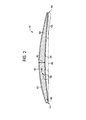
- FIG. 2 shows the convex curved surface or suction side 30 and the concave curved surface or pressure side 34 of blade 10 that extend between leading edge 14 and trailing edge 18.
- the dashed line indicated by 38 that extends from the leading edge 14 to the trailing edge 18 defines the width or chord of blade 10.
- the double-headed arrow indicated by 42 between suction side 30 and pressure side 34 defines the thickness (usually measured as the "maximum" thickness) of blade 10.
- the leading edge section 46 of blade 10 is where the greatest erosion and corrosion damage of airfoil surface 32 tends to occur, particularly with regard to the initiation of erosion or corrosion pitting, especially at or proximate to leading edge 14.
- the area of greatest erosion damage tends to occur in the tip edge portion 50 or area of span 28, especially at or proximate to tip edge 22, and also tends to be focused in the portion 54 or area of pressure side 34 that is directly forward of trailing edge 18 and to a lesser extent in the portion 58 or area of pressure side 34 that is directly aft of leading edge 14.
- the sacrificial and erosion-resistant coatings described here may be disposed over all or any portion of the airfoil surface 32, but are particularly suited for disposition on the portion of airfoil surface 32 that are most susceptible to corrosion and erosion, as described above.
- Turbine compressor airfoils 1 may be made from various stainless steels and superalloys.
- Superalloys include metallic alloys that can be used at high temperatures, often in excess of about 0.7 of the absolute melting temperature. Any Fe-based, Co-based or Ni-based based superalloy composition may be used to form the turbine compressor airfoils 1.
- the most common solutes in Fe-based, Co-based or Ni-based superalloys are aluminum and/or titanium. Generally, the aluminum and/or titanium concentrations are low (e.g., less than or equal to about 15 weight percent (wt %) each).
- Turbine compressor airfoils 1 may be made from various grades of stainless steel, including both 300 series and 400 series stainless steels.
- turbine compressor airfoils 1 may comprise type 450 stainless steel, a martensitic, age-hardenable alloy comprising, by weight, 0.05% carbon, 1.00% manganese, 0.030% phosphorous, 0.030% sulfur, 1.00% silicon, 14.00 to 16.00% chromium, 5.00 to 7.00% nickel, 0.50 to 1.00% molybdenum, 1.25 to 1.75% copper, 0.35 to 0.75% niobium (columbium), and the balance (approximately 72.14 to 77.14%) iron and impurities.
- a martensitic, age-hardenable alloy comprising, by weight, 0.05% carbon, 1.00% manganese, 0.030% phosphorous, 0.030% sulfur, 1.00% silicon, 14.00 to 16.00% chromium, 5.00 to 7.00% nickel, 0.50 to 1.00% molybdenum, 1.25 to 1.75% copper, 0.35 to 0.75% niobium (columbium), and the balance (appro
- the airfoil surface 32 is the surface associated with base segment or substrate 60 of blade 10.
- a multilayer airfoil coating 61 includes at least one sacrificial coating 62 and at least one erosion-resistant coating 64 disposed on airfoil surface 32 of base segment 60. These layers may be disposed on airfoil surface 32 in any order, such that sacrificial coating 62 may be disposed on airfoil surface 32, with erosion-resistant coating 64 being disposed on the surface of sacrificial coating 62.
- erosion-resistant coating 64 may be disposed on airfoil surface 32, with sacrificial coating 62 is disposed on the surface of erosion-resistant coating 64.
- Airfoil coating 61 may also include a plurality of sacrificial layers 62 interspersed within a plurality of erosion-resistant layers 64, such as in all manner of alternating arrangements or sequences, e.g., 62/64/62/64/62/64, 62/64//62.1, 64/62/62.1/64, 62/62.1/62.2/64, 62/62.1/64/62.1/64 and the like, where differences in the tenths digits are used to indicate changes in the sacrificial coating 62 materials and the erosion-resistant-coating 64 materials.
- the structure may be described generally as a turbine compressor airfoil having an airfoil surface 32, a sacrificial coating 62, and an erosion-resistant coating 64, wherein one of the sacrificial coating 62 or the erosion-resistant coating 64 is disposed on the airfoil surface and the other of the sacrificial coating 62 or the erosion-resistant coating 64 is disposed on the respective one.
- Airfoil coating 61 may have any thickness that is effective for providing a predetermined amount of corrosion-resistance and erosion-resistance, including the sum or sums of those described below for the sacrificial coatings and erosion-resistant coatings.
- Airfoil coating 61 is selected such that it imparts suitable corrosion-resistance, particularly with regard to galvanic and crevice corrosion, and erosion resistance, particularly with regard to water droplet erosion, properties to blade 10 at least in the portions or areas 54 and 58 of pressure side 34, typically over the entire or substantially the entire area of pressure side 34, and more typically over the entire or substantially the entire area of pressure side 34 and suction side 30.
- the sacrificial coating 62 is so named because it is anodic relative to the airfoil surface 32. It is also more anodic with reference to the airfoil surface 32 than the erosion-resistant coating 64, hence that sacrificial coating 62 is also anodic relative to erosion-resistant coating 64. Therefore, sacrificial coating 62 is selected so that it is more anodic than either airfoil surface 32 and base segment 60 or erosion-resistant coating 64.
- electromotive force emf
- corrosion potential with respect to a standard thermodynamic reference potential of the sacrificial coating 62 is more negative than that of either airfoil surface 32 or erosion-resistant coating 64 in a corrosive (reactant) species to which turbine compressor airfoil 1 is exposed.
- emf electromotive force
- corrosion potential with respect to a standard thermodynamic reference potential of the sacrificial coating 62 is more negative than that of either airfoil surface 32 or erosion-resistant coating 64 in a corrosive (reactant) species to which turbine compressor airfoil 1 is exposed.
- water droplet erosion this may include potential reactant species associated with water droplets deliberately introduced into the turbine, including those resulting from on-line water washing, fogging and evaporative cooling, or various combinations thereof.
- Reactant species can also result from environments in which the turbines are operating because they are frequently placed in highly corrosive environments, such as those near chemical or petrochemical plants where various chemical species may be found in the intake air, or those at or near ocean coastlines or other saltwater environments where various sea salts, minerals and other seawater constituents may be present in the intake air, or combinations of the above, or in other applications where the inlet air contains corrosive chemical species.
- These species may be ingested together with water droplets from the external environment, or may mix with water droplets that are deliberately introduced, as described above. Without limitation, these species may include various ionic species, including those comprising, Cl - , Br - , F - ,, S 2- , and others.
- sacrificial coating 62 by virtue of its being electrochemically more anodic than airfoil surface 32 and erosion-resistant coating 64, is configured to be attacked preferentially to airfoil surface 32.
- Airfoil surfaces 32 are commonly treated to produce a residual compressive surface stress in order to reduce the tendency of any cracks or pits (or other features that might tend to cause a stress riser at the surface) from propagating from the surface into the interior of the airfoil. Residual compressive stresses may be imparted to airfoil surfaces 32 by shot peening, laser peening or other treatments that also produce residual compressive stresses, or other methods.
- Airfoil coating 61 may also be disposed so as to include residual compressive stresses, particularly compressive stresses that are greater than those of the airfoil surface 32, particularly where airfoil surface 32 includes residual compressive stresses 32.
- a sacrificial coating 62 comprising TiN may have a residual compressive stress of about 3792MPa.
- the turbine compressor airfoils 1 has an airfoil surface 32 with a first residual compressive stress ( ⁇ 1 ), the respective one of the sacrificial coating or the erosion-resistant coating has a second residual compressive stress ( ⁇ 2 ), and the other of the sacrificial coating or the erosion-resistant coating has a third residual compressive stress ( ⁇ 3 ), wherein ⁇ 3 > ⁇ 2 > ⁇ 1 .
- Sacrificial coating 62 may include any suitable coating material comprising Al, Cr, Zn, an Al-based alloy, a Cr-based alloy, or a Zn-based alloy, or a combination thereof, that is more anodic than the airfoil surface 32 or the erosion-resistant coating 64, as described above, and also include various glasses, ceramics, polymers and composites, in any combination, that include these materials. More particularly, in an exemplary embodiment sacrificial coating 62 may include a layer comprising Al, Cr, Zn, an Ni-Al alloy, an Al-Si alloy, an Al-based alloy, a Cr-based alloy or a Zn-based alloy, an Al particle polymer composite, or a combination thereof. This includes the use of these materials in particulate or other forms in various paints and composite materials, including those comprising various polymeric materials, including metal particle pigmented paints, such as aluminum particle pigmented paints having an aluminum content of about 70% or more, by weight.
- the sacrificial layer 62 may be disposed either on the airfoil surface 32 or over the erosion-resistant coating 64, but is particularly suited to being disposed on the airfoil surface 32, as this arrangement places the anodic material in direct electrical contact with the airfoil surface 32, thereby assuring anodic protection of this surface.
- the sacrificial layer 62 may be disposed as a thin film or thick film layer by any suitable application or deposition method, including plating (electro and electroless plating), dipping, spraying, painting, chemical vapor deposition (CVD), or physical vapor deposition (PVD), such as EB-PVD, filtered arc deposition, and more typically by sputtering.
- Suitable sputtering techniques for use herein include but are not limited to direct current diode sputtering, radio frequency sputtering, ion beam sputtering, reactive sputtering, magnetron sputtering and steered arc sputtering.
- Sacrificial coating 62 may include a single layer, or may be provided in multiple layers, including a sacrificial layer that includes a plurality of different materials as sublayers disposed in a contiguous fashion to form a sacrificial layer 62. In a single layer configuration, sacrificial coating 62 may have any suitable thickness needed to provide anodic protection of the airfoil surface 32, including to obtain a predetermined or design service life.
- the thickness of sacrificial coating 62 in the form of a thick film may range from about 120 to 730 microns.
- the thickness of sacrificial coating 62 deposited using a thin film deposition method will generally have a higher density and a thickness in the range of about 5 to 50 microns.
- sacrificial coating 62 may include a layer of a conductive undercoat and an overcoat of an inorganic binder having a plurality of ceramic particles and conductive particles embedded therein disposed on the undercoat, as described in US Patents 5,098,797 and 5,260,099 .
- the conductive undercoat may include a continuous, relatively thin, sacrificial metal layer, such as a layer of a nickel cadmium alloy.
- the nickel cadmium layer may be electroplated to a thickness of about 5 to 10 microns, preferably about 7.6 mils.
- the sacrificial metal undercoat may be provided by flame or plasma spraying techniques in common use, or preferably by applying a metallic paint, such as an aluminum particle/polymer matrix paint, as described above.
- a metallic paint such as an aluminum particle/polymer matrix paint
- the airfoil surface may be initially prepared by grit blasting and then drying, heating to cure and then consolidating the metal powder in contact with the airfoil surface, such as consolidation by glass bead blasting.
- a single application will be sufficient to produce an adequate undercoat of the metallic paint having a thickness in the range described above.
- the overcoat is disposed on the underlayer and includes an inorganic matrix binder having a plurality of ceramic particles and conductive particles embedded therein.
- the inorganic matrix binder includes a phosphate chromate binder having a plurality of aluminum oxide and chromium oxide ceramic particles and aluminum metal particles embedded therein.
- the binder may also include cobalt and other metal or conductive particles.
- the overcoat may be made using the methods disclosed in US 3,248,251 .
- the amount of the embedded metal particles may be selected to make the overcoat more anodic than the airfoil surface 32 or the erosion-resistant layer 64.
- the overcoat may be deposited in any suitable thickness.
- the thickness of the overcoat may be about 3 mils or more.
- the sacrificial layer 62 may be disposed either on the airfoil surface 32 or over the erosion-resistant coating 64, but is particularly suited to being disposed on the surface of the erosion-resistant coating 64, as the sacrificial coating 62 also provides erosion-resistance due to the abrasion resistance associated with and provided by the ceramic material overcoat.
- the erosion-resistant coating 64 portion of airfoil coating 61 may be disposed either on airfoil surface 32 or on the surface of sacrificial coating 62, i.e., either above or under sacrificial coating 62.
- the erosion-resistant layer 64 or layers includes a hard, erosion-resistant layer of a ceramic or a cermet, or a combination thereof.
- the overcoat may also provide some erosion-resistance to the airfoil coating 61 due to the hardness and abrasion resistance of the embedded ceramic particles; however, the phosphate chromate ceramic overcoat alone is not suitable for use as the erosion-resistant layer 64, as disclosed herein, because it does not provide sufficient erosion-resistance owing to its more porous morphology.
- airfoil coating 61 may include a ceramic material as erosion-resistant coating 64.
- Suitable ceramic compositions include metal oxides such as Al 2 O 3 , Cr 2 O 3 , Y 2 O 3 , ZrO 2 , CeO 2 , TiO 2 , Ta 2 O 5 , TaO 2 , and the like; metal carbides such as Cr 3 C 2 , WC, TiC, ZrC, B 4 C, and the like; diamond, diamond-like carbon; metal nitrides such as BN, TiN, ZrN, HfN, CrN, Si 3 N 4 , AIN, TiAIN, TiAlCrN, TiCrN, TiZrN, and the like; metal borides such as TiB 2 , ZrB 2 , Cr 3 B 2 , W 2 B 2 , and the like; and combinations comprising at least one of the foregoing compositions (e.g., TiCN, CrBN, TiBN, and the like).
- metal carbides such as Cr 3 C 2
- the erosion-resistant coating 64 can comprise a ceramic-metal composite (cermet), including those that may be characterized as a metal matrix composite.
- cermets include WC/Co, WC/CoCr, WC/Ni, TiC/Ni,
- suitable compositions include those comprising, in weight percent, 12-20% Co and the balance WC.
- suitable compositions include those comprising, in weight percent, 6-10% Co, 4-8% Cr and the balance WC.
- Still other embodiments of the erosion-resistant coating 64 include combinations comprising at least one of the ceramics or cermets (e.g., a metal or alloy matrix of one of the foregoing).
- This may also include an erosion-resistant coating 64 that has multiple erosion-resistant layers of the same or different erosion-resistant materials, including those that also include interspersed metal layers to promote adherence of the multilayer structure into a cohesive erosion-resistant coating 64.
- an erosion-resistant coating 64 that has multiple erosion-resistant layers of the same or different erosion-resistant materials, including those that also include interspersed metal layers to promote adherence of the multilayer structure into a cohesive erosion-resistant coating 64.
- Cr, Ti or Ta may be used to form strongly adherent interspersed metal layers, particularly where one of these metals is a constituent of the ceramic or cermet, but other metals may also be used.
- a multilayer erosion resistant coating 64 that includes a plurality of layers of Ti and TiN in an alternating arrangement, including any sequential or non-sequential alternating arrangement, such as, for example, Ti/TiN/Ti/TiN/.../Ti/TiN, or TiN/Ti/TiN/Ti.../TiN/Ti, or TiN/Ti/TiN/Ti/.../Ti/TiN, or Ti/TiN/Ti/TiN.../Ti/TiN/Ti.
- the composition may be the stoichiometric compositions shown, as well as various non-stoichiometric variants.
- non-stoichiometric compositions may be employed to introduce residual compressive stress into the crystal lattice, and may be deposited using known methods for their deposition.
- an effective layer thickness includes a minimum thickness of about 5 microns, and single layer thickness in the range of 5-10 microns, and a residual compressive stress of at least about 3792 MPa.
- a minimum thickness per layer of about 5 microns and a maximum overall thickness of about 60 microns is effective.
- An effective thickness range for at least one Ti/TiN combination, and more preferably four or more Ti and TiN layers, is about 5-60 microns, and more particularly about 25-60 microns, and even more particularly about 45-60 microns.
- an effective layer thickness includes a minimum thickness of about 3 mils and single layer thickness in the range of 3-7 mils, and a residual compressive stress of at least about 3792 MPa.
- the minimum thickness will be that effective to provide erosion-resistance greater than that of the bare airfoil surface 32, which generally will be a layer thickness sufficient to insure complete coverage of the surface, including features such as film-cooling holes, etc., while avoiding coating defects sometimes associated with thin layers, such as pinholes.
- the maximum thickness may be any suitable thickness, but will generally be a thickness that is effective to provide a desired service life to the airfoil surface in a predetermined operating environment, while also maintaining a desired level of adherence or bond strength to the airfoil surface 32 or sacrificial coating 62 to which it is applied, as the case may be.
- the maximum thickness will typically be a function of the method used to dispose the erosion-resistant material on the airfoil surface 32 or the sacrificial coating 62, the associated sacrificial coating 62 used and the overall minimum amount of residual compressive stress desired within airfoil coating 61.
- a minimum amount of overall residual compressive stress is desirable in airfoil coating 61 and erosion-resistant coating 64, generally an amount that is at least as large as any minimum amount of residual compressive stress imparted to the airfoil surface 32, so that the airfoil coating 61 does not have the effect of decreasing the residual compressive stress in the airfoil surface 32 below the desired minimum amount, and so that the airfoil coating 61 also maintains the desired minimum amount of residual compressive stress.
- the airfoil coatings 61 including those that include an erosion-resistant coating 64 having a plurality of alternating ceramic (or cermet) and metallic layers, are typically formed by physical vapor deposition (PVD), such as EB-PVD, filtered arc deposition, and more typically by sputtering.
- PVD physical vapor deposition
- Suitable sputtering techniques for use herein include but are not limited to direct current diode sputtering, radio frequency sputtering, ion beam sputtering, reactive sputtering, magnetron sputtering and steered arc sputtering.
- deposition is typically carried out in an atmosphere comprising a source of carbon (e.g., methane) or a source of nitrogen (e.g., nitrogen gas), respectively.
- a source of carbon e.g., methane
- nitrogen e.g., nitrogen gas
- a source or target material that includes the metal borides to be deposited may be used.
- sputtering is typically carried out in an inert atmosphere.
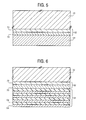
- FIGS. 3-6 Several embodiments of an airfoil 10 having an airfoil surface 32 and an airfoil coating 61 disposed are illustrated in FIGS. 3-6 .
- the airfoil coating 61 includes a sacrificial coating 62 and an erosion-resistant coating 64 of the types described herein, where the sacrificial coating 62 is more anodic than either the airfoil surface 32 or erosion-resistant coating 64.
- a first embodiment of an airfoil 10 and airfoil surface 32 has sacrificial coating 62 disposed on the airfoil surface 32 that includes a layer of Al, Cr, Zn, an Ni-Al alloy, an Al-Si alloy, an Al-based alloy, a Cr-based alloy or a Zn-based alloy, an Al polymer composite, or a combination thereof.
- sacrificial coating 62 Disposed on sacrificial coating 62 is an erosion-resistant coating 64 that includes a layer of a ceramic or cermet 66 material as described herein, such as TiN.
- the sacrificial coating 62 is more anodic than the airfoil surface 32 or the erosion-resistant coating 64, as described above.
- a second embodiment of an airfoil 10 and airfoil surface 32 has sacrificial coating 62 disposed on the airfoil surface 32 that includes a layer of Al, Cr, Zn, an Ni-Al alloy, an Al-Si alloy, an Al-based alloy, a Cr-based alloy or a Zn-based alloy, an Al polymer composite, or a combination thereof.
- an erosion-resistant coating 64 Disposed on sacrificial coating 62 is an erosion-resistant coating 64 that includes a multilayer having an alternating arrangement of metal 68 layers and ceramic (or cermet) 66 layers, as described herein, such as alternating layers of Ti and TiN.
- the sacrificial coating 62 is more anodic than the airfoil surface 32 or the erosion-resistant coating 64, as described above.
- a third embodiment of an airfoil 10 and airfoil surface 32 has sacrificial coating 62 disposed on the airfoil surface 32 that includes a layer of a conductive undercoat and an overcoat of an inorganic matrix binder having a plurality of ceramic particles and conductive particles embedded therein disposed on the undercoat.
- an erosion-resistant coating 64 Disposed on sacrificial coating 62 is an erosion-resistant coating 64 that includes a layer of a ceramic or cermet 66 material as described herein, such as TiN.
- the sacrificial coating 62 is more anodic than the airfoil surface 32 or the erosion-resistant coating 64, as described above.
- a fourth embodiment of an airfoil 10 and airfoil surface 32 has sacrificial coating 62 disposed on the airfoil surface 32 that includes a layer of a conductive undercoat and an overcoat of an inorganic matrix binder having a plurality of ceramic particles and conductive particles embedded therein disposed on the undercoat.
- an erosion-resistant coating 64 Disposed on sacrificial coating 62 is an erosion-resistant coating 64 that includes a multilayer having an alternating arrangement of metal 68 layers and ceramic (or cermet) 66 layers, as described herein, such as alternating layers of Ti and TiN.
- the sacrificial coating 62 is more anodic than the airfoil surface 32 or the erosion-resistant coating 64, as described above.
- a fifth embodiment of an airfoil 10 and airfoil surface 32 has erosion-resistant coating 64 disposed on the airfoil surface 32 that includes a multilayer having an alternating arrangement of metal 68 layers and ceramic (or cermet) 66 layers, as described herein, such as alternating layers of Ti and TiN.
- a sacrificial coating 62 Disposed on erosion-resistant coating 64 is a sacrificial coating 62 that includes a layer of a conductive undercoat and an overcoat of an inorganic matrix binder having a plurality of ceramic particles and conductive particles embedded therein disposed on the undercoat, such as an undercoat layer of a conductive Al paint that includes Al particles in a polymer matrix, and an overcoat layer having a inorganic matrix of a phosphate-chromate ceramic with aluminum oxide, chromium oxide and aluminum particles embedded therein.
- the sacrificial coating 62 is more anodic than the airfoil surface 32 or the erosion-resistant coating 64, as described above.
- Turbine compressor airfoils 1 having an airfoil coating 32 that includes an erosion-resistant coating 64 and sacrificial coating 62 of the types described herein may also include airfoils associated with other turbine components having airfoil surfaces that may be subject to water droplet erosion or crevice corrosion as described herein. These include turbine vanes 100, shrouds 200, combustor liners 300 and other components 400 having airfoil surfaces, as illustrated in FIG. 1 .
- the turbine compressor airfoils disclosed herein may be understood by reference to the following examples.
- Water droplet erosion testing was used to simulate the water impact on the compressor components in the turbine during water wash and water spritz power augmentation. Particle velocity and droplet sizes were controlled to best replicate the turbine environment.
- a series of cylindrical test coupons of Custom 450 stainless steel were coated with several erosion-resistant coatings including a single layer of TiN having a thickness of about 6 to 8 microns, a multilayer of a plurality Ti and TiN, each having a minimum thickness of 5 microns and having an overall thickness of about 45 microns, and a layer of WC-CoCr having a composition, in weight percent, of 10% Co, 4% Cr and the balance WC and a thickness of about 4-6 mils.
- Test coupons having these erosion-resistant coatings were tested in a rotary test fixture where the test coupons were attached to the outboard end of the leading edge of a motor-driven five-foot blade.
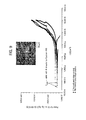
- the apparatus was designed to rotate the blade and test coupons through a continuous spray of water droplets with a DV90 of 740 microns at a speed of 800 feet/sec. The tests were run until the onset of erosive pitting was observed and the time to pitting was noted. The results are shown in FIG. 8 .
- the test demonstrated that the erosion-resistant coatings were effective to improve the water droplet erosion-resistance of Custom 450 stainless steel. All of the erosion-resistant coatings showed a substantial improvement in erosion resistance relative to the bare Custom 450 surface.
- Custom -450 test coupons coated with the airfoil coatings described herein were coated with an airfoil coating including a sheet of Custom 450 as the airfoil surface, a 50 micron thick coating of Al deposited by an air plasma spray (APS) process and a 150 micron thick coating of WC-CoCr deposited by Hyper-velocity oxy-fuel (HVOF) spray process.
- the test was an accelerated corrosion test for assessing coating performance.
- the area ratios of the above coating system and the Custom 450 pin edge was kept at 150:1 in order to simulate defects in the actual coating system that would be exposed to field conditions. Due to difference in electrochemical corrosion potentials of Custom 450 and the two-layer coating system, currents would flow through the external circuit as they were shorted and the current levels were monitored through a Zero Resistance Ammeter (ZRA).
- ZRA Zero Resistance Ammeter
- the galvanic potential between the coating and the substrate were also monitored and was near -850mV vs. Ag-Ag-AgCl reference electrode. From Fig.
Landscapes
- Chemical & Material Sciences (AREA)
- Engineering & Computer Science (AREA)
- Mechanical Engineering (AREA)
- Organic Chemistry (AREA)
- Materials Engineering (AREA)
- Metallurgy (AREA)
- Chemical Kinetics & Catalysis (AREA)
- Inorganic Chemistry (AREA)
- General Engineering & Computer Science (AREA)
- Ceramic Engineering (AREA)
- Physics & Mathematics (AREA)
- Plasma & Fusion (AREA)
- Structures Of Non-Positive Displacement Pumps (AREA)
- Turbine Rotor Nozzle Sealing (AREA)
- Other Surface Treatments For Metallic Materials (AREA)
Abstract
Description
- The subject matter disclosed herein relates to turbine compressor airfoils, including turbine compressor airfoils, having improved corrosion and erosion resistance, and methods of manufacturing these turbine compressor airfoils. More particularly, it relates to turbine compressor airfoils having turbine compressor airfoil coatings that provide improved corrosion and erosion resistance, and methods of manufacturing coated turbine compressor airfoils.
- Stainless steel turbine compressor airfoils, such as those used in the compressors of industrial gas turbines, have shown susceptibility to water droplet erosion and corrosion pitting of the airfoil surfaces. These are believed to be associated with various electrochemical dissolution processes enabled by the impingement of the water droplets, and other chemical species present in the droplets, intake air or both of them, on the airfoil surface. Electrochemically-induced corrosion and erosion phenomena occurring at the airfoil surfaces can in turn result in cracking of the airfoils due to the cyclic thermal and operating stresses experienced by these components. Water droplet exposure can result from use of on-line water washing, fogging and evaporative cooling, or various combinations of these processes, to enhance compressor efficiency. It can also result from the environments in which the turbines are operating because they are frequently placed in highly corrosive environments, such as those near chemical or petrochemical plants where various chemical species may be found in the intake air, or those at or near ocean coastlines or other saltwater environments where various sea salts may be present in the intake air, or combinations of the above, or in other applications where the inlet air contains corrosive chemical species.
- A material change to use other materials for the turbine compressor airfoils, such as nickel-base or titanium-base alloys, is one approach for improving erosion resistance, corrosion resistance, or both, but this may not solve the water droplet erosion or corrosion pitting problems, since these materials may also have susceptibility to the associated electrochemical processes. Further, using materials other than stainless steels to improve the corrosion and erosion resistance of compressor blades is generally not desirable because they are not cost effective replacements, due to the higher cost of the alloy constituents. These materials are generally also not desirable because their use requires redesign of the turbine blades, including the turbine compressor airfoil surfaces, due to the fact that they have different metallurgical and mechanical properties. Further, the use of materials such as nickel-base or titanium-base alloys may not provide better overall robustness of the turbine blades, including turbine compressor airfoils, because they are sensitive to other degradation phenomena, such as various rub and fretting wear mechanisms.
- Corrosion resistant airfoil coatings and methods of making steel airfoils with corrosion resistant coatings are described in
US Patents 5,098,797 and5,260,099 , respectively. These patents describe a corrosion resistant coating that includes a sacrificial undercoat of a metal standing above iron in the electromotive series and a ceramic overcoat that included a mixture of chromium oxide, aluminum oxide and silicon oxide. The ceramic material was applied at a temperature of 600°F or less to avoid reduction of the fatigue resistance of the type 403 stainless steel airfoil alloy. - While various approaches to improve the erosion or corrosion resistance of stainless steel turbine compressor airfoils have been proposed, stainless steel turbine compressor airfoils having improved resistance to both erosion and corrosion would be desirable.
- According to one aspect of the invention, a sacrificial and erosion-resistant turbine compressor airfoil includes a turbine compressor airfoil having an airfoil surface. The airfoil surface has an airfoil coating that includes a sacrificial coating comprising a layer of at least one of Al, Cr, Zn, an Ni-Al alloy, an Al-Si alloy, an Al-based alloy, a Cr-based alloy or a Zn-based alloy, an Al polymer composite, or a combination thereof, or a layer of a conductive undercoat and an overcoat of an inorganic matrix binder having a plurality of ceramic particles and conductive particles embedded therein disposed on the undercoat. The airfoil coating also includes an erosion-resistant coating, wherein one of the sacrificial coating or the erosion-resistant coating is disposed on the airfoil surface and the other of the sacrificial coating or the erosion-resistant coating is disposed on the respective one, and wherein the sacrificial coating is more anodic than the airfoil surface or the erosion-resistant coating.
- According to another aspect of the invention, a method of making a sacrificial and erosion-resistant turbine compressor airfoil includes providing a turbine compressor airfoil having a modified airfoil surface. The method also includes disposing one of a sacrificial coating or an erosion-resistant coating on the airfoil surface, the sacrificial coating comprising a layer of at least one of Al, Cr, Zn, an Ni-Al alloy, an Al-Si alloy, an Al-based alloy, a Cr-based alloy or a Zn-based alloy, an Al polymer composite, or a combination thereof, or a layer of a conductive undercoat and an overcoat of an inorganic matrix binder having a plurality of ceramic particles and conductive particles embedded therein disposed on the undercoat. The method also includes disposing the other of the sacrificial coating or the erosion-resistant coating on the respective one that is disposed on the airfoil surface, wherein the sacrificial coating is more anodic with reference to the airfoil surface than the erosion-resistant coating.
- These and other advantages and features will become more apparent from the following description taken in conjunction with the drawings.
- The subject matter which is regarded as the invention is particularly pointed out and distinctly claimed in the claims at the conclusion of the specification. The foregoing and other features, and advantages of the invention are apparent from the following detailed description taken in conjunction with the accompanying drawings by way of example in which:
-
FIG. 1 is perspective view of a turbine compressor airfoil, in the form of a turbine blade, as disclosed herein; -
FIG. 2 is a cross-sectional view of section 2-2 ofFIG. 1 ; -
FIG 3 . is a cross-sectional view of an embodiment ofregion 90 ofFIG. 2 ; -
FIG 4 . is a cross-sectional view of a second embodiment ofregion 90 ofFIG. 2 ; -
FIG. 5 is a cross-sectional view of a third embodiment ofregion 90 ofFIG. 2 ; -
FIG. 6 is a cross-sectional view of a fourth embodiment ofregion 90 ofFIG. 2 ; -
FIG. 7 is a cross-sectional view of a fifth embodiment ofregion 90 ofFIG. 2 ; -
FIG. 8 is a plot illustrating the erosion and corrosion performance of various turbine compressor airfoils, as disclosed herein; -
FIG. 9 is a plot of electrochemical potential as a function of current for an embodiment of a turbine compressor airfoil as disclosed herein; and -
FIG. 10 is a plot of electrochemical potential and monitored corrosion current as a function of time for a test pin representative of an embodiment of a turbine compressor airfoil as disclosed herein. - The detailed description explains embodiments of the invention, together with advantages and features, by way of example with reference to the drawings.
- A sacrificial and erosion-resistant turbine compressor airfoil is disclosed having an airfoil surface and an airfoil coating disposed thereon. The airfoil coating includes a sacrificial coating and an erosion-resistant coating, and is particularly useful for turbine compressor airfoil applications, including rotating compressor blades, stationary compressor vanes, shrouds and other airfoil surfaces within the turbine that may be subject to water droplet erosion and pitting and crevice corrosion. One of the sacrificial coating or the erosion-resistant coating is disposed on the airfoil surface and the other of the sacrificial coating or the erosion-resistant coating is disposed on the respective one. The -sacrificial coating is more anodic with reference to the airfoil surface than the erosion-resistant coating. The coating system provides enhanced water droplet erosion protection, enhanced galvanic and crevice corrosion resistance, and improved surface finish and antifouling capability for turbine compressor airfoil applications. The coating system takes advantage of the excellent solid particle and water droplet erosion resistance of TiN or a WCCoCr alloy, including multilayer Ti/TiN structures where the layers of Ti and TiN are placed in an alternating arrangement. The coating system also takes advantage of the excellent galvanic corrosion resistance provided by at least one layer of Al, Cr, Zn, an Al-based alloy, a Cr-based alloy, or a Zn-based alloy, or a combination thereof; or a layer of a conductive undercoat and an overcoat of a ceramic material disposed on the undercoat. Both single and multi-layer systems have been found to be water droplet erosion resistant. It has been discovered that the coatings protect the substrate in erosive and corrosive environments. The coatings may be strategically placed and coating thicknesses designed to provide specific water droplet erosion and pitting corrosion benefits for turbine compressor airfoil applications.
- As used herein, the term "comprising" means various compositions, compounds, components, layers, steps and the like can be conjointly employed in the present invention. Accordingly, the term "comprising" encompasses the more restrictive terms "consisting essentially of" and "consisting of."
- The embodiments of the
turbine compressor airfoils 1 disclosed herein have improved particle impact and water droplet erosion resistance and crevice corrosion resistance. They includeturbine compressor airfoils 1 that can be removably attached to a central hub or disk, as well as turbine compressor airfoils 1 integral with the hub or disk, i.e., a turbine blisk. However, while the embodiments herein are illustrated with reference toturbine compressor airfoils 1 in the form ofturbine blades 10, they are broadly applicable to all manner ofturbine compressor airfoils 1 used in a wide variety of turbine engine components. These includeturbine compressor airfoils 1 associated withturbine vanes 100 and nozzles,shrouds 200,combustor liners 300 and other 400 turbine compressor airfoils, i.e., turbine components having airfoil surfaces such as diaphragm components, seal components, valve stems, nozzle boxes, nozzle plates, or the like. - Referring to
FIG. 1 , a typicalturbine compressor airfoil 1 in the form ofturbine compressor blade 10 is illustrated. Blade 10 has a leadingedge 14, atrailing edge 18, atip edge 22 and ablade root 26. Thespan 28 ofblade 10 extends fromtip edge 22 toblade root 26. The surface ofblade 10 comprehended within thespan 28 constitutes theairfoil surface 32 ofturbine compressor airfoil 1.Airfoil surface 32 is that portion ofturbine compressor airfoil 1 that is exposed to the flow path of air from the turbine inlet (not shown) through the compressor section of the turbine into the combustion chamber and other portions of the turbine. -
FIG. 2 shows the convex curved surface orsuction side 30 and the concave curved surface orpressure side 34 ofblade 10 that extend between leadingedge 14 andtrailing edge 18. The dashed line indicated by 38 that extends from the leadingedge 14 to thetrailing edge 18 defines the width or chord ofblade 10. The double-headed arrow indicated by 42 betweensuction side 30 andpressure side 34 defines the thickness (usually measured as the "maximum" thickness) ofblade 10. - Referring to
FIG. 2 , theleading edge section 46 ofblade 10 is where the greatest erosion and corrosion damage ofairfoil surface 32 tends to occur, particularly with regard to the initiation of erosion or corrosion pitting, especially at or proximate to leadingedge 14. Referring toFIGS. 1 and2 , the area of greatest erosion damage tends to occur in thetip edge portion 50 or area ofspan 28, especially at or proximate to tipedge 22, and also tends to be focused in theportion 54 or area ofpressure side 34 that is directly forward of trailingedge 18 and to a lesser extent in theportion 58 or area ofpressure side 34 that is directly aft of leadingedge 14. The sacrificial and erosion-resistant coatings described here may be disposed over all or any portion of theairfoil surface 32, but are particularly suited for disposition on the portion ofairfoil surface 32 that are most susceptible to corrosion and erosion, as described above. -
Turbine compressor airfoils 1 may be made from various stainless steels and superalloys. Superalloys include metallic alloys that can be used at high temperatures, often in excess of about 0.7 of the absolute melting temperature. Any Fe-based, Co-based or Ni-based based superalloy composition may be used to form theturbine compressor airfoils 1. The most common solutes in Fe-based, Co-based or Ni-based superalloys are aluminum and/or titanium. Generally, the aluminum and/or titanium concentrations are low (e.g., less than or equal to about 15 weight percent (wt %) each). Other optional components include chromium, molybdenum, cobalt (in Fe-based or Ni-based superalloys), tungsten, nickel (in Fe-based or Co-based superalloys), rhenium, iron (in Co-based or Ni-based superalloys), tantalum, vanadium, hafnium, columbium, ruthenium, zirconium, boron, yttrium, and carbon, each of which may independently be present in an amount of less than or equal to about 15 wt %.Turbine compressor airfoils 1 may be made from various grades of stainless steel, including both 300 series and 400 series stainless steels. More particularly,turbine compressor airfoils 1 may comprise type 450 stainless steel, a martensitic, age-hardenable alloy comprising, by weight, 0.05% carbon, 1.00% manganese, 0.030% phosphorous, 0.030% sulfur, 1.00% silicon, 14.00 to 16.00% chromium, 5.00 to 7.00% nickel, 0.50 to 1.00% molybdenum, 1.25 to 1.75% copper, 0.35 to 0.75% niobium (columbium), and the balance (approximately 72.14 to 77.14%) iron and impurities. - The
airfoil surface 32 is the surface associated with base segment orsubstrate 60 ofblade 10. As also shown inFIGS. 3-7 to prevent erosion and corrosion or enhance erosion resistance and corrosion resistance, a multilayer airfoil coating 61 includes at least onesacrificial coating 62 and at least one erosion-resistant coating 64 disposed onairfoil surface 32 ofbase segment 60. These layers may be disposed onairfoil surface 32 in any order, such thatsacrificial coating 62 may be disposed onairfoil surface 32, with erosion-resistant coating 64 being disposed on the surface ofsacrificial coating 62. Alternately, an opposite ordering may be used, such that erosion-resistant coating 64 may be disposed onairfoil surface 32, withsacrificial coating 62 is disposed on the surface of erosion-resistant coating 64. Airfoil coating 61 may also include a plurality ofsacrificial layers 62 interspersed within a plurality of erosion-resistant layers 64, such as in all manner of alternating arrangements or sequences, e.g., 62/64/62/64/62/64, 62/64//62.1, 64/62/62.1/64, 62/62.1/62.2/64, 62/62.1/64/62.1/64 and the like, where differences in the tenths digits are used to indicate changes in thesacrificial coating 62 materials and the erosion-resistant-coating 64 materials. Hence, the structure may be described generally as a turbine compressor airfoil having anairfoil surface 32, asacrificial coating 62, and an erosion-resistant coating 64, wherein one of thesacrificial coating 62 or the erosion-resistant coating 64 is disposed on the airfoil surface and the other of thesacrificial coating 62 or the erosion-resistant coating 64 is disposed on the respective one. Airfoil coating 61 may have any thickness that is effective for providing a predetermined amount of corrosion-resistance and erosion-resistance, including the sum or sums of those described below for the sacrificial coatings and erosion-resistant coatings. Airfoil coating 61 is selected such that it imparts suitable corrosion-resistance, particularly with regard to galvanic and crevice corrosion, and erosion resistance, particularly with regard to water droplet erosion, properties toblade 10 at least in the portions orareas pressure side 34, typically over the entire or substantially the entire area ofpressure side 34, and more typically over the entire or substantially the entire area ofpressure side 34 andsuction side 30. - The
sacrificial coating 62 is so named because it is anodic relative to theairfoil surface 32. It is also more anodic with reference to theairfoil surface 32 than the erosion-resistant coating 64, hence thatsacrificial coating 62 is also anodic relative to erosion-resistant coating 64. Therefore,sacrificial coating 62 is selected so that it is more anodic than eitherairfoil surface 32 andbase segment 60 or erosion-resistant coating 64. By more anodic, it is meant that the electromotive force (emf) or corrosion potential with respect to a standard thermodynamic reference potential of thesacrificial coating 62 is more negative than that of eitherairfoil surface 32 or erosion-resistant coating 64 in a corrosive (reactant) species to whichturbine compressor airfoil 1 is exposed. With regard to water droplet erosion, this may include potential reactant species associated with water droplets deliberately introduced into the turbine, including those resulting from on-line water washing, fogging and evaporative cooling, or various combinations thereof. Reactant species can also result from environments in which the turbines are operating because they are frequently placed in highly corrosive environments, such as those near chemical or petrochemical plants where various chemical species may be found in the intake air, or those at or near ocean coastlines or other saltwater environments where various sea salts, minerals and other seawater constituents may be present in the intake air, or combinations of the above, or in other applications where the inlet air contains corrosive chemical species. These species may be ingested together with water droplets from the external environment, or may mix with water droplets that are deliberately introduced, as described above. Without limitation, these species may include various ionic species, including those comprising, Cl-, Br-, F-,, S2-, and others. Together with the water droplets, these species are capable of participating in various electrochemical reactions and thereby causing electrochemical erosion and corrosion of theairfoil surface 32. By use of the airfoil coating 61,sacrificial coating 62, by virtue of its being electrochemically more anodic than airfoilsurface 32 and erosion-resistant coating 64, is configured to be attacked preferentially toairfoil surface 32. - Reference herein to the
sacrificial coating 62 being disposed on either theairfoil surface 32 or erosion-resistant coating 64 means that it is attached and tightly adherent to these surfaces, preferably by virtue of chemical or metallurgical bonding, such that it is able to undergo normal operating and thermal stresses without exhibiting spalling or other coating degradation processes. Airfoil surfaces 32 are commonly treated to produce a residual compressive surface stress in order to reduce the tendency of any cracks or pits (or other features that might tend to cause a stress riser at the surface) from propagating from the surface into the interior of the airfoil. Residual compressive stresses may be imparted to airfoil surfaces 32 by shot peening, laser peening or other treatments that also produce residual compressive stresses, or other methods. Airfoil coating 61 may also be disposed so as to include residual compressive stresses, particularly compressive stresses that are greater than those of theairfoil surface 32, particularly where airfoil surface 32 includes residual compressive stresses 32. As an example, asacrificial coating 62 comprising TiN may have a residual compressive stress of about 3792MPa. Theturbine compressor airfoils 1 has anairfoil surface 32 with a first residual compressive stress (σ1), the respective one of the sacrificial coating or the erosion-resistant coating has a second residual compressive stress (σ2), and the other of the sacrificial coating or the erosion-resistant coating has a third residual compressive stress (σ3), wherein σ3>σ2>σ1. -
Sacrificial coating 62 may include any suitable coating material comprising Al, Cr, Zn, an Al-based alloy, a Cr-based alloy, or a Zn-based alloy, or a combination thereof, that is more anodic than theairfoil surface 32 or the erosion-resistant coating 64, as described above, and also include various glasses, ceramics, polymers and composites, in any combination, that include these materials. More particularly, in an exemplary embodimentsacrificial coating 62 may include a layer comprising Al, Cr, Zn, an Ni-Al alloy, an Al-Si alloy, an Al-based alloy, a Cr-based alloy or a Zn-based alloy, an Al particle polymer composite, or a combination thereof. This includes the use of these materials in particulate or other forms in various paints and composite materials, including those comprising various polymeric materials, including metal particle pigmented paints, such as aluminum particle pigmented paints having an aluminum content of about 70% or more, by weight. - The
sacrificial layer 62 may be disposed either on theairfoil surface 32 or over the erosion-resistant coating 64, but is particularly suited to being disposed on theairfoil surface 32, as this arrangement places the anodic material in direct electrical contact with theairfoil surface 32, thereby assuring anodic protection of this surface. Thesacrificial layer 62 may be disposed as a thin film or thick film layer by any suitable application or deposition method, including plating (electro and electroless plating), dipping, spraying, painting, chemical vapor deposition (CVD), or physical vapor deposition (PVD), such as EB-PVD, filtered arc deposition, and more typically by sputtering. Suitable sputtering techniques for use herein include but are not limited to direct current diode sputtering, radio frequency sputtering, ion beam sputtering, reactive sputtering, magnetron sputtering and steered arc sputtering.Sacrificial coating 62 may include a single layer, or may be provided in multiple layers, including a sacrificial layer that includes a plurality of different materials as sublayers disposed in a contiguous fashion to form asacrificial layer 62. In a single layer configuration,sacrificial coating 62 may have any suitable thickness needed to provide anodic protection of theairfoil surface 32, including to obtain a predetermined or design service life. For example, the thickness ofsacrificial coating 62 in the form of a thick film, such as a metal particle/polymer matrix paint, may range from about 120 to 730 microns. The thickness ofsacrificial coating 62 deposited using a thin film deposition method will generally have a higher density and a thickness in the range of about 5 to 50 microns. - In another exemplary embodiment,
sacrificial coating 62 may include a layer of a conductive undercoat and an overcoat of an inorganic binder having a plurality of ceramic particles and conductive particles embedded therein disposed on the undercoat, as described inUS Patents 5,098,797 and5,260,099 . In particular, the conductive undercoat may include a continuous, relatively thin, sacrificial metal layer, such as a layer of a nickel cadmium alloy. The nickel cadmium layer may be electroplated to a thickness of about 5 to 10 microns, preferably about 7.6 mils. Alternately, the sacrificial metal undercoat may be provided by flame or plasma spraying techniques in common use, or preferably by applying a metallic paint, such as an aluminum particle/polymer matrix paint, as described above. When using the metallic paint, the airfoil surface may be initially prepared by grit blasting and then drying, heating to cure and then consolidating the metal powder in contact with the airfoil surface, such as consolidation by glass bead blasting. Generally, a single application will be sufficient to produce an adequate undercoat of the metallic paint having a thickness in the range described above. The overcoat is disposed on the underlayer and includes an inorganic matrix binder having a plurality of ceramic particles and conductive particles embedded therein. In one embodiment, the inorganic matrix binder includes a phosphate chromate binder having a plurality of aluminum oxide and chromium oxide ceramic particles and aluminum metal particles embedded therein. The binder may also include cobalt and other metal or conductive particles. The overcoat may be made using the methods disclosed inUS 3,248,251 . The amount of the embedded metal particles may be selected to make the overcoat more anodic than theairfoil surface 32 or the erosion-resistant layer 64. The overcoat may be deposited in any suitable thickness. In one embodiment, where the inorganic matrix binder is a phosphate chromate binder, having aluminum oxide and chromium oxide ceramic particles and aluminum metal particles embedded therein, the thickness of the overcoat may be about 3 mils or more. In this embodiment, where thesacrificial coating 62 includes a conductive undercoat/overcoat, thesacrificial layer 62 may be disposed either on theairfoil surface 32 or over the erosion-resistant coating 64, but is particularly suited to being disposed on the surface of the erosion-resistant coating 64, as thesacrificial coating 62 also provides erosion-resistance due to the abrasion resistance associated with and provided by the ceramic material overcoat. - As noted above, the erosion-
resistant coating 64 portion of airfoil coating 61 may be disposed either onairfoil surface 32 or on the surface ofsacrificial coating 62, i.e., either above or undersacrificial coating 62. The erosion-resistant layer 64 or layers includes a hard, erosion-resistant layer of a ceramic or a cermet, or a combination thereof. Where thesacrificial coating 62 includes a conductive undercoat/overcoat as described above, such as the phosphate chromate inorganic matrix binder, the overcoat may also provide some erosion-resistance to the airfoil coating 61 due to the hardness and abrasion resistance of the embedded ceramic particles; however, the phosphate chromate ceramic overcoat alone is not suitable for use as the erosion-resistant layer 64, as disclosed herein, because it does not provide sufficient erosion-resistance owing to its more porous morphology. - As noted, airfoil coating 61 may include a ceramic material as erosion-
resistant coating 64. Suitable ceramic compositions include metal oxides such as Al2O3, Cr2O3, Y2O3, ZrO2, CeO2, TiO2, Ta2O5, TaO2, and the like; metal carbides such as Cr3C2, WC, TiC, ZrC, B4C, and the like; diamond, diamond-like carbon; metal nitrides such as BN, TiN, ZrN, HfN, CrN, Si3N4, AIN, TiAIN, TiAlCrN, TiCrN, TiZrN, and the like; metal borides such as TiB2, ZrB2, Cr3B2, W2B2, and the like; and combinations comprising at least one of the foregoing compositions (e.g., TiCN, CrBN, TiBN, and the like). Alternately, the erosion-resistant coating 64 can comprise a ceramic-metal composite (cermet), including those that may be characterized as a metal matrix composite. Suitable cermets include WC/Co, WC/CoCr, WC/Ni, TiC/Ni, - TiC/Fe, Ni(Cr)/Cr3C2, TaC/Ni, and combinations comprising at least one of the foregoing. In the case of WC-Co cermets, suitable compositions include those comprising, in weight percent, 12-20% Co and the balance WC. In the case of WC-CoCr cermets, suitable compositions include those comprising, in weight percent, 6-10% Co, 4-8% Cr and the balance WC. Still other embodiments of the erosion-
resistant coating 64 include combinations comprising at least one of the ceramics or cermets (e.g., a metal or alloy matrix of one of the foregoing). This may also include an erosion-resistant coating 64 that has multiple erosion-resistant layers of the same or different erosion-resistant materials, including those that also include interspersed metal layers to promote adherence of the multilayer structure into a cohesive erosion-resistant coating 64. For many of these materials, Cr, Ti or Ta may be used to form strongly adherent interspersed metal layers, particularly where one of these metals is a constituent of the ceramic or cermet, but other metals may also be used. For example, a multilayer erosionresistant coating 64 that includes a plurality of layers of Ti and TiN in an alternating arrangement, including any sequential or non-sequential alternating arrangement, such as, for example, Ti/TiN/Ti/TiN/.../Ti/TiN, or TiN/Ti/TiN/Ti.../TiN/Ti, or TiN/Ti/TiN/Ti/.../Ti/TiN, or Ti/TiN/Ti/TiN.../Ti/TiN/Ti. Of the erosion-resistant ceramic and cermet materials, single layers TiN or WCCoCr, or a multilayer structure that includes a plurality of layers of Ti and TiN, have been tested and are particularly suitable for use as erosion-resistant coating 64. In the case of both the ceramic and cermet materials mentioned above, the composition may be the stoichiometric compositions shown, as well as various non-stoichiometric variants. For example, non-stoichiometric compositions may be employed to introduce residual compressive stress into the crystal lattice, and may be deposited using known methods for their deposition. - Any suitable thickness of a single layer and a multilayer erosion-
resistant coating 64 may be used, so long as it is effective to provide increased erosion resistance over that of the material ofairfoil surface 32. In one embodiment, for a single layer of TiN, an effective layer thickness includes a minimum thickness of about 5 microns, and single layer thickness in the range of 5-10 microns, and a residual compressive stress of at least about 3792 MPa. In another embodiment of a multilayer that includes a plurality of Ti and TiN layers in an alternating arrangement, a minimum thickness per layer of about 5 microns and a maximum overall thickness of about 60 microns (with at least four layers of Ti and TiN) is effective. An effective thickness range for at least one Ti/TiN combination, and more preferably four or more Ti and TiN layers, is about 5-60 microns, and more particularly about 25-60 microns, and even more particularly about 45-60 microns. In yet another exemplary embodiment of a single layer of WCCoCr as the erosion-resistant coating 64, an effective layer thickness includes a minimum thickness of about 3 mils and single layer thickness in the range of 3-7 mils, and a residual compressive stress of at least about 3792 MPa. The minimum thickness will be that effective to provide erosion-resistance greater than that of thebare airfoil surface 32, which generally will be a layer thickness sufficient to insure complete coverage of the surface, including features such as film-cooling holes, etc., while avoiding coating defects sometimes associated with thin layers, such as pinholes. The maximum thickness may be any suitable thickness, but will generally be a thickness that is effective to provide a desired service life to the airfoil surface in a predetermined operating environment, while also maintaining a desired level of adherence or bond strength to theairfoil surface 32 orsacrificial coating 62 to which it is applied, as the case may be. The maximum thickness will typically be a function of the method used to dispose the erosion-resistant material on theairfoil surface 32 or thesacrificial coating 62, the associatedsacrificial coating 62 used and the overall minimum amount of residual compressive stress desired within airfoil coating 61. A minimum amount of overall residual compressive stress is desirable in airfoil coating 61 and erosion-resistant coating 64, generally an amount that is at least as large as any minimum amount of residual compressive stress imparted to theairfoil surface 32, so that the airfoil coating 61 does not have the effect of decreasing the residual compressive stress in theairfoil surface 32 below the desired minimum amount, and so that the airfoil coating 61 also maintains the desired minimum amount of residual compressive stress. - The airfoil coatings 61, including those that include an erosion-
resistant coating 64 having a plurality of alternating ceramic (or cermet) and metallic layers, are typically formed by physical vapor deposition (PVD), such as EB-PVD, filtered arc deposition, and more typically by sputtering. Suitable sputtering techniques for use herein include but are not limited to direct current diode sputtering, radio frequency sputtering, ion beam sputtering, reactive sputtering, magnetron sputtering and steered arc sputtering. In forming the ceramic layers that include carbides or nitrides, deposition is typically carried out in an atmosphere comprising a source of carbon (e.g., methane) or a source of nitrogen (e.g., nitrogen gas), respectively. In the case of borides, a source or target material that includes the metal borides to be deposited may be used. In forming the metallic layers, sputtering is typically carried out in an inert atmosphere. - Several embodiments of an
airfoil 10 having anairfoil surface 32 and an airfoil coating 61 disposed are illustrated inFIGS. 3-6 . The airfoil coating 61 includes asacrificial coating 62 and an erosion-resistant coating 64 of the types described herein, where thesacrificial coating 62 is more anodic than either theairfoil surface 32 or erosion-resistant coating 64. - Referring to
FIG. 3 , a first embodiment of anairfoil 10 andairfoil surface 32 hassacrificial coating 62 disposed on theairfoil surface 32 that includes a layer of Al, Cr, Zn, an Ni-Al alloy, an Al-Si alloy, an Al-based alloy, a Cr-based alloy or a Zn-based alloy, an Al polymer composite, or a combination thereof. Disposed onsacrificial coating 62 is an erosion-resistant coating 64 that includes a layer of a ceramic orcermet 66 material as described herein, such as TiN. Thesacrificial coating 62 is more anodic than theairfoil surface 32 or the erosion-resistant coating 64, as described above. - Referring to
FIG. 4 , a second embodiment of anairfoil 10 andairfoil surface 32 hassacrificial coating 62 disposed on theairfoil surface 32 that includes a layer of Al, Cr, Zn, an Ni-Al alloy, an Al-Si alloy, an Al-based alloy, a Cr-based alloy or a Zn-based alloy, an Al polymer composite, or a combination thereof. Disposed onsacrificial coating 62 is an erosion-resistant coating 64 that includes a multilayer having an alternating arrangement ofmetal 68 layers and ceramic (or cermet) 66 layers, as described herein, such as alternating layers of Ti and TiN. Thesacrificial coating 62 is more anodic than theairfoil surface 32 or the erosion-resistant coating 64, as described above. - Referring to
FIG. 5 , a third embodiment of anairfoil 10 andairfoil surface 32 hassacrificial coating 62 disposed on theairfoil surface 32 that includes a layer of a conductive undercoat and an overcoat of an inorganic matrix binder having a plurality of ceramic particles and conductive particles embedded therein disposed on the undercoat. Disposed onsacrificial coating 62 is an erosion-resistant coating 64 that includes a layer of a ceramic orcermet 66 material as described herein, such as TiN. Thesacrificial coating 62 is more anodic than theairfoil surface 32 or the erosion-resistant coating 64, as described above. - Referring to
FIG. 6 , a fourth embodiment of anairfoil 10 andairfoil surface 32 hassacrificial coating 62 disposed on theairfoil surface 32 that includes a layer of a conductive undercoat and an overcoat of an inorganic matrix binder having a plurality of ceramic particles and conductive particles embedded therein disposed on the undercoat. Disposed onsacrificial coating 62 is an erosion-resistant coating 64 that includes a multilayer having an alternating arrangement ofmetal 68 layers and ceramic (or cermet) 66 layers, as described herein, such as alternating layers of Ti and TiN. Thesacrificial coating 62 is more anodic than theairfoil surface 32 or the erosion-resistant coating 64, as described above. - Referring to
FIG. 7 , a fifth embodiment of anairfoil 10 andairfoil surface 32 has erosion-resistant coating 64 disposed on theairfoil surface 32 that includes a multilayer having an alternating arrangement ofmetal 68 layers and ceramic (or cermet) 66 layers, as described herein, such as alternating layers of Ti and TiN. Disposed on erosion-resistant coating 64 is asacrificial coating 62 that includes a layer of a conductive undercoat and an overcoat of an inorganic matrix binder having a plurality of ceramic particles and conductive particles embedded therein disposed on the undercoat, such as an undercoat layer of a conductive Al paint that includes Al particles in a polymer matrix, and an overcoat layer having a inorganic matrix of a phosphate-chromate ceramic with aluminum oxide, chromium oxide and aluminum particles embedded therein. Thesacrificial coating 62 is more anodic than theairfoil surface 32 or the erosion-resistant coating 64, as described above. - While the
turbine compressor airfoils 1 disclosed herein have been described above with particular reference to an embodiment of aturbine blade 10.Turbine compressor airfoils 1 having anairfoil coating 32 that includes an erosion-resistant coating 64 andsacrificial coating 62 of the types described herein may also include airfoils associated with other turbine components having airfoil surfaces that may be subject to water droplet erosion or crevice corrosion as described herein. These includeturbine vanes 100, shrouds 200,combustor liners 300 andother components 400 having airfoil surfaces, as illustrated inFIG. 1 . The turbine compressor airfoils disclosed herein may be understood by reference to the following examples. - Water droplet erosion testing was used to simulate the water impact on the compressor components in the turbine during water wash and water spritz power augmentation. Particle velocity and droplet sizes were controlled to best replicate the turbine environment. A series of cylindrical test coupons of Custom 450 stainless steel were coated with several erosion-resistant coatings including a single layer of TiN having a thickness of about 6 to 8 microns, a multilayer of a plurality Ti and TiN, each having a minimum thickness of 5 microns and having an overall thickness of about 45 microns, and a layer of WC-CoCr having a composition, in weight percent, of 10% Co, 4% Cr and the balance WC and a thickness of about 4-6 mils. Test coupons having these erosion-resistant coatings were tested in a rotary test fixture where the test coupons were attached to the outboard end of the leading edge of a motor-driven five-foot blade. The apparatus was designed to rotate the blade and test coupons through a continuous spray of water droplets with a DV90 of 740 microns at a speed of 800 feet/sec. The tests were run until the onset of erosive pitting was observed and the time to pitting was noted. The results are shown in
FIG. 8 . The test demonstrated that the erosion-resistant coatings were effective to improve the water droplet erosion-resistance of Custom 450 stainless steel. All of the erosion-resistant coatings showed a substantial improvement in erosion resistance relative to the bare Custom 450 surface. - In a second test, polarization scans and galvanic corrosion tests were performed on Custom -450 test coupons coated with the airfoil coatings described herein. A series of test coupons of Custom 450 stainless steel were coated with an airfoil coating including a sheet of Custom 450 as the airfoil surface, a 50 micron thick coating of Al deposited by an air plasma spray (APS) process and a 150 micron thick coating of WC-CoCr deposited by Hyper-velocity oxy-fuel (HVOF) spray process. The test conditions included 5% NaCl (similar to salt-fog chloride levels), that was acidic having a pH=4.0 at 50 degree Celsius to simulate condensing gases with moisture and salt. The test was an accelerated corrosion test for assessing coating performance. It utilized a cyclic polarization corrosion test according to ASTM G61 with creviced Custom 450 coupons. Ceramic washers torqued down by associated threaded bolts to 40 in-lb were used for crevicing the test coupons. Absence of hysteresis in the cyclic polarization loop and a post-examination photomicrograph of the test coupon, as shown in
FIG. 9 , revealed the absence of any crevice corrosion, and visual examination revealed no red rust or other evidence that corrosion of Custom 450 occurred during the cyclic polarization scan. The corrosion potential or potential under steady-state unpolarized (actual operating) conditions for this coating system is ∼ -840 mV. This is about 550 mV below the corrosion potential or Ecorr of bare Custom 450 exposed to 5% NaCl, under similar pH and temperature conditions which is about -300 mV. Hence the coating system is said to be anodic or sacrificial relative to the Custom 450 substrate in acidic chloride media. Hence such a system that includes a sacrificial coating (Al) and an erosion-resistant coating (WC-CoCr) is suitable for providing erosion and corrosion resistance in a turbine compressor airfoil environment. Both creviced and un-creviced coupon showed similar polarization behavior, namely absence of crevice corrosion and similar corrosion rates. In another experiment, the above coating system was externally shorted electrically to a Custom 450 pin edge and both were exposed to a similar 5% NaCl solution at pH=4.0 and 50°C. The area ratios of the above coating system and the Custom 450 pin edge was kept at 150:1 in order to simulate defects in the actual coating system that would be exposed to field conditions. Due to difference in electrochemical corrosion potentials of Custom 450 and the two-layer coating system, currents would flow through the external circuit as they were shorted and the current levels were monitored through a Zero Resistance Ammeter (ZRA). The galvanic potential between the coating and the substrate were also monitored and was near -850mV vs. Ag-Ag-AgCl reference electrode. FromFig. 10 , it can be seen that a steady state current of about 1.0 micro amps were monitored between the coating and the Custom 450 pin substrate. Based on the positive current magnitude and the direction, the coating is sacrificial in that the coating corrodes preferentially to the substrate. Thus, even in field conditions, the coating would protect the substrate against galvanic corrosion even if there is a breach of the coating to an extent that would allow corrosive species to reach the substrate. - While the invention has been described in detail in connection with only a limited number of embodiments, it should be readily understood that the invention is not limited to such disclosed embodiments. Rather, the invention can be modified to incorporate any number of variations, alterations, substitutions or equivalent arrangements not heretofore described, but which are commensurate with the spirit and scope of the invention. Additionally, while various embodiments of the invention have been described, it is to be understood that aspects of the invention may include only some of the described embodiments. Accordingly, the invention is not to be seen as limited by the foregoing description, but is only limited by the scope of the appended claims.
Claims (15)
- A turbine compressor airfoil, comprising:a turbine compressor airfoil having an airfoil surface;a sacrificial coating comprising a layer of Al, Cr, Zn, an Ni-Al alloy, an Al-Si alloy, an Al-based alloy, a Cr-based alloy or a Zn-based alloy, an Al polymer composite, or a combination thereof, or a layer of a conductive undercoat and an overcoat of an inorganic matrix binder having a plurality of ceramic particles and conductive particles embedded therein disposed on the undercoat; andan erosion-resistant coating, wherein one of the sacrificial coating or the erosion-resistant coating is disposed on the airfoil surface and the other of the sacrificial coating or the erosion-resistant coating is disposed on the respective one, and wherein the sacrificial coating is more anodic than the airfoil surface or the erosion-resistant coating.
- The turbine compressor airfoil of claim 1, wherein the airfoil surface comprises a stainless steel or a superalloy.
- The turbine compressor airfoil of claim 1 or claim 2, wherein the erosion-resistant coating comprises a layer of a ceramic or a cermet.
- The turbine compressor airfoil of any preceding claim, wherein the erosion-resistant coating is a ceramic comprising a metal oxide, nitride, carbide, boride, carbonitride, oxynitride, boronitride, diamond, diamond-like carbon, or a combination thereof.
- The turbine compressor airfoil of any preceding claim, wherein the erosion-resistant coating comprises a layer of Al2O3, Cr2O3, Y2O3, ZrO2, CeO2, TiO2, Ta2O5, TaO2, Cr3C2, WC, TiC, ZrC, B4C, diamond, diamond-like carbon, BN, TiN, ZrN, HfN, CrN, Si3N4, AIN, TiAIN, TiAlCrN, TiCrN, TiZrN, TiB2, ZrB2, Cr3B2, W2B2, TiCN, CrBN, TiBN, WC-Co, WC-CoCr, WC-Ni, TiC-Ni, TiC-Fe, Ni(Cr)-Cr3C2, or TaC-Ni, or a combination thereof.
- The turbine compressor airfoil of any preceding claim, wherein the erosion-resistant coating is a single layer of the ceramic or the cermet.
- The turbine compressor airfoil of claim 6, further comprising a layer of a metal disposed under the layer of the ceramic or the cermet.
- The turbine compressor airfoil of any preceding claim, wherein the erosion-resistant coating further comprises a plurality of metal layers and a plurality of ceramic or cermet layers.
- The turbine compressor airfoil of claim 8, wherein the metal layers and the ceramic or cermet layers have an alternating arrangement.
- The turbine compressor airfoil of claim 8, wherein the metal layers comprise Ti and the ceramic or cermet layers comprise TiN layers.
- The turbine compressor airfoil of any one of claims 1 to 10, wherein the sacrificial coating is disposed on the airfoil surface and the erosion-resistant coating is disposed on the sacrificial coating.
- The turbine compressor airfoil of any one of claims 1 to 10, wherein the erosion-resistant coating is disposed on the airfoil surface and the sacrificial coating is disposed on the erosion-resistant coating.
- The turbine compressor airfoil of claim 11 or claim 12, wherein the erosion-resistant coating comprises a layer of TiN or WCCoCr and the sacrificial coating comprises a layer of a conductive undercoat and an overcoat of an inorganic matrix binder having a plurality of ceramic particles and conductive particles embedded therein.
- The turbine compressor airfoil of claim 11 or claim 12, wherein the erosion-resistant coating comprises a layer of TiN or WCCoCr and the sacrificial coating comprises a layer of Al, Cr, Zn, an Ni-Al alloy, an Al-Si alloy, an Al-based alloy, a Cr-based alloy or a Zn-based alloy, an Al polymer composite, or a combination thereof.
- A method of making a turbine compressor airfoil, comprising:providing a turbine compressor airfoil having an airfoil surface;disposing one of a sacrificial coating or an erosion-resistant coating on the airfoil surface, the sacrificial coating comprising a layer of Al, Cr, Zn, an Ni-Al alloy, an Al-Si alloy, an Al-based alloy, a Cr-based alloy or a Zn-based alloy, an Al polymer composite, or a combination thereof, or a layer of a conductive undercoat and an overcoat of an inorganic matrix binder having a plurality of ceramic particles and conductive particles embedded therein disposed on the undercoat; anddisposing the other of the sacrificial coating or the erosion-resistant coating on the respective one that is disposed on the airfoil surface, wherein the corrosion resistant coating is more anodic with reference to the airfoil surface than the erosion-resistant coating.
Applications Claiming Priority (1)
| Application Number | Priority Date | Filing Date | Title |
|---|---|---|---|
| US12/399,261 US20100226783A1 (en) | 2009-03-06 | 2009-03-06 | Erosion and Corrosion Resistant Turbine Compressor Airfoil and Method of Making the Same |
Publications (2)
| Publication Number | Publication Date |
|---|---|
| EP2226409A2 true EP2226409A2 (en) | 2010-09-08 |
| EP2226409A3 EP2226409A3 (en) | 2011-03-02 |
Family
ID=42079134
Family Applications (1)
| Application Number | Title | Priority Date | Filing Date |
|---|---|---|---|
| EP10155190A Withdrawn EP2226409A3 (en) | 2009-03-06 | 2010-03-02 | Erosion and corrosion resistant turbine compressor airfoil and method of making the same |
Country Status (4)
| Country | Link |
|---|---|
| US (1) | US20100226783A1 (en) |
| EP (1) | EP2226409A3 (en) |
| JP (1) | JP2010209913A (en) |
| CN (1) | CN101876327A (en) |
Cited By (18)
| Publication number | Priority date | Publication date | Assignee | Title |
|---|---|---|---|---|
| US20100226783A1 (en) * | 2009-03-06 | 2010-09-09 | General Electric Company | Erosion and Corrosion Resistant Turbine Compressor Airfoil and Method of Making the Same |
| EP2366813A3 (en) * | 2010-03-05 | 2011-12-21 | General Electric Company | Layered Article |
| GB2481399A (en) * | 2010-06-22 | 2011-12-28 | Bernard John Boyle | A component coated with tungsten carbide, zinc and PTFE |
| EP2631323A1 (en) * | 2012-02-22 | 2013-08-28 | Sikorsky Aircraft Corporation | Erosion and fatigue resistant blade and blade coating |
| RU2520281C2 (en) * | 2012-01-11 | 2014-06-20 | Открытое Акционерное Общество "Уральский научно-исследовательский институт композиционных материалов" | Carbon-carbon composite material |
| EP2754733A1 (en) * | 2013-01-14 | 2014-07-16 | Siemens Aktiengesellschaft | Anti-corrosion and anti-erosion protective coating |
| EP2913421A1 (en) * | 2014-02-28 | 2015-09-02 | General Electric Company | Coated article and method for production coating |
| EP2855083B1 (en) | 2012-05-29 | 2016-06-15 | SNECMA Services | Method for compacting anodic paints, including the collision of sandblasting jets |
| EP3054095A1 (en) * | 2015-02-05 | 2016-08-10 | Mitsubishi Hitachi Power Systems, Ltd. | Steam turbine and surface treatment method therefor |
| EP2971247A4 (en) * | 2013-03-15 | 2016-11-02 | United Technologies Corp | IMPROVED PROTECTION FOR ALUMINUM FAN BLADES USING A SACRIFICIAL LAYER |
| EP3112597A1 (en) * | 2015-07-02 | 2017-01-04 | Airbus Defence and Space GmbH | Temperature-resistant turbine blade made with a layer of oxide ceramics |
| EP3040363A4 (en) * | 2013-08-30 | 2017-04-26 | Kabushiki Kaisha Toshiba | Erosion resistant material and turbine blade |
| EP3423611A1 (en) * | 2016-03-03 | 2019-01-09 | Vetco Gray Scandinavia AS | System and method for cathodic protection by distributed sacrificial anodes |
| EP3049632B1 (en) * | 2013-09-27 | 2020-06-24 | United Technologies Corporation | Fan blade assembly |
| CN111826599A (en) * | 2018-11-12 | 2020-10-27 | 中国兵器工业第五九研究所 | A kind of high-performance composite coating suitable for titanium alloy and preparation method thereof |
| CN117282641A (en) * | 2023-10-07 | 2023-12-26 | 江苏商贸职业学院 | Rust-proof coating, coating process and equipment |
| US20240318564A1 (en) * | 2019-07-08 | 2024-09-26 | Pratt & Whitney Canada Corp. | Pulse-managed plasma method for coating on internal surfaces of workpieces |
| US12534809B2 (en) | 2022-11-15 | 2026-01-27 | General Electric Company | Coating composition, coated turbine component, and method of applying the coating |
Families Citing this family (46)
| Publication number | Priority date | Publication date | Assignee | Title |
|---|---|---|---|---|
| CN102133571B (en) * | 2011-01-24 | 2012-12-26 | 南通宝钢钢铁有限公司 | Method for preparing chloride ion corrosion resistant bar material with nano composite coating |
| GB201106276D0 (en) * | 2011-04-14 | 2011-05-25 | Rolls Royce Plc | Annulus filler system |
| CN103302916B (en) | 2012-03-16 | 2016-08-17 | 深圳富泰宏精密工业有限公司 | Film-coated part and preparation method thereof |
| CN103374694A (en) * | 2012-04-24 | 2013-10-30 | 中国石油天然气股份有限公司 | A preparation method for corrosion-resistant composite coating for oil pipe |
| US20130323066A1 (en) * | 2012-05-31 | 2013-12-05 | Monika D. Kinstler | Maskant for fluoride ion cleaning |
| US9365932B2 (en) | 2012-06-20 | 2016-06-14 | General Electric Company | Erosion and corrosion resistant coatings for exhaust gas recirculation based gas turbines |
| EP2767616A1 (en) * | 2013-02-15 | 2014-08-20 | Alstom Technology Ltd | Turbomachine component with an erosion and corrosion resistant coating system and method for manufacturing such a component |
| US20140272166A1 (en) * | 2013-03-13 | 2014-09-18 | Rolls-Royce Corporation | Coating system for improved leading edge erosion protection |
| CN103161733B (en) * | 2013-03-15 | 2015-04-08 | 鲁东大学 | Ti / TiCrN nanometer multilayer coating impeller and preparation method thereof |
| JP2014238014A (en) * | 2013-06-06 | 2014-12-18 | 株式会社Ihi | Compressor blade and compressor blade of aircraft jet engine and surface treatment method therefor |
| CA2917916A1 (en) | 2013-07-09 | 2015-02-05 | United Technologies Corporation | Plated polymer nosecone |
| EP3019705B1 (en) | 2013-07-09 | 2019-01-30 | United Technologies Corporation | High-modulus coating for local stiffening of airfoil trailing edges |
| CA2917922A1 (en) * | 2013-07-09 | 2015-01-15 | United Technologies Corporation | Erosion and wear protection for composites and plated polymers |
| WO2015006421A1 (en) | 2013-07-09 | 2015-01-15 | United Technologies Corporation | Metal-encapsulated polymeric article |
| US11268526B2 (en) | 2013-07-09 | 2022-03-08 | Raytheon Technologies Corporation | Plated polymer fan |
| US10927843B2 (en) | 2013-07-09 | 2021-02-23 | Raytheon Technologies Corporation | Plated polymer compressor |
| WO2015047756A1 (en) | 2013-09-27 | 2015-04-02 | United Technologies Corporation | Fan blade assembly |
| US20160298644A1 (en) | 2013-09-27 | 2016-10-13 | United Technologies Corporation | Fan blade assembly |
| US10513942B2 (en) * | 2013-12-10 | 2019-12-24 | United Technologies Corporation | Fusible bond for gas turbine engine coating system |
| CN103710692A (en) * | 2013-12-20 | 2014-04-09 | 苏州市邦成电子科技有限公司 | Preparation method of corrosion-resistant SUS301 stainless steel band |
| EP2907888A1 (en) * | 2014-02-14 | 2015-08-19 | Siemens Aktiengesellschaft | Compressor blade with erosion resistant hard material coating |
| WO2015155119A1 (en) | 2014-04-09 | 2015-10-15 | Nuovo Pignone Srl | Method of protecting a component of a turbomachine from liquid droplets erosion, component and turbomachine |
| US20150308275A1 (en) * | 2014-04-29 | 2015-10-29 | General Electric Company | Coating method and coated article |
| US9896585B2 (en) * | 2014-10-08 | 2018-02-20 | General Electric Company | Coating, coating system, and coating method |
| US10041361B2 (en) * | 2014-10-15 | 2018-08-07 | General Electric Company | Turbine blade coating composition |
| CA2965607C (en) | 2014-12-25 | 2019-07-23 | Ihi Corporation | Exfoliative coating for compressor vane or blade |
| JP2016196820A (en) * | 2015-04-02 | 2016-11-24 | 株式会社Ihi | Engine compressor blade |
| US9982684B2 (en) * | 2015-08-07 | 2018-05-29 | General Electric Company | Hybrid metal compressor blades |
| CN108070836A (en) * | 2016-11-18 | 2018-05-25 | 中国科学院金属研究所 | A kind of preparation method of anti-superhigh temperature oxidation ZrC/TaC micro-laminated coatings |
| CN106811728A (en) * | 2017-03-16 | 2017-06-09 | 江苏海德曼新材料股份有限公司 | A kind of rub resistance erosion resistance coating material and preparation method thereof |
| GB201802468D0 (en) * | 2018-02-15 | 2018-04-04 | Rolls Royce Plc | Coated substrate |
| CN109139549B (en) * | 2018-08-08 | 2021-05-25 | 合肥通用机械研究院有限公司 | Wear-resistant and corrosion-resistant carbon fiber axial flow fan blade device |
| US20220018012A1 (en) | 2018-11-08 | 2022-01-20 | Oerlikon Surface Solutions Ag, Pfäffikon | Corrosion resistant coatings |
| WO2020098967A1 (en) | 2018-11-13 | 2020-05-22 | Oerlikon Surface Solutions Ag, Pfäffikon | Coated article exhibiting high corrosion and erosion resistance including ain-layer |
| JP7214120B2 (en) * | 2018-11-27 | 2023-01-30 | 株式会社神戸製鋼所 | Hard-coated member and its manufacturing method |
| CA3043564C (en) * | 2019-05-15 | 2026-02-10 | Safran | Process for shaping a layer of alumina on the surface of a metallic substrate |
| CN111139421B (en) * | 2020-01-13 | 2021-10-01 | 中航装甲科技有限公司 | Preparation method of composite coating for light composite armor ceramic |
| CN111500989B (en) * | 2020-04-24 | 2021-11-02 | 中国科学院兰州化学物理研究所 | A kind of preparation method and application of anti-wear and anti-corrosion protective film |
| DE102020206202A1 (en) | 2020-05-18 | 2021-11-18 | MTU Aero Engines AG | Blade for a turbomachine with blade tip armor and anti-erosion layer and method for producing the same |
| CN111676478A (en) * | 2020-06-16 | 2020-09-18 | 浙江工业大学 | A kind of preparation method of corrosion-resistant alloy layer on the surface of GCr15 steel |
| CN112876223B (en) * | 2021-03-11 | 2024-08-30 | 成都拓维高科光电科技有限公司 | A preparation method of corrosion-resistant gradient stainless steel surface coating and precision electronic components |
| CN113578297B (en) * | 2021-08-27 | 2024-02-27 | 陕西科技大学 | Oxygen-terminated monolayer titanium carbide composite titanium dioxide photocatalyst and preparation method thereof |
| CN115094373B (en) * | 2022-08-23 | 2022-11-22 | 北京辰融科技有限责任公司 | Surface deposition process method for blade disc and blade tip |
| US12404776B2 (en) | 2023-04-14 | 2025-09-02 | Rolls-Royce North American Technologies, Inc. | Airfoil with protective coating |
| US12228037B1 (en) * | 2023-12-04 | 2025-02-18 | General Electric Company | Guide vane assembly with fixed and variable pitch inlet guide vanes |
| CN119876847B (en) * | 2025-02-17 | 2025-10-28 | 西安理工大学 | High-temperature oxidation-resistant and wear-resistant composite coating on surface of cast high-temperature alloy and preparation method thereof |
Citations (3)
| Publication number | Priority date | Publication date | Assignee | Title |
|---|---|---|---|---|
| US3248251A (en) | 1963-06-28 | 1966-04-26 | Teleflex Inc | Inorganic coating and bonding composition |
| US5098797A (en) | 1990-04-30 | 1992-03-24 | General Electric Company | Steel articles having protective duplex coatings and method of production |
| US5260099A (en) | 1990-04-30 | 1993-11-09 | General Electric Company | Method of making a gas turbine blade having a duplex coating |
Family Cites Families (16)
| Publication number | Priority date | Publication date | Assignee | Title |
|---|---|---|---|---|
| US3261673A (en) * | 1963-05-17 | 1966-07-19 | Norton Co | Oxide coated articles with metal undercoat |
| US4741975A (en) * | 1984-11-19 | 1988-05-03 | Avco Corporation | Erosion-resistant coating system |
| US4839245A (en) * | 1985-09-30 | 1989-06-13 | Union Carbide Corporation | Zirconium nitride coated article and method for making same |
| US4904528A (en) * | 1987-12-24 | 1990-02-27 | United Technologies Corporation | Coated gas turbine engine compressor components |
| RU2352686C2 (en) * | 2003-09-29 | 2009-04-20 | ДЖЕНЕРАЛ ЭЛЕКТРИК КОМПАНИ (э Нью-Йорк Корпорейшн) | Nano-structural coating system, components and corresponding methods of manufacturing |
| US7186092B2 (en) * | 2004-07-26 | 2007-03-06 | General Electric Company | Airfoil having improved impact and erosion resistance and method for preparing same |
| US7186090B2 (en) * | 2004-08-05 | 2007-03-06 | General Electric Company | Air foil shape for a compressor blade |
| CN1657653A (en) * | 2005-04-01 | 2005-08-24 | 中国航空工业第一集团公司北京航空材料研究院 | High-temp. alloy surface heat barrier coating and its preparation method |
| US20080102296A1 (en) * | 2006-10-26 | 2008-05-01 | Farshad Ghasripoor | Erosion resistant coatings and methods of making |
| EP2129812B1 (en) * | 2007-03-27 | 2013-04-17 | Alstom Technology Ltd | Turbomachine blade with erosion and corrosion protective coating and method of manufacturing the same |
| US8113787B2 (en) * | 2007-06-20 | 2012-02-14 | Alstom Technology Ltd. | Turbomachine blade with erosion and corrosion protective coating and method of manufacturing |
| US20100247321A1 (en) * | 2008-01-08 | 2010-09-30 | General Electric Company | Anti-fouling coatings and articles coated therewith |
| US20090176110A1 (en) * | 2008-01-08 | 2009-07-09 | General Electric Company | Erosion and corrosion-resistant coating system and process therefor |
| US8790789B2 (en) * | 2008-05-29 | 2014-07-29 | General Electric Company | Erosion and corrosion resistant coatings, methods and articles |
| DE102009010110B4 (en) * | 2009-02-21 | 2014-08-28 | MTU Aero Engines AG | Erosion protection coating system for gas turbine components |
| US20100226783A1 (en) * | 2009-03-06 | 2010-09-09 | General Electric Company | Erosion and Corrosion Resistant Turbine Compressor Airfoil and Method of Making the Same |
-
2009
- 2009-03-06 US US12/399,261 patent/US20100226783A1/en not_active Abandoned
-
2010
- 2010-03-02 EP EP10155190A patent/EP2226409A3/en not_active Withdrawn
- 2010-03-04 JP JP2010047302A patent/JP2010209913A/en not_active Withdrawn
- 2010-03-08 CN CN2010101394784A patent/CN101876327A/en active Pending
Patent Citations (4)
| Publication number | Priority date | Publication date | Assignee | Title |
|---|---|---|---|---|
| US3248251A (en) | 1963-06-28 | 1966-04-26 | Teleflex Inc | Inorganic coating and bonding composition |
| US5098797A (en) | 1990-04-30 | 1992-03-24 | General Electric Company | Steel articles having protective duplex coatings and method of production |
| US5260099A (en) | 1990-04-30 | 1993-11-09 | General Electric Company | Method of making a gas turbine blade having a duplex coating |
| US5098797B1 (en) | 1990-04-30 | 1997-07-01 | Gen Electric | Steel articles having protective duplex coatings and method of production |
Cited By (22)
| Publication number | Priority date | Publication date | Assignee | Title |
|---|---|---|---|---|
| US20100226783A1 (en) * | 2009-03-06 | 2010-09-09 | General Electric Company | Erosion and Corrosion Resistant Turbine Compressor Airfoil and Method of Making the Same |
| EP2366813A3 (en) * | 2010-03-05 | 2011-12-21 | General Electric Company | Layered Article |
| GB2481399A (en) * | 2010-06-22 | 2011-12-28 | Bernard John Boyle | A component coated with tungsten carbide, zinc and PTFE |
| RU2520281C2 (en) * | 2012-01-11 | 2014-06-20 | Открытое Акционерное Общество "Уральский научно-исследовательский институт композиционных материалов" | Carbon-carbon composite material |
| US9404172B2 (en) | 2012-02-22 | 2016-08-02 | Sikorsky Aircraft Corporation | Erosion and fatigue resistant blade and blade coating |
| EP2631323A1 (en) * | 2012-02-22 | 2013-08-28 | Sikorsky Aircraft Corporation | Erosion and fatigue resistant blade and blade coating |
| EP2855083B1 (en) | 2012-05-29 | 2016-06-15 | SNECMA Services | Method for compacting anodic paints, including the collision of sandblasting jets |
| EP2754733A1 (en) * | 2013-01-14 | 2014-07-16 | Siemens Aktiengesellschaft | Anti-corrosion and anti-erosion protective coating |
| EP2971247A4 (en) * | 2013-03-15 | 2016-11-02 | United Technologies Corp | IMPROVED PROTECTION FOR ALUMINUM FAN BLADES USING A SACRIFICIAL LAYER |
| US10301950B2 (en) | 2013-03-15 | 2019-05-28 | United Technologies Corporation | Enhanced protection for aluminum fan blade via sacrificial layer |
| EP3040363A4 (en) * | 2013-08-30 | 2017-04-26 | Kabushiki Kaisha Toshiba | Erosion resistant material and turbine blade |
| US10082035B2 (en) | 2013-08-30 | 2018-09-25 | Kabushiki Kaisha Toshiba | Erosion resistant material and turbine blade |
| EP3049632B1 (en) * | 2013-09-27 | 2020-06-24 | United Technologies Corporation | Fan blade assembly |
| EP2913421A1 (en) * | 2014-02-28 | 2015-09-02 | General Electric Company | Coated article and method for production coating |
| EP3054095A1 (en) * | 2015-02-05 | 2016-08-10 | Mitsubishi Hitachi Power Systems, Ltd. | Steam turbine and surface treatment method therefor |
| EP3112597A1 (en) * | 2015-07-02 | 2017-01-04 | Airbus Defence and Space GmbH | Temperature-resistant turbine blade made with a layer of oxide ceramics |
| EP3423611A1 (en) * | 2016-03-03 | 2019-01-09 | Vetco Gray Scandinavia AS | System and method for cathodic protection by distributed sacrificial anodes |
| EP3423611B1 (en) * | 2016-03-03 | 2026-08-12 | Vetco Gray Scandinavia AS | System and method for cathodic protection by distributed sacrificial anodes |
| CN111826599A (en) * | 2018-11-12 | 2020-10-27 | 中国兵器工业第五九研究所 | A kind of high-performance composite coating suitable for titanium alloy and preparation method thereof |
| US20240318564A1 (en) * | 2019-07-08 | 2024-09-26 | Pratt & Whitney Canada Corp. | Pulse-managed plasma method for coating on internal surfaces of workpieces |
| US12534809B2 (en) | 2022-11-15 | 2026-01-27 | General Electric Company | Coating composition, coated turbine component, and method of applying the coating |
| CN117282641A (en) * | 2023-10-07 | 2023-12-26 | 江苏商贸职业学院 | Rust-proof coating, coating process and equipment |
Also Published As
| Publication number | Publication date |
|---|---|
| JP2010209913A (en) | 2010-09-24 |
| CN101876327A (en) | 2010-11-03 |
| EP2226409A3 (en) | 2011-03-02 |
| US20100226783A1 (en) | 2010-09-09 |
Similar Documents
| Publication | Publication Date | Title |
|---|---|---|
| US20100226783A1 (en) | Erosion and Corrosion Resistant Turbine Compressor Airfoil and Method of Making the Same | |
| EP2088225B1 (en) | Erosion and corrosion-resistant coating system and process therefor | |
| US20100247321A1 (en) | Anti-fouling coatings and articles coated therewith | |
| Mehta et al. | Role of thermal spray coatings on wear, erosion and corrosion behavior: a review | |
| EP3374539B1 (en) | Turbine clearance control coatings and method | |
| El Rayes et al. | Erosion-corrosion of cermet coating | |
| Rajendran | Gas turbine coatings–An overview | |
| JP5441596B2 (en) | Surface treatment of turbine components to reduce particle accumulation during turbine operation | |
| CN101169048A (en) | Anti-corrosion coating and its preparation method | |
| US20140166473A1 (en) | Erosion and corrosion resistant components and methods thereof | |
| Pavithran et al. | Effect of Yttria-stabilized zirconia coating on the corrosion and thermal behaviour of additive manufactured Inconel 718 alloy | |
| Gurrappa et al. | The importance of corrosion and the necessity of applying intelligent coatings for its control | |
| US8196600B1 (en) | High-temperature jointed assemblies and wear-resistant coating systems therefor | |
| CN116904905A (en) | Method of forming a coating system on a surface and method of repairing an existing coating system | |
| Singh et al. | Corrosion behavior of plasma-sprayed coatings on a Ni-base superalloy in Na2SO4-60 Pct V2O5 environment at 900° C | |
| Tucker | An overview of alternative coatings for wear and corrosion resistance | |
| Menasri et al. | Experimental investigation on the coating of nickel-base super alloy using wire flame spraying | |
| US20220018012A1 (en) | Corrosion resistant coatings | |
| WO2020098967A1 (en) | Coated article exhibiting high corrosion and erosion resistance including ain-layer | |
| Restall | Surface degradation and protective treatments | |
| WO2022174973A2 (en) | Coated article combining high corrosion and erosion resistance | |
| Chavan et al. | Characterization of Ti-31 Alloy Coated with WC–Co/Cr by HVOF Technique | |
| EP2913421A1 (en) | Coated article and method for production coating | |
| Sharma et al. | Heat Treatment of Thermal Spray Coatings: A Review | |
| Yadav et al. | Slurry erosive wear study of d-gun sprayed coatings on SAE 431 |
Legal Events
| Date | Code | Title | Description |
|---|---|---|---|
| PUAI | Public reference made under article 153(3) epc to a published international application that has entered the european phase |
Free format text: ORIGINAL CODE: 0009012 |
|
| AK | Designated contracting states |
Kind code of ref document: A2 Designated state(s): AT BE BG CH CY CZ DE DK EE ES FI FR GB GR HR HU IE IS IT LI LT LU LV MC MK MT NL NO PL PT RO SE SI SK SM TR |
|
| PUAL | Search report despatched |
Free format text: ORIGINAL CODE: 0009013 |
|
| AK | Designated contracting states |
Kind code of ref document: A3 Designated state(s): AT BE BG CH CY CZ DE DK EE ES FI FR GB GR HR HU IE IS IT LI LT LU LV MC MK MT NL NO PL PT RO SE SI SK SM TR |
|
| RIC1 | Information provided on ipc code assigned before grant |
Ipc: C23C 28/00 20060101AFI20100504BHEP Ipc: C23C 30/00 20060101ALI20110121BHEP Ipc: F01D 5/28 20060101ALI20110121BHEP Ipc: C23C 4/06 20060101ALI20110121BHEP |
|
| 17P | Request for examination filed |
Effective date: 20110902 |
|
| STAA | Information on the status of an ep patent application or granted ep patent |
Free format text: STATUS: THE APPLICATION IS DEEMED TO BE WITHDRAWN |
|
| 18D | Application deemed to be withdrawn |
Effective date: 20131001 |