EP2226239A1 - Crawler type travel device - Google Patents
Crawler type travel device Download PDFInfo
- Publication number
- EP2226239A1 EP2226239A1 EP08863612A EP08863612A EP2226239A1 EP 2226239 A1 EP2226239 A1 EP 2226239A1 EP 08863612 A EP08863612 A EP 08863612A EP 08863612 A EP08863612 A EP 08863612A EP 2226239 A1 EP2226239 A1 EP 2226239A1
- Authority
- EP
- European Patent Office
- Prior art keywords
- crawler belt
- crawler
- driving wheel
- belt
- type traveling
- Prior art date
- Legal status (The legal status is an assumption and is not a legal conclusion. Google has not performed a legal analysis and makes no representation as to the accuracy of the status listed.)
- Granted
Links
Images






Classifications
-
- B—PERFORMING OPERATIONS; TRANSPORTING
- B62—LAND VEHICLES FOR TRAVELLING OTHERWISE THAN ON RAILS
- B62D—MOTOR VEHICLES; TRAILERS
- B62D55/00—Endless track vehicles
- B62D55/08—Endless track units; Parts thereof
- B62D55/18—Tracks
- B62D55/24—Tracks of continuously flexible type, e.g. rubber belts
- B62D55/253—Tracks of continuously flexible type, e.g. rubber belts having elements interconnected by one or more cables or like elements
Definitions
- the present invention relates to a traveling device for a crawler type vehicle. More specifically, the present invention relates to a crawler type traveling device for a space robot and a space exploration vehicle, and a crawler type vehicle comprising such crawler type traveling devices.
- the ground surfaces of a moon and planets are usually not stable ground. Instead, such ground surfaces are usually covered by sand, and thus have poor bearing power. Further, when a vehicle travels on the moon and planets on which the gravity is lower than that on earth, it is necessary to distribute the weight of the vehicle over a wide area, and to lower the pressure contacting the ground when traveling.
- One type of prior art space exploration vehicle has four to eight cylindrical wheels for enabling wide a ground area to be contacted. In such vehicle having wheels, the pressure contacting the ground is at a maximum under the wheels. Thus, the wheels are likely to be buried under the sand, and it would be difficult to continue traveling.
- crawler type vehicle which comprises a driving wheel, idler wheels and a crawler belt spooled over the driving wheel and the idler wheel, and travels on the ground using the crawler belt.
- the crawler type vehicle contacts a wide area of ground, and thus has a good traveling capability even on a soft ground.
- the crawler type traveling device comprises a crawler belt having a plurality of crawler plates made of a rigid metal, the crawler plates being pivotally connected to adjacent plates by pins.
- the crawler belt goes around the driving wheel and the idler wheels.
- Another crawler belt is made of a rubber having flexibility, and does not have crawler plates connected by pins.
- a crawler type vehicle needs a lot of rotating wheel mechanisms for equalizing the pressure contacting the ground.
- this mechanism is complicated and heavy, and reliability is degraded thereby.
- Patent Document 1 JP 2005-111595 discloses a crawler type traveling robot comprising a base, a crawler provided on each of the right and left sides of the base, and an arm provided on the base.
- Each crawler comprises a driving wheel provided at one end thereof in a longitudinal direction, a traveling motor for driving the driving wheel, an idling wheel provided at the other end thereof in a longitudinal direction, an endless track engaging the driving wheel and idling wheel and spooled around both wheels, a center wheel engaging the endless track at the center portion of the crawler and a central motor for driving the center wheel.
- the crawler type traveling robot shown in patent document 1 does not contact the ground with uniform pressure. Further, there is a possibility that stones or sand will easily enter into the engaging portions of the crawler belt and the driving wheel.
- Patent Document 1 JP 2005-111595
- An object of the present invention is to provide a crawler belt with no movable portion connected by pins etc., and thus to provide a crawler type traveling device which has no lubricating problem.
- An object of the present invention is to provide a crawler type traveling device with few rotating wheel mechanisms which equalizes the pressure thereof contacting the ground.
- Another object of the present invention is to provide a crawler type traveling device in which stones or sand will not easily enter into the engaging portions of the crawler belt and the driving wheel.
- a further object of the present invention is to provide a crawler type vehicle having such crawler type traveling devices.
- a crawler belt (assembly) comprises a double crawlers configuration having an outer crawler belt and an inner crawler belt.
- Each of the outer and inner crawler belts is made of a thin metal plate or resin plate having a ring shape and flexibility.
- the outer crawler belt and the inner crawler belt are connected by elastic members.
- the elastic members are deformable so that the outer crawler belt and the inner crawler belt can come near to each other and far away.
- the outer crawler is deformable according to the conditions of the ground, and thus the ground is contacted with uniform pressure.
- One aspect of the present invention is a crawler type traveling device comprising:
- the crawler belt comprises a double crawler belts configuration including an outer crawler belt and an inner crawler belt, and the inner crawler belt engages with the driving wheel.
- the inner crawler belt is not likely to contact the ground surface, and thus stones or sand will not easily enter into the engaging portions between the crawler belt and the driving wheel.
- the crawler belt itself has flexibility in the thickness direction thereof due to the elastic members.
- the outer crawler belt is deformable according to the shape of the ground and stones. Thus, the ground is contacted with uniform pressure and a high driving force is obtained.
- the inner crawler belt and the outer crawler belt are each made of a thin metal plate or resin plate having a ring shape and flexibility.
- the crawler belt does not have a movable portion connected by a pin etc., and thus there is no lubricating problem.
- the elastic members connecting the inner crawler belt and the outer crawler belt are made of an elastic metal plate having a curved shape. Because the crawler belt is made of metal, there is no gas exhausted out of the belt, and thus it is suitable for use in space.
- each of the elastic members may be connected to the end in the width direction of the inner crawler belt, the other end of each of the elastic members is connected to the end in the width direction of the outer crawler belt, and the intermediate portion of each of the elastic members has a concaved shape bent toward the center portion in the width direction of the crawler belt.
- the crawler belt having good elasticity is obtained.
- the driving wheel has protrusions at regular intervals at its center portion in the width direction thereof
- the inner crawler belt has recesses which engage with the protrusions at its center portion in the width direction thereof, and the driving wheel drives the inner crawler belt.
- the protrusions and the recesses comprise an engaging structure.
- the driving wheel has protrusions at regular intervals at the ends in the width direction thereof
- the inner crawler belt has recesses which engage with the protrusions at the ends in the width direction thereof, and the protrusions engage the recesses, and the driving wheel drives the inner crawler belt. The crawler belt is thus driven more reliably.
- the outer crawler belt comprises a wire crawler belt made of a plurality of metal wires extending in the circumferential direction of the outer crawler belt, and a plurality of the crawler plates are connected to the wire crawler belt at regular intervals.
- the wire crawler belt is more deformable, and thus more conformable to the shape of the ground surface.
- the outer crawler belt comprises a mesh crawler belt made of a metal mesh having wires extending in the circumferential direction and in the width direction of the outer crawler belt, and a plurality of the crawler plates are connected to the wire crawler belt at regular intervals.
- the mesh crawler belt has a more stable performance than the wire crawler belt.
- the crawler type traveling device may further comprises a side cover covering the sides of the driving wheel, the idle wheels and the inner crawler belt, the end of the side cover extending to the portion between the inner crawler belt and the outer crawler belt. Stone and sand are thus prohibited from entering the engaging portions of the crawler type traveling device.
- the crawler type traveling device may further comprise rotating wheels having axes parallel to that of the driving wheel; and the crawler belt which is spooled around the driving wheel, the idler wheels and the rotating wheels, and travels around the driving wheel, the idler wheels and the contact wheels. Because there are a number of the wheels engaging the crawler belt, the ground surface is contacted with a more uniform pressure.
- crawler type vehicle including crawler type traveling devices, each of the crawler type traveling device comprising:
- the crawler belt comprises a double crawler belts configuration having an outer crawler belt and an inner crawler belt.
- the outer crawler belt contacts the ground surface, and the inner crawler belt engages to the driving wheel.
- the inner crawler belt is not likely to contact the ground surface, and thus stones or sand will not easily enter into the engaging portions of the inner crawler belt and the driving wheel.
- the crawler belt itself has flexibility in the thickness direction thereof.
- the outer crawler belt is deformable according to the shape of the ground and stones.
- the pressure with which the ground is contacted can be low, and a high driving force is obtained.
- the crawler type device is not likely to be buried in the sand, and has a good traveling capability.
- the crawler belt itself has flexibility due to the elastic members and pushes the outer crawler belt to the ground.
- the number of the rotating wheels which push the crawler to the ground can be reduced. Therefore, the structure of the crawler type travelling device can be simplified, the weight can be reduced, and thus increased reliability can be obtained.
- the elastic members connecting the inner crawling wheel and the outer crawling wheel have a shape bending inwardly, and thus the side surface of the elastic members would not cause the ground to collapse.
- the diameter of the rib of the rotating wheels for preventing the crawler belt from deviating is not limited to a small diameter.
- a crawler belt with no movable portions connected by pins etc. is provided, and thus a crawler type traveling device having no lubricating problem is provided.
- a crawler type traveling device is provided having a small number of rotary mechanisms, and the ground is contacted with uniform pressure . Further, a crawler type vehicle is provided having such crawler type traveling devices.
- the embodiments relate to a crawler type traveling device for a space robot and a space exploration vehicle.
- the present invention is not limited to the crawler type vehicle for use in space. That is, the present invention can be used for crawler type vehicles for various household applications.
- Fig. 1 (A) shows a schematic side view of a crawler unit 10 of a crawler type traveling device according to a first embodiment of the present invention
- Fig. 1 (B) shows a front view thereof.
- one crawler unit 10 is referred to as a crawler type traveling device.
- the crawler unit 10 (crawler type traveling device) comprises a rotating driving axis 11 connected to an actuator (a driving source, not shown) such as a motor, and a cylindrical sprocket (a driving wheel) 12.
- Protrusions 12a are provided for engaging to a crawler wheel around the sprocket 12.
- Ribs which have a large diameter (flange) 12c are provided at the ends in the width direction of the sprocket 12 for holding the crawler belt.
- the diameter of the ribs is too large, the ribs protrude out of the crawler belt, and thus the ribs are likely to contact the ground directly. Thus, the diameter of the ribs can not be too large.
- the crawler belt of the present invention has double crawler belts and is thick, and thus the diameter of the ribs can be large.
- the crawler unit 10 also comprises a front idler wheel 13a which has a cylindrical shape and a rear idler wheel 13b which has a cylindrical shape.
- the axis of the front idler wheel 13a and the axis of the rear idler wheel 13b are parallel to the axis of the sprocket 12.
- Ribs 13c which have a large diameter are provided at the ends in the width direction of the idler wheels 13a, 13b for holding the crawler belt.
- the crawler unit 10 comprises a holding member 17 for holding each member of the crawler unit 10, the holding member 17 being the main structure of the crawler unit 10.
- the sprocket 12, the front idler wheel 13a, the rear idler wheel 13b and other members are mounted to the holding member 17.
- a crawler belt is spooled around the sprocket 12, the front idler wheel 13a and the rear idler wheel 13b.
- the crawler belt includes an inner crawler belt 18 for engaging the sprocket 12, the front idler wheel 13a and the rear idler wheel 13b.
- the inner crawler belt 18 is made of a metal plate or a resin plate having a thin ring shape (short cylindrical shape), and is flexible, and thus can go around the sprocket 12 and the idler wheels 13a,b by following the outer shapes of the sprocket 12 and the idler wheels 13a,b.
- the inner crawler belt 18 has holes for engaging the protrusions 12a of the sprocket 12.
- the protrusions 12a of the sprocket 12 engage the holes of the inner crawler belt 18 to drive the inner crawler belt 18.
- the crawler unit 10 comprises an outer crawler belt 19 encircling circumferentially the inner crawler belt 18.
- the outer crawler belt 19 is made of a metal plate or a resin plate having a thin ring shape, and is flexible.
- the outer crawler belt 19 has a wider width than that of the inner crawler belt 18.
- the outer crawler belt 19 may have substantially the same width as that of the inner crawler belt 18.
- the inner crawler belt 18 is connected to the outer crawler belt 19 by elastic members 20.
- One end of each of the elastic members 20 is connected to an end in the width direction of the inner crawler belt 18, and the other end of each of the elastic members 20 is connected to an end in the width direction of the outer crawler belt 19.
- Each of the intermediate portions of the elastic members 20 is bent toward the center portion in the width direction of the crawler belt.
- the elastic members 20 are made of elastic metal, and thus are easily deformable in the thickness direction of the crawler belt.
- the crawler belt is integrally comprised of the inner crawler belt 18, the outer crawler belt 19 and the elastic members 20.
- the crawler belt has flexibility, and can go around the sprocket 12 and the idler wheels 13a, 13b.
- Crawler plates 21 are provided around the outer crawler belt 19. The structures of the crawler plates 21 will be explained later referring to Figs. 4 and 5 .
- the crawler unit 10 comprises a tensioner 14.
- the tensioner 14 presses the inner crawler belt 18 from the inside so that the inner crawler belt 18 will not bend inwardly.
- the crawler unit 10 comprises a brush 15.
- the brush 15 engages the inner crawler belt 18 from the inside to brush out the stones and sand adhered to the inner crawler belt 18.
- the crawler unit 10 comprises a side cover 16. (In Fig.
- the side cover 16 is shown in dashed lines so that inner members can be seen.)
- the side cover 16 covers the sides of the sprocket 12, the front idle wheel 13a, the rear idle wheel 13b and the inner crawler belt 18 to preventing stones and sand entering into the engaging portions of the inner crawler belt and the sprocket.
- the shape of the side cover 16 will be explained referring to Fig. 8 later.
- Fig. 2 is a schematic view of a crawler type vehicle having a pair of the crawler units 10 at the right and left sides of the car body 30.
- Fig. 3 is a schematic side view of a crawler type vehicle having a pair of the crawler units 10 connected to a steering mechanism at a front portion of the car body 30 and a pair of the crawler units 10 at a rear portion of the car body 30.
- a pivot hinge 34 is provided at the center portion in the longitudinal direction of the car body 30, the pivot hinge 34 extending in the transverse direction of the car body 30.
- Pivot beams 33 are mounted to the pivot hinge 34, the pivot beams 33 being substantially parallel to the sides of the car body 30.
- the pivot beams 33 can be pivoted around the pivot hinge 34. While the crawler type vehicle is traveling, when the front crawler unit 10 has a height different from that of the rear front crawler unit 10, the crawler type vehicle can follow the shape of the ground.
- Steering mechanisms 32 are provided at both ends of each of two pivot beams 33.
- the steering mechanism 32 can rotate the crawler unit 10 around the axis in the vertical direction to turn the crawler unit 10. Instead , the steering mechanism 32 can be provided at only one end of each of the two pivot beams 33.
- Fig. 4 (A) shows a schematic plane view of a portion of the crawler belt
- Fig. 4 (B) is a cross sectional view along A-A line of Fig. 4 (A) .
- the outer crawler belt 19 encircles the inner crawler belt 18 which has a short cylindrical shape.
- the inner crawler belt 18 is connected to the outer crawler belt 19 by a plurality of the elastic members 20. All around the inner crawler belt 18, the elastic members 20 are provided at regular intervals in the longitudinal direction of the inner crawler belt 18.
- Each of the elastic members 20 connects one end in the width direction of the inner crawler belt 18 to one end in the width direction of the outer crawler belt 19.
- Each of the intermediate portions of the elastic members 20 between the inner crawler belt 18 and the outer crawler belt 19 is bent toward the center portion in the width direction of the crawler belt. That is, the elastic members 20 has a curved shape.
- the elastic members 20 are made of metal such as a stainless steel having a thin thickness, and thus can be easily deformable. Thus the interval between the inner crawler belt 18 and the outer crawler belt 19 can be easily changed according to the shape of the ground, the outer crawler belt 19 following the shape of the ground.
- the elastic members 20 may have other shapes than that shown here so long as they are easily deformable.
- each of the elastic members 20 may not be parallel to the width direction of the inner crawler belt 18, but instead may be oblique to the width direction of the inner crawler belt 18.
- Crawler plates 21 are provided around the outer crawler belt 19 at regular intervals in the circumferential direction.
- the crawler plates 21 are made of a rigid metal. The crawler plates 21 engage the ground to obtain driving strength.
- the elastic members 20, the outer crawler belt 19 and the crawler plates 21 are connected to each other by bolts 25. Each of the crawler plates 21 is mounted to the outer crawler belt 19, the crawler plates 21 not being connected to each other by pins.
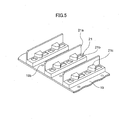
- Fig. 5 is a perspective view of the crawler plates 21 provided around the outer crawler belt 19.
- the crawler plates 21 have substantially the same width as that of the outer crawler belt 19.
- Lags 21a extend in the vertical direction from one end of each of the base portions of the crawler plates 21 which are adjacent to the outer crawler belt 19.
- the lags 21a have substantially the same width as that of the crawler plates 21.
- the lags 21a have substantially the same height.
- the lags 21a are for definitely engaging the crawler plates 21 with the ground, and thus the shape of the lags 21a is not limited as long as the lags 21a engage with the ground.
- the crawler plates 21 have recesses 21b at their respective base portions. The recesses 21b are for preventing the crawler plates 21 from slipping.
- the recesses 21b may have any shape as long as the crawler plates 21 are prevented from slipping.
- the recesses 21b are optional.
- the crawler plates 21 have protrusions 21c.
- the protrusions 21c prevent the crawler plates 21 from slipping.
- the protrusions 21c have female screws (not shown) on their respective undersides so that the crawler plates 21 can be connected to the outer crawler belt 19 by the bolts 25.
- the protrusions 21c are optional.
- the outer crawler belt 19 may have sand holes 19b.
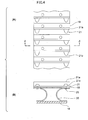
- Fig. 6 (A) is a plane view showing the engagement (engaging structure) between the sprocket 12 and the inner crawler belt 18 of a second embodiment of the present invention
- Fig. 6 (B) is a cross sectional view along A-A line of Fig. 6 (A).
- Fig. 6 (A)(B) is for showing the engagement between the sprocket 12 and the inner crawler belt 18, and thus the members such as the outer crawler belt 19 and the elastic members 20 are not shown.
- the inner crawler belt 18 engages the sprocket 12 not only at the center portion in the width direction of the inner crawler belt 18, but also at both ends of the inner crawler belt 18.
- the sprocket 12 has protrusions 12a at regular intervals at the center portion in the width direction of the inner crawler belt 18.
- the inner crawler belt 18 has holes 18b for inserting the protrusions 12a of the sprocket 12 at the same intervals as those for the protrusions 12a.
- the protrusions 12a of the sprocket 12 engage with the holes 18b of the inner crawler belt 18 to drive the inner crawler belt 18.
- the sprocket 12 does not have the ribs 12c of the same height, but instead has protrusions 12b at regular intervals at both ends in the width direction around the sprocket 12.
- the inner crawler belt 18 has recesses 18c for inserting the protrusions12b of the sprocket 12 at the same intervals as those for the protrusions12b.
- the protrusions 12a of the sprocket 12 engage the holes 18c of the inner crawler belt 18 to drive the inner crawler belt 18.
- the protrusions 12b of the sprocket 12 also hold the inner crawler belt 18 so that the inner crawler belt 18 will not deviate from the sprocket 12.
- Fig. 7 is a perspective view showing a portion of the crawler belt of a second embodiment.
- the inner crawler belt 18 has recesses 18c at both ends in the width direction of the inner crawler belt 18.
- the inner crawler belt 18 has two rows of holes 18b.
- the elastic members 20 are connected to the outer crawler belt 19 by bolts 25.
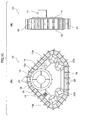
- Fig. 8 (A) is a side view of the crawler unit of the second embodiment showing that the side cover 16 covers the ends of the sprocket 12 and the idler wheels 13a,13b
- Fig. 8 (B) is a schematic cross sectional view.
- a brush 15 is shown in Fig. 8 (A) .
- the first embodiment has the same side cover 16 as that in the second embodiment.
- the side cover 16 is mounted to the holding member 17, and covers the ends of the sprocket 12 and the idler wheels 13a,13b.
- the end 16a of the side cover 16 extends to the recessed portions of the elastic members 20 between the inner crawler belt 18 and the outer crawler belt 19.
- This structure prevent stones and sand from entering into the engaging portions of the inner crawler belt 18 and the sprocket 12.
- the protrusions 12b of the sprocket 12 engage the recesses of the inner crawler belt 18.
- the idler wheels 13a,b have ribs 13c at both ends in the width direction of the idler wheels. The ribs 13c hold both ends of the inner crawler belt 18 so that the inner crawler belt 18 will not deviate from the idler wheels 13a,b.
- Fig. 9 (A) is a schematic perspective view of a portion of the crawler unit of a third embodiment showing a wire crawler belt 23 which is the outer crawler belt.
- the outer crawler belt has a plurality of wires parallel to the longitudinal direction of the outer crawler belt.
- Crawler plates 21 are mounted to the wire crawler belt 23 at regular intervals.
- the wire crawler belt 23 is more deformable than the outer crawler belt 19 of the embodiment shown in Fig. 1 , and thus more conformable to the shape of the ground surface.
- Fig. 9 (B) is a schematic perspective view showing a portion of a mesh crawler belt 24.
- the mesh crawler belt 24, in addition to the wires shown in Fig. 9 (A) has wires orthogonal to the wires shown in Fig. 9 (A) .
- the mesh crawler belt 24 has wires in the longitudinal direction and width direction thereof, and thus a stable performance is obtained.
- Fig. 10 (A) is a schematic side view of a fourth embodiment of the present invention showing a crawler unit 10'
- Fig. 10 (B) is a front view thereof.
- the crawler unit 10' is different from the crawler unit 10 of the first embodiment shown in Fig. 1 in that the crawler unit 10' has rotating wheels 22a, 22b in addition to the idler wheels 13a, 13b.
- the other members of the crawler unit 10' are the same as those of the crawler unit 10 shown in Fig. 1 . That is, the ribs 12c which have the same height are provided at the ends in the width direction of the sprocket 12. Because the crawler unit 10' has a lot of wheels which engage the crawler belt, the ground is contacted with more uniform pressure.
- Fig. 11 is a perspective view of an example of the crawler unit 10 of the first embodiment shown in Fig. 1 .
- the ribs 12c which have the same height are provided at the ends in the width direction around the sprocket 12.
- the cover 16 is not provided in this example.
- Fig. 12 is a photograph of an example of the crawler unit 10 of the first embodiment shown in Fig. 1 .
- This example has the sprocket and the idler wheels made of aluminum alloy (a diameter of about 140mm and thickness of about 3mm), the inner crawler belt 18 and the outer crawler belt 19 made of stainless steel (a thickness of 0.2mm and width of 65mm), the elastic members 20 made of stainless steel (a thickness of 0.2mm and width of 10mm) and the crawler plates made of aluminum alloy (10 ⁇ 10 ⁇ 1.5mm aluminum angle bar).
- the example shown in Fig. 12 has the elastic members 20 which are not orthogonal to the direction of the crawler belt but instead oblique to it.
- the crawler type vehicle having the crawler type traveling devices of the present invention contacts the ground with a uniform pressure, and has a simple structure suitable for use in space.
- the present invention can also be used as a crawler type vehicle for households.
Landscapes
- Engineering & Computer Science (AREA)
- Chemical & Material Sciences (AREA)
- Combustion & Propulsion (AREA)
- Transportation (AREA)
- Mechanical Engineering (AREA)
- Non-Deflectable Wheels, Steering Of Trailers, Or Other Steering (AREA)
- Handcart (AREA)
Abstract
Description
- The present invention relates to a traveling device for a crawler type vehicle. More specifically, the present invention relates to a crawler type traveling device for a space robot and a space exploration vehicle, and a crawler type vehicle comprising such crawler type traveling devices.
- The ground surfaces of a moon and planets are usually not stable ground. Instead, such ground surfaces are usually covered by sand, and thus have poor bearing power. Further, when a vehicle travels on the moon and planets on which the gravity is lower than that on earth, it is necessary to distribute the weight of the vehicle over a wide area, and to lower the pressure contacting the ground when traveling.
One type of prior art space exploration vehicle has four to eight cylindrical wheels for enabling wide a ground area to be contacted. In such vehicle having wheels, the pressure contacting the ground is at a maximum under the wheels. Thus, the wheels are likely to be buried under the sand, and it would be difficult to continue traveling. - One type of combat car or construction vehicle is a crawler type vehicle which comprises a driving wheel, idler wheels and a crawler belt spooled over the driving wheel and the idler wheel, and travels on the ground using the crawler belt. The crawler type vehicle contacts a wide area of ground, and thus has a good traveling capability even on a soft ground.
The crawler type traveling device comprises a crawler belt having a plurality of crawler plates made of a rigid metal, the crawler plates being pivotally connected to adjacent plates by pins. The crawler belt goes around the driving wheel and the idler wheels. Another crawler belt is made of a rubber having flexibility, and does not have crawler plates connected by pins.
Under a vacuum or low pressure atmosphere on the moon or planets, pin portions which connect the crawler plates have poor lubricity, and thus have much friction. Thus, durability is degraded.
The crawler belt made of rubber exhausts much gas out of the belt and is easily degraded, and thus it is not suitable to use in space. - Further, a crawler type vehicle needs a lot of rotating wheel mechanisms for equalizing the pressure contacting the ground. Thus this mechanism is complicated and heavy, and reliability is degraded thereby.
- Patent Document 1 (
JP 2005-111595
However, the crawler type traveling robot shown inpatent document 1 does not contact the ground with uniform pressure. Further, there is a possibility that stones or sand will easily enter into the engaging portions of the crawler belt and the driving wheel. - Patent Document 1:
JP 2005-111595 - An object of the present invention is to provide a crawler belt with no movable portion connected by pins etc., and thus to provide a crawler type traveling device which has no lubricating problem.
An object of the present invention is to provide a crawler type traveling device with few rotating wheel mechanisms which equalizes the pressure thereof contacting the ground.
Another object of the present invention is to provide a crawler type traveling device in which stones or sand will not easily enter into the engaging portions of the crawler belt and the driving wheel.
A further object of the present invention is to provide a crawler type vehicle having such crawler type traveling devices. - In the present invention, a crawler belt (assembly) comprises a double crawlers configuration having an outer crawler belt and an inner crawler belt. Each of the outer and inner crawler belts is made of a thin metal plate or resin plate having a ring shape and flexibility. The outer crawler belt and the inner crawler belt are connected by elastic members. The elastic members are deformable so that the outer crawler belt and the inner crawler belt can come near to each other and far away. Thus the outer crawler is deformable according to the conditions of the ground, and thus the ground is contacted with uniform pressure.
- One aspect of the present invention is a crawler type traveling device comprising:
- a driving wheel driven by a driving axis;
- idler wheels having axes parallel to that of the driving wheel; and a crawler belt which is spooled around the driving wheel and the idler wheels and travels around the driving wheel and the idler wheels;
wherein the crawler belt comprises:- an inner crawler belt having an engaging structure engaging with the driving wheel, the inner crawler belt being driven by the driving wheel;
- an outer crawler belt encircling circumferentially the outside of the inner crawler belt;
- a plurality of elastic members connecting the inner crawler belt and the outer crawler belt along the circumferential direction of the crawler belt; and
- a plurality of crawler plates mounted to the outer crawler belt, and having lag (lag constitution) for engaging with the ground.
- The crawler belt comprises a double crawler belts configuration including an outer crawler belt and an inner crawler belt, and the inner crawler belt engages with the driving wheel. Thus, the inner crawler belt is not likely to contact the ground surface, and thus stones or sand will not easily enter into the engaging portions between the crawler belt and the driving wheel.
The crawler belt itself has flexibility in the thickness direction thereof due to the elastic members. The outer crawler belt is deformable according to the shape of the ground and stones. Thus, the ground is contacted with uniform pressure and a high driving force is obtained. - Preferably, the inner crawler belt and the outer crawler belt are each made of a thin metal plate or resin plate having a ring shape and flexibility.
The crawler belt does not have a movable portion connected by a pin etc., and thus there is no lubricating problem. - Preferably, the elastic members connecting the inner crawler belt and the outer crawler belt are made of an elastic metal plate having a curved shape.
Because the crawler belt is made of metal, there is no gas exhausted out of the belt, and thus it is suitable for use in space. - Preferably, one end of each of the elastic members may be connected to the end in the width direction of the inner crawler belt, the other end of each of the elastic members is connected to the end in the width direction of the outer crawler belt, and the intermediate portion of each of the elastic members has a concaved shape bent toward the center portion in the width direction of the crawler belt.
Thus the crawler belt having good elasticity is obtained. - Preferably, the driving wheel has protrusions at regular intervals at its center portion in the width direction thereof, the inner crawler belt has recesses which engage with the protrusions at its center portion in the width direction thereof, and the driving wheel drives the inner crawler belt.
The protrusions and the recesses comprise an engaging structure.
Preferably, the driving wheel has protrusions at regular intervals at the ends in the width direction thereof, the inner crawler belt has recesses which engage with the protrusions at the ends in the width direction thereof, and the protrusions engage the recesses, and the driving wheel drives the inner crawler belt.
The crawler belt is thus driven more reliably. - Preferably, the outer crawler belt comprises a wire crawler belt made of a plurality of metal wires extending in the circumferential direction of the outer crawler belt, and a plurality of the crawler plates are connected to the wire crawler belt at regular intervals.
The wire crawler belt is more deformable, and thus more conformable to the shape of the ground surface.
Preferably, the outer crawler belt comprises a mesh crawler belt made of a metal mesh having wires extending in the circumferential direction and in the width direction of the outer crawler belt, and a plurality of the crawler plates are connected to the wire crawler belt at regular intervals.
The mesh crawler belt has a more stable performance than the wire crawler belt. - The crawler type traveling device may further comprises a side cover covering the sides of the driving wheel, the idle wheels and the inner crawler belt, the end of the side cover extending to the portion between the inner crawler belt and the outer crawler belt.
Stone and sand are thus prohibited from entering the engaging portions of the crawler type traveling device. - The crawler type traveling device may further comprise rotating wheels having axes parallel to that of the driving wheel; and the crawler belt which is spooled around the driving wheel, the idler wheels and the rotating wheels, and travels around the driving wheel, the idler wheels and the contact wheels.
Because there are a number of the wheels engaging the crawler belt, the ground surface is contacted with a more uniform pressure. - Another aspect of the present invention is a crawler type vehicle including crawler type traveling devices, each of the crawler type traveling device comprising:
- a driving wheel driven by a driving axis;
- idler wheels having axes parallel to that of the driving wheel; and
- a crawler belt which is spooled around the driving wheel and the idler wheels and travels around the driving wheel and the idler wheels;
- wherein the crawler belt comprises :
- an inner crawler belt having a engaging structure engaging with the driving wheel, the inner crawler belt being driven by the driving wheel;
- an outer crawler belt encircling circumferentially the outside of the inner crawler belt;
- a plurality of elastic members connecting the inner crawler belt and the outer crawler belt along the circumferential direction of the crawler belt; and
- a plurality of crawler plates mounted to the outer crawler belt, and having lag for engaging with the ground.
- In the present invention, the crawler belt comprises a double crawler belts configuration having an outer crawler belt and an inner crawler belt. The outer crawler belt contacts the ground surface, and the inner crawler belt engages to the driving wheel. Thus, the inner crawler belt is not likely to contact the ground surface, and thus stones or sand will not easily enter into the engaging portions of the inner crawler belt and the driving wheel.
The crawler belt itself has flexibility in the thickness direction thereof. Thus, the outer crawler belt is deformable according to the shape of the ground and stones. Thus, the pressure with which the ground is contacted can be low, and a high driving force is obtained. Thus, the crawler type device is not likely to be buried in the sand, and has a good traveling capability.
The crawler belt itself has flexibility due to the elastic members and pushes the outer crawler belt to the ground. Thus the number of the rotating wheels which push the crawler to the ground can be reduced. Therefore, the structure of the crawler type travelling device can be simplified, the weight can be reduced, and thus increased reliability can be obtained.
Further, the elastic members connecting the inner crawling wheel and the outer crawling wheel have a shape bending inwardly, and thus the side surface of the elastic members would not cause the ground to collapse.
Further, since the rotating wheels do not easily contact the ground or stones, the diameter of the rib of the rotating wheels for preventing the crawler belt from deviating is not limited to a small diameter. - According to the present invention, a crawler belt with no movable portions connected by pins etc. is provided, and thus a crawler type traveling device having no lubricating problem is provided.
A crawler type traveling device is provided having a small number of rotary mechanisms, and the ground is contacted with uniform pressure .
Further, a crawler type vehicle is provided having such crawler type traveling devices. - Now, embodiments of the present invention will be described. The embodiments relate to a crawler type traveling device for a space robot and a space exploration vehicle. However, the present invention is not limited to the crawler type vehicle for use in space. That is, the present invention can be used for crawler type vehicles for various household applications.
-
Fig. 1 (A) shows a schematic side view of acrawler unit 10 of a crawler type traveling device according to a first embodiment of the present invention, andFig. 1 (B) shows a front view thereof. In the description of the present invention, onecrawler unit 10 is referred to as a crawler type traveling device. - The crawler unit 10 (crawler type traveling device) comprises a
rotating driving axis 11 connected to an actuator (a driving source, not shown) such as a motor, and a cylindrical sprocket (a driving wheel) 12.Protrusions 12a are provided for engaging to a crawler wheel around thesprocket 12. Ribs which have a large diameter (flange) 12c are provided at the ends in the width direction of thesprocket 12 for holding the crawler belt.
In the prior art crawler mechanism, if the diameter of the ribs is too large, the ribs protrude out of the crawler belt, and thus the ribs are likely to contact the ground directly. Thus, the diameter of the ribs can not be too large. The crawler belt of the present invention has double crawler belts and is thick, and thus the diameter of the ribs can be large. - The
crawler unit 10 also comprises afront idler wheel 13a which has a cylindrical shape and arear idler wheel 13b which has a cylindrical shape.
The axis of thefront idler wheel 13a and the axis of therear idler wheel 13b are parallel to the axis of thesprocket 12.Ribs 13c which have a large diameter are provided at the ends in the width direction of theidler wheels
Thecrawler unit 10 comprises a holdingmember 17 for holding each member of thecrawler unit 10, the holdingmember 17 being the main structure of thecrawler unit 10. Thesprocket 12, thefront idler wheel 13a, therear idler wheel 13b and other members are mounted to the holdingmember 17. - A crawler belt is spooled around the
sprocket 12, thefront idler wheel 13a and therear idler wheel 13b. The crawler belt includes aninner crawler belt 18 for engaging thesprocket 12, thefront idler wheel 13a and therear idler wheel 13b. Theinner crawler belt 18 is made of a metal plate or a resin plate having a thin ring shape (short cylindrical shape), and is flexible, and thus can go around thesprocket 12 and theidler wheels 13a,b by following the outer shapes of thesprocket 12 and theidler wheels 13a,b. Theinner crawler belt 18 has holes for engaging theprotrusions 12a of thesprocket 12. Theprotrusions 12a of thesprocket 12 engage the holes of theinner crawler belt 18 to drive theinner crawler belt 18. - The
crawler unit 10 comprises anouter crawler belt 19 encircling circumferentially theinner crawler belt 18. Theouter crawler belt 19 is made of a metal plate or a resin plate having a thin ring shape, and is flexible. Theouter crawler belt 19 has a wider width than that of theinner crawler belt 18. Alternatively, theouter crawler belt 19 may have substantially the same width as that of theinner crawler belt 18.
Theinner crawler belt 18 is connected to theouter crawler belt 19 byelastic members 20. One end of each of theelastic members 20 is connected to an end in the width direction of theinner crawler belt 18, and the other end of each of theelastic members 20 is connected to an end in the width direction of theouter crawler belt 19. Each of the intermediate portions of theelastic members 20 is bent toward the center portion in the width direction of the crawler belt. Theelastic members 20 are made of elastic metal, and thus are easily deformable in the thickness direction of the crawler belt.
The crawler belt is integrally comprised of theinner crawler belt 18, theouter crawler belt 19 and theelastic members 20. The crawler belt has flexibility, and can go around thesprocket 12 and theidler wheels
Crawler plates 21 are provided around theouter crawler belt 19. The structures of thecrawler plates 21 will be explained later referring toFigs. 4 and5 . - Further, the
crawler unit 10 comprises atensioner 14. Thetensioner 14 presses theinner crawler belt 18 from the inside so that theinner crawler belt 18 will not bend inwardly.
Further, thecrawler unit 10 comprises abrush 15. Thebrush 15 engages theinner crawler belt 18 from the inside to brush out the stones and sand adhered to theinner crawler belt 18.
Further, thecrawler unit 10 comprises aside cover 16. (InFig. 1 (A) , theside cover 16 is shown in dashed lines so that inner members can be seen.) The side cover 16 covers the sides of thesprocket 12, the frontidle wheel 13a, the rearidle wheel 13b and theinner crawler belt 18 to preventing stones and sand entering into the engaging portions of the inner crawler belt and the sprocket. The shape of theside cover 16 will be explained referring toFig. 8 later. -
Fig. 2 is a schematic view of a crawler type vehicle having a pair of thecrawler units 10 at the right and left sides of thecar body 30. -
Fig. 3 is a schematic side view of a crawler type vehicle having a pair of thecrawler units 10 connected to a steering mechanism at a front portion of thecar body 30 and a pair of thecrawler units 10 at a rear portion of thecar body 30. Apivot hinge 34 is provided at the center portion in the longitudinal direction of thecar body 30, thepivot hinge 34 extending in the transverse direction of thecar body 30. Pivot beams 33 are mounted to thepivot hinge 34, the pivot beams 33 being substantially parallel to the sides of thecar body 30. The pivot beams 33 can be pivoted around thepivot hinge 34. While the crawler type vehicle is traveling, when thefront crawler unit 10 has a height different from that of the rearfront crawler unit 10, the crawler type vehicle can follow the shape of the ground.
Steering mechanisms 32 are provided at both ends of each of two pivot beams 33. Thesteering mechanism 32 can rotate thecrawler unit 10 around the axis in the vertical direction to turn thecrawler unit 10. Instead ,thesteering mechanism 32 can be provided at only one end of each of the two pivot beams 33. -
Fig. 4 (A) shows a schematic plane view of a portion of the crawler belt, andFig. 4 (B) is a cross sectional view along A-A line ofFig. 4 (A) . - The
outer crawler belt 19 encircles theinner crawler belt 18 which has a short cylindrical shape. Theinner crawler belt 18 is connected to theouter crawler belt 19 by a plurality of theelastic members 20. All around theinner crawler belt 18, theelastic members 20 are provided at regular intervals in the longitudinal direction of theinner crawler belt 18. Each of theelastic members 20 connects one end in the width direction of theinner crawler belt 18 to one end in the width direction of theouter crawler belt 19. Each of the intermediate portions of theelastic members 20 between theinner crawler belt 18 and theouter crawler belt 19 is bent toward the center portion in the width direction of the crawler belt. That is, theelastic members 20 has a curved shape. - The
elastic members 20 are made of metal such as a stainless steel having a thin thickness, and thus can be easily deformable. Thus the interval between theinner crawler belt 18 and theouter crawler belt 19 can be easily changed according to the shape of the ground, theouter crawler belt 19 following the shape of the ground.
Theelastic members 20 may have other shapes than that shown here so long as they are easily deformable. For example, each of theelastic members 20 may not be parallel to the width direction of theinner crawler belt 18, but instead may be oblique to the width direction of theinner crawler belt 18.
Crawler plates 21 are provided around theouter crawler belt 19 at regular intervals in the circumferential direction. Thecrawler plates 21 are made of a rigid metal. Thecrawler plates 21 engage the ground to obtain driving strength.
Theelastic members 20, theouter crawler belt 19 and thecrawler plates 21 are connected to each other bybolts 25. Each of thecrawler plates 21 is mounted to theouter crawler belt 19, thecrawler plates 21 not being connected to each other by pins. -
Fig. 5 is a perspective view of thecrawler plates 21 provided around theouter crawler belt 19. Thecrawler plates 21 have substantially the same width as that of theouter crawler belt 19.Lags 21a extend in the vertical direction from one end of each of the base portions of thecrawler plates 21 which are adjacent to theouter crawler belt 19. Thelags 21a have substantially the same width as that of thecrawler plates 21. Thelags 21a have substantially the same height. Thelags 21a are for definitely engaging thecrawler plates 21 with the ground, and thus the shape of thelags 21a is not limited as long as thelags 21a engage with the ground.
Thecrawler plates 21 haverecesses 21b at their respective base portions. Therecesses 21b are for preventing thecrawler plates 21 from slipping. Therecesses 21b may have any shape as long as thecrawler plates 21 are prevented from slipping. Therecesses 21b are optional.
Thecrawler plates 21 haveprotrusions 21c. Theprotrusions 21c prevent thecrawler plates 21 from slipping. Theprotrusions 21c have female screws (not shown) on their respective undersides so that thecrawler plates 21 can be connected to theouter crawler belt 19 by thebolts 25. Theprotrusions 21c are optional.
Theouter crawler belt 19 may havesand holes 19b. -
Fig. 6 (A) is a plane view showing the engagement (engaging structure) between thesprocket 12 and theinner crawler belt 18 of a second embodiment of the present invention, andFig. 6 (B) is a cross sectional view along A-A line ofFig. 6 (A). Fig. 6 (A)(B) is for showing the engagement between thesprocket 12 and theinner crawler belt 18, and thus the members such as theouter crawler belt 19 and theelastic members 20 are not shown. In the second embodiment, theinner crawler belt 18 engages thesprocket 12 not only at the center portion in the width direction of theinner crawler belt 18, but also at both ends of theinner crawler belt 18.
Thesprocket 12 hasprotrusions 12a at regular intervals at the center portion in the width direction of theinner crawler belt 18. Theinner crawler belt 18 hasholes 18b for inserting theprotrusions 12a of thesprocket 12 at the same intervals as those for theprotrusions 12a. Theprotrusions 12a of thesprocket 12 engage with theholes 18b of theinner crawler belt 18 to drive theinner crawler belt 18. - In the second embodiment, the
sprocket 12 does not have theribs 12c of the same height, but instead hasprotrusions 12b at regular intervals at both ends in the width direction around thesprocket 12. Theinner crawler belt 18 hasrecesses 18c for inserting the protrusions12b of thesprocket 12 at the same intervals as those for the protrusions12b. Theprotrusions 12a of thesprocket 12 engage theholes 18c of theinner crawler belt 18 to drive theinner crawler belt 18. Theprotrusions 12b of thesprocket 12 also hold theinner crawler belt 18 so that theinner crawler belt 18 will not deviate from thesprocket 12. -
Fig. 7 is a perspective view showing a portion of the crawler belt of a second embodiment. Theinner crawler belt 18 hasrecesses 18c at both ends in the width direction of theinner crawler belt 18. InFig. 7 , theinner crawler belt 18 has two rows ofholes 18b. Theelastic members 20 are connected to theouter crawler belt 19 bybolts 25. -
Fig. 8 (A) is a side view of the crawler unit of the second embodiment showing that theside cover 16 covers the ends of thesprocket 12 and theidler wheels Fig. 8 (B) is a schematic cross sectional view. Abrush 15 is shown inFig. 8 (A) . The first embodiment has thesame side cover 16 as that in the second embodiment. The side cover 16 is mounted to the holdingmember 17, and covers the ends of thesprocket 12 and theidler wheels end 16a of theside cover 16 extends to the recessed portions of theelastic members 20 between theinner crawler belt 18 and theouter crawler belt 19. This structure prevent stones and sand from entering into the engaging portions of theinner crawler belt 18 and thesprocket 12.
As shown in the schematic cross sectional view ofFig. 8 (B) , theprotrusions 12b of thesprocket 12 engage the recesses of theinner crawler belt 18. Theidler wheels 13a,b haveribs 13c at both ends in the width direction of the idler wheels. Theribs 13c hold both ends of theinner crawler belt 18 so that theinner crawler belt 18 will not deviate from theidler wheels 13a,b. -
Fig. 9 (A) is a schematic perspective view of a portion of the crawler unit of a third embodiment showing awire crawler belt 23 which is the outer crawler belt. The outer crawler belt has a plurality of wires parallel to the longitudinal direction of the outer crawler belt.Crawler plates 21 are mounted to thewire crawler belt 23 at regular intervals.
Thewire crawler belt 23 is more deformable than theouter crawler belt 19 of the embodiment shown inFig. 1 , and thus more conformable to the shape of the ground surface.
Fig. 9 (B) is a schematic perspective view showing a portion of amesh crawler belt 24.
Themesh crawler belt 24, in addition to the wires shown inFig. 9 (A) , has wires orthogonal to the wires shown inFig. 9 (A) . Themesh crawler belt 24 has wires in the longitudinal direction and width direction thereof, and thus a stable performance is obtained. -
Fig. 10 (A) is a schematic side view of a fourth embodiment of the present invention showing a crawler unit 10', andFig. 10 (B) is a front view thereof. The crawler unit 10' is different from thecrawler unit 10 of the first embodiment shown inFig. 1 in that the crawler unit 10' hasrotating wheels idler wheels crawler unit 10 shown inFig. 1 . That is, theribs 12c which have the same height are provided at the ends in the width direction of thesprocket 12. Because the crawler unit 10' has a lot of wheels which engage the crawler belt, the ground is contacted with more uniform pressure. -
Fig. 11 is a perspective view of an example of thecrawler unit 10 of the first embodiment shown inFig. 1 . Theribs 12c which have the same height are provided at the ends in the width direction around thesprocket 12. There are noprotrusions 12b of the second embodiment shown inFig. 6 . Thecover 16 is not provided in this example. -
Fig. 12 is a photograph of an example of thecrawler unit 10 of the first embodiment shown inFig. 1 . This example has the sprocket and the idler wheels made of aluminum alloy (a diameter of about 140mm and thickness of about 3mm), theinner crawler belt 18 and theouter crawler belt 19 made of stainless steel (a thickness of 0.2mm and width of 65mm), theelastic members 20 made of stainless steel (a thickness of 0.2mm and width of 10mm) and the crawler plates made of aluminum alloy (10×10×1.5mm aluminum angle bar). The example shown inFig. 12 has theelastic members 20 which are not orthogonal to the direction of the crawler belt but instead oblique to it. - The crawler type vehicle having the crawler type traveling devices of the present invention contacts the ground with a uniform pressure, and has a simple structure suitable for use in space. The present invention can also be used as a crawler type vehicle for households.
-
-
Fig. 1 (A) shows a schematic side view of acrawler unit 10 of a crawler type traveling device according to the first embodiment of the present invention (the cover is shown in dashed lines), andFig. 1 (B) shows a front view thereof. -
Fig. 2 is a schematic view of a crawler type vehicle having a pair of the crawler units at right and left sides of the body of the vehicle. -
Fig. 3 is a schematic side view of a crawler type vehicle having a pair of the crawler units connected to the steering mechanism at the front portion of the car body and a pair of the crawler units at the rear portion of the car body. -
Fig. 4 (A) is a schematic plane view of a portion of the crawler belt,Fig. 4 (B) is a cross sectional view along A-A line ofFig. 4 (A) . -
Fig. 5 is a perspective view of the crawler plates provided around the outer crawler belt. -
Fig. 6 (A) is a plane view showing the engagement between the sprocket and the inner crawler belt of the second embodiment, andFig. 6 (B) is a cross sectional view along A-A line of (A). -
Fig. 7 is a perspective view showing a portion of the crawler belt of the second embodiment. -
Fig. 8 (A) is a schematic side view showing the side cover, andFig. 8 (B) is a schematic cross sectional view of the second embodiment. -
Fig. 9 (A) is a schematic perspective view showing a portion of the wire crawler belt (the outer crawler belt) of the third embodiment, andFig. 9 (B) is a schematic perspective view of a portion of the mesh crawler belt. -
Fig. 10 (A) is a schematic side view showing a crawler unit of the fourth embodiment of the present invention, andFig. 10 (B) is a front view.
Fig. 11 is a perspective view of the example of the crawler unit of the first embodiment shown inFig. 1 .
Fig. 12 is a photograph of the example of the crawler unit of the first embodiment shown inFig. 1 . -
- 10
- crawler unit
- 11
- rotating driving axis
- 12
- sprocket (driving wheel)
- 12a, b
- protrusion
- 12c
- rib
- 13a
- front idler wheel
- 13b
- rear idler wheel
- 13c
- rib
- 14
- tensioner
- 15
- brush
- 16
- side cover
- 17
- holding member
- 18
- inner crawler belt
- 18b
- hole
- 18c
- recess
- 19
- outer crawler belt
- 19b
- sand hole
- 20
- elastic member
- 21
- crawler plate
- 21a
- lag
- 21 b
- recess
- 21c
- protrusion
- 22
- rotating wheel
- 23
- wire crawler belt
- 24
- mesh crawler belt
- 25
- bolt
- 30
- car body
- 31
- traveling device
- 32
- steering mechanism
- 33
- pivot beams
- 34
- pivot hinge
- 35
- car body
Claims (11)
- A crawler type traveling device comprising:a driving wheel driven by a driving axis;idler wheels having axes parallel to that of the driving wheel; anda crawler belt which is spooled around the driving wheel and the idler wheels and travels around the driving wheel and the idler wheels;wherein the crawler belt comprising :an inner crawler belt having a engaging structure engaging with the driving wheel, the inner crawler belt being driven by the driving wheel;an outer crawler belt encircling circumferentially the outside of the inner crawler belt;a plurality of elastic members connecting the inner crawler belt and the outer crawler belt along the circumferential direction of the crawler belt; anda plurality of crawler plates mounted to the outer crawler belt, and having lag for engaging with the ground.
- The crawler type traveling device according to claim 1, wherein the inner crawler belt and the outer crawler belt are made of a thin metal plate or resin plate having a ring shape and flexibility.
- The crawler type traveling device according to claim 1, wherein the elastic members connecting the inner crawler belt and the outer crawler belt are made of a metal plate or resin plate which is elastic and has a curved shape.
- The crawler type traveling device according to claim 3, wherein one end of each of the elastic members is connected to the end in the width direction of the inner crawler belt, the other end of each of the elastic members is connected to the end in the width direction of the outer crawler belt, and the intermediate portion of each of the elastic members has a concaved shape bent toward the center portion
in the width direction of the crawler belt. - The crawler type traveling device according to claim 1, wherein the driving wheel has protrusions at regular intervals at the center portion in its width direction thereof, the inner crawler belt has recesses which engage with the protrusions at its center portion in the width direction thereof, and the driving wheel drives the inner crawler belt.
- The crawler type traveling device according to claim 5, wherein the driving wheel has protrusions at regular intervals at the ends in the width direction thereof, the inner crawler belt has recesses which engage with the protrusions at the ends in the width direction thereof, and the driving wheel driving the inner crawler belt.
- The crawler type traveling device according to claim 1, wherein the outer crawler belt comprises a wire crawler belt made of a plurality of metal wires extending in the circumferential direction of the outer crawler belt, and a plurality of the crawler plates are connected to the wire crawler belt at regular intervals.
- The crawler type traveling device according to claim 1, wherein the outer crawler belt comprises a mesh crawler belt made of a metal mesh having wires extending in the circumferential direction and in the width direction of the outer crawler belt, and a plurality of the crawler plates are connected to the wire crawler belt at regular intervals.
- The crawler type traveling device according to claim 1, further comprising a side cover covering the sides of the driving wheel, the idle wheels and the inner crawler belt, the end of the side cover extending to the portion between the inner crawler belt and the outer crawler belt.
- The crawler type traveling device according to claim 1, further comprising rotating wheels having axes parallel to that of the driving wheel; and the crawler belt which is spooled around the driving wheel, the idler wheels and the rotating wheels, and travels around the driving wheel, the idler wheels and the rotating wheels.
- A crawler type vehicle including crawler type traveling devices, each of the crawler type traveling devices comprising:a driving wheel driven by a driving axis;idler wheels having axes parallel to that of the driving wheel; anda crawler belt which is spooled around the driving wheel and the idler wheels and travels around the driving wheel and the idler wheels;wherein the crawler belt comprises :an inner crawler belt having an engaging structure engaging with the driving wheel, the inner crawler belt being driven by the driving wheel;an outer crawler belt encircling circumferentially the outside of the inner crawler belt;a plurality of elastic members connecting the inner crawler belt and the outer crawler belt along the circumferential direction of the crawler belt; anda plurality of crawler plates mounted to the outer crawler belt, and having a lag for engaging with the ground.
Applications Claiming Priority (2)
| Application Number | Priority Date | Filing Date | Title |
|---|---|---|---|
| JP2007334752A JP5261761B2 (en) | 2007-12-26 | 2007-12-26 | Crawler type traveling device |
| PCT/JP2008/073385 WO2009081923A1 (en) | 2007-12-26 | 2008-12-24 | Crawler type travel device |
Publications (3)
| Publication Number | Publication Date |
|---|---|
| EP2226239A1 true EP2226239A1 (en) | 2010-09-08 |
| EP2226239A4 EP2226239A4 (en) | 2011-06-01 |
| EP2226239B1 EP2226239B1 (en) | 2013-10-23 |
Family
ID=40801223
Family Applications (1)
| Application Number | Title | Priority Date | Filing Date |
|---|---|---|---|
| EP08863612.1A Not-in-force EP2226239B1 (en) | 2007-12-26 | 2008-12-24 | Crawler type travel device |
Country Status (6)
| Country | Link |
|---|---|
| US (1) | US8657043B2 (en) |
| EP (1) | EP2226239B1 (en) |
| JP (1) | JP5261761B2 (en) |
| CN (1) | CN101959748B (en) |
| CA (1) | CA2710609C (en) |
| WO (1) | WO2009081923A1 (en) |
Families Citing this family (11)
| Publication number | Priority date | Publication date | Assignee | Title |
|---|---|---|---|---|
| JP5331769B2 (en) * | 2010-09-16 | 2013-10-30 | トピー工業株式会社 | Crawler device and crawler robot |
| CN102114877A (en) * | 2011-01-30 | 2011-07-06 | 黄达峰 | Wheelless walking method and device for vehicles |
| KR102003068B1 (en) * | 2012-12-26 | 2019-07-23 | 두산인프라코어 주식회사 | Sprocket for excavator |
| KR101393595B1 (en) * | 2013-02-05 | 2014-05-12 | 현대중공업 주식회사 | Excavator having variable independent type crawler |
| CN103646139B (en) * | 2013-12-03 | 2016-09-21 | 中国船舶重工集团公司第七一六研究所 | Endless-track vehicle Six-degree-of-freedom Simulation method |
| KR101592947B1 (en) * | 2014-06-12 | 2016-02-11 | (주)제타크리젠 | Using Caterpillar wheel structure |
| DE102016203381B3 (en) * | 2016-03-02 | 2017-01-26 | Kässbohrer Geländefahrzeug AG | Screen belt system for a beach cleaning vehicle and beach cleaning vehicle |
| FR3066171B1 (en) * | 2017-05-15 | 2020-05-15 | Nexter Systems | TRACK FOR EQUIPPING A VEHICLE |
| CN110682971A (en) * | 2019-11-12 | 2020-01-14 | 无锡斯蒂姆教育科技有限公司 | Crawler Exploration Robot |
| JP7007694B1 (en) * | 2020-09-29 | 2022-01-25 | 矢崎化工株式会社 | Crawler unit and transport trolley for rough roads using it |
| JP2024071841A (en) * | 2022-11-15 | 2024-05-27 | ナカバヤシ株式会社 | Vehicle transport crawler and vehicle equipped with said crawler |
Family Cites Families (17)
| Publication number | Priority date | Publication date | Assignee | Title |
|---|---|---|---|---|
| US2899242A (en) * | 1959-08-11 | Bombardier | ||
| GB721141A (en) * | 1952-04-16 | 1954-12-29 | James Archibald Cuthbertson | Improvements relating to endless tracks for tractors and other vehicles |
| US3498684A (en) | 1967-06-28 | 1970-03-03 | Goodrich Co B F | Traction belt |
| US3495883A (en) * | 1967-12-01 | 1970-02-17 | Jacob Fischbach | Track and tracked vehicle |
| US3682266A (en) * | 1970-01-21 | 1972-08-08 | Tri Lok Inc | Track laying traction unit for replacing a road vehicle driving wheel |
| US3967721A (en) * | 1974-07-08 | 1976-07-06 | Fmc Corporation | Belt drive conveyor system |
| US4056288A (en) * | 1976-03-01 | 1977-11-01 | Caterpillar Tractor Co. | Endless track for crawler vehicles |
| FI68573C (en) | 1983-10-19 | 1985-10-10 | Fredrik Kullervo Burmeister | PNEUMATIC LARVMADRASS-SYSTEM FOER FORDON |
| JPH0811550B2 (en) | 1985-11-15 | 1996-02-07 | アルトラック リミテッド | Tracks for vehicles with tracks |
| JPS62214067A (en) * | 1986-03-13 | 1987-09-19 | Morooka:Kk | Net crawler |
| US5894901A (en) * | 1995-12-12 | 1999-04-20 | Babcock-Hitachi Kabushiki Kaisha | Endless track magnetic traveling device |
| JP2002006950A (en) * | 2000-06-21 | 2002-01-11 | Babcock Hitachi Kk | Traveling device |
| HUP0402314A2 (en) | 2001-10-03 | 2008-07-28 | Galileo Mobility Instr Ltd | Adaptable traction system of a vehicle |
| US7597161B2 (en) * | 2003-01-21 | 2009-10-06 | Glen Brazier | Terrain conforming track assembly |
| JP4607442B2 (en) * | 2003-10-07 | 2011-01-05 | 国立大学法人東京工業大学 | Crawler type traveling robot |
| JP4521523B2 (en) * | 2005-02-09 | 2010-08-11 | 独立行政法人 宇宙航空研究開発機構 | Tracked vehicle |
| JP4093318B2 (en) * | 2006-03-10 | 2008-06-04 | 横浜ゴム株式会社 | Non-pneumatic tire and manufacturing method thereof |
-
2007
- 2007-12-26 JP JP2007334752A patent/JP5261761B2/en not_active Expired - Fee Related
-
2008
- 2008-12-24 CN CN2008801275061A patent/CN101959748B/en not_active Expired - Fee Related
- 2008-12-24 US US12/810,509 patent/US8657043B2/en not_active Expired - Fee Related
- 2008-12-24 WO PCT/JP2008/073385 patent/WO2009081923A1/en not_active Ceased
- 2008-12-24 CA CA2710609A patent/CA2710609C/en active Active
- 2008-12-24 EP EP08863612.1A patent/EP2226239B1/en not_active Not-in-force
Also Published As
| Publication number | Publication date |
|---|---|
| CA2710609C (en) | 2017-10-24 |
| US20100282526A1 (en) | 2010-11-11 |
| JP2009154695A (en) | 2009-07-16 |
| US8657043B2 (en) | 2014-02-25 |
| WO2009081923A1 (en) | 2009-07-02 |
| CN101959748A (en) | 2011-01-26 |
| EP2226239A4 (en) | 2011-06-01 |
| CN101959748B (en) | 2012-10-10 |
| JP5261761B2 (en) | 2013-08-14 |
| CA2710609A1 (en) | 2009-07-02 |
| EP2226239B1 (en) | 2013-10-23 |
Similar Documents
| Publication | Publication Date | Title |
|---|---|---|
| EP2226239B1 (en) | Crawler type travel device | |
| EP2617631B1 (en) | Crawler device and crawler robot | |
| US8162410B2 (en) | Endless elongated member for crawler and crawler unit | |
| CN103974877B (en) | Chain link and crawler device for crawler belt | |
| CA2182459C (en) | Positive drive rubber track | |
| US9446805B2 (en) | Track assembly having arcuate crawler shoes | |
| EP1985528A1 (en) | Coreless rubber crawler and traveling device | |
| CN107848585B (en) | Caterpillars and traveling equipment | |
| KR101756817B1 (en) | Magnetic track for wall and ceiling traveling of steel structures | |
| JP5606878B2 (en) | Wheel for running | |
| RU2760164C2 (en) | Drive wheel and drive system for caterpillar vehicle | |
| JP2006111253A (en) | Under carriage equipped with a non-steel type rubber crawler using chain action | |
| US8398181B2 (en) | Endless elastomeric track | |
| JP5684493B2 (en) | Traveling device and robot | |
| JP2006151331A (en) | Crawler type traveling device | |
| KR101792670B1 (en) | Caterpillar driving apparatus using wire rope | |
| KR101739706B1 (en) | Apparatus of protecting cable | |
| JP2009214612A (en) | Wheel for celestial-body traveling vehicle | |
| EP3173318B1 (en) | Crawler device | |
| CN115667060B (en) | Tracked unit and differential terrain transport trolley using the tracked unit | |
| JPH09226642A (en) | Lower part structure for belt-type or crawler type machine | |
| WO2017017958A1 (en) | Elastic crawler | |
| KR101878583B1 (en) | Elastic crawler and crawler travelling device equipped with same | |
| JP2009121643A (en) | Power transmission chain and power transmission device | |
| JP2007255621A (en) | Power transmission chain and power transmission device |
Legal Events
| Date | Code | Title | Description |
|---|---|---|---|
| PUAI | Public reference made under article 153(3) epc to a published international application that has entered the european phase |
Free format text: ORIGINAL CODE: 0009012 |
|
| 17P | Request for examination filed |
Effective date: 20100624 |
|
| AK | Designated contracting states |
Kind code of ref document: A1 Designated state(s): AT BE BG CH CY CZ DE DK EE ES FI FR GB GR HR HU IE IS IT LI LT LU LV MC MT NL NO PL PT RO SE SI SK TR |
|
| AX | Request for extension of the european patent |
Extension state: AL BA MK RS |
|
| DAX | Request for extension of the european patent (deleted) | ||
| A4 | Supplementary search report drawn up and despatched |
Effective date: 20110504 |
|
| GRAP | Despatch of communication of intention to grant a patent |
Free format text: ORIGINAL CODE: EPIDOSNIGR1 |
|
| INTG | Intention to grant announced |
Effective date: 20130624 |
|
| GRAS | Grant fee paid |
Free format text: ORIGINAL CODE: EPIDOSNIGR3 |
|
| GRAA | (expected) grant |
Free format text: ORIGINAL CODE: 0009210 |
|
| AK | Designated contracting states |
Kind code of ref document: B1 Designated state(s): AT BE BG CH CY CZ DE DK EE ES FI FR GB GR HR HU IE IS IT LI LT LU LV MC MT NL NO PL PT RO SE SI SK TR |
|
| REG | Reference to a national code |
Ref country code: GB Ref legal event code: FG4D |
|
| REG | Reference to a national code |
Ref country code: CH Ref legal event code: EP |
|
| REG | Reference to a national code |
Ref country code: AT Ref legal event code: REF Ref document number: 637402 Country of ref document: AT Kind code of ref document: T Effective date: 20131115 |
|
| REG | Reference to a national code |
Ref country code: IE Ref legal event code: FG4D |
|
| REG | Reference to a national code |
Ref country code: DE Ref legal event code: R096 Ref document number: 602008028370 Country of ref document: DE Effective date: 20131219 |
|
| REG | Reference to a national code |
Ref country code: NL Ref legal event code: VDEP Effective date: 20131023 |
|
| REG | Reference to a national code |
Ref country code: AT Ref legal event code: MK05 Ref document number: 637402 Country of ref document: AT Kind code of ref document: T Effective date: 20131023 |
|
| REG | Reference to a national code |
Ref country code: LT Ref legal event code: MG4D |
|
| PG25 | Lapsed in a contracting state [announced via postgrant information from national office to epo] |
Ref country code: FI Free format text: LAPSE BECAUSE OF FAILURE TO SUBMIT A TRANSLATION OF THE DESCRIPTION OR TO PAY THE FEE WITHIN THE PRESCRIBED TIME-LIMIT Effective date: 20131023 Ref country code: SE Free format text: LAPSE BECAUSE OF FAILURE TO SUBMIT A TRANSLATION OF THE DESCRIPTION OR TO PAY THE FEE WITHIN THE PRESCRIBED TIME-LIMIT Effective date: 20131023 Ref country code: NL Free format text: LAPSE BECAUSE OF FAILURE TO SUBMIT A TRANSLATION OF THE DESCRIPTION OR TO PAY THE FEE WITHIN THE PRESCRIBED TIME-LIMIT Effective date: 20131023 Ref country code: NO Free format text: LAPSE BECAUSE OF FAILURE TO SUBMIT A TRANSLATION OF THE DESCRIPTION OR TO PAY THE FEE WITHIN THE PRESCRIBED TIME-LIMIT Effective date: 20140123 Ref country code: IS Free format text: LAPSE BECAUSE OF FAILURE TO SUBMIT A TRANSLATION OF THE DESCRIPTION OR TO PAY THE FEE WITHIN THE PRESCRIBED TIME-LIMIT Effective date: 20140223 Ref country code: BE Free format text: LAPSE BECAUSE OF FAILURE TO SUBMIT A TRANSLATION OF THE DESCRIPTION OR TO PAY THE FEE WITHIN THE PRESCRIBED TIME-LIMIT Effective date: 20131023 Ref country code: LT Free format text: LAPSE BECAUSE OF FAILURE TO SUBMIT A TRANSLATION OF THE DESCRIPTION OR TO PAY THE FEE WITHIN THE PRESCRIBED TIME-LIMIT Effective date: 20131023 Ref country code: HR Free format text: LAPSE BECAUSE OF FAILURE TO SUBMIT A TRANSLATION OF THE DESCRIPTION OR TO PAY THE FEE WITHIN THE PRESCRIBED TIME-LIMIT Effective date: 20131023 |
|
| PG25 | Lapsed in a contracting state [announced via postgrant information from national office to epo] |
Ref country code: CY Free format text: LAPSE BECAUSE OF FAILURE TO SUBMIT A TRANSLATION OF THE DESCRIPTION OR TO PAY THE FEE WITHIN THE PRESCRIBED TIME-LIMIT Effective date: 20131023 Ref country code: AT Free format text: LAPSE BECAUSE OF FAILURE TO SUBMIT A TRANSLATION OF THE DESCRIPTION OR TO PAY THE FEE WITHIN THE PRESCRIBED TIME-LIMIT Effective date: 20131023 Ref country code: ES Free format text: LAPSE BECAUSE OF FAILURE TO SUBMIT A TRANSLATION OF THE DESCRIPTION OR TO PAY THE FEE WITHIN THE PRESCRIBED TIME-LIMIT Effective date: 20131023 Ref country code: LV Free format text: LAPSE BECAUSE OF FAILURE TO SUBMIT A TRANSLATION OF THE DESCRIPTION OR TO PAY THE FEE WITHIN THE PRESCRIBED TIME-LIMIT Effective date: 20131023 |
|
| PG25 | Lapsed in a contracting state [announced via postgrant information from national office to epo] |
Ref country code: PT Free format text: LAPSE BECAUSE OF FAILURE TO SUBMIT A TRANSLATION OF THE DESCRIPTION OR TO PAY THE FEE WITHIN THE PRESCRIBED TIME-LIMIT Effective date: 20140224 |
|
| REG | Reference to a national code |
Ref country code: DE Ref legal event code: R097 Ref document number: 602008028370 Country of ref document: DE |
|
| PG25 | Lapsed in a contracting state [announced via postgrant information from national office to epo] |
Ref country code: EE Free format text: LAPSE BECAUSE OF FAILURE TO SUBMIT A TRANSLATION OF THE DESCRIPTION OR TO PAY THE FEE WITHIN THE PRESCRIBED TIME-LIMIT Effective date: 20131023 |
|
| REG | Reference to a national code |
Ref country code: CH Ref legal event code: PL |
|
| PG25 | Lapsed in a contracting state [announced via postgrant information from national office to epo] |
Ref country code: MC Free format text: LAPSE BECAUSE OF FAILURE TO SUBMIT A TRANSLATION OF THE DESCRIPTION OR TO PAY THE FEE WITHIN THE PRESCRIBED TIME-LIMIT Effective date: 20131023 Ref country code: RO Free format text: LAPSE BECAUSE OF FAILURE TO SUBMIT A TRANSLATION OF THE DESCRIPTION OR TO PAY THE FEE WITHIN THE PRESCRIBED TIME-LIMIT Effective date: 20131023 Ref country code: LU Free format text: LAPSE BECAUSE OF FAILURE TO SUBMIT A TRANSLATION OF THE DESCRIPTION OR TO PAY THE FEE WITHIN THE PRESCRIBED TIME-LIMIT Effective date: 20131224 Ref country code: IT Free format text: LAPSE BECAUSE OF FAILURE TO SUBMIT A TRANSLATION OF THE DESCRIPTION OR TO PAY THE FEE WITHIN THE PRESCRIBED TIME-LIMIT Effective date: 20131023 Ref country code: CZ Free format text: LAPSE BECAUSE OF FAILURE TO SUBMIT A TRANSLATION OF THE DESCRIPTION OR TO PAY THE FEE WITHIN THE PRESCRIBED TIME-LIMIT Effective date: 20131023 Ref country code: PL Free format text: LAPSE BECAUSE OF FAILURE TO SUBMIT A TRANSLATION OF THE DESCRIPTION OR TO PAY THE FEE WITHIN THE PRESCRIBED TIME-LIMIT Effective date: 20131023 Ref country code: SK Free format text: LAPSE BECAUSE OF FAILURE TO SUBMIT A TRANSLATION OF THE DESCRIPTION OR TO PAY THE FEE WITHIN THE PRESCRIBED TIME-LIMIT Effective date: 20131023 |
|
| PLBE | No opposition filed within time limit |
Free format text: ORIGINAL CODE: 0009261 |
|
| STAA | Information on the status of an ep patent application or granted ep patent |
Free format text: STATUS: NO OPPOSITION FILED WITHIN TIME LIMIT |
|
| GBPC | Gb: european patent ceased through non-payment of renewal fee |
Effective date: 20140123 |
|
| REG | Reference to a national code |
Ref country code: IE Ref legal event code: MM4A |
|
| REG | Reference to a national code |
Ref country code: FR Ref legal event code: ST Effective date: 20140829 |
|
| PG25 | Lapsed in a contracting state [announced via postgrant information from national office to epo] |
Ref country code: DK Free format text: LAPSE BECAUSE OF FAILURE TO SUBMIT A TRANSLATION OF THE DESCRIPTION OR TO PAY THE FEE WITHIN THE PRESCRIBED TIME-LIMIT Effective date: 20131023 |
|
| 26N | No opposition filed |
Effective date: 20140724 |
|
| PG25 | Lapsed in a contracting state [announced via postgrant information from national office to epo] |
Ref country code: CH Free format text: LAPSE BECAUSE OF NON-PAYMENT OF DUE FEES Effective date: 20131231 Ref country code: IE Free format text: LAPSE BECAUSE OF NON-PAYMENT OF DUE FEES Effective date: 20131224 Ref country code: LI Free format text: LAPSE BECAUSE OF NON-PAYMENT OF DUE FEES Effective date: 20131231 |
|
| REG | Reference to a national code |
Ref country code: DE Ref legal event code: R097 Ref document number: 602008028370 Country of ref document: DE Effective date: 20140724 |
|
| PG25 | Lapsed in a contracting state [announced via postgrant information from national office to epo] |
Ref country code: FR Free format text: LAPSE BECAUSE OF NON-PAYMENT OF DUE FEES Effective date: 20131231 Ref country code: GB Free format text: LAPSE BECAUSE OF NON-PAYMENT OF DUE FEES Effective date: 20140123 |
|
| PG25 | Lapsed in a contracting state [announced via postgrant information from national office to epo] |
Ref country code: SI Free format text: LAPSE BECAUSE OF FAILURE TO SUBMIT A TRANSLATION OF THE DESCRIPTION OR TO PAY THE FEE WITHIN THE PRESCRIBED TIME-LIMIT Effective date: 20131023 |
|
| PG25 | Lapsed in a contracting state [announced via postgrant information from national office to epo] |
Ref country code: TR Free format text: LAPSE BECAUSE OF FAILURE TO SUBMIT A TRANSLATION OF THE DESCRIPTION OR TO PAY THE FEE WITHIN THE PRESCRIBED TIME-LIMIT Effective date: 20131023 |
|
| PG25 | Lapsed in a contracting state [announced via postgrant information from national office to epo] |
Ref country code: HU Free format text: LAPSE BECAUSE OF FAILURE TO SUBMIT A TRANSLATION OF THE DESCRIPTION OR TO PAY THE FEE WITHIN THE PRESCRIBED TIME-LIMIT; INVALID AB INITIO Effective date: 20081224 Ref country code: BG Free format text: LAPSE BECAUSE OF FAILURE TO SUBMIT A TRANSLATION OF THE DESCRIPTION OR TO PAY THE FEE WITHIN THE PRESCRIBED TIME-LIMIT Effective date: 20131023 |
|
| PG25 | Lapsed in a contracting state [announced via postgrant information from national office to epo] |
Ref country code: MT Free format text: LAPSE BECAUSE OF FAILURE TO SUBMIT A TRANSLATION OF THE DESCRIPTION OR TO PAY THE FEE WITHIN THE PRESCRIBED TIME-LIMIT Effective date: 20131023 Ref country code: GR Free format text: LAPSE BECAUSE OF NON-PAYMENT OF DUE FEES Effective date: 20131023 |
|
| PG25 | Lapsed in a contracting state [announced via postgrant information from national office to epo] |
Ref country code: GR Free format text: LAPSE BECAUSE OF FAILURE TO SUBMIT A TRANSLATION OF THE DESCRIPTION OR TO PAY THE FEE WITHIN THE PRESCRIBED TIME-LIMIT Effective date: 20140124 |
|
| PGFP | Annual fee paid to national office [announced via postgrant information from national office to epo] |
Ref country code: DE Payment date: 20211210 Year of fee payment: 14 |
|
| REG | Reference to a national code |
Ref country code: DE Ref legal event code: R119 Ref document number: 602008028370 Country of ref document: DE |
|
| PG25 | Lapsed in a contracting state [announced via postgrant information from national office to epo] |
Ref country code: DE Free format text: LAPSE BECAUSE OF NON-PAYMENT OF DUE FEES Effective date: 20230701 |