EP2226222A1 - Air bag device and gas generator used therein - Google Patents
Air bag device and gas generator used therein Download PDFInfo
- Publication number
- EP2226222A1 EP2226222A1 EP10002334A EP10002334A EP2226222A1 EP 2226222 A1 EP2226222 A1 EP 2226222A1 EP 10002334 A EP10002334 A EP 10002334A EP 10002334 A EP10002334 A EP 10002334A EP 2226222 A1 EP2226222 A1 EP 2226222A1
- Authority
- EP
- European Patent Office
- Prior art keywords
- gas
- ignition agent
- agent
- ignition
- gas generator
- Prior art date
- Legal status (The legal status is an assumption and is not a legal conclusion. Google has not performed a legal analysis and makes no representation as to the accuracy of the status listed.)
- Granted
Links
- 239000003795 chemical substances by application Substances 0.000 claims abstract description 82
- 238000002485 combustion reaction Methods 0.000 claims abstract description 14
- 239000003999 initiator Substances 0.000 claims abstract description 11
- 230000004913 activation Effects 0.000 abstract description 16
- 230000000052 comparative effect Effects 0.000 description 10
- 239000002826 coolant Substances 0.000 description 4
- 230000006378 damage Effects 0.000 description 4
- 230000007423 decrease Effects 0.000 description 3
- 230000002123 temporal effect Effects 0.000 description 3
- 238000005266 casting Methods 0.000 description 2
- 230000003111 delayed effect Effects 0.000 description 2
- 238000006073 displacement reaction Methods 0.000 description 2
- 238000005242 forging Methods 0.000 description 2
- 238000000034 method Methods 0.000 description 2
- 230000002093 peripheral effect Effects 0.000 description 2
- 238000003825 pressing Methods 0.000 description 2
- 230000000452 restraining effect Effects 0.000 description 2
- 229910001220 stainless steel Inorganic materials 0.000 description 2
- 239000010935 stainless steel Substances 0.000 description 2
- 208000027418 Wounds and injury Diseases 0.000 description 1
- XAGFODPZIPBFFR-UHFFFAOYSA-N aluminium Chemical compound [Al] XAGFODPZIPBFFR-UHFFFAOYSA-N 0.000 description 1
- 229910052782 aluminium Inorganic materials 0.000 description 1
- 230000037237 body shape Effects 0.000 description 1
- 239000002775 capsule Substances 0.000 description 1
- 238000005520 cutting process Methods 0.000 description 1
- 230000001934 delay Effects 0.000 description 1
- 238000013461 design Methods 0.000 description 1
- 230000000694 effects Effects 0.000 description 1
- 238000002474 experimental method Methods 0.000 description 1
- 208000014674 injury Diseases 0.000 description 1
- 238000005259 measurement Methods 0.000 description 1
- 238000012986 modification Methods 0.000 description 1
- 230000004048 modification Effects 0.000 description 1
- 238000012545 processing Methods 0.000 description 1
- 238000012360 testing method Methods 0.000 description 1
Images



Classifications
-
- B—PERFORMING OPERATIONS; TRANSPORTING
- B60—VEHICLES IN GENERAL
- B60R—VEHICLES, VEHICLE FITTINGS, OR VEHICLE PARTS, NOT OTHERWISE PROVIDED FOR
- B60R21/00—Arrangements or fittings on vehicles for protecting or preventing injuries to occupants or pedestrians in case of accidents or other traffic risks
- B60R21/02—Occupant safety arrangements or fittings, e.g. crash pads
- B60R21/16—Inflatable occupant restraints or confinements designed to inflate upon impact or impending impact, e.g. air bags
- B60R21/26—Inflatable occupant restraints or confinements designed to inflate upon impact or impending impact, e.g. air bags characterised by the inflation fluid source or means to control inflation fluid flow
- B60R21/264—Inflatable occupant restraints or confinements designed to inflate upon impact or impending impact, e.g. air bags characterised by the inflation fluid source or means to control inflation fluid flow using instantaneous generation of gas, e.g. pyrotechnic
- B60R21/2644—Inflatable occupant restraints or confinements designed to inflate upon impact or impending impact, e.g. air bags characterised by the inflation fluid source or means to control inflation fluid flow using instantaneous generation of gas, e.g. pyrotechnic using only solid reacting substances, e.g. pellets, powder
-
- B—PERFORMING OPERATIONS; TRANSPORTING
- B60—VEHICLES IN GENERAL
- B60R—VEHICLES, VEHICLE FITTINGS, OR VEHICLE PARTS, NOT OTHERWISE PROVIDED FOR
- B60R21/00—Arrangements or fittings on vehicles for protecting or preventing injuries to occupants or pedestrians in case of accidents or other traffic risks
- B60R21/02—Occupant safety arrangements or fittings, e.g. crash pads
- B60R21/16—Inflatable occupant restraints or confinements designed to inflate upon impact or impending impact, e.g. air bags
- B60R21/26—Inflatable occupant restraints or confinements designed to inflate upon impact or impending impact, e.g. air bags characterised by the inflation fluid source or means to control inflation fluid flow
- B60R21/263—Inflatable occupant restraints or confinements designed to inflate upon impact or impending impact, e.g. air bags characterised by the inflation fluid source or means to control inflation fluid flow using a variable source, e.g. plural stage or controlled output
- B60R2021/2633—Inflatable occupant restraints or confinements designed to inflate upon impact or impending impact, e.g. air bags characterised by the inflation fluid source or means to control inflation fluid flow using a variable source, e.g. plural stage or controlled output with a plurality of inflation levels
-
- B—PERFORMING OPERATIONS; TRANSPORTING
- B60—VEHICLES IN GENERAL
- B60R—VEHICLES, VEHICLE FITTINGS, OR VEHICLE PARTS, NOT OTHERWISE PROVIDED FOR
- B60R21/00—Arrangements or fittings on vehicles for protecting or preventing injuries to occupants or pedestrians in case of accidents or other traffic risks
- B60R21/02—Occupant safety arrangements or fittings, e.g. crash pads
- B60R21/16—Inflatable occupant restraints or confinements designed to inflate upon impact or impending impact, e.g. air bags
- B60R21/26—Inflatable occupant restraints or confinements designed to inflate upon impact or impending impact, e.g. air bags characterised by the inflation fluid source or means to control inflation fluid flow
- B60R21/264—Inflatable occupant restraints or confinements designed to inflate upon impact or impending impact, e.g. air bags characterised by the inflation fluid source or means to control inflation fluid flow using instantaneous generation of gas, e.g. pyrotechnic
- B60R21/2644—Inflatable occupant restraints or confinements designed to inflate upon impact or impending impact, e.g. air bags characterised by the inflation fluid source or means to control inflation fluid flow using instantaneous generation of gas, e.g. pyrotechnic using only solid reacting substances, e.g. pellets, powder
- B60R2021/2648—Inflatable occupant restraints or confinements designed to inflate upon impact or impending impact, e.g. air bags characterised by the inflation fluid source or means to control inflation fluid flow using instantaneous generation of gas, e.g. pyrotechnic using only solid reacting substances, e.g. pellets, powder comprising a plurality of combustion chambers or sub-chambers
Definitions
- the present invention relates to an airbag device and a gas generator installed in a vehicle, and more particularly to an improvement in a gas generator for an airbag device having a featured activation performance.
- Vehicles such as automobiles are installed with an airbag system that prevents serious injury or death occurring when an occupant crashes into a hard part in the interior of the vehicle, such as a steering wheel or a front windshield, during a collision or the like by rapidly inflating a bag with gas so that the occupant is prevented from crashing into dangerous locations.
- an airbag system that prevents serious injury or death occurring when an occupant crashes into a hard part in the interior of the vehicle, such as a steering wheel or a front windshield, during a collision or the like by rapidly inflating a bag with gas so that the occupant is prevented from crashing into dangerous locations.
- An airbag system is preferably capable of restraining the occupant safely regardless of the body shape (for example, a sitting height and so on) of the occupant, the attitude of the occupant (for example, when the occupant is clinging to the steering wheel), and so on.
- airbag systems that are activated such that minimal impact is applied to the occupant during an initial activation stage have been proposed in the related art.
- gas is generated in two stages such that the airbag is inflated comparatively slowly in the first stage. In the second stage, gas is generated rapidly.
- two types of gas generating agent capsules are used. As a result, however, the internal structure of the gas generator becomes complicated and the size of a container increases, leading to an increase in cost.
- U.S. Patent No. 4, 998, 751 and U.S. Patent No. 4, 950, 458 similarly propose that an activation function of the gas generator be restricted by providing two combustion chambers such that the gas generating agent is burned in two stages.
- an activation function of the gas generator be restricted by providing two combustion chambers such that the gas generating agent is burned in two stages.
- a similar increase in structural complexity occurs in this case, and therefore these proposals cannot be considered satisfactory.
- Japanese Patent Application Publication No. H11-334517 discloses a structure for reducing an impact force of the airbag during the initial activation stage by providing a gap in a space housing the gas generating agent. As a result, however, it is difficult to obtain the initially required amount of gas, and therefore an occupant restraining performance may deteriorate.
- the present invention has been designed in consideration of the conditions described above, and an object thereof is to provide an airbag device and a gas generator used therein with which damage to an airbag module and an impact on an occupant can be reduced during an initial activation stage and the occupant can be restrained reliably while maintaining structural simplicity.
- a gas generator for an airbag device includes: an initiator (igniter) that is activated by an impact on the vehicle; an ignition agent that is ignited by the initiator; an ignition agent housing chamber housing the ignition agent; a gas generating agent that is.ignited and burned by the ignition agent; and a combustion chamber housing the gas generating agent.
- An airbag is inflated by a gas generated through combustion of the gas generating agent. Further, a space into which the ignition agent is not charged is formed in the ignition agent housing chamber.
- An airbag device includes, in addition to the gas generator described above, an airbag that is inflated and deployed by a gas generated by the gas generator.
- the ignition agent preferably occupies 30% to 50% of an interior volume of the ignition agent housing chamber such that the remainder constitutes the space.
- activation can be performed such that minimal impact is applied to the occupant during the initial activation stage and the occupant can be restrained reliably while maintaining structural simplicity.
- FIG. 1 is a schematic sectional view showing the structure of a gas generator for an airbag device according to an embodiment of the present invention.
- a gas generator 10 for an airbag device according to this embodiment includes an initiator (igniter) 14 that is activated by an impact on a vehicle, an ignition agent 22 that is ignited by the initiator 14, an ignition agent housing chamber 16 housing the ignition agent 22, a gas generating agent 24 that is ignited and burned by the ignition agent 22, and a combustion chamber 18 housing the gas generating agent 24.
- an initiator ignition
- ignition agent 22 that is ignited by the initiator 14
- an ignition agent housing chamber 16 housing the ignition agent 22
- a gas generating agent 24 that is ignited and burned by the ignition agent 22
- a combustion chamber 18 housing the gas generating agent 24.
- the gas generator 10 is structured to inflate an airbag using gas generated when the gas generating agent 24 is burned.
- a feature of this embodiment is that a space in which the ignition agent 22 is not charged is formed in the interior of the ignition agent housing chamber 16.
- the ignition agent 22 is preferably charged to approximately 30% to 50% of the interior volume of the ignition agent housing chamber 16 so that the remainder forms the space.
- a state shown in Fig. 1 is a condition of a moving vehicle, for example.
- the ignition agent 22 is not settled.
- the ignition agent 22 is settled downward as shown in Fig. 6 , and the space in which the ignition agent 22 is not charged expands in an upper part of the ignition agent housing chamber 16.
- the gas generator 10 also includes a housing 12 constituted by an upper/lower pair of shells.
- the housing 12 may be molded by casting, forging, pressing, and so on.
- a plurality of gas discharge ports 28 having a diameter of approximately 3mm, for example, are provided in a circumferential direction in a peripheral wall portion of the housing 12 (for example, eighteen discharge ports are provided at equal intervals) such that the airbag (not shown) is inflated and deployed by gas discharged through the discharge ports 28.
- An igniter cup 16a forming the ignition agent housing chamber 16 described above may be formed by a method such as casting, forging, pressing, or cutting, or a combination thereof.
- the initiator 14 is provided in the igniter cup 16a and the ignition agent 22 is housed therein.
- a through hole 26 is formed in a peripheral wall of the igniter cup 16a as a flow passage for a flame by which the gas generating agent 24 in the combustion chamber 18 is burned.
- a coolant filter 20 that purifies and cools the gas generated by ignition and combustion of the gas generating agent 24 is provided in the housing 12.
- the coolant filter 20 is disposed so as to surround the gas generating agent 24, thereby defining an annular chamber, or in other words the gas generating agent combustion chamber 18, on the periphery of the igniter cup 16a.
- the coolant filter 20 may be molded by overlapping gauze made of stainless steel, for example, in a radial direction and then compressing the overlapped gauze in the radial direction and an axial direction.
- the combustion chamber 18 may be formed with a space in which the gas generating agent 24 does not exist.
- a space is preferably made as small as possible.
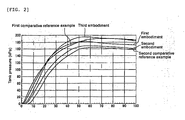
- Fig. 2 is a graph showing experiment results relating to comparative reference examples and embodiments of the present invention.
- Fig. 2 shows temporal variation in a post-ignition tank pressure of the gas generator when a charging ratio of the ignition agent 22 is adjusted relative to the volume of the ignition agent housing chamber 16.
- the ordinate shows the tank pressure and the abscissa shows the passage of time from the moment at which ignition is performed by the initiator.
- Fig. 2 shows first and second comparative reference examples and first, second and third embodiments.
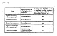
- Fig. 3 is a table showing relative charging amounts of the gas generating agent 24 and the ignition agent 22 in the comparative reference examples and the embodiments of the present invention.
- the tank pressure at an initial activation stage of the gas generator can be suppressed below that of the comparative reference examples when the charging ratio of the ignition agent is 50% or less.
- a tank pressure increase start time may be delayed, leading to delays in airbag inflation and passenger restraint.
- the tank pressure increase start time is not delayed to a problematic extent.
- tank pressures shown in Fig. 2 were measured in a tank combustion test employing the following method.
- a gas generator for an airbag is fixed in the interior of a tank (made of stainless steel or aluminum) having an interior volume of 60 liters, whereupon the tank is sealed at room temperature and connected to an external ignition electric circuit.
- a switch of the ignition electric circuit is turned ON (an ignition current is applied) by a pressure transducer disposed separately in the tank at a time 0, whereupon upward variation in the tank pressure is measured for a period of 0 to 100 milliseconds.
- respective measurement data are turned into a tank pressure/time curve by computer processing, and as a result, a curve (to be referred to hereafter as a "tank curve”) for evaluating the performance of a gas generating agent molded body is obtained.
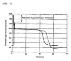
- Figs. 4 and 5 are graphs showing a characteristic of the gas generator for an airbag device according to the third embodiment of the present invention.
- Fig. 4 shows temporal displacement in the gas generation amount (mass flow) of the gas generator, wherein the gas generator according to the third embodiment is indicated by a solid line and the gas generator according to the first comparative reference example is indicated by a broken line. It is evident from Fig. 4 that with the structure according to this embodiment, the gas generation amount can be suppressed to a low level at the initial activation stage of the gas generator (airbag device). Thereafter, i.e. from the intermediate stage to the late stage of activation, a sufficient gas amount is obtained.
- Fig. 5 shows temporal displacement in a generated gas temperature of the gas generator, wherein the gas generator according to the third embodiment is indicated by a solid line and the gas generator according to the first comparative reference example is indicated by a broken line. It is evident from Fig. 5 that with the structure according to this embodiment, the gas temperature can be suppressed to a low level at the initial activation stage of the gas generator (airbag device) . Thereafter, i.e. from the intermediate stage to the late stage of activation, substantially identical behavior to that of a conventional gas generator is exhibited.
- the airbag is inflated gently by a comparatively small amount of gas and at a comparatively low gas temperature and a comparatively low gas pressure. Therefore, damage to the airbag module and harm to an occupant can be reduced. Thereafter, the airbag is inflated and deployed by a sufficient amount of gas and at a sufficient gas temperature and a sufficient gas pressure, and therefore the occupant is restrained appropriately.
- the amount of charged gas generating agent is approximately 10% greater than a normal charging amount, but as long as conditions such as charging density are satisfied, another charging ratio may be employed. More specifically, the amount of gas generating agent may be increased within a range that does not impair the effects of the present invention, or in other words by a maximum of approximately 20% relative to a standard gas generating agent amount.
Landscapes
- Physics & Mathematics (AREA)
- Fluid Mechanics (AREA)
- Engineering & Computer Science (AREA)
- Mechanical Engineering (AREA)
- Air Bags (AREA)
- Feeding, Discharge, Calcimining, Fusing, And Gas-Generation Devices (AREA)
Abstract
Description
- The present invention relates to an airbag device and a gas generator installed in a vehicle, and more particularly to an improvement in a gas generator for an airbag device having a featured activation performance.
- Vehicles such as automobiles are installed with an airbag system that prevents serious injury or death occurring when an occupant crashes into a hard part in the interior of the vehicle, such as a steering wheel or a front windshield, during a collision or the like by rapidly inflating a bag with gas so that the occupant is prevented from crashing into dangerous locations.
- An airbag system is preferably capable of restraining the occupant safely regardless of the body shape (for example, a sitting height and so on) of the occupant, the attitude of the occupant (for example, when the occupant is clinging to the steering wheel), and so on. Hence, airbag systems that are activated such that minimal impact is applied to the occupant during an initial activation stage have been proposed in the related art.
- In Japanese Patent Application Publication No.
H8-207696 - [Patent Document 1] Japanese Patent Application Publication No.
H8-207696 -
U.S. Patent No. 4, 998, 751 andU.S. Patent No. 4, 950, 458 similarly propose that an activation function of the gas generator be restricted by providing two combustion chambers such that the gas generating agent is burned in two stages. However, a similar increase in structural complexity occurs in this case, and therefore these proposals cannot be considered satisfactory. - [Patent Document 2]
U.S. Patent No. 4,998,751 - [Patent Document 3]
U.S. Patent No. 4,950,458 - Furthermore, Japanese Patent Application Publication No.
H11-334517 - [Patent Document 4] Japanese Patent Application Publication No.
H11-334517 - The present invention has been designed in consideration of the conditions described above, and an object thereof is to provide an airbag device and a gas generator used therein with which damage to an airbag module and an impact on an occupant can be reduced during an initial activation stage and the occupant can be restrained reliably while maintaining structural simplicity.
- A gas generator for an airbag device according to a first aspect of the present invention includes: an initiator (igniter) that is activated by an impact on the vehicle; an ignition agent that is ignited by the initiator; an ignition agent housing chamber housing the ignition agent; a gas generating agent that is.ignited and burned by the ignition agent; and a combustion chamber housing the gas generating agent. An airbag is inflated by a gas generated through combustion of the gas generating agent. Further, a space into which the ignition agent is not charged is formed in the ignition agent housing chamber.
- An airbag device according to a second aspect of the present invention includes, in addition to the gas generator described above, an airbag that is inflated and deployed by a gas generated by the gas generator.
- The ignition agent preferably occupies 30% to 50% of an interior volume of the ignition agent housing chamber such that the remainder constitutes the space.
- According to the present invention constituted as described above, activation can be performed such that minimal impact is applied to the occupant during the initial activation stage and the occupant can be restrained reliably while maintaining structural simplicity.
-
-
Fig. 1 is a schematic sectional view showing the structure of a gas generator for an airbag device according to an embodiment of the present invention; -
Fig. 2 is a graph showing a characteristic of the gas generator for an airbag device according to an embodiment of the present invention; -
Fig. 3 is a table showing relative charging amounts of a gas generating agent and an ignition agent in the gas generator for an airbag device according to an embodiment of the present invention; -
Fig. 4 is a graph showing characteristics of gas generators for an airbag device according to a comparative reference example and an embodiment of the present invention; and -
Fig. 5 is a graph showing characteristics of gas generators for an airbag device according to a comparative reference example and an embodiment of the present invention. -
Fig. 6 is a schematic sectional view showing the structure of a gas generator for an airbag device according to an embodiment of the present invention; -
- 10
- gas generator for airbag device
- 12
- housing
- 14
- igniter (initiator)
- 16
- ignition agent housing chamber
- 18
- gas generating agent combustion chamber
- 20
- coolant filter
- 22
- ignition agent
- 24
- gas generating agent
- 26
- gas flow passage of
ignition agent 22 - 28
- gas discharge port
-
Fig. 1 is a schematic sectional view showing the structure of a gas generator for an airbag device according to an embodiment of the present invention. Agas generator 10 for an airbag device according to this embodiment includes an initiator (igniter) 14 that is activated by an impact on a vehicle, anignition agent 22 that is ignited by theinitiator 14, an ignitionagent housing chamber 16 housing theignition agent 22, agas generating agent 24 that is ignited and burned by theignition agent 22, and acombustion chamber 18 housing thegas generating agent 24. - The
gas generator 10 according to this embodiment is structured to inflate an airbag using gas generated when thegas generating agent 24 is burned. A feature of this embodiment is that a space in which theignition agent 22 is not charged is formed in the interior of the ignitionagent housing chamber 16. Theignition agent 22 is preferably charged to approximately 30% to 50% of the interior volume of the ignitionagent housing chamber 16 so that the remainder forms the space. - A state shown in
Fig. 1 is a condition of a moving vehicle, for example. Theignition agent 22 is not settled. On the other hand, when the vehicle is parked ( non moving condition), for example, theignition agent 22 is settled downward as shown inFig. 6 , and the space in which theignition agent 22 is not charged expands in an upper part of the ignitionagent housing chamber 16. - The
gas generator 10 also includes ahousing 12 constituted by an upper/lower pair of shells. Thehousing 12 may be molded by casting, forging, pressing, and so on. A plurality ofgas discharge ports 28 having a diameter of approximately 3mm, for example, are provided in a circumferential direction in a peripheral wall portion of the housing 12 (for example, eighteen discharge ports are provided at equal intervals) such that the airbag (not shown) is inflated and deployed by gas discharged through thedischarge ports 28. - An
igniter cup 16a forming the ignitionagent housing chamber 16 described above may be formed by a method such as casting, forging, pressing, or cutting, or a combination thereof. Theinitiator 14 is provided in theigniter cup 16a and theignition agent 22 is housed therein. A throughhole 26 is formed in a peripheral wall of theigniter cup 16a as a flow passage for a flame by which thegas generating agent 24 in thecombustion chamber 18 is burned. - A
coolant filter 20 that purifies and cools the gas generated by ignition and combustion of thegas generating agent 24 is provided in thehousing 12. Thecoolant filter 20 is disposed so as to surround thegas generating agent 24, thereby defining an annular chamber, or in other words the gas generatingagent combustion chamber 18, on the periphery of theigniter cup 16a. Thecoolant filter 20 may be molded by overlapping gauze made of stainless steel, for example, in a radial direction and then compressing the overlapped gauze in the radial direction and an axial direction. - Similarly to the ignition
agent housing chamber 16, thecombustion chamber 18 may be formed with a space in which thegas generating agent 24 does not exist. However, when an excessively large space (10% or more of the total volume, for example) is formed, a gas generation amount decreases, and therefore the space is preferably made as small as possible. -
Fig. 2 is a graph showing experiment results relating to comparative reference examples and embodiments of the present invention.Fig. 2 shows temporal variation in a post-ignition tank pressure of the gas generator when a charging ratio of theignition agent 22 is adjusted relative to the volume of the ignitionagent housing chamber 16. The ordinate shows the tank pressure and the abscissa shows the passage of time from the moment at which ignition is performed by the initiator.Fig. 2 shows first and second comparative reference examples and first, second and third embodiments. -
Fig. 3 is a table showing relative charging amounts of thegas generating agent 24 and theignition agent 22 in the comparative reference examples and the embodiments of the present invention. - As shown in
Fig. 2 , with the structure of this embodiment, the tank pressure at an initial activation stage of the gas generator (airbag device) can be suppressed below that of the comparative reference examples when the charging ratio of the ignition agent is 50% or less. When the charging ratio of the ignition agent is reduced, a tank pressure increase start time may be delayed, leading to delays in airbag inflation and passenger restraint. However, as long as the charging ratio is at least 30%, the tank pressure increase start time is not delayed to a problematic extent. - Meanwhile, when the charging ratio of the
ignition agent 22 is reduced relative to the volume of the ignitionagent housing chamber 16, a maximum value of the tank pressure also decreases below that of the first comparative reference example, as shown inFig. 2 . A small decrease does not pose a problem. However, it is evident from the embodiment in which the charging amount of thegas generating agent 24 is increased that by increasing the amount of gas generating agent, an equal maximum value to that of the first comparative reference example can be obtained while reducing the tank pressure during the initial activation stage. In the third embodiment, sufficient tank pressure is obtained from an intermediate stage to a late stage of activation. - Note that the tank pressures shown in
Fig. 2 were measured in a tank combustion test employing the following method. A gas generator for an airbag is fixed in the interior of a tank (made of stainless steel or aluminum) having an interior volume of 60 liters, whereupon the tank is sealed at room temperature and connected to an external ignition electric circuit. A switch of the ignition electric circuit is turned ON (an ignition current is applied) by a pressure transducer disposed separately in the tank at atime 0, whereupon upward variation in the tank pressure is measured for a period of 0 to 100 milliseconds. Finally, respective measurement data are turned into a tank pressure/time curve by computer processing, and as a result, a curve (to be referred to hereafter as a "tank curve") for evaluating the performance of a gas generating agent molded body is obtained. -
Figs. 4 and5 are graphs showing a characteristic of the gas generator for an airbag device according to the third embodiment of the present invention.Fig. 4 shows temporal displacement in the gas generation amount (mass flow) of the gas generator, wherein the gas generator according to the third embodiment is indicated by a solid line and the gas generator according to the first comparative reference example is indicated by a broken line. It is evident fromFig. 4 that with the structure according to this embodiment, the gas generation amount can be suppressed to a low level at the initial activation stage of the gas generator (airbag device). Thereafter, i.e. from the intermediate stage to the late stage of activation, a sufficient gas amount is obtained. -
Fig. 5 shows temporal displacement in a generated gas temperature of the gas generator, wherein the gas generator according to the third embodiment is indicated by a solid line and the gas generator according to the first comparative reference example is indicated by a broken line. It is evident fromFig. 5 that with the structure according to this embodiment, the gas temperature can be suppressed to a low level at the initial activation stage of the gas generator (airbag device) . Thereafter, i.e. from the intermediate stage to the late stage of activation, substantially identical behavior to that of a conventional gas generator is exhibited. - As described above, during the initial activation stage of the airbag device according to this embodiment, the airbag is inflated gently by a comparatively small amount of gas and at a comparatively low gas temperature and a comparatively low gas pressure. Therefore, damage to the airbag module and harm to an occupant can be reduced. Thereafter, the airbag is inflated and deployed by a sufficient amount of gas and at a sufficient gas temperature and a sufficient gas pressure, and therefore the occupant is restrained appropriately.
- Embodiments of the present invention were described above, but the present invention is not limited to the above embodiments, and various design modifications and so on may be implemented within a scope that does not depart from the technical spirit of the claims.
- For example, in the third embodiment, the amount of charged gas generating agent is approximately 10% greater than a normal charging amount, but as long as conditions such as charging density are satisfied, another charging ratio may be employed. More specifically, the amount of gas generating agent may be increased within a range that does not impair the effects of the present invention, or in other words by a maximum of approximately 20% relative to a standard gas generating agent amount.
Claims (4)
- A gas generator for an airbag device installed in a vehicle, characterized by comprising:an initiator (igniter) that is activated by an impact on said vehicle;an ignition agent that is ignited by said initiator;an ignition agent housing chamber housing said ignition agent;a gas generating agent that is ignited and burned by said ignition agent; anda combustion chamber housing said gas generating agent,wherein an airbag is inflated by a gas generated through combustion of said gas generating agent, anda space into which said ignition agent is not charged is formed in said ignition agent housing chamber.
- The gas generator according to claim 1, characterized in that said ignition agent occupies 30% to 50% of an interior volume of said ignition agent housing chamber, and a remainder of said ignition agent housing chamber constitutes said space.
- An airbag device characterized by comprising:said gas generator according to claim 1; andan airbag that is inflated and deployed by a gas generated by said gas generator.
- The airbag device according to claim 3, characterized in that said ignition agent occupies 30% to 50% of an interior volume of said ignition agent housing chamber, and a remainder of said ignition agent housing chamber constitutes said space.
Applications Claiming Priority (2)
| Application Number | Priority Date | Filing Date | Title |
|---|---|---|---|
| JP2009053407 | 2009-03-06 | ||
| JP2010029630A JP5667367B2 (en) | 2009-03-06 | 2010-02-15 | Air bag apparatus and gas generator used therefor |
Publications (2)
| Publication Number | Publication Date |
|---|---|
| EP2226222A1 true EP2226222A1 (en) | 2010-09-08 |
| EP2226222B1 EP2226222B1 (en) | 2013-04-24 |
Family
ID=42237093
Family Applications (1)
| Application Number | Title | Priority Date | Filing Date |
|---|---|---|---|
| EP10002334.0A Not-in-force EP2226222B1 (en) | 2009-03-06 | 2010-03-05 | Air bag device and gas generator used therein |
Country Status (4)
| Country | Link |
|---|---|
| US (1) | US8096580B2 (en) |
| EP (1) | EP2226222B1 (en) |
| JP (1) | JP5667367B2 (en) |
| CN (1) | CN101823469B (en) |
Families Citing this family (2)
| Publication number | Priority date | Publication date | Assignee | Title |
|---|---|---|---|---|
| US8997655B1 (en) * | 2009-06-04 | 2015-04-07 | Tk Holdings Inc. | Gas generating system |
| US8882143B2 (en) * | 2013-02-08 | 2014-11-11 | Autoliv Asp, Inc. | Airbag with slit vent |
Citations (7)
| Publication number | Priority date | Publication date | Assignee | Title |
|---|---|---|---|---|
| US4950458A (en) | 1989-06-22 | 1990-08-21 | Morton International, Inc. | Passenger automotive restraint generator |
| US4998751A (en) | 1990-03-26 | 1991-03-12 | Morton International, Inc. | Two-stage automotive gas bag inflator using igniter material to delay second stage ignition |
| JPH08207696A (en) | 1994-05-04 | 1996-08-13 | Breed Automot Technol Inc | Air bag device |
| EP0864553A1 (en) * | 1995-12-01 | 1998-09-16 | Kabushiki Kaisha Kobeseikosho | Gas generating agent and transfer charge for use in airbag gas generator, and gas generator comprising said gas generating agent and transfer charge |
| JPH11334517A (en) | 1997-12-26 | 1999-12-07 | Daicel Chem Ind Ltd | Gas generator for air bag and air gab device |
| US20050039623A1 (en) * | 2003-08-08 | 2005-02-24 | Takata Corporation | Initiator for a gas generator |
| US20070085314A1 (en) * | 2005-10-14 | 2007-04-19 | Daicel Chemical Industries, Ltd. | Gas generator for airbag |
Family Cites Families (16)
| Publication number | Priority date | Publication date | Assignee | Title |
|---|---|---|---|---|
| JPH1159314A (en) * | 1997-08-12 | 1999-03-02 | Daicel Chem Ind Ltd | Gas generator for air bag |
| JP2000016226A (en) * | 1998-06-26 | 2000-01-18 | Daicel Chem Ind Ltd | Gas generator and airbag device for airbag |
| TW469235B (en) * | 1999-10-04 | 2001-12-21 | Daicel Chem | Gas generator for air bag and air bag device |
| AU2001234104A1 (en) * | 2000-02-22 | 2001-09-03 | Daicel Chemical Industries Ltd. | Airbag gas generator, deflector member, coolant/filter means support member, coolant, and housing |
| WO2002051675A1 (en) * | 2000-12-27 | 2002-07-04 | Daicel Chemical Industries, Ltd. | Air bag-use gas generator and air bag device |
| EP1473202A1 (en) * | 2002-02-06 | 2004-11-03 | Nippon Kayaku Kabushiki Kaisha | Gas generator |
| US7125041B2 (en) * | 2003-01-15 | 2006-10-24 | Daicel Chemical Industries, Ltd. | Gas generator |
| JP2004230922A (en) * | 2003-01-28 | 2004-08-19 | Nippon Kayaku Co Ltd | Gas generator |
| JP3696870B1 (en) * | 2004-03-30 | 2005-09-21 | 日本化薬株式会社 | Gas generator |
| DE102004063268A1 (en) * | 2004-12-24 | 2006-07-13 | Takata-Petri (Ulm) Gmbh | Occupant protection device |
| US7556289B2 (en) * | 2005-07-29 | 2009-07-07 | Daicel Chemical Industries, Ltd. | Gas generator for air bag |
| JP4878206B2 (en) * | 2006-04-28 | 2012-02-15 | 株式会社ダイセル | Inflator |
| JP2008062685A (en) * | 2006-09-05 | 2008-03-21 | Daicel Chem Ind Ltd | Apparatus with igniter assembly |
| US7591483B2 (en) * | 2006-11-06 | 2009-09-22 | Daicel Chemical Industries, Ltd. | Gas generator for restraining device for vehicle |
| JP4332189B2 (en) * | 2007-08-09 | 2009-09-16 | トヨタ自動車株式会社 | Inflator and vehicle airbag apparatus using the same |
| JP4953998B2 (en) * | 2007-09-18 | 2012-06-13 | 株式会社ダイセル | Gas generator for personnel restraint system |
-
2010
- 2010-02-15 JP JP2010029630A patent/JP5667367B2/en not_active Expired - Fee Related
- 2010-03-02 CN CN201010117117XA patent/CN101823469B/en not_active Expired - Fee Related
- 2010-03-04 US US12/717,409 patent/US8096580B2/en not_active Expired - Fee Related
- 2010-03-05 EP EP10002334.0A patent/EP2226222B1/en not_active Not-in-force
Patent Citations (7)
| Publication number | Priority date | Publication date | Assignee | Title |
|---|---|---|---|---|
| US4950458A (en) | 1989-06-22 | 1990-08-21 | Morton International, Inc. | Passenger automotive restraint generator |
| US4998751A (en) | 1990-03-26 | 1991-03-12 | Morton International, Inc. | Two-stage automotive gas bag inflator using igniter material to delay second stage ignition |
| JPH08207696A (en) | 1994-05-04 | 1996-08-13 | Breed Automot Technol Inc | Air bag device |
| EP0864553A1 (en) * | 1995-12-01 | 1998-09-16 | Kabushiki Kaisha Kobeseikosho | Gas generating agent and transfer charge for use in airbag gas generator, and gas generator comprising said gas generating agent and transfer charge |
| JPH11334517A (en) | 1997-12-26 | 1999-12-07 | Daicel Chem Ind Ltd | Gas generator for air bag and air gab device |
| US20050039623A1 (en) * | 2003-08-08 | 2005-02-24 | Takata Corporation | Initiator for a gas generator |
| US20070085314A1 (en) * | 2005-10-14 | 2007-04-19 | Daicel Chemical Industries, Ltd. | Gas generator for airbag |
Also Published As
| Publication number | Publication date |
|---|---|
| CN101823469A (en) | 2010-09-08 |
| JP2010228747A (en) | 2010-10-14 |
| CN101823469B (en) | 2012-11-21 |
| EP2226222B1 (en) | 2013-04-24 |
| US8096580B2 (en) | 2012-01-17 |
| JP5667367B2 (en) | 2015-02-12 |
| US20100225099A1 (en) | 2010-09-09 |
Similar Documents
| Publication | Publication Date | Title |
|---|---|---|
| EP2426015B1 (en) | Gas generator | |
| US7178831B2 (en) | Gas generator | |
| US6012737A (en) | Vehicle occupant protection apparatus | |
| JPH02169347A (en) | Gas generator | |
| JP5189083B2 (en) | Inflator device with modular structure and radial flow of inflation gas | |
| EP1658204A1 (en) | Pyrotechnique side impact inflator | |
| US9016207B2 (en) | Gas generator for airbag device | |
| US9205802B1 (en) | Hybrid inflator device for a passive restraint air bag system | |
| US7506891B2 (en) | Belt and side impact inflator | |
| US5951042A (en) | Vehicle occupant protection apparatus | |
| EP2226222B1 (en) | Air bag device and gas generator used therein | |
| JP2004513862A (en) | Tablet shape of gas generating material | |
| JPH10315900A (en) | Gas generator for air bag, and air bag device | |
| JP2007314050A (en) | Device including igniter | |
| US7114746B2 (en) | Air bag-use gas generator and air bag device | |
| WO2004045909A2 (en) | Projecile firing barrel | |
| CN211223356U (en) | Automobile safety air bag and gas generator | |
| JP5231346B2 (en) | Gas generator for airbag device and method for manufacturing the same | |
| JP4542698B2 (en) | Gas generator for airbag and airbag device | |
| JP5586853B2 (en) | Gas generator for airbag device, jig for assembling gas generator, and assembling method of gas generator | |
| EP1841623B1 (en) | An air-bag inflator | |
| KR100353071B1 (en) | Multi-stage airbag system using gas controller for automobile | |
| JP2002193069A (en) | Gas generator for airbag and airbag device | |
| KR19980048893U (en) | Cushion of car airbag |
Legal Events
| Date | Code | Title | Description |
|---|---|---|---|
| PUAI | Public reference made under article 153(3) epc to a published international application that has entered the european phase |
Free format text: ORIGINAL CODE: 0009012 |
|
| AK | Designated contracting states |
Kind code of ref document: A1 Designated state(s): AT BE BG CH CY CZ DE DK EE ES FI FR GB GR HR HU IE IS IT LI LT LU LV MC MK MT NL NO PL PT RO SE SI SK SM TR |
|
| AX | Request for extension of the european patent |
Extension state: AL BA ME RS |
|
| 17P | Request for examination filed |
Effective date: 20100825 |
|
| 17Q | First examination report despatched |
Effective date: 20101102 |
|
| RAP1 | Party data changed (applicant data changed or rights of an application transferred) |
Owner name: AUTOLIV ASP, INC. |
|
| GRAP | Despatch of communication of intention to grant a patent |
Free format text: ORIGINAL CODE: EPIDOSNIGR1 |
|
| GRAS | Grant fee paid |
Free format text: ORIGINAL CODE: EPIDOSNIGR3 |
|
| GRAA | (expected) grant |
Free format text: ORIGINAL CODE: 0009210 |
|
| AK | Designated contracting states |
Kind code of ref document: B1 Designated state(s): AT BE BG CH CY CZ DE DK EE ES FI FR GB GR HR HU IE IS IT LI LT LU LV MC MK MT NL NO PL PT RO SE SI SK SM TR |
|
| REG | Reference to a national code |
Ref country code: GB Ref legal event code: FG4D |
|
| REG | Reference to a national code |
Ref country code: CH Ref legal event code: EP |
|
| REG | Reference to a national code |
Ref country code: AT Ref legal event code: REF Ref document number: 608422 Country of ref document: AT Kind code of ref document: T Effective date: 20130515 |
|
| REG | Reference to a national code |
Ref country code: IE Ref legal event code: FG4D |
|
| REG | Reference to a national code |
Ref country code: DE Ref legal event code: R096 Ref document number: 602010006465 Country of ref document: DE Effective date: 20130620 |
|
| REG | Reference to a national code |
Ref country code: AT Ref legal event code: MK05 Ref document number: 608422 Country of ref document: AT Kind code of ref document: T Effective date: 20130424 |
|
| REG | Reference to a national code |
Ref country code: LT Ref legal event code: MG4D |
|
| REG | Reference to a national code |
Ref country code: NL Ref legal event code: VDEP Effective date: 20130424 |
|
| PG25 | Lapsed in a contracting state [announced via postgrant information from national office to epo] |
Ref country code: GR Free format text: LAPSE BECAUSE OF FAILURE TO SUBMIT A TRANSLATION OF THE DESCRIPTION OR TO PAY THE FEE WITHIN THE PRESCRIBED TIME-LIMIT Effective date: 20130725 Ref country code: NO Free format text: LAPSE BECAUSE OF FAILURE TO SUBMIT A TRANSLATION OF THE DESCRIPTION OR TO PAY THE FEE WITHIN THE PRESCRIBED TIME-LIMIT Effective date: 20130724 Ref country code: PT Free format text: LAPSE BECAUSE OF FAILURE TO SUBMIT A TRANSLATION OF THE DESCRIPTION OR TO PAY THE FEE WITHIN THE PRESCRIBED TIME-LIMIT Effective date: 20130826 Ref country code: SI Free format text: LAPSE BECAUSE OF FAILURE TO SUBMIT A TRANSLATION OF THE DESCRIPTION OR TO PAY THE FEE WITHIN THE PRESCRIBED TIME-LIMIT Effective date: 20130424 Ref country code: BE Free format text: LAPSE BECAUSE OF FAILURE TO SUBMIT A TRANSLATION OF THE DESCRIPTION OR TO PAY THE FEE WITHIN THE PRESCRIBED TIME-LIMIT Effective date: 20130424 Ref country code: LT Free format text: LAPSE BECAUSE OF FAILURE TO SUBMIT A TRANSLATION OF THE DESCRIPTION OR TO PAY THE FEE WITHIN THE PRESCRIBED TIME-LIMIT Effective date: 20130424 Ref country code: ES Free format text: LAPSE BECAUSE OF FAILURE TO SUBMIT A TRANSLATION OF THE DESCRIPTION OR TO PAY THE FEE WITHIN THE PRESCRIBED TIME-LIMIT Effective date: 20130804 Ref country code: AT Free format text: LAPSE BECAUSE OF FAILURE TO SUBMIT A TRANSLATION OF THE DESCRIPTION OR TO PAY THE FEE WITHIN THE PRESCRIBED TIME-LIMIT Effective date: 20130424 Ref country code: FI Free format text: LAPSE BECAUSE OF FAILURE TO SUBMIT A TRANSLATION OF THE DESCRIPTION OR TO PAY THE FEE WITHIN THE PRESCRIBED TIME-LIMIT Effective date: 20130424 Ref country code: SE Free format text: LAPSE BECAUSE OF FAILURE TO SUBMIT A TRANSLATION OF THE DESCRIPTION OR TO PAY THE FEE WITHIN THE PRESCRIBED TIME-LIMIT Effective date: 20130424 Ref country code: IS Free format text: LAPSE BECAUSE OF FAILURE TO SUBMIT A TRANSLATION OF THE DESCRIPTION OR TO PAY THE FEE WITHIN THE PRESCRIBED TIME-LIMIT Effective date: 20130824 |
|
| PG25 | Lapsed in a contracting state [announced via postgrant information from national office to epo] |
Ref country code: PL Free format text: LAPSE BECAUSE OF FAILURE TO SUBMIT A TRANSLATION OF THE DESCRIPTION OR TO PAY THE FEE WITHIN THE PRESCRIBED TIME-LIMIT Effective date: 20130424 Ref country code: LV Free format text: LAPSE BECAUSE OF FAILURE TO SUBMIT A TRANSLATION OF THE DESCRIPTION OR TO PAY THE FEE WITHIN THE PRESCRIBED TIME-LIMIT Effective date: 20130424 Ref country code: HR Free format text: LAPSE BECAUSE OF FAILURE TO SUBMIT A TRANSLATION OF THE DESCRIPTION OR TO PAY THE FEE WITHIN THE PRESCRIBED TIME-LIMIT Effective date: 20130424 Ref country code: CY Free format text: LAPSE BECAUSE OF FAILURE TO SUBMIT A TRANSLATION OF THE DESCRIPTION OR TO PAY THE FEE WITHIN THE PRESCRIBED TIME-LIMIT Effective date: 20130424 Ref country code: BG Free format text: LAPSE BECAUSE OF FAILURE TO SUBMIT A TRANSLATION OF THE DESCRIPTION OR TO PAY THE FEE WITHIN THE PRESCRIBED TIME-LIMIT Effective date: 20130724 |
|
| PG25 | Lapsed in a contracting state [announced via postgrant information from national office to epo] |
Ref country code: DK Free format text: LAPSE BECAUSE OF FAILURE TO SUBMIT A TRANSLATION OF THE DESCRIPTION OR TO PAY THE FEE WITHIN THE PRESCRIBED TIME-LIMIT Effective date: 20130424 Ref country code: EE Free format text: LAPSE BECAUSE OF FAILURE TO SUBMIT A TRANSLATION OF THE DESCRIPTION OR TO PAY THE FEE WITHIN THE PRESCRIBED TIME-LIMIT Effective date: 20130424 Ref country code: SK Free format text: LAPSE BECAUSE OF FAILURE TO SUBMIT A TRANSLATION OF THE DESCRIPTION OR TO PAY THE FEE WITHIN THE PRESCRIBED TIME-LIMIT Effective date: 20130424 |
|
| PG25 | Lapsed in a contracting state [announced via postgrant information from national office to epo] |
Ref country code: IT Free format text: LAPSE BECAUSE OF FAILURE TO SUBMIT A TRANSLATION OF THE DESCRIPTION OR TO PAY THE FEE WITHIN THE PRESCRIBED TIME-LIMIT Effective date: 20130424 Ref country code: RO Free format text: LAPSE BECAUSE OF FAILURE TO SUBMIT A TRANSLATION OF THE DESCRIPTION OR TO PAY THE FEE WITHIN THE PRESCRIBED TIME-LIMIT Effective date: 20130424 Ref country code: NL Free format text: LAPSE BECAUSE OF FAILURE TO SUBMIT A TRANSLATION OF THE DESCRIPTION OR TO PAY THE FEE WITHIN THE PRESCRIBED TIME-LIMIT Effective date: 20130424 |
|
| PLBE | No opposition filed within time limit |
Free format text: ORIGINAL CODE: 0009261 |
|
| STAA | Information on the status of an ep patent application or granted ep patent |
Free format text: STATUS: NO OPPOSITION FILED WITHIN TIME LIMIT |
|
| 26N | No opposition filed |
Effective date: 20140127 |
|
| PGFP | Annual fee paid to national office [announced via postgrant information from national office to epo] |
Ref country code: CZ Payment date: 20140204 Year of fee payment: 5 |
|
| REG | Reference to a national code |
Ref country code: DE Ref legal event code: R097 Ref document number: 602010006465 Country of ref document: DE Effective date: 20140127 |
|
| PGFP | Annual fee paid to national office [announced via postgrant information from national office to epo] |
Ref country code: GB Payment date: 20140110 Year of fee payment: 5 |
|
| PG25 | Lapsed in a contracting state [announced via postgrant information from national office to epo] |
Ref country code: LU Free format text: LAPSE BECAUSE OF FAILURE TO SUBMIT A TRANSLATION OF THE DESCRIPTION OR TO PAY THE FEE WITHIN THE PRESCRIBED TIME-LIMIT Effective date: 20140305 |
|
| REG | Reference to a national code |
Ref country code: CH Ref legal event code: PL |
|
| REG | Reference to a national code |
Ref country code: IE Ref legal event code: MM4A |
|
| REG | Reference to a national code |
Ref country code: FR Ref legal event code: PLFP Year of fee payment: 6 |
|
| PG25 | Lapsed in a contracting state [announced via postgrant information from national office to epo] |
Ref country code: CH Free format text: LAPSE BECAUSE OF NON-PAYMENT OF DUE FEES Effective date: 20140331 Ref country code: LI Free format text: LAPSE BECAUSE OF NON-PAYMENT OF DUE FEES Effective date: 20140331 Ref country code: IE Free format text: LAPSE BECAUSE OF NON-PAYMENT OF DUE FEES Effective date: 20140305 |
|
| PGFP | Annual fee paid to national office [announced via postgrant information from national office to epo] |
Ref country code: DE Payment date: 20150108 Year of fee payment: 6 |
|
| PGFP | Annual fee paid to national office [announced via postgrant information from national office to epo] |
Ref country code: FR Payment date: 20150111 Year of fee payment: 6 |
|
| PG25 | Lapsed in a contracting state [announced via postgrant information from national office to epo] |
Ref country code: CZ Free format text: LAPSE BECAUSE OF NON-PAYMENT OF DUE FEES Effective date: 20150305 |
|
| GBPC | Gb: european patent ceased through non-payment of renewal fee |
Effective date: 20150305 |
|
| PG25 | Lapsed in a contracting state [announced via postgrant information from national office to epo] |
Ref country code: GB Free format text: LAPSE BECAUSE OF NON-PAYMENT OF DUE FEES Effective date: 20150305 |
|
| PG25 | Lapsed in a contracting state [announced via postgrant information from national office to epo] |
Ref country code: MT Free format text: LAPSE BECAUSE OF FAILURE TO SUBMIT A TRANSLATION OF THE DESCRIPTION OR TO PAY THE FEE WITHIN THE PRESCRIBED TIME-LIMIT Effective date: 20130424 |
|
| PG25 | Lapsed in a contracting state [announced via postgrant information from national office to epo] |
Ref country code: SM Free format text: LAPSE BECAUSE OF FAILURE TO SUBMIT A TRANSLATION OF THE DESCRIPTION OR TO PAY THE FEE WITHIN THE PRESCRIBED TIME-LIMIT Effective date: 20130424 |
|
| PG25 | Lapsed in a contracting state [announced via postgrant information from national office to epo] |
Ref country code: MC Free format text: LAPSE BECAUSE OF FAILURE TO SUBMIT A TRANSLATION OF THE DESCRIPTION OR TO PAY THE FEE WITHIN THE PRESCRIBED TIME-LIMIT Effective date: 20130424 |
|
| PG25 | Lapsed in a contracting state [announced via postgrant information from national office to epo] |
Ref country code: TR Free format text: LAPSE BECAUSE OF FAILURE TO SUBMIT A TRANSLATION OF THE DESCRIPTION OR TO PAY THE FEE WITHIN THE PRESCRIBED TIME-LIMIT Effective date: 20130424 Ref country code: HU Free format text: LAPSE BECAUSE OF FAILURE TO SUBMIT A TRANSLATION OF THE DESCRIPTION OR TO PAY THE FEE WITHIN THE PRESCRIBED TIME-LIMIT; INVALID AB INITIO Effective date: 20100305 |
|
| REG | Reference to a national code |
Ref country code: DE Ref legal event code: R119 Ref document number: 602010006465 Country of ref document: DE |
|
| REG | Reference to a national code |
Ref country code: FR Ref legal event code: ST Effective date: 20161130 |
|
| PG25 | Lapsed in a contracting state [announced via postgrant information from national office to epo] |
Ref country code: FR Free format text: LAPSE BECAUSE OF NON-PAYMENT OF DUE FEES Effective date: 20160331 Ref country code: DE Free format text: LAPSE BECAUSE OF NON-PAYMENT OF DUE FEES Effective date: 20161001 |
|
| PG25 | Lapsed in a contracting state [announced via postgrant information from national office to epo] |
Ref country code: MK Free format text: LAPSE BECAUSE OF FAILURE TO SUBMIT A TRANSLATION OF THE DESCRIPTION OR TO PAY THE FEE WITHIN THE PRESCRIBED TIME-LIMIT Effective date: 20130424 |