EP2226199A1 - Mailpiece conveyance system - Google Patents
Mailpiece conveyance system Download PDFInfo
- Publication number
- EP2226199A1 EP2226199A1 EP10153433A EP10153433A EP2226199A1 EP 2226199 A1 EP2226199 A1 EP 2226199A1 EP 10153433 A EP10153433 A EP 10153433A EP 10153433 A EP10153433 A EP 10153433A EP 2226199 A1 EP2226199 A1 EP 2226199A1
- Authority
- EP
- European Patent Office
- Prior art keywords
- compliant
- mailpieces
- deck
- compliant deck
- feed path
- Prior art date
- Legal status (The legal status is an assumption and is not a legal conclusion. Google has not performed a legal analysis and makes no representation as to the accuracy of the status listed.)
- Granted
Links
Images


Classifications
-
- G—PHYSICS
- G07—CHECKING-DEVICES
- G07B—TICKET-ISSUING APPARATUS; FARE-REGISTERING APPARATUS; FRANKING APPARATUS
- G07B17/00—Franking apparatus
- G07B17/00459—Details relating to mailpieces in a franking system
-
- B—PERFORMING OPERATIONS; TRANSPORTING
- B41—PRINTING; LINING MACHINES; TYPEWRITERS; STAMPS
- B41J—TYPEWRITERS; SELECTIVE PRINTING MECHANISMS, i.e. MECHANISMS PRINTING OTHERWISE THAN FROM A FORME; CORRECTION OF TYPOGRAPHICAL ERRORS
- B41J11/00—Devices or arrangements of selective printing mechanisms, e.g. ink-jet printers or thermal printers, for supporting or handling copy material in sheet or web form
- B41J11/0035—Handling copy materials differing in thickness
-
- B—PERFORMING OPERATIONS; TRANSPORTING
- B41—PRINTING; LINING MACHINES; TYPEWRITERS; STAMPS
- B41J—TYPEWRITERS; SELECTIVE PRINTING MECHANISMS, i.e. MECHANISMS PRINTING OTHERWISE THAN FROM A FORME; CORRECTION OF TYPOGRAPHICAL ERRORS
- B41J11/00—Devices or arrangements of selective printing mechanisms, e.g. ink-jet printers or thermal printers, for supporting or handling copy material in sheet or web form
- B41J11/007—Conveyor belts or like feeding devices
-
- B—PERFORMING OPERATIONS; TRANSPORTING
- B41—PRINTING; LINING MACHINES; TYPEWRITERS; STAMPS
- B41J—TYPEWRITERS; SELECTIVE PRINTING MECHANISMS, i.e. MECHANISMS PRINTING OTHERWISE THAN FROM A FORME; CORRECTION OF TYPOGRAPHICAL ERRORS
- B41J11/00—Devices or arrangements of selective printing mechanisms, e.g. ink-jet printers or thermal printers, for supporting or handling copy material in sheet or web form
- B41J11/0085—Using suction for maintaining printing material flat
-
- B—PERFORMING OPERATIONS; TRANSPORTING
- B41—PRINTING; LINING MACHINES; TYPEWRITERS; STAMPS
- B41J—TYPEWRITERS; SELECTIVE PRINTING MECHANISMS, i.e. MECHANISMS PRINTING OTHERWISE THAN FROM A FORME; CORRECTION OF TYPOGRAPHICAL ERRORS
- B41J25/00—Actions or mechanisms not otherwise provided for
- B41J25/304—Bodily-movable mechanisms for print heads or carriages movable towards or from paper surface
- B41J25/312—Bodily-movable mechanisms for print heads or carriages movable towards or from paper surface with print pressure adjustment mechanisms, e.g. pressure-on-the paper mechanisms
-
- G—PHYSICS
- G07—CHECKING-DEVICES
- G07B—TICKET-ISSUING APPARATUS; FARE-REGISTERING APPARATUS; FRANKING APPARATUS
- G07B17/00—Franking apparatus
- G07B17/00459—Details relating to mailpieces in a franking system
- G07B17/00467—Transporting mailpieces
-
- G—PHYSICS
- G07—CHECKING-DEVICES
- G07B—TICKET-ISSUING APPARATUS; FARE-REGISTERING APPARATUS; FRANKING APPARATUS
- G07B17/00—Franking apparatus
- G07B17/00459—Details relating to mailpieces in a franking system
- G07B17/00508—Printing or attaching on mailpieces
- G07B2017/00516—Details of printing apparatus
- G07B2017/00556—Ensuring quality of print
Definitions
- the present invention relates to a system and method for processing mailpieces and more particularly, to a new and useful compliant conveyance system operative to process mailpieces (e.g., print on a face surface thereof) which vary in thickness.
- Mailpiece creation systems such as mailpiece inserters are typically used by organizations such as banks, insurance companies, and utility companies to periodically produce a large volume of mailpieces, e.g., monthly billing or shareholders income/dividend statements.
- mailpiece inserters are analogous to automated assembly equipment inasmuch as sheets, inserts and envelopes are conveyed along a feed path and assembled in or at various modules of the mailpiece inserter. That is, the various modules work cooperatively to process the sheets until a finished mailpiece is produced.
- a mailpiece inserter includes a variety of apparatus/modules for conveying and processing sheet material along the feed path.
- mailpiece inserters include apparatus/modules for (i) feeding and singulating printed content material in a "feeder module”, (ii) accumulating the content material to form a multi-sheet collation in an "accumulator”, (iii) folding the content material to produce a variety of fold configurations such as a C-fold, Z-fold, bi-fold and gate fold, in a "folder”, (iv) feeding mailpiece inserts such as coupons, brochures, and pamphlets, in combination with the content material, in a "chassis module” (v) inserting the folded/unfolded and/or nested content material into an envelope in an "envelope inserter", (vi) sealing the filled envelope in "sealing module” (vii) printing recipient/return addresses and/or postage indicia on the face of the mailpiece envelope at a "print station” and (viii) controlling the flow and
- mailpiece inserter may also include other modules for (i) binding/ to close the module to dose and seal filled mailpiece envelopes and a (vi) a printing module for addressing and/or printing postage indicia.
- the printing module it is common to register a face surface of each mailpiece with a registration plate such that an array of print heads may print information such as destination and return addresses on the face of each mailpiece.
- the registration plate includes an aperture for accepting a stepped array of print head nozzles. The thickness of the registration plate provides a threshold "stand-off" dimension from the face surface of each mailpiece to each of the print head nozzles such that ink droplets may be precisely deposited.
- the array of print heads and registration plate are typically disposed over, and in opposed relation to, and underlying conveyance system such as one or more conveyor belts.
- Mailpieces are conveyed along the belt(s), move under the registration plate and passed by the print head nozzles as ink is deposited.
- the spacing between the underlying conveyance system, e.g., the conveyance belt (s), and the registration plate must be closely controlled. That is, with each mail run/print job performed by the print module, the necessary clearance gap must be established based upon the anticipated thickness of mailpieces being processed.
- print head modules and underlying conveyance systems are typically limited to processing mailpieces having a constant, i.e., non-variable, thickness dimension. While such print head modules are capable of printing on thin and thick mailpieces, they are unable to print consecutive thin and thick mailpieces inasmuch as the clearance gap differs for each of the mailpieces.
- the mailpieces are conveyed along a feed path to the print heads by a vacuum manifold system.
- the vacuum manifold system develops a pressure differential across each of the mailpieces to urge each mailpiece into frictional engagement with one or more conveyor belts.
- a fluid communication path is created from the drive surface of the conveyor belts to a vacuum source by a combination of apertures, conduits and plenums. More specifically, rows of apertures are typically formed in the belts which communicate with a combination of elongate slots and circular apertures formed in the underlying support deck.
- a system of plenums are disposed beneath, and attached to an underside surface of, the support deck to draw air through the apertures of the belt and elongate slots/circular apertures of the support deck.
- the elongate slots are aligned with the apertures formed in the belts to ensure a flow of air to each of the apertures as the belts are driven along the feed path.
- elongate slots are fabricated to maintain a threshold thickness dimension. That is, by maintaining a threshold minimum thickness, deformation of the belt may be obviated to prevent the belt from restricting or closing the flow through the slots and circular apertures of the support deck.
- a compliant conveyance system for processing mailpieces along a feed path, e.g., printing on a first surface of a mailpiece, while being registered against a contact surface of a registration plate.
- the conveyance system comprises at least one conveyor belt opposing the contact surface of the registration plate, a continuous, uninterrupted, compliant deck disposed beneath and supporting an underside surface of the conveyor belt, and a spring biasing device operative to bias the compliant deck and the conveyor belt toward the contact surface of the registration plate.
- the conveyor belt includes a drive surface for engaging a second surface of each of the mailpieces for conveyance along the feed path. As each of the mailpieces pass the registration plate, the compliant deck and spring biasing device urge the second surface of each mailpiece into engagement with the contact surface during processing.
- the invention is described in the context of a printing module and underlying conveyance system for a mailpiece inserter, though it will be appreciated that the system and method described herein is applicable to processing variable thickness mailpieces which are fed consecutively. Furthermore, the system and method of the present invention is applicable to mailpieces wherein a face surface thereof is disposed in register and guided along a registration plate during processing. For example, such registration may be required when inspecting a mailpiece, reading postage indicia or interpreting scan codes on the face of a mailpiece. Consequently, the detailed description and illustrations are merely indicative of an embodiment of the invention and the invention should be broadly interpreted in accordance with the appended claims.
- Figs. 1 and 2 depict perspective and top views of a print head assembly 8 disposed over a compliant conveyance system 10.
- the compliant conveyance system 10 is operative to process mailpieces 14 which vary in thickness from about 0.10 inches to about 0.5 inches.
- a compliant deck 12 is provided having a low characteristic stiffness in a direction parallel to the feed path FP of mailpieces being processed and a high characteristic stiffness in a direction orthogonal to the feed path. That is, the characteristic stiffness parallel to the feed path is lower (i.e., 50% or more) than the characteristic stiffness in the orthogonal direction.
- the compliant conveyance system 10 is adapted for operation with a bank of print heads 16 arranged in a staggered or stepped array. Furthermore, the bank of print heads 16 includes a registration/skid plate 18 having a contact surface 18S for registering a first surface 14FS of each mailpiece 14.
- a pivotable support/instrumentation rack (not shown in the subject illustrations) supports the print head module 8, to maintain the position of the print heads 16 relative to the underlying compliant conveyance system, i.e., a clearance gap therebetween.
- the support/instrumentation rack will be discussed in greater detail hereinafter.
- the compliant conveyance system 10 includes at least one conveyor belt 20 having a drive surface 20S which is adapted to oppose the contact surface 18S of the registration plate 18.
- the compliant conveyance system 10 employs three (3) belts 20a, 20b, 20c which are spaced apart, though it should be appreciated that a fewer or greater number of belts 20 may be employed.
- the conveyor belts 20 rotate around a plurality of rollers, e.g., end turn-around rollers 22, 24, tensioning rollers 26, 28 (see Fig. 3 ) and drive rollers (not shown) which are driven by a drive motor (also not shown).
- the end rollers 22, 24 are each mounted for rotation to side beam members 30, 32 to produce a rigid box structure having a generally rectangular shape.
- Each of the side beam members 30, 32 have a generally S-shaped or Z-shaped cross-section wherein an upper flange 30T, 32T (see Figs. 1 and 3 ) projects outwardly away from the conveyor belts 20 and a lower flange 30L, 32L (see Fig. 3 ) projects inwardly toward the conveyor belts 20.
- the web 30W, 32W of at least one of the beam members 30, 32 includes a plurality of apertures 30A, 32A which are used to receive a plurality of flexible tubes 34 employed in a Flexible Manifold Vacuum System 50 (described in greater detail hereinbelow).
- the compliant deck 12 is disposed beneath and supports the conveyor belts 20.
- the compliant deck 12 comprises at least one continuous, i.e., uninterrupted, layer of a high-modulus, low-friction, high yield strength material such as a polished spring steel.
- the compliant deck 12 includes a support layer 40S (see Figs 4 , 5 and 6 ) of spring steel and a surface layer 40T of Teflon® ("Teflon” is a registered trademark of the Dupont Nemours Corporation located in Wilmington, state of Delaware) or Poly-Tetra-Flora-Ethylene (PFTE).
- the support layer 40S spring steel has a thickness dimension T1 (see Fig.
- the surface layer 40T of PFTE has a thickness dimension T2 (see Fig. 6 ) of between about 0.058 inches to 0.072 inches, a Young's Modulus (e) of between about 400 MPa to about 800 MPa, an elongation of between about 300% to 600% and a friction coefficient ( ⁇ ) of less then about 0.15.
- the characteristic stiffness of the compliant deck 12, i.e., the combined layers 40S, 40T, parallel to the feed path is about two-hundred percent (200%) to about four hundred percent (400%) of the characteristic stiffness of the compliant deck 12 in a direction orthogonal to the feed path.
- the support layer 40S dominates the flexure and stiffness of the compliant deck 12 due to the high modulus, high yield strength of spring steel.
- the bending neutral axis of the compliant deck 12 i.e., the combined layers 40S, 40T, lies within the thickness dimension of the support layer 40S.
- the PFTE layer 40T Despite the much larger thickness dimension of the PFTE layer 40T and its distance from the bending neutral axis, its contribution to the overall stiffness of the compliant deck 12 is negligible due to the high elongation, low modulus of the PFTE layer 40T.
- the compliant deck 12 may also be characterized as a combination of layers 40S, 40T having a high modulus, high yield strength material at the core of the deck 12, i.e., proximal to the bending neutral axis, and a high elongation, low friction material at a free edge of the deck 12, i.e., an edge which is distal from the core and parallel thereto.
- This characterization of the compliant deck 12 will be more clearly understood when discussing the thickness requirements of the Flexible Vacuum Manifold system hereinafter.
- Both the support and surface layers 40S, 40T are disposed between the side beam members 30, 32 and retained by forward flanges 40F which mount to a cross beam member 36 (see Fig. 3 ) disposed immediately downstream of the forward turn-around roller 22. Additionally, edge retention strips 38a, 38b (see Fig. 5 ) are affixed to the upper flanges 30T, 32T of the respective side beam members 30, 32 and project inwardly over the upper peripheral edge 12E (see Fig. 5 ) of the compliant deck 12 i.e., over the surface layer 40T thereof.
- each transverse stiffening member 44 has a generally L-shape and is disposed beneath and across the support layer 40S of the compliant deck 12, i.e., orthogonal to the compliant belts 20.
- the stiffening members 44 are disposed at regular intervals, i.e., are evenly spaced across the underside of the support layer 40S of the compliant deck 12. In the described embodiment, the stiffening members 44 are disposed at intervals of between one (1) to two (2) inches.
- each stiffening member 44 abuts the underside of the support layer 40S while a stiffening portion 44S projects downwardly to increase the stiffness of the support layer 40S in a direction orthogonal to the feed path FP (shown as a point going into the plane of the drawing sheet in Fig. 5 ) of the conveyance system 20.
- Each end 44E of a stiffening member 44 i.e., along the upper surface of the flange portion 44F, is affixed to the underside peripheral edge 40SE of the support layer 40S.
- Pairs of spring biasing members 46 support each end 44E of a respective stiffening member 44 and, due to the structural integration of the stiffening portion 44S, function to provide a vertical spring biasing force across the width, i.e., orthogonal to the feed path, of the compliant deck 12.
- Each spring biasing member 46 is disposed between the underside of the flange portion 44F of a respective stiffening member 44 and the inwardly projecting flanges 30L, 32L of the side beam members 30, 32.
- Fig. 6 depicts an enlarged view of the compliant deck 12 when conveying consecutive thin and thick mailpieces 14TN, 14TK.
- the mailpieces 14TN, 14TK are aligned along an upper face or first surface 14FS against the registration surface 18S of the registration plate 18. Furthermore, friction forces, (forces developed along and between the lower face or second surface 14SS of the mailpiece 14 and the conveyor belts 20), convey the mailpieces 14TN, 14TK beneath and passed the nozzles of the print heads 16.
- the highly resilient support layer 40S of spring steel flexes vertically downward to accommodate the thickness dimension of, and thickness variations between, each of the thin and thick mailpieces 14TN, 14TK.
- each stiffening member 44 transfers the downward motion of each mailpiece, i.e., at the center of the compliant deck 12, to the peripheral edges 44E, where the spring biasing members 46 impose a vertical force in a direction opposing the downward displacement.
- the spring biasing device 42 may be viewed as a collection of independently operating springs which define a plurality of discrete rows. That is, the stiffening member 44 may be viewed as a substitute for additional spring members disposed across the width of the compliant deck 12.
- the regions between the stiffening members 44 are soft and compliant to facilitate vertical displacement of each mailpiece.
- the compliant deck 12 and spring biasing device 42 accommodates up to about one-half (1/2) inches of displacement. While the support layer 40S is highly compliant, the use of a high yield strength spring steel prevents plastic deformation of the compliant deck 12, and can perform millions of cycles without failure.
- each spring member 46 is principally a function of the desired vertical deflection of the compliant deck 12, the number of transverse stiffening members 44, and the stiffness of the support layer 40S of spring steel. Secondary considerations relate to the tension loads applied to the compliant belts 20 and the mass of the flexible vacuum conveyance/manifold system 50 which is structurally integrated with the spring biasing device 42. As a general rule, the vertical forces imposed by the spring members 46 are sufficiently high to maintain the mailpieces 14TN, 14TK against the registration plate 18, yet sufficiently low to prevent damage to the upper face surface 14FS of each mailpiece14.
- the compliant conveyance system 10 of the present invention includes a spring biasing device 42 including a plurality of coil springs 46
- a spring biasing device 42 including a plurality of coil springs 46
- other devices or materials may be employed to provide the requisite spring rate.
- a high elongation elastomer rubber (not shown) may be disposed between the transverse stiffening members 44 and the support platform, i.e., the flange portion of the side beam members 30, 32, to provide the necessary spring biasing forces.
- a high elongation foam/foam rubber may be molded between the underside of the support layer 40S and an underlying support.
- the high degree of compliance enables processing of consecutive thin and thick mailpieces. That is, the compliant deck 12 is capable of processing mailpieces 14TN, 14TK up to one-half inches (1/2") in thickness.
- throughput i.e., the number of mailpieces processed per unit of time
- throughput increases inasmuch as mailpieces 14TN, 14TK, whether or not disparate in thickness, may be closely spaced, i.e., between four (4) to six (6) inches apart.
- the flexible vacuum conveyance/manifold system 50 is operative to produce a pressure differential across each mailpiece 14 to urge the lower face or second surface 14SS of each mailpiece 14 into frictional engagement with the upper drive surfaces 20D (see Fig. 8 ) of the compliant belts 20. More specifically, the flexible vacuum conveyance/manifold system 50 is adapted to accommodate the motion of the compliant deck 12 without increasing or affecting the stiffness and/or mass properties thereof. With respect to the latter, the fatigue life of the compliant deck 12 (i.e., particular the spring biasing device 42) is a function of its mass. Accordingly, an objective of the vacuum conveyance/manifold system 50 is to minimize the weight added to the compliant conveyance system 10.
- the flexible vacuum conveyance/manifold system 50 comprises:, a plurality of apertures 52 disposed in at least one of the conveyor belts 20, a plurality of apertures 54, 56 (see Figs. 4 and 8 ) disposed in the compliant deck 12 and in fluid communication with the apertures 52 of the at least one conveyor belt 20, a plurality of apertures 44A (see Fig. 8 ) disposed in the flange portion 44F of the stiffening member 44 and in fluid communication with the apertures 54, 56 disposed in the compliant deck 12, a linear plenum 58 (see Figs. 7 and 8 ) disposed in combination with each of the stiffening members 44 and in fluid communication with the apertures 44A of the respective stiffening member 44, ( Fig.
- a plurality flexible vacuum tubes 34 (see Figs. 7 and 8 ) disposed in fluid communication with each linear plenum 58, a vacuum manifold 60 disposed in fluid communication with the plurality of flexible vacuum tubes 34, and a vacuum source 62 disposed in fluid communication with the vacuum manifold 60.
- the central conveyor belt 20b includes rows of apertures 52 which are aligned with elongate slots 54 formed in the surface layer 40T of the compliant deck 12.
- the elongate slots 54 are disposed over, and are aligned with, rows of apertures 56 disposed through the support layer 40S, i.e., the sheet of spring steel, of the compliant deck 12.
- rows of apertures 44A are aligned with the apertures 56 of the support layer 40S to permit airflow through the flange portion 44F of the stiffening member 44.
- Each linear plenums 58 defines a plenum chamber 66 which is disposed over, and in fluid communication with, both apertures 44 formed in the stiffening member 44.
- the flexible tubing 34 provides a flexible path from each plenum chamber 66 to the vacuum manifold 60. While Figs. 4 and 7 do not show the flow through the vacuum manifold 60, it will be appreciated that the vacuum manifold 60 may vary in diameter or provide multiple flow paths to ensure relatively constant flow/pressure to each of the plenum chambers 66.
- the vacuum source 62 draws a vacuum which initiates fluid flow through the vacuum manifold 60, through the system of flexible tubing 34 and into the plenum chambers 66 of each linear plenum 58.
- the pressure differential established by the vacuum source 62 in each of the linear plenums 58 effects fluid flow through the apertures 52 of the central conveyor belt 20b, through the elongate slots 54 of the upper surface layer 40T and the aligned apertures 56, 44A of the support layer 40S and the stiffening member 44.
- the each aperture 52 of the conveyor belt 20b remains in fluid communication with at least one of the elongate slots 54 inasmuch the slots 54 span several conveyor belt apertures 52. Consequently, all of the apertures 52 are operative to produce a pressure differential along the drive surface 20D of the belt 20b and across each mailpiece 14, wherever the mailpiece 14 may be located.
- the flexible vacuum conveyance/manifold system 50 employs flexible corrugated tubing 34 between each linear plenum 58 and the vacuum manifold 60. Furthermore, the flexible corrugated tubing 34 extends through oversized apertures 30A in the side beam member 30 to eliminate points of restraint with may stiffen or reduce the flexibility of the vacuum conveyance/manifold system 50.
- Yet another feature of the flexible vacuum conveyance/manifold system 50 relates to producing a robust reliable vacuum without increasing the stiffness of the compliant deck 12. More specifically, to produce an adequate vacuum, the depth or thickness of the elongate slots 54 must remain large, e.g., greater than about 0.050 inches in thickness, to prevent the conveyor belt 20b from flexing/deforming into the aperture channel and retarding airflow in a longitudinal direction along the elongate slots 54.
- the flexible vacuum conveyance/manifold system 50 varies the stiffness and elongation properties of the deck 12 to obtain the requisite thickness, i.e., thickness/height of the elongate slots 54 without adversely impacting the stiffness or flexibility of the compliant conveyance system 10.
- the compliant deck 12 incorporates a high elongation, low modulus material in the portion of the deck 12 which is exposed to the maximum bending strains (i.e., elements farthest from the bending neutral axis).
- Another property of this portion relating to the power requirements to drive the conveyor belts 20, is that the material have a characteristic low friction coefficient to facilitate sliding between the belts 20 and the deck 12.
- the compliant deck 12 incorporates a high yield strength, high modulus material in the portion of the deck 12 which lies coincident with the bending neutral axis, i.e., at the core of the deck 12.
- the deck 12 is composed of high elongation, low modulus material, and in portions of the deck 12 which require high strength, the deck 12 is composed of high yield strength, high modulus material.
- the deck 12 employs multiple layers to establish the stiffness and elongation properties for the flexible vacuum conveyance/manifold system 50.
- the elongate slots 54 are formed in a surface layer 40T of high elongation material such as PTFE. Accordingly, the depth/thickness of the vacuum slot is maintained without adversely impacting the overall stiffness of the compliant deck 12.
- the surface layer 40T of high elongation material is not affixed to the underlying support layer 40S, i.e., not affixed along the mating interface, but relies on the vacuum pressure to maintain contact between the layers 40T, 40S and effect fluid flow through the elongate slots 54 and circular apertures 56 of the compliant deck 12.
- the layers 40T, 40S therefore, provide a slip plane therebetween to minimize the contribution of the area moment of inertia I (a function of the thickness cubed) to the stiffness of the compliant deck 12. While the present invention depicts a compliant deck having support and surface layers 40S, 40T, it will be appreciated that three or more layers may be employed to build the necessary thickness and depth of the elongate slots 54.
- the flexible vacuum conveyance/manifold system 50 employs lightweight polymers/plastic materials to minimize the weight/mass of the compliant conveyance system 10.
- the flexible tubing 34 is fabricated from corrugated molded plastic while the linear plenum is manufactured from a lightweight machinable phenolic block.
- the PTFE is a lightweight polymer which minimizes the weight of the compliant conveyance system 10.
- the flexible vacuum conveyance/manifold system 50 integrates with the compliant conveyance system 10 in a manner which complements the desired stiffness properties.
- Flexible polymer tubing is employed facilitate motion of the compliant deck 12.
- the thickness of the surface layer 40T is maintained to ensure that the elongate slots 54 are sufficiently deep to prevent the disruption of airflow and ability to draw a vacuum.
- the flexible vacuum conveyance/manifold system is fabricated from lightweight polymer/plastic material to reduce the mass and improve the fatigue life of the compliant conveyance system 10.
- the compliant conveyance system 10 and its ability to process consecutive thin and thick mailpieces 14, presents several unique challenges with respect to the design/construction of the registration plate 18.
- the registration plate 18 While prior art skid plates merely prevent a face surface of a mailpiece from contact with the print head nozzles, the registration plate 18 according to the present invention, not only maintains a "stand-off" distance between the mailpiece 14 and the print heads 16, but also provides a contact surface which presses against each mailpiece 14, (particularly thick mailpieces 14TK). That is, as mailpieces 14 move along the deck 12 and pass under the registration plate 18, the spatial position of the registration plate 18 remains fixed while the compliant deck 12 deforms/deflects in response to the pressure applied by each passing mailpiece 14.
- each mailpiece 14 can present difficulties when printing, particularly when printing on a mailpiece surface which deforms under load.
- An example of such a mailpiece includes one which may contain material to protect the internal contents of the mailpiece (e.g., padding or bubble-wrap). It will be appreciated that when such a mailpiece passes under a registration/skid plate having a large opening, the soft compliant face surface of the mailpiece can bow inwardly, toward the print head nozzles. As a result the requisite stand-off distance is not maintained and print quality can be compromised.
- a registration plate assembly 70 (best seen in Fig. 9 ) is provided for the compliant conveyance system 10.
- the registration plate assembly 70 is adapted for use in combination with the array of print heads 16 and is operative to react vertical loads applied by the mailpiece 14 during processing.
- the registration plate assembly 70 comprises: (i) a mounting plate 72 having at least one aperture 72A therein for accepting a print head nozzle 16N associated with each of the print heads 16, (ii) the registration plate 18 affixed to the mounting plate 72 and having at least one opening 18A formed therein for permitting the deposition of ink from each of the print head nozzles 16N, the opening 18A having a width dimension W T orthogonal to the feed path of the conveyance system which is at least equal to the sum of the individual width dimensions W I associated with each of the print head nozzles 16N, and (iii) a plurality of runners 76 affixed to the mounting plate 72 and aligned with the feed path FP of the conveyance system, each runner 76 having a blade portion disposed at a location between adjacent print head nozzles 16N and operative to maintain a stand-off distance from a face surface of the mailpiece to one of the print head nozzles 16N.
- the mounting plate 72 is affixed to a housing 78 which envelopes and supports the array of print heads 16. While the mounting plate 72 is depicted as a separate element mounted to and between side wall structures 78W of the housing 78, it will be appreciated that the mounting plate 72 may be integrated with the housing 78, i.e., function as a bottom wall or plate of the housing 78. Accordingly, in the context used herein, the mounting plate 72 is any structure which interposes the print heads 16 and the registration plate 18, and functions to mount other structure beneath the print heads 16 such as the registration plate 18.
- the aperture 72A of the mounting plate 72 generally complements the shape and position of the print head nozzles 16N, i.e., in the plane of the nozzles 16N. While individual apertures 72A may be formed or machined for each of the nozzles 16N, the mounting plate employs a single aperture 72A which accepts all of the nozzles 16N. Furthermore, the aperture 72A is stepped to accommodate the array of print head nozzles 16N which are staggered to provide print coverage over a large print zone. That is, as the mailpiece 14 moves under the array of print heads 16, each nozzle 16N thereof is available to print within a linear print zone, i.e., a zone equal to the width of a single print head nozzle 16N.
- the single aperture 72A essentially spans the entire length of the housing, i.e., in the direction of the mailpiece feed path FP, the width of the aperture 72A at any point along the length is only slightly larger than the width dimension W I of a single print head nozzle 16N. As a result, a region 80 of the mounting plate 72 is maintained for affixing other structure to the mounting plate 72.
- the registration plate 18 may be affixed directly to an underside surface 72U of the mounting plate 72
- the registration plate 18 mounts to an spacer plate 82 which interposes an upper surface 18U of the registration plate 18 and the underside surface 72U of the mounting plate 72.
- the spacer plate 82 is one of the elements employed to establish the stand-off distance between the print head nozzles 16N and the face surface 14S of the mailpiece 14.
- one or more additional spacer plates may be substituted for, or disposed in combination with the spacer plate 82, to vary the stand-off distance between the print head nozzles 16N and the face surface 14S of each mailpiece 14.
- the spacer plate 82 includes an opening 82A which corresponds in shape to the opening 18A of the underlying registration plate 18.
- the characteristics of the registration plate opening 18A will be discussed in greater detail in the subsequent paragraph which characteristics are also applicable to the spacer plate opening 82.
- the opening 18A of the registration plate 18 is stepped to accommodate the staggered arrangement of the print head nozzles 16N.
- the opening 18A is open-ended. That is, the opening 18A is configured such that portions of the registration plate 18 downstream of each print head nozzle 16N are removed.
- the width dimension of the opening 72A increases incrementally downstream of the first print head nozzle 16NF, i.e., the initial print head nozzle available to deposit ink on a mailpiece 14. That is, the width dimension of the opening 72A increases by an amount equal to about the width of an individual print head nozzle 16N.
- the maximum width dimension W T of the opening 18A corresponds to the downstream end portion 18DE of the registration plate 18 and is generally equal to the sum of the width dimensions W 1 associated with each of the print head nozzles16N.
- the opening 18A of the registration plate 18 has a stepped edge 18SE
- other shapes may be employed.
- the opening 18A may resemble a right triangle having a hypotenuse 84 which substitutes for the stepped edges 18SE of the opening 18A.
- the opening 18A may define a rectangle 86, though, it is generally believed that an opening which corresponds to the size and shape of the array of print nozzles 16 provides optimum characteristics, e.g., prevents the mailpiece 14 from catching on edges of the registration plate assembly 70 and provides optimum print quality.
- the described embodiment of the registration plate assembly 70 includes three (3) runners 76 which define channels within the registration and spacer plate openings 18A, 82A.
- the runners 76 are aligned with, e.g., parallel to, the feed path FP of the conveyance system 10 and are spaced-apart evenly in a lateral direction, e.g., orthogonal to the feed path FP.
- the length LR of each of the runners 76 may vary by a commensurate amount.
- each runner 76 has a generally L-shaped cross section and includes: (i) a blade portion 76B which projects downwardly from the mounting plate 72 and (ii) a flange portion 76F which lies in a plane parallel to the underside surface 72U of the mounting plate 72.
- the blade portion 76B has a leading edge which is curved and defines a blade edge 76E which slideably engages the face surface 14S of each mailpiece 14.
- the flange portion 76F includes a plurality of slotted apertures 76A (see Fig. 10 ) which accept a fastener 88 (see Fig. 11 ) for affixing the runner 76 to the mounting plate 72.
- the apertures 76A permit a small degree of lateral adjustment such that the blade portion 76B of each runner 76 may be accurately positioned within the registration and spacer plate openings 18A, 82A.
- the blade portion 76B of each runner 76 is aligned with one of the steps 18SE, 82SE of the registration and spacer plate openings 18A, 82A.
- the forward end 76FE (see Fig. 10 ) of each runner 76 is disposed aft, or downstream, of one of the steps 18SE, 82SE and/or is longitudinally aligned with a riser edge 18RE, 82RE disposed downstream of the respective step 18SE, 82SE.
- each runner 76 does not interfere with ink deposited from the print head nozzle 16N disposed upstream of the respective runner 76, i.e., the nozzle corresponding to the respective step 18SE, 82SE.
- the registration plate assembly 70 provides the necessary stand-off distance from the print head nozzles 16N to the face surface 14FS of the underlying mailpiece 14.
- the compliant conveyance system 10 transports the mailpieces 14 to the print head assembly 8 and, as the mailpiece 14 approach the array of print heads 16, an inclined leading edge 18IE of the registration plate 18 guides each mailpiece 14 beneath the registration plate 18,
- the inclined edge 18IE defines an angle ⁇ of between about ten (10) degrees to about forty (40) degrees relative to the plane of the compliant deck 12 to ensure that both thin and thick mailpieces 14TN, 14TK are accepted/ingested smoothly beneath the plate 79 and in register with the contact surface 18S.
- the print head assembly 8 presses downwardly on the face surface 14FS of the mailpiece 14 during processing/printing. Any tendency for the mailpiece 14, i.e., the face surface 14FS, to bow upwardly toward the print head nozzles is mitigated by the runners 76. More specifically, the face surface 14FS is vertically supported by the runners 76 at locations between the stepped and opposing lateral edges 18SE, 82SE, 18LE, 82LE of the registration and spacer plate openings 18A, 82A.
- the blade edge 76E does not smear or smudge ink deposited by an upstream nozzle 16N.
- the blade edge 76E contacts the face surface 14FS at a position between nozzles 16N and does not interfere with the deposited ink, i.e., ink deposited in linear zones to each side of a runner 76. Such zones may correspond to the white space between printed lines of a destination or return address.
- the print head assembly 8 is affixed to a pivotable support/instrumentation rack 90 to perform routine maintenance on the print head assembly 8 and underlying compliant conveyance system 10. More specifically, the compliant conveyance system 10 is disposed in combination with a housing 92 which mounts the pivotable support/instrumentation rack 90.
- the housing 92 accepts the conveyance system 10 such that the compliant deck 12 is essentially coplanar with a top deck 92D of the housing 92.
- the top deck 92D includes first and second portions 92D-1, 92D-2 which extend outwardly from the side beam members 30, 32 of the conveyance system 10.
- the first portion 92D-1 of the deck 92D pivotally mounts the support/instrumentation rack 90 about an axis 90A while the second portion 92D-2 of the top deck 92D mounts a pair of locking mechanisms 94a, 94b.
- the support/instrumentation rack 90 furthermore, includes a pair of structural longerons 96a, 96b disposed parallel to the feed path of the conveyance system 10 and a plurality of stiffening ribs 98a, 98b, 98c, 98d, 98e which structurally interconnect the longerons 96a, 96b in a lateral direction.
- a pair of gas springs 100a, 100b is interposed between the housing 92 and a pair of the stiffening ribs 98a, 98b, to rotate the support instrumentation rack 90 about the pivot axis 90A.
- the gas springs 100a, 100b impose a counterclockwise moment M1 about the axis 90A to bias the support/instrumentation rack 90 upwardly, i.e., to an open position.
- the support/instrumentation rack 90 may be moved to a closed position by imposing a clockwise moment M2 about the axis 90A (i.e., a vertically downward force F applied by an operator).
- the closed position is achieved when a pair of high tolerance feet 102a, 102b, mounted to the outboard longeron 100b, abut each of the locking mechanisms 94a, 94b.
- An anvil portion 104 of each of the locking mechanisms 94a, 94b rotates to engage an upper surface of the feet 102a, 102b, thereby locking the position of the support/instrumentation rack 90 against the upward biasing force of the gas springs 100a, 100b.
- the print head assembly 8 is mounted to one of the stiffening ribs 98a, 98b, 98c, 98d, 98e and positioned therealong such that, when the support/instrumentation rack 90 is closed, the print head and registration plate assemblies 8, 70 are precisely located, i.e., in a vertical direction, with respect to the underlying conveyance system 10.
- the stiffening ribs 98a, 98b, 98c, 98d, 98e may also locate and support a variety of instrumentation such as a plurality of photocells 110a, 110b, 110c, 110d, 110e.
- photocells 110a, 110b, 110c, 110d, 110e may be used to locate the position of each mailpiece 14 as mailpieces 14 are conveyed along the compliant deck 12.
- Sensors (not shown) disposed beneath the deck 12 receive a beam of light through apertures 112 (see Fig. 2 ) in the compliant deck.
- the pivotable support/instrumentation deck 90 facilitates access to the print head assembly 8 and underlying compliant conveyance system 10.
- the support/instrumentation deck 90 immediately rotates to the open position under the force of the gas springs 100a, 100b.
- the print heads 16 may be repaired and replaced as required while the photocells 110a, 110b, 110c, 110d, 110e may be inspected and cleaned, i.e., of paper dust debris.
Landscapes
- Physics & Mathematics (AREA)
- General Physics & Mathematics (AREA)
- Ink Jet (AREA)
- Registering Or Overturning Sheets (AREA)
Abstract
Description
- The present invention relates to a system and method for processing mailpieces and more particularly, to a new and useful compliant conveyance system operative to process mailpieces (e.g., print on a face surface thereof) which vary in thickness.
- Mailpiece creation systems such as mailpiece inserters are typically used by organizations such as banks, insurance companies, and utility companies to periodically produce a large volume of mailpieces, e.g., monthly billing or shareholders income/dividend statements. In many respects, mailpiece inserters are analogous to automated assembly equipment inasmuch as sheets, inserts and envelopes are conveyed along a feed path and assembled in or at various modules of the mailpiece inserter. That is, the various modules work cooperatively to process the sheets until a finished mailpiece is produced.
- A mailpiece inserter includes a variety of apparatus/modules for conveying and processing sheet material along the feed path. Commonly mailpiece inserters include apparatus/modules for (i) feeding and singulating printed content material in a "feeder module", (ii) accumulating the content material to form a multi-sheet collation in an "accumulator", (iii) folding the content material to produce a variety of fold configurations such as a C-fold, Z-fold, bi-fold and gate fold, in a "folder", (iv) feeding mailpiece inserts such as coupons, brochures, and pamphlets, in combination with the content material, in a "chassis module" (v) inserting the folded/unfolded and/or nested content material into an envelope in an "envelope inserter", (vi) sealing the filled envelope in "sealing module" (vii) printing recipient/return addresses and/or postage indicia on the face of the mailpiece envelope at a "print station" and (viii) controlling the flow and speed of the content material at various locations along the feed path of the mailpiece inserter by a series of "buffer stations". In addition to these commonly employed apparatus/modules, mailpiece inserter may also include other modules for (i) binding/ to close the module to dose and seal filled mailpiece envelopes and a (vi) a printing module for addressing and/or printing postage indicia.
- With respect to the printing module, it is common to register a face surface of each mailpiece with a registration plate such that an array of print heads may print information such as destination and return addresses on the face of each mailpiece. More specifically, the registration plate includes an aperture for accepting a stepped array of print head nozzles. The thickness of the registration plate provides a threshold "stand-off" dimension from the face surface of each mailpiece to each of the print head nozzles such that ink droplets may be precisely deposited.
- Furthermore, the array of print heads and registration plate are typically disposed over, and in opposed relation to, and underlying conveyance system such as one or more conveyor belts. Mailpieces are conveyed along the belt(s), move under the registration plate and passed by the print head nozzles as ink is deposited. To ensure that mailpieces slide smoothly beneath the registration plate, i.e., without jamming, the spacing between the underlying conveyance system, e.g., the conveyance belt (s), and the registration plate must be closely controlled. That is, with each mail run/print job performed by the print module, the necessary clearance gap must be established based upon the anticipated thickness of mailpieces being processed. As such, print head modules and underlying conveyance systems are typically limited to processing mailpieces having a constant, i.e., non-variable, thickness dimension. While such print head modules are capable of printing on thin and thick mailpieces, they are unable to print consecutive thin and thick mailpieces inasmuch as the clearance gap differs for each of the mailpieces.
- Commonly, the mailpieces are conveyed along a feed path to the print heads by a vacuum manifold system. The vacuum manifold system develops a pressure differential across each of the mailpieces to urge each mailpiece into frictional engagement with one or more conveyor belts. A fluid communication path is created from the drive surface of the conveyor belts to a vacuum source by a combination of apertures, conduits and plenums. More specifically, rows of apertures are typically formed in the belts which communicate with a combination of elongate slots and circular apertures formed in the underlying support deck. Conventionally, a system of plenums are disposed beneath, and attached to an underside surface of, the support deck to draw air through the apertures of the belt and elongate slots/circular apertures of the support deck. The elongate slots are aligned with the apertures formed in the belts to ensure a flow of air to each of the apertures as the belts are driven along the feed path. To ensure that airflow is not restricted along the length of the elongate slots, i.e., due to deformation of the belt into an elongate slot, elongate slots are fabricated to maintain a threshold thickness dimension. That is, by maintaining a threshold minimum thickness, deformation of the belt may be obviated to prevent the belt from restricting or closing the flow through the slots and circular apertures of the support deck.
- A need, therefore, exists for a print module and conveyance system which is capable of processing consecutive mailpieces which vary in thickness dimension.
- A compliant conveyance system is provided for processing mailpieces along a feed path, e.g., printing on a first surface of a mailpiece, while being registered against a contact surface of a registration plate. The conveyance system comprises at least one conveyor belt opposing the contact surface of the registration plate, a continuous, uninterrupted, compliant deck disposed beneath and supporting an underside surface of the conveyor belt, and a spring biasing device operative to bias the compliant deck and the conveyor belt toward the contact surface of the registration plate. The conveyor belt includes a drive surface for engaging a second surface of each of the mailpieces for conveyance along the feed path. As each of the mailpieces pass the registration plate, the compliant deck and spring biasing device urge the second surface of each mailpiece into engagement with the contact surface during processing.
- The accompanying drawings illustrate presently preferred embodiments of the invention and, together with the general description given above and the detailed description given below serve to explain the principles of the invention. As shown throughout the drawings, like reference numerals designate like or corresponding parts.
-
Figure 1 is a top perspective view of a compliant conveyance system according to the present invention wherein consecutive thin and thick mailpieces are fed along a mailpiece feed path and between a print head assembly and a compliant deck of the conveyance system. -
Figure 2 is a top view of the compliant conveyance system shown inFig. 1 wherein a central vacuum belt frictionally engages a face surface of each mailpiece to transport the mailpieces along the feed path.. -
Figure 3 is a bottom perspective view of the compliant conveyance system including a spring biasing device operative to bias the compliant deck upwardly toward a registration plate of the print head assembly. -
Figure 4 is an broken-away partially exploded top view of the compliant deck including a high elongation surface layer and a high yield strength support layer which cooperate to provide a continuous flexible deck. -
Figure 5 is a partially broken away sectional view of the compliant conveyance system taken substantially along line 5 - 5 ofFig. 3 depicting the relevant details of the spring biasing device. -
Figure 6 is an enlarged, partially broken away sectional view taken substantially along line 6 - 6 ofFig. 2 depicting the compliant conveyance system as consecutive thin and thick mailpieces are fed along the feed path and processed by the print head assembly. -
Figure 7 is an broken-away partially exploded bottom view of the compliant deck including the relevant details of a flexible vacuum conveyance/manifold system adapted to maintain high flexibility and reliability. -
Figure 8 is a partially broken away sectional view taken substantially along line 8 - 8 ofFig. 2 depicting the fluid communication path from the central vacuum belt to a vacuum source through corrugated flexible tubing. -
Figure 9 is a partially exploded rear perspective view of the print head assembly including a staggered array of print heads, a registration plate, a spacer plate, a mounting plate, and a plurality of runners affixed to the mounting plate. -
Figure 10 is an isolated rear perspective view of the print head assembly depicting the print heads, plates and runners when arranged and assembled, -
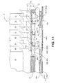
Figure 11 is an enlarged sectional view taken substantially along line 11 - 11 ofFig. 10 depicting a mailpiece being processed beneath/by the print head assembly and the runners engaging the mailpiece to maintain a desired stand-off dimension between the print head assembly nozzles and the face surface of each mailpiece. -
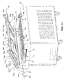
Figure 12 depicts a perspective view of a pivotable support/instrumentation rack operative to support the print head assembly with respect to the underlying compliant conveyance system and mount a variety of instrumentation, e.g., photocells/position sensors, for monitoring the progress and condition of mailpieces being processed. -
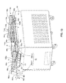
Figure 13 depicts the support/instrumentation rack pivoted to a closed position and secured by a pair of locking mechanisms to the top deck of a housing structure. - The invention is described in the context of a printing module and underlying conveyance system for a mailpiece inserter, though it will be appreciated that the system and method described herein is applicable to processing variable thickness mailpieces which are fed consecutively. Furthermore, the system and method of the present invention is applicable to mailpieces wherein a face surface thereof is disposed in register and guided along a registration plate during processing. For example, such registration may be required when inspecting a mailpiece, reading postage indicia or interpreting scan codes on the face of a mailpiece. Consequently, the detailed description and illustrations are merely indicative of an embodiment of the invention and the invention should be broadly interpreted in accordance with the appended claims.
-
Figs. 1 and2 depict perspective and top views of aprint head assembly 8 disposed over acompliant conveyance system 10. Thecompliant conveyance system 10 is operative to processmailpieces 14 which vary in thickness from about 0.10 inches to about 0.5 inches. In one embodiment of thecompliant conveyance system 10, acompliant deck 12 is provided having a low characteristic stiffness in a direction parallel to the feed path FP of mailpieces being processed and a high characteristic stiffness in a direction orthogonal to the feed path. That is, the characteristic stiffness parallel to the feed path is lower (i.e., 50% or more) than the characteristic stiffness in the orthogonal direction. - The
compliant conveyance system 10 is adapted for operation with a bank ofprint heads 16 arranged in a staggered or stepped array. Furthermore, the bank ofprint heads 16 includes a registration/skid plate 18 having acontact surface 18S for registering a first surface 14FS of eachmailpiece 14. A pivotable support/instrumentation rack (not shown in the subject illustrations) supports theprint head module 8, to maintain the position of theprint heads 16 relative to the underlying compliant conveyance system, i.e., a clearance gap therebetween. The support/instrumentation rack will be discussed in greater detail hereinafter. - The
compliant conveyance system 10 includes at least oneconveyor belt 20 having adrive surface 20S which is adapted to oppose thecontact surface 18S of theregistration plate 18. In the illustrated embodiment, thecompliant conveyance system 10 employs three (3)belts belts 20 may be employed. InFigs. 1 ,2 and3 , theconveyor belts 20 rotate around a plurality of rollers, e.g., end turn-around rollers tensioning rollers 26, 28 (seeFig. 3 ) and drive rollers (not shown) which are driven by a drive motor (also not shown). Theend rollers side beam members side beam members upper flange Figs. 1 and3 ) projects outwardly away from theconveyor belts 20 and alower flange Fig. 3 ) projects inwardly toward theconveyor belts 20. Furthermore, theweb beam members apertures flexible tubes 34 employed in a Flexible Manifold Vacuum System 50 (described in greater detail hereinbelow). - The
compliant deck 12 is disposed beneath and supports theconveyor belts 20. InFigs 3 ,4 and5 , thecompliant deck 12 comprises at least one continuous, i.e., uninterrupted, layer of a high-modulus, low-friction, high yield strength material such as a polished spring steel. In the described embodiment, thecompliant deck 12 includes asupport layer 40S (seeFigs 4 ,5 and6 ) of spring steel and asurface layer 40T of Teflon® ("Teflon" is a registered trademark of the Dupont Nemours Corporation located in Wilmington, state of Delaware) or Poly-Tetra-Flora-Ethylene (PFTE). Thesupport layer 40S spring steel has a thickness dimension T1 (seeFig. 6 ) of between about 0.010 inches to 0.015 inches, a Young's Modulus (e) of between about 2 x 10⁵ MPa to about 2.2 x 10⁵ MPa, an elongation (s) of between about 6% to about 8%, and a Yield strength (σ) of between about 1100 MPa to about 1300 MPa. Thesurface layer 40T of PFTE has a thickness dimension T2 (seeFig. 6 ) of between about 0.058 inches to 0.072 inches, a Young's Modulus (e) of between about 400 MPa to about 800 MPa, an elongation of between about 300% to 600% and a friction coefficient (κ) of less then about 0.15. The characteristic stiffness of thecompliant deck 12, i.e., the combinedlayers compliant deck 12 in a direction orthogonal to the feed path. - The
support layer 40S dominates the flexure and stiffness of thecompliant deck 12 due to the high modulus, high yield strength of spring steel. As a result, the bending neutral axis of thecompliant deck 12, i.e., the combinedlayers support layer 40S. Despite the much larger thickness dimension of thePFTE layer 40T and its distance from the bending neutral axis, its contribution to the overall stiffness of thecompliant deck 12 is negligible due to the high elongation, low modulus of thePFTE layer 40T. Consequently, thecompliant deck 12 may also be characterized as a combination oflayers deck 12, i.e., proximal to the bending neutral axis, and a high elongation, low friction material at a free edge of thedeck 12, i.e., an edge which is distal from the core and parallel thereto. This characterization of thecompliant deck 12 will be more clearly understood when discussing the thickness requirements of the Flexible Vacuum Manifold system hereinafter. - Both the support and surface layers 40S, 40T are disposed between the
side beam members forward flanges 40F which mount to a cross beam member 36 (seeFig. 3 ) disposed immediately downstream of the forward turn-aroundroller 22. Additionally,edge retention strips Fig. 5 ) are affixed to theupper flanges side beam members peripheral edge 12E (seeFig. 5 ) of thecompliant deck 12 i.e., over thesurface layer 40T thereof. - In
Figs. 3 ,4 and5 , thecompliant deck 12 is supported by aspring biasing device 42 comprising a plurality oftransverse stiffening members 44 andspring biasing members 46. More specifically, each transverse stiffeningmember 44 has a generally L-shape and is disposed beneath and across thesupport layer 40S of thecompliant deck 12, i.e., orthogonal to thecompliant belts 20. Furthermore, the stiffeningmembers 44 are disposed at regular intervals, i.e., are evenly spaced across the underside of thesupport layer 40S of thecompliant deck 12. In the described embodiment, the stiffeningmembers 44 are disposed at intervals of between one (1) to two (2) inches. Aflange portion 44F of each stiffeningmember 44 abuts the underside of thesupport layer 40S while astiffening portion 44S projects downwardly to increase the stiffness of thesupport layer 40S in a direction orthogonal to the feed path FP (shown as a point going into the plane of the drawing sheet inFig. 5 ) of theconveyance system 20. Eachend 44E of a stiffeningmember 44, i.e., along the upper surface of theflange portion 44F, is affixed to the underside peripheral edge 40SE of thesupport layer 40S. - Pairs of
spring biasing members 46 support eachend 44E of arespective stiffening member 44 and, due to the structural integration of the stiffeningportion 44S, function to provide a vertical spring biasing force across the width, i.e., orthogonal to the feed path, of thecompliant deck 12. Eachspring biasing member 46 is disposed between the underside of theflange portion 44F of arespective stiffening member 44 and the inwardly projectingflanges side beam members -
Fig. 6 depicts an enlarged view of thecompliant deck 12 when conveying consecutive thin and thick mailpieces 14TN, 14TK. The mailpieces 14TN, 14TK are aligned along an upper face or first surface 14FS against theregistration surface 18S of theregistration plate 18. Furthermore, friction forces, (forces developed along and between the lower face or second surface 14SS of themailpiece 14 and the conveyor belts 20), convey the mailpieces 14TN, 14TK beneath and passed the nozzles of the print heads 16. Asmailpieces 14 move beneath theprint module 8, the underlyingcompliant deck 12 undulates in a wave-like manner. The highlyresilient support layer 40S of spring steel flexes vertically downward to accommodate the thickness dimension of, and thickness variations between, each of the thin and thick mailpieces 14TN, 14TK. - Registration against the
plate 18 is maintained by vertical forces imposed by thespring biasing device 42. The vertical forces originate with each pair ofspring members 46 at the proximal ends 44E of each stiffeningmember 44 and are conveyed in a substantially uniform manner across thecomplaint deck 12. That is, the each stiffeningmember 44 transfers the downward motion of each mailpiece, i.e., at the center of thecompliant deck 12, to theperipheral edges 44E, where thespring biasing members 46 impose a vertical force in a direction opposing the downward displacement. Furthermore, thespring biasing device 42 may be viewed as a collection of independently operating springs which define a plurality of discrete rows. That is, the stiffeningmember 44 may be viewed as a substitute for additional spring members disposed across the width of thecompliant deck 12. As such, the regions between the stiffeningmembers 44 are soft and compliant to facilitate vertical displacement of each mailpiece. In the described embodiment, thecompliant deck 12 andspring biasing device 42 accommodates up to about one-half (1/2) inches of displacement. While thesupport layer 40S is highly compliant, the use of a high yield strength spring steel prevents plastic deformation of thecompliant deck 12, and can perform millions of cycles without failure. - The spring rate constant of each
spring member 46 is principally a function of the desired vertical deflection of thecompliant deck 12, the number oftransverse stiffening members 44, and the stiffness of thesupport layer 40S of spring steel. Secondary considerations relate to the tension loads applied to thecompliant belts 20 and the mass of the flexible vacuum conveyance/manifold system 50 which is structurally integrated with thespring biasing device 42. As a general rule, the vertical forces imposed by thespring members 46 are sufficiently high to maintain the mailpieces 14TN, 14TK against theregistration plate 18, yet sufficiently low to prevent damage to the upper face surface 14FS of each mailpiece14. - While the
compliant conveyance system 10 of the present invention includes aspring biasing device 42 including a plurality of coil springs 46, it will be appreciated that other devices or materials may be employed to provide the requisite spring rate. For example, a high elongation elastomer rubber (not shown) may be disposed between thetransverse stiffening members 44 and the support platform, i.e., the flange portion of theside beam members support layer 40S and an underlying support. - In summary, the combination of continuous support and surface layers 40S, 40T, i.e., without breaks or segments, along with a spring biasing device which imparts anisotropic stiffness properties to the compliant deck 12 (low stiffness properties parallel to the feed path and high stiffness properties orthogonal thereto), significantly enhances the fatigue life of the
conveyance system 10. Furthermore, the high degree of compliance enables processing of consecutive thin and thick mailpieces. That is, thecompliant deck 12 is capable of processing mailpieces 14TN, 14TK up to one-half inches (1/2") in thickness. Moreover, throughput, i.e., the number of mailpieces processed per unit of time, increases inasmuch as mailpieces 14TN, 14TK, whether or not disparate in thickness, may be closely spaced, i.e., between four (4) to six (6) inches apart. - The following discusses the functional and structural interaction of the
compliant deck 12 and the flexible vacuum conveyance/manifold system 50. It will be appreciated that, while the teachings associated with each are separate and distinct, the systems are structurally integrated and interdependent. - In
Figs. 4 ,7 and8 , the flexible vacuum conveyance/manifold system 50 is operative to produce a pressure differential across eachmailpiece 14 to urge the lower face or second surface 14SS of eachmailpiece 14 into frictional engagement with the upper drive surfaces 20D (seeFig. 8 ) of thecompliant belts 20. More specifically, the flexible vacuum conveyance/manifold system 50 is adapted to accommodate the motion of thecompliant deck 12 without increasing or affecting the stiffness and/or mass properties thereof. With respect to the latter, the fatigue life of the compliant deck 12 (i.e., particular the spring biasing device 42) is a function of its mass. Accordingly, an objective of the vacuum conveyance/manifold system 50 is to minimize the weight added to thecompliant conveyance system 10. - The flexible vacuum conveyance/
manifold system 50 comprises:, a plurality ofapertures 52 disposed in at least one of theconveyor belts 20, a plurality ofapertures 54, 56 (seeFigs. 4 and8 ) disposed in thecompliant deck 12 and in fluid communication with theapertures 52 of the at least oneconveyor belt 20, a plurality ofapertures 44A (seeFig. 8 ) disposed in theflange portion 44F of the stiffeningmember 44 and in fluid communication with theapertures compliant deck 12, a linear plenum 58 (seeFigs. 7 and8 ) disposed in combination with each of thestiffening members 44 and in fluid communication with theapertures 44A of therespective stiffening member 44, (Fig. 8 ), a plurality flexible vacuum tubes 34 (seeFigs. 7 and8 ) disposed in fluid communication with eachlinear plenum 58, avacuum manifold 60 disposed in fluid communication with the plurality offlexible vacuum tubes 34, and avacuum source 62 disposed in fluid communication with thevacuum manifold 60. - In the described embodiment, the
central conveyor belt 20b includes rows ofapertures 52 which are aligned withelongate slots 54 formed in thesurface layer 40T of thecompliant deck 12. Theelongate slots 54 are disposed over, and are aligned with, rows ofapertures 56 disposed through thesupport layer 40S, i.e., the sheet of spring steel, of thecompliant deck 12. Furthermore, rows ofapertures 44A are aligned with theapertures 56 of thesupport layer 40S to permit airflow through theflange portion 44F of the stiffeningmember 44. Eachlinear plenums 58 defines aplenum chamber 66 which is disposed over, and in fluid communication with, bothapertures 44 formed in the stiffeningmember 44. Theflexible tubing 34 provides a flexible path from eachplenum chamber 66 to thevacuum manifold 60. WhileFigs. 4 and7 do not show the flow through thevacuum manifold 60, it will be appreciated that thevacuum manifold 60 may vary in diameter or provide multiple flow paths to ensure relatively constant flow/pressure to each of theplenum chambers 66. - In operation, the
vacuum source 62 draws a vacuum which initiates fluid flow through thevacuum manifold 60, through the system offlexible tubing 34 and into theplenum chambers 66 of eachlinear plenum 58. The pressure differential established by thevacuum source 62 in each of thelinear plenums 58 effects fluid flow through theapertures 52 of thecentral conveyor belt 20b, through theelongate slots 54 of theupper surface layer 40T and the alignedapertures support layer 40S and the stiffeningmember 44. As theconveyor belt 20b slides over thesurface layer 40T, the eachaperture 52 of theconveyor belt 20b remains in fluid communication with at least one of theelongate slots 54 inasmuch theslots 54 span severalconveyor belt apertures 52. Consequently, all of theapertures 52 are operative to produce a pressure differential along thedrive surface 20D of thebelt 20b and across eachmailpiece 14, wherever themailpiece 14 may be located. - To accommodate the motion of the
compliant deck 12 and ensure adequate flexibility of thecompliant conveyance system 10, the flexible vacuum conveyance/manifold system 50 employs flexiblecorrugated tubing 34 between eachlinear plenum 58 and thevacuum manifold 60. Furthermore, the flexiblecorrugated tubing 34 extends throughoversized apertures 30A in theside beam member 30 to eliminate points of restraint with may stiffen or reduce the flexibility of the vacuum conveyance/manifold system 50. - Yet another feature of the flexible vacuum conveyance/
manifold system 50 relates to producing a robust reliable vacuum without increasing the stiffness of thecompliant deck 12. More specifically, to produce an adequate vacuum, the depth or thickness of theelongate slots 54 must remain large, e.g., greater than about 0.050 inches in thickness, to prevent theconveyor belt 20b from flexing/deforming into the aperture channel and retarding airflow in a longitudinal direction along theelongate slots 54. - To address this concern, the flexible vacuum conveyance/
manifold system 50 varies the stiffness and elongation properties of thedeck 12 to obtain the requisite thickness, i.e., thickness/height of theelongate slots 54 without adversely impacting the stiffness or flexibility of thecompliant conveyance system 10. More specifically, thecompliant deck 12 incorporates a high elongation, low modulus material in the portion of thedeck 12 which is exposed to the maximum bending strains (i.e., elements farthest from the bending neutral axis). Another property of this portion relating to the power requirements to drive theconveyor belts 20, is that the material have a characteristic low friction coefficient to facilitate sliding between thebelts 20 and thedeck 12. Additionally, thecompliant deck 12 incorporates a high yield strength, high modulus material in the portion of thedeck 12 which lies coincident with the bending neutral axis, i.e., at the core of thedeck 12. As such, in portions of thedeck 12 where a threshold thickness is required to formdeep slots 54, thedeck 12 is composed of high elongation, low modulus material, and in portions of thedeck 12 which require high strength, thedeck 12 is composed of high yield strength, high modulus material. - In the described embodiment, the
deck 12 employs multiple layers to establish the stiffness and elongation properties for the flexible vacuum conveyance/manifold system 50. Specifically, theelongate slots 54 are formed in asurface layer 40T of high elongation material such as PTFE. Accordingly, the depth/thickness of the vacuum slot is maintained without adversely impacting the overall stiffness of thecompliant deck 12. Furthermore, thesurface layer 40T of high elongation material is not affixed to theunderlying support layer 40S, i.e., not affixed along the mating interface, but relies on the vacuum pressure to maintain contact between thelayers elongate slots 54 andcircular apertures 56 of thecompliant deck 12. Thelayers compliant deck 12. While the present invention depicts a compliant deck having support and surface layers 40S, 40T, it will be appreciated that three or more layers may be employed to build the necessary thickness and depth of theelongate slots 54. - The flexible vacuum conveyance/
manifold system 50 employs lightweight polymers/plastic materials to minimize the weight/mass of thecompliant conveyance system 10. Theflexible tubing 34 is fabricated from corrugated molded plastic while the linear plenum is manufactured from a lightweight machinable phenolic block. Similarly, the PTFE is a lightweight polymer which minimizes the weight of thecompliant conveyance system 10. - In summary, the flexible vacuum conveyance/
manifold system 50 integrates with thecompliant conveyance system 10 in a manner which complements the desired stiffness properties. Flexible polymer tubing is employed facilitate motion of thecompliant deck 12. Moreover, the thickness of thesurface layer 40T is maintained to ensure that theelongate slots 54 are sufficiently deep to prevent the disruption of airflow and ability to draw a vacuum. Furthermore, the flexible vacuum conveyance/manifold system is fabricated from lightweight polymer/plastic material to reduce the mass and improve the fatigue life of thecompliant conveyance system 10. - Referring again to
Fig. 1 , thecompliant conveyance system 10, and its ability to process consecutive thin andthick mailpieces 14, presents several unique challenges with respect to the design/construction of theregistration plate 18. While prior art skid plates merely prevent a face surface of a mailpiece from contact with the print head nozzles, theregistration plate 18 according to the present invention, not only maintains a "stand-off" distance between themailpiece 14 and the print heads 16, but also provides a contact surface which presses against eachmailpiece 14, (particularly thick mailpieces 14TK). That is, asmailpieces 14 move along thedeck 12 and pass under theregistration plate 18, the spatial position of theregistration plate 18 remains fixed while thecompliant deck 12 deforms/deflects in response to the pressure applied by each passingmailpiece 14. - The vertical loads imposed on each
mailpiece 14 can present difficulties when printing, particularly when printing on a mailpiece surface which deforms under load. An example of such a mailpiece includes one which may contain material to protect the internal contents of the mailpiece (e.g., padding or bubble-wrap). It will be appreciated that when such a mailpiece passes under a registration/skid plate having a large opening, the soft compliant face surface of the mailpiece can bow inwardly, toward the print head nozzles. As a result the requisite stand-off distance is not maintained and print quality can be compromised. - In
Figs. 1 ,9 and10 , a registration plate assembly 70 (best seen inFig. 9 ) is provided for thecompliant conveyance system 10. Theregistration plate assembly 70 is adapted for use in combination with the array of print heads 16 and is operative to react vertical loads applied by themailpiece 14 during processing. Theregistration plate assembly 70 comprises: (i) a mountingplate 72 having at least oneaperture 72A therein for accepting aprint head nozzle 16N associated with each of the print heads 16, (ii) theregistration plate 18 affixed to the mountingplate 72 and having at least oneopening 18A formed therein for permitting the deposition of ink from each of theprint head nozzles 16N, theopening 18A having a width dimension WT orthogonal to the feed path of the conveyance system which is at least equal to the sum of the individual width dimensions WI associated with each of theprint head nozzles 16N, and (iii) a plurality ofrunners 76 affixed to the mountingplate 72 and aligned with the feed path FP of the conveyance system, eachrunner 76 having a blade portion disposed at a location between adjacentprint head nozzles 16N and operative to maintain a stand-off distance from a face surface of the mailpiece to one of theprint head nozzles 16N. - More specifically, in
Figs. 9 and10 , the mountingplate 72 is affixed to ahousing 78 which envelopes and supports the array of print heads 16. While the mountingplate 72 is depicted as a separate element mounted to and betweenside wall structures 78W of thehousing 78, it will be appreciated that the mountingplate 72 may be integrated with thehousing 78, i.e., function as a bottom wall or plate of thehousing 78. Accordingly, in the context used herein, the mountingplate 72 is any structure which interposes the print heads 16 and theregistration plate 18, and functions to mount other structure beneath the print heads 16 such as theregistration plate 18. - The
aperture 72A of the mountingplate 72 generally complements the shape and position of theprint head nozzles 16N, i.e., in the plane of thenozzles 16N. Whileindividual apertures 72A may be formed or machined for each of thenozzles 16N, the mounting plate employs asingle aperture 72A which accepts all of thenozzles 16N. Furthermore, theaperture 72A is stepped to accommodate the array ofprint head nozzles 16N which are staggered to provide print coverage over a large print zone. That is, as themailpiece 14 moves under the array of print heads 16, eachnozzle 16N thereof is available to print within a linear print zone, i.e., a zone equal to the width of a singleprint head nozzle 16N. Moreover, while thesingle aperture 72A essentially spans the entire length of the housing, i.e., in the direction of the mailpiece feed path FP, the width of theaperture 72A at any point along the length is only slightly larger than the width dimension WI of a singleprint head nozzle 16N. As a result, aregion 80 of the mountingplate 72 is maintained for affixing other structure to the mountingplate 72. - While the
registration plate 18 may be affixed directly to anunderside surface 72U of the mountingplate 72, theregistration plate 18 mounts to anspacer plate 82 which interposes anupper surface 18U of theregistration plate 18 and theunderside surface 72U of the mountingplate 72. Functionally, thespacer plate 82 is one of the elements employed to establish the stand-off distance between theprint head nozzles 16N and the face surface 14S of themailpiece 14. Furthermore, one or more additional spacer plates (not shown) may be substituted for, or disposed in combination with thespacer plate 82, to vary the stand-off distance between theprint head nozzles 16N and the face surface 14S of eachmailpiece 14. Occasionally, it may be necessary to vary the stand-off distance to process mailpieces having different physical properties or to accommodate the implementation of different print heads 16. Finally, thespacer plate 82 includes anopening 82A which corresponds in shape to theopening 18A of theunderlying registration plate 18. The characteristics of theregistration plate opening 18A will be discussed in greater detail in the subsequent paragraph which characteristics are also applicable to thespacer plate opening 82. - Similar to the
aperture 72A of the mounting plate, theopening 18A of theregistration plate 18 is stepped to accommodate the staggered arrangement of theprint head nozzles 16N. However, to prevent deposited ink from smearing or smudging, theopening 18A is open-ended. That is, theopening 18A is configured such that portions of theregistration plate 18 downstream of eachprint head nozzle 16N are removed. As a consequence, the width dimension of theopening 72A increases incrementally downstream of the first print head nozzle 16NF, i.e., the initial print head nozzle available to deposit ink on amailpiece 14. That is, the width dimension of theopening 72A increases by an amount equal to about the width of an individualprint head nozzle 16N. Finally, the maximum width dimension WT of theopening 18A corresponds to the downstream end portion 18DE of theregistration plate 18 and is generally equal to the sum of the width dimensions W1 associated with each of the print head nozzles16N. - While the
opening 18A of theregistration plate 18 has a stepped edge 18SE, it will be appreciated that other shapes may be employed. For example, to approximate the shape of the staggered print head array, theopening 18A may resemble a right triangle having a hypotenuse 84 which substitutes for the stepped edges 18SE of theopening 18A. Alternatively, theopening 18A may define arectangle 86, though, it is generally believed that an opening which corresponds to the size and shape of the array ofprint nozzles 16 provides optimum characteristics, e.g., prevents themailpiece 14 from catching on edges of theregistration plate assembly 70 and provides optimum print quality. - In
Figs. 9 and11 , the described embodiment of theregistration plate assembly 70 includes three (3)runners 76 which define channels within the registration andspacer plate openings runners 76 are aligned with, e.g., parallel to, the feed path FP of theconveyance system 10 and are spaced-apart evenly in a lateral direction, e.g., orthogonal to the feed path FP. Inasmuch as the length dimension L of the registration andspacer plate openings runners 76 may vary by a commensurate amount. - In
Figs. 10 and11 , eachrunner 76 has a generally L-shaped cross section and includes: (i) ablade portion 76B which projects downwardly from the mountingplate 72 and (ii) aflange portion 76F which lies in a plane parallel to theunderside surface 72U of the mountingplate 72. Theblade portion 76B has a leading edge which is curved and defines ablade edge 76E which slideably engages the face surface 14S of eachmailpiece 14. Theflange portion 76F includes a plurality of slottedapertures 76A (seeFig. 10 ) which accept a fastener 88 (seeFig. 11 ) for affixing therunner 76 to the mountingplate 72. Theapertures 76A permit a small degree of lateral adjustment such that theblade portion 76B of eachrunner 76 may be accurately positioned within the registration andspacer plate openings blade portion 76B of eachrunner 76 is aligned with one of the steps 18SE, 82SE of the registration andspacer plate openings Fig. 10 ) of eachrunner 76 is disposed aft, or downstream, of one of the steps 18SE, 82SE and/or is longitudinally aligned with a riser edge 18RE, 82RE disposed downstream of the respective step 18SE, 82SE. As such, eachrunner 76 does not interfere with ink deposited from theprint head nozzle 16N disposed upstream of therespective runner 76, i.e., the nozzle corresponding to the respective step 18SE, 82SE. - In operation, the
registration plate assembly 70 provides the necessary stand-off distance from theprint head nozzles 16N to the face surface 14FS of theunderlying mailpiece 14. Thecompliant conveyance system 10 transports themailpieces 14 to theprint head assembly 8 and, as themailpiece 14 approach the array of print heads 16, an inclined leading edge 18IE of theregistration plate 18 guides eachmailpiece 14 beneath theregistration plate 18, The inclined edge 18IE defines an angle θ of between about ten (10) degrees to about forty (40) degrees relative to the plane of thecompliant deck 12 to ensure that both thin and thick mailpieces 14TN, 14TK are accepted/ingested smoothly beneath the plate 79 and in register with thecontact surface 18S. As themailpieces 14 engage theregistration plate assembly 70, theprint head assembly 8 presses downwardly on the face surface 14FS of themailpiece 14 during processing/printing. Any tendency for themailpiece 14, i.e., the face surface 14FS, to bow upwardly toward the print head nozzles is mitigated by therunners 76. More specifically, the face surface 14FS is vertically supported by therunners 76 at locations between the stepped and opposing lateral edges 18SE, 82SE, 18LE, 82LE of the registration andspacer plate openings blade portion 76B of eachrunner 76 is aligned with, and parallel to, one of the stepped edges 18SE, 82SE, theblade edge 76E does not smear or smudge ink deposited by anupstream nozzle 16N. Theblade edge 76E contacts the face surface 14FS at a position betweennozzles 16N and does not interfere with the deposited ink, i.e., ink deposited in linear zones to each side of arunner 76. Such zones may correspond to the white space between printed lines of a destination or return address. - In
Figs. 12 and13 , theprint head assembly 8 is affixed to a pivotable support/instrumentation rack 90 to perform routine maintenance on theprint head assembly 8 and underlyingcompliant conveyance system 10. More specifically, thecompliant conveyance system 10 is disposed in combination with ahousing 92 which mounts the pivotable support/instrumentation rack 90. Thehousing 92 accepts theconveyance system 10 such that thecompliant deck 12 is essentially coplanar with atop deck 92D of thehousing 92. Thetop deck 92D includes first andsecond portions 92D-1, 92D-2 which extend outwardly from theside beam members conveyance system 10. Thefirst portion 92D-1 of thedeck 92D pivotally mounts the support/instrumentation rack 90 about anaxis 90A while thesecond portion 92D-2 of thetop deck 92D mounts a pair of lockingmechanisms - The support/
instrumentation rack 90, furthermore, includes a pair ofstructural longerons conveyance system 10 and a plurality of stiffeningribs longerons gas springs housing 92 and a pair of thestiffening ribs support instrumentation rack 90 about thepivot axis 90A. More specifically, thegas springs axis 90A to bias the support/instrumentation rack 90 upwardly, i.e., to an open position. Furthermore, the support/instrumentation rack 90 may be moved to a closed position by imposing a clockwise moment M2 about theaxis 90A (i.e., a vertically downward force F applied by an operator). The closed position is achieved when a pair ofhigh tolerance feet outboard longeron 100b, abut each of the lockingmechanisms anvil portion 104 of each of the lockingmechanisms feet instrumentation rack 90 against the upward biasing force of thegas springs - The
print head assembly 8 is mounted to one of thestiffening ribs instrumentation rack 90 is closed, the print head andregistration plate assemblies underlying conveyance system 10. In addition to mounting theprint head assembly 8, the stiffeningribs photocells photocells mailpiece 14 asmailpieces 14 are conveyed along thecompliant deck 12. Sensors (not shown) disposed beneath thedeck 12 receive a beam of light through apertures 112 (seeFig. 2 ) in the compliant deck. - The pivotable support/
instrumentation deck 90 facilitates access to theprint head assembly 8 and underlyingcompliant conveyance system 10. When thelocking assemblies 102a, 192b are released, the support/instrumentation deck 90 immediately rotates to the open position under the force of thegas springs photocells - It is to be understood that all of the present figures, and the accompanying narrative discussions of preferred embodiments, do not purport to be completely rigorous treatments of the methods and systems under consideration. For example, while the invention describes an interval of time for completing a phase of sorting operations, it should be appreciated that the processing time may differ. A person skilled in the art will understand that the steps of the present application represent general cause-and-effect relationships that do not exclude intermediate interactions of various types, and will further understand that the various structures and mechanisms described in this application can be implemented by a variety of different combinations of hardware and software, methods of escorting and storing individual mailpieces and in various configurations which need not be further elaborated herein.
Claims (18)
- A system for processing mailpiece (14), comprising:a registration plate (18) having a contact surface (18S) for registering a first surface (14FS) of each of the mailpieces (14);at least one conveyor belt (20) opposing the contact surface (18S) of the registration plate (18) and rotatable around a plurality of rollers (22,24), the conveyor belt (20) having a drive surface (20S) for engaging a second surface (14SS) of each of the mailpieces for conveyance along the feed path (FP); anda compliant deck (12) disposed beneath and supporting an underside surface of the at least one conveyor belt (20); anda spring biasing device (42) operative to bias the compliant deck (12) and the at least one conveyor belt (20) toward the contact surface of the registration plate (18) such that the second surface of each of the mailpieces is urged into engagement with the contact surface (18S) during processing.
- The system according to claim 1 further comprising at least one print head assembly (8) having a print nozzle (16N) for depositing ink, and wherein the registration plate includes an opening (18A) aligned with the print nozzle (16N) to permit printing on the first surface (14FS) of each of the mailpieces (14) as each is conveyed along the feed path.
- The system according to claim 1 or 2 wherein the complaint deck (12) is a flexible metal sheet having a characteristic stiffness in directions parallel and orthogonal to the feed path (FP), the characteristic stiffness parallel to the feed path being less than the characteristic stiffness orthogonal to the feed path (FP).
- The system according to claim 3 wherein the characteristic stiffness parallel to the feed path (FP) is about two-hundred percent (200%) to about four hundred percent (400%) of the characteristic stiffness of the compliant deck (12) in a direction orthogonal to the feed path.
- The system according to any preceding claim wherein the compliant deck (12) includes a surface layer (40T) and a support layer (40S) disposed beneath and supporting the surface layer, the surface and support layers each having a characteristic yield strength and a characteristic elongation property, the surface layer (40T) having a higher characteristic elongation property than the characteristic elongation property of the support layer (40S), and the support layer having a higher characteristic yield strength than the characteristic yield strength of the surface layer.
- The system according to any preceding claims further comprising a structural platform (32) disposed beneath the compliant deck (12) and a plurality of independent coil springs (46) each having one end connected to the underside surface of the compliant deck and the other end connected to the support platform.
- The system according to claim 5 wherein the spring biasing device (42) includes a structural platform (32) disposed beneath the compliant deck (12) and a plurality of independent coil springs (46) each having one end connected to the underside surface of the compliant deck (12) and the other end connected to the support platform (32), the coil springs defining a plurality of aligned rows disposed between the elongate plenums.
- The system according to any preceding claims wherein the compliant deck (12) includes multiple layers defining a sliding interface between adjacent layers.
- The system according to any preceding claim wherein the spring biasing device (42) includes a structural platform (32) disposed beneath the compliant deck (12) and a resilient foam disposed between the compliant deck and the structural platform.
- A method for conveying mailpieces (14) along a feed path (FP) and registering the mailpieces during processing, comprising the steps of:receiving the mailpieces (14) in a transport system, the transport system including:a registration plate (18) having a contact surface (18S) for registering a first surface (14FS) of each of the mailpieces (14);at least one conveyor belt (20) opposing the contact surface (18S) of the registration plate (18) and rotatable around a plurality of drive rollers (22,24), the conveyor belt (20) having a drive surface (20S) for engaging a second surface (14SS) of each of the mailpieces (14) for conveyance along the feed path (FP); anda compliant deck (12) disposed beneath and supporting an underside surface of the at least one conveyor belt (20);developing a pressure differential across each of the mailpieces (14) to urge the second surface into frictional engagement with the drive surface of the at least one conveyor belt (20);conveying the mailpieces (14) along the feed path, andmaintaining the mailpieces (14) in registration the contact surface of the registration plate (18) by a spring biasing device (42) disposed beneath the compliant deck (18);the spring biasing device (42) biasing the compliant deck (18) and conveyor belt (20) toward the contact surface of the registration plate (18) such that the second surface of each of the mailpieces (14) is urged into engagement with the contact surface (18S).
- The method of claim 10, further comprising the step of biasing the compliant deck (18) to provide registration of consecutive mailpieces having a thickness differential of up to about 1.75 inches.
- The method according to claim 10 or 11 further comprising the step of: providing an opening (18A) in the registration plate (18) and printing on the first surface (14FS) by depositing ink through the opening in the registration plate (18).
- The method according to claim 10, 11 or 12, including the step of fabricating the compliant deck (18), to define a characteristic stiffness in directions parallel and orthogonal to the feed path, the characteristic stiffness parallel to the feed path being less than the characteristic stiffness orthogonal to the feed path.
- The method according to claim 13 wherein the characteristic stiffness parallel to the feed path (FP) is about two-hundred percent (200%) to about four hundred percent (400%) of the characteristic stiffness of the compliant deck (18) in a direction orthogonal to the feed path.
- The method according to any one of claims 10 to 14 wherein the compliant deck (18) includes a surface layer and a support layer disposed beneath and supporting the surface layer, the surface and support layer each having a characteristic yield strength and a characteristic elongation property, the surface layer having a higher characteristic elongation property than the characteristic elongation property of the support layer, and the support layer having a higher characteristic yield strength than the characteristic yield strength of the surface layer.
- The method according to claim 15 wherein the step of biasing the compliant deck (18) includes the steps of: providing a structural platform (32) beneath the compliant deck (18), and providing a plurality of coil springs (46) between the structural platform (32) and the compliant deck (18) in areas between elongate plenums (58).
- The method according to any of claims 10 to 16 wherein the compliant deck (18) includes multiple layers defining a sliding interface between adjacent layers.
- The method according to any of claims 10 to 17 wherein the step of biasing the compliant deck (18) includes the steps of providing a structural platform (32) beneath the compliant deck (18), and providing a resilient foam between the compliant deck and the structural platform.
Applications Claiming Priority (1)
| Application Number | Priority Date | Filing Date | Title |
|---|---|---|---|
| US12/380,706 US8123023B2 (en) | 2009-03-02 | 2009-03-02 | Mailpiece conveyance system |
Publications (2)
| Publication Number | Publication Date |
|---|---|
| EP2226199A1 true EP2226199A1 (en) | 2010-09-08 |
| EP2226199B1 EP2226199B1 (en) | 2018-05-23 |
Family
ID=42144991
Family Applications (1)
| Application Number | Title | Priority Date | Filing Date |
|---|---|---|---|
| EP10153433.7A Not-in-force EP2226199B1 (en) | 2009-03-02 | 2010-02-12 | Mailpiece conveyance system and method |
Country Status (3)
| Country | Link |
|---|---|
| US (1) | US8123023B2 (en) |
| EP (1) | EP2226199B1 (en) |
| CA (1) | CA2692352A1 (en) |
Families Citing this family (8)
| Publication number | Priority date | Publication date | Assignee | Title |
|---|---|---|---|---|
| DE102010049258A1 (en) * | 2010-10-25 | 2012-04-26 | Wemhöner Surface GmbH & Co. KG | Device for digital printing of planar workpiece e.g. thin board, has low pressure box with passage apertures, which is connected to low pressure device over connection tubes |
| JP6036590B2 (en) * | 2013-07-25 | 2016-11-30 | 富士ゼロックス株式会社 | Belt offset control structure, transfer device, and image forming apparatus |
| EP3156245B1 (en) * | 2015-09-28 | 2020-08-19 | Halm Industries Co., Inc. | Vacuum transfer device for envelope printer |
| DE102016117994A1 (en) * | 2016-09-23 | 2018-03-29 | Karl Heesemann Maschinenfabrik Gmbh & Co. Kg | grinding machine |
| DE102016117992A1 (en) * | 2016-09-23 | 2018-03-29 | Karl Heesemann Maschinenfabrik Gmbh & Co Kg | grinding machine |
| DE102016117991A1 (en) * | 2016-09-23 | 2018-03-29 | Karl Heesemann Maschinenfabrik Gmbh & Co Kg | grinding machine |
| US10350641B1 (en) * | 2016-12-20 | 2019-07-16 | Bryan Chevalier Nelson Watson | Vacuum system |
| EP3859688A1 (en) * | 2020-01-29 | 2021-08-04 | Neopost Technologies | Envelope printing device |
Citations (5)
| Publication number | Priority date | Publication date | Assignee | Title |
|---|---|---|---|---|
| US5488399A (en) | 1990-10-12 | 1996-01-30 | Canon Kabushiki Kaisha | Belt driving apparatus and image recording apparatus using the same |
| FR2766757A1 (en) * | 1997-08-01 | 1999-02-05 | Secap | Image printing device for franking machine |
| US6254092B1 (en) * | 2000-04-17 | 2001-07-03 | Hewlett-Packard Company | Controlling vacuum flow for ink-jet hard copy apparatus |
| US20020085871A1 (en) * | 2000-12-28 | 2002-07-04 | Salomon James A. | Method and system for transporting mailpieces in a printing station |
| EP1431925A2 (en) | 2002-12-19 | 2004-06-23 | Pitney Bowes Inc. | Transport mechanism for a mailing machine and method to register a mail piece in a mailing machine |
Family Cites Families (11)
| Publication number | Priority date | Publication date | Assignee | Title |
|---|---|---|---|---|
| US3386565A (en) * | 1965-10-20 | 1968-06-04 | Meyer Geo J Mfg Co | Hold-down belt for labeling machines |
| US3422732A (en) * | 1966-08-15 | 1969-01-21 | Ruth S York | Artificial ski mat |
| US3521322A (en) * | 1967-03-08 | 1970-07-21 | Nordischer Maschinenbau | Conveyor belt for gripping and carrying fish |
| US3468409A (en) * | 1967-10-23 | 1969-09-23 | Phillips Petroleum Co | Puller |
| US4447817A (en) * | 1982-09-27 | 1984-05-08 | Xerox Corporation | Constant velocity copy sheet transport with ink jet printing |
| US4719721A (en) * | 1986-12-18 | 1988-01-19 | Timesavers, Inc. | Conveyor bed assembly and vacuum platen |
| US5943081A (en) * | 1988-12-30 | 1999-08-24 | Canon Kabushiki Kaisha | Image recording apparatus |
| US5342133A (en) * | 1992-12-23 | 1994-08-30 | Hewlett-Packard Company | Paper moving system for a printer/plotter |
| US5466329A (en) * | 1994-06-03 | 1995-11-14 | Marquip, Inc. | Adjustable ballast system for the holddown belt in a double facer |
| US5847382A (en) * | 1996-10-22 | 1998-12-08 | Jay Koch | Bone detector |
| FR2790997B1 (en) * | 1999-03-16 | 2001-06-01 | Secap | DEVICE FOR PRINTING A SIGN AND MACHINE FOR POSTAGE THE BEARING |
-
2009
- 2009-03-02 US US12/380,706 patent/US8123023B2/en not_active Expired - Fee Related
-
2010
- 2010-02-08 CA CA2692352A patent/CA2692352A1/en not_active Abandoned
- 2010-02-12 EP EP10153433.7A patent/EP2226199B1/en not_active Not-in-force
Patent Citations (5)
| Publication number | Priority date | Publication date | Assignee | Title |
|---|---|---|---|---|
| US5488399A (en) | 1990-10-12 | 1996-01-30 | Canon Kabushiki Kaisha | Belt driving apparatus and image recording apparatus using the same |
| FR2766757A1 (en) * | 1997-08-01 | 1999-02-05 | Secap | Image printing device for franking machine |
| US6254092B1 (en) * | 2000-04-17 | 2001-07-03 | Hewlett-Packard Company | Controlling vacuum flow for ink-jet hard copy apparatus |
| US20020085871A1 (en) * | 2000-12-28 | 2002-07-04 | Salomon James A. | Method and system for transporting mailpieces in a printing station |
| EP1431925A2 (en) | 2002-12-19 | 2004-06-23 | Pitney Bowes Inc. | Transport mechanism for a mailing machine and method to register a mail piece in a mailing machine |
Also Published As
| Publication number | Publication date |
|---|---|
| CA2692352A1 (en) | 2010-09-02 |
| US20100219041A1 (en) | 2010-09-02 |
| US8123023B2 (en) | 2012-02-28 |
| EP2226199B1 (en) | 2018-05-23 |
Similar Documents
| Publication | Publication Date | Title |
|---|---|---|
| US8182083B2 (en) | Print module having pivotable support/instrumentation rack for print head assembly | |
| EP2226199B1 (en) | Mailpiece conveyance system and method | |
| US8083222B2 (en) | Stacking apparatus, transportation apparatus and recording apparatus | |
| EP2226279B1 (en) | Vacuum conveyance system | |
| CA1306896C (en) | Ink-jet printhead-to-paper referencing system | |
| US8899742B2 (en) | Image recording apparatus | |
| US8186787B2 (en) | Method and apparatus for printing on variable thickness print media | |
| US6651974B2 (en) | Sheet feed apparatus and recording apparatus equipped with sheet feed apparatus | |
| EP0595321B1 (en) | Sheet convey apparatus | |
| EP2226197B1 (en) | Registration plate assembly for mailpiece conveyance system | |
| US20060157911A1 (en) | Sheet feed apparatus | |
| US7611141B2 (en) | Top registered item transport system | |
| US7810810B2 (en) | Apparatus for pressing flat materials onto a transport module | |
| US8500345B2 (en) | Item handling system with printer alignment | |
| US6883909B2 (en) | Printing apparatus which prevents floating of a recording sheet | |
| US8328444B2 (en) | Apparatus and method for printing on irregular surfaces | |
| US7419243B2 (en) | Device for conveying and guiding mail items | |
| US6976801B2 (en) | Method and system for transporting mailpieces in a printing station | |
| US8215629B2 (en) | System and method for producing and arranging sheet material for use in a mailpiece inserter | |
| US8531699B2 (en) | Item transport system with pneumatic aligner | |
| US11565536B2 (en) | Envelope printing device | |
| US20100059335A1 (en) | Transporting apparatus for web products and related methods | |
| IT202200024573A1 (en) | Method for aligning cards in a card printing plant |
Legal Events
| Date | Code | Title | Description |
|---|---|---|---|
| PUAI | Public reference made under article 153(3) epc to a published international application that has entered the european phase |
Free format text: ORIGINAL CODE: 0009012 |
|
| AK | Designated contracting states |
Kind code of ref document: A1 Designated state(s): AT BE BG CH CY CZ DE DK EE ES FI FR GB GR HR HU IE IS IT LI LT LU LV MC MK MT NL NO PL PT RO SE SI SK SM TR |
|
| AX | Request for extension of the european patent |
Extension state: AL BA RS |
|
| 17P | Request for examination filed |
Effective date: 20110307 |
|
| 17Q | First examination report despatched |
Effective date: 20160329 |
|
| GRAP | Despatch of communication of intention to grant a patent |
Free format text: ORIGINAL CODE: EPIDOSNIGR1 |
|
| STAA | Information on the status of an ep patent application or granted ep patent |
Free format text: STATUS: GRANT OF PATENT IS INTENDED |
|
| INTG | Intention to grant announced |
Effective date: 20180205 |
|
| GRAS | Grant fee paid |
Free format text: ORIGINAL CODE: EPIDOSNIGR3 |
|
| GRAA | (expected) grant |
Free format text: ORIGINAL CODE: 0009210 |
|
| STAA | Information on the status of an ep patent application or granted ep patent |
Free format text: STATUS: THE PATENT HAS BEEN GRANTED |
|
| AK | Designated contracting states |
Kind code of ref document: B1 Designated state(s): AT BE BG CH CY CZ DE DK EE ES FI FR GB GR HR HU IE IS IT LI LT LU LV MC MK MT NL NO PL PT RO SE SI SK SM TR |
|
| REG | Reference to a national code |
Ref country code: GB Ref legal event code: FG4D |
|
| REG | Reference to a national code |
Ref country code: CH Ref legal event code: EP |
|
| REG | Reference to a national code |
Ref country code: IE Ref legal event code: FG4D |
|
| REG | Reference to a national code |
Ref country code: AT Ref legal event code: REF Ref document number: 1001198 Country of ref document: AT Kind code of ref document: T Effective date: 20180615 |
|
| REG | Reference to a national code |
Ref country code: DE Ref legal event code: R096 Ref document number: 602010050732 Country of ref document: DE |
|
| REG | Reference to a national code |
Ref country code: NL Ref legal event code: MP Effective date: 20180523 |
|
| REG | Reference to a national code |
Ref country code: LT Ref legal event code: MG4D |
|
| PG25 | Lapsed in a contracting state [announced via postgrant information from national office to epo] |
Ref country code: SE Free format text: LAPSE BECAUSE OF FAILURE TO SUBMIT A TRANSLATION OF THE DESCRIPTION OR TO PAY THE FEE WITHIN THE PRESCRIBED TIME-LIMIT Effective date: 20180523 Ref country code: FI Free format text: LAPSE BECAUSE OF FAILURE TO SUBMIT A TRANSLATION OF THE DESCRIPTION OR TO PAY THE FEE WITHIN THE PRESCRIBED TIME-LIMIT Effective date: 20180523 Ref country code: BG Free format text: LAPSE BECAUSE OF FAILURE TO SUBMIT A TRANSLATION OF THE DESCRIPTION OR TO PAY THE FEE WITHIN THE PRESCRIBED TIME-LIMIT Effective date: 20180823 Ref country code: NO Free format text: LAPSE BECAUSE OF FAILURE TO SUBMIT A TRANSLATION OF THE DESCRIPTION OR TO PAY THE FEE WITHIN THE PRESCRIBED TIME-LIMIT Effective date: 20180823 Ref country code: ES Free format text: LAPSE BECAUSE OF FAILURE TO SUBMIT A TRANSLATION OF THE DESCRIPTION OR TO PAY THE FEE WITHIN THE PRESCRIBED TIME-LIMIT Effective date: 20180523 Ref country code: LT Free format text: LAPSE BECAUSE OF FAILURE TO SUBMIT A TRANSLATION OF THE DESCRIPTION OR TO PAY THE FEE WITHIN THE PRESCRIBED TIME-LIMIT Effective date: 20180523 |
|
| PG25 | Lapsed in a contracting state [announced via postgrant information from national office to epo] |
Ref country code: LV Free format text: LAPSE BECAUSE OF FAILURE TO SUBMIT A TRANSLATION OF THE DESCRIPTION OR TO PAY THE FEE WITHIN THE PRESCRIBED TIME-LIMIT Effective date: 20180523 Ref country code: GR Free format text: LAPSE BECAUSE OF FAILURE TO SUBMIT A TRANSLATION OF THE DESCRIPTION OR TO PAY THE FEE WITHIN THE PRESCRIBED TIME-LIMIT Effective date: 20180824 Ref country code: NL Free format text: LAPSE BECAUSE OF FAILURE TO SUBMIT A TRANSLATION OF THE DESCRIPTION OR TO PAY THE FEE WITHIN THE PRESCRIBED TIME-LIMIT Effective date: 20180523 Ref country code: HR Free format text: LAPSE BECAUSE OF FAILURE TO SUBMIT A TRANSLATION OF THE DESCRIPTION OR TO PAY THE FEE WITHIN THE PRESCRIBED TIME-LIMIT Effective date: 20180523 |
|
| REG | Reference to a national code |
Ref country code: AT Ref legal event code: MK05 Ref document number: 1001198 Country of ref document: AT Kind code of ref document: T Effective date: 20180523 |
|
| PG25 | Lapsed in a contracting state [announced via postgrant information from national office to epo] |
Ref country code: AT Free format text: LAPSE BECAUSE OF FAILURE TO SUBMIT A TRANSLATION OF THE DESCRIPTION OR TO PAY THE FEE WITHIN THE PRESCRIBED TIME-LIMIT Effective date: 20180523 Ref country code: PL Free format text: LAPSE BECAUSE OF FAILURE TO SUBMIT A TRANSLATION OF THE DESCRIPTION OR TO PAY THE FEE WITHIN THE PRESCRIBED TIME-LIMIT Effective date: 20180523 Ref country code: DK Free format text: LAPSE BECAUSE OF FAILURE TO SUBMIT A TRANSLATION OF THE DESCRIPTION OR TO PAY THE FEE WITHIN THE PRESCRIBED TIME-LIMIT Effective date: 20180523 Ref country code: SK Free format text: LAPSE BECAUSE OF FAILURE TO SUBMIT A TRANSLATION OF THE DESCRIPTION OR TO PAY THE FEE WITHIN THE PRESCRIBED TIME-LIMIT Effective date: 20180523 Ref country code: RO Free format text: LAPSE BECAUSE OF FAILURE TO SUBMIT A TRANSLATION OF THE DESCRIPTION OR TO PAY THE FEE WITHIN THE PRESCRIBED TIME-LIMIT Effective date: 20180523 Ref country code: EE Free format text: LAPSE BECAUSE OF FAILURE TO SUBMIT A TRANSLATION OF THE DESCRIPTION OR TO PAY THE FEE WITHIN THE PRESCRIBED TIME-LIMIT Effective date: 20180523 Ref country code: CZ Free format text: LAPSE BECAUSE OF FAILURE TO SUBMIT A TRANSLATION OF THE DESCRIPTION OR TO PAY THE FEE WITHIN THE PRESCRIBED TIME-LIMIT Effective date: 20180523 |
|
| REG | Reference to a national code |
Ref country code: DE Ref legal event code: R097 Ref document number: 602010050732 Country of ref document: DE |
|
| PG25 | Lapsed in a contracting state [announced via postgrant information from national office to epo] |
Ref country code: IT Free format text: LAPSE BECAUSE OF FAILURE TO SUBMIT A TRANSLATION OF THE DESCRIPTION OR TO PAY THE FEE WITHIN THE PRESCRIBED TIME-LIMIT Effective date: 20180523 Ref country code: SM Free format text: LAPSE BECAUSE OF FAILURE TO SUBMIT A TRANSLATION OF THE DESCRIPTION OR TO PAY THE FEE WITHIN THE PRESCRIBED TIME-LIMIT Effective date: 20180523 |
|
| PLBE | No opposition filed within time limit |
Free format text: ORIGINAL CODE: 0009261 |
|
| STAA | Information on the status of an ep patent application or granted ep patent |
Free format text: STATUS: NO OPPOSITION FILED WITHIN TIME LIMIT |
|
| PGFP | Annual fee paid to national office [announced via postgrant information from national office to epo] |
Ref country code: DE Payment date: 20190227 Year of fee payment: 10 Ref country code: GB Payment date: 20190227 Year of fee payment: 10 |
|
| 26N | No opposition filed |
Effective date: 20190226 |
|
| PG25 | Lapsed in a contracting state [announced via postgrant information from national office to epo] |
Ref country code: SI Free format text: LAPSE BECAUSE OF FAILURE TO SUBMIT A TRANSLATION OF THE DESCRIPTION OR TO PAY THE FEE WITHIN THE PRESCRIBED TIME-LIMIT Effective date: 20180523 |
|
| PGFP | Annual fee paid to national office [announced via postgrant information from national office to epo] |
Ref country code: FR Payment date: 20190225 Year of fee payment: 10 |
|
| REG | Reference to a national code |
Ref country code: DE Ref legal event code: R082 Ref document number: 602010050732 Country of ref document: DE Representative=s name: HOFFMANN - EITLE PATENT- UND RECHTSANWAELTE PA, DE Ref country code: DE Ref legal event code: R081 Ref document number: 602010050732 Country of ref document: DE Owner name: DMT SOLUTIONS GLOBAL CORP. (N.D.GES.D. STAATES, US Free format text: FORMER OWNER: PITNEY BOWES, INC., STAMFORD, CONN., US |
|
| REG | Reference to a national code |
Ref country code: CH Ref legal event code: PL |
|
| PG25 | Lapsed in a contracting state [announced via postgrant information from national office to epo] |
Ref country code: LU Free format text: LAPSE BECAUSE OF NON-PAYMENT OF DUE FEES Effective date: 20190212 Ref country code: MC Free format text: LAPSE BECAUSE OF FAILURE TO SUBMIT A TRANSLATION OF THE DESCRIPTION OR TO PAY THE FEE WITHIN THE PRESCRIBED TIME-LIMIT Effective date: 20180523 |
|
| REG | Reference to a national code |
Ref country code: BE Ref legal event code: MM Effective date: 20190228 |
|
| REG | Reference to a national code |
Ref country code: IE Ref legal event code: MM4A |
|
| REG | Reference to a national code |
Ref country code: GB Ref legal event code: 732E Free format text: REGISTERED BETWEEN 20191128 AND 20191204 |
|
| PG25 | Lapsed in a contracting state [announced via postgrant information from national office to epo] |
Ref country code: LI Free format text: LAPSE BECAUSE OF NON-PAYMENT OF DUE FEES Effective date: 20190228 Ref country code: CH Free format text: LAPSE BECAUSE OF NON-PAYMENT OF DUE FEES Effective date: 20190228 |
|
| PG25 | Lapsed in a contracting state [announced via postgrant information from national office to epo] |
Ref country code: IE Free format text: LAPSE BECAUSE OF NON-PAYMENT OF DUE FEES Effective date: 20190212 |
|
| PG25 | Lapsed in a contracting state [announced via postgrant information from national office to epo] |
Ref country code: BE Free format text: LAPSE BECAUSE OF NON-PAYMENT OF DUE FEES Effective date: 20190228 |
|
| PG25 | Lapsed in a contracting state [announced via postgrant information from national office to epo] |
Ref country code: TR Free format text: LAPSE BECAUSE OF FAILURE TO SUBMIT A TRANSLATION OF THE DESCRIPTION OR TO PAY THE FEE WITHIN THE PRESCRIBED TIME-LIMIT Effective date: 20180523 |
|
| PG25 | Lapsed in a contracting state [announced via postgrant information from national office to epo] |
Ref country code: PT Free format text: LAPSE BECAUSE OF FAILURE TO SUBMIT A TRANSLATION OF THE DESCRIPTION OR TO PAY THE FEE WITHIN THE PRESCRIBED TIME-LIMIT Effective date: 20180924 Ref country code: MT Free format text: LAPSE BECAUSE OF NON-PAYMENT OF DUE FEES Effective date: 20190212 |
|
| REG | Reference to a national code |
Ref country code: DE Ref legal event code: R119 Ref document number: 602010050732 Country of ref document: DE |
|
| GBPC | Gb: european patent ceased through non-payment of renewal fee |
Effective date: 20200212 |
|
| PG25 | Lapsed in a contracting state [announced via postgrant information from national office to epo] |
Ref country code: DE Free format text: LAPSE BECAUSE OF NON-PAYMENT OF DUE FEES Effective date: 20200901 Ref country code: GB Free format text: LAPSE BECAUSE OF NON-PAYMENT OF DUE FEES Effective date: 20200212 Ref country code: FR Free format text: LAPSE BECAUSE OF NON-PAYMENT OF DUE FEES Effective date: 20200229 |
|
| PG25 | Lapsed in a contracting state [announced via postgrant information from national office to epo] |
Ref country code: CY Free format text: LAPSE BECAUSE OF FAILURE TO SUBMIT A TRANSLATION OF THE DESCRIPTION OR TO PAY THE FEE WITHIN THE PRESCRIBED TIME-LIMIT Effective date: 20180523 |
|
| PG25 | Lapsed in a contracting state [announced via postgrant information from national office to epo] |
Ref country code: IS Free format text: LAPSE BECAUSE OF FAILURE TO SUBMIT A TRANSLATION OF THE DESCRIPTION OR TO PAY THE FEE WITHIN THE PRESCRIBED TIME-LIMIT Effective date: 20180923 |
|
| PG25 | Lapsed in a contracting state [announced via postgrant information from national office to epo] |
Ref country code: HU Free format text: LAPSE BECAUSE OF FAILURE TO SUBMIT A TRANSLATION OF THE DESCRIPTION OR TO PAY THE FEE WITHIN THE PRESCRIBED TIME-LIMIT; INVALID AB INITIO Effective date: 20100212 |
|
| PG25 | Lapsed in a contracting state [announced via postgrant information from national office to epo] |
Ref country code: MK Free format text: LAPSE BECAUSE OF FAILURE TO SUBMIT A TRANSLATION OF THE DESCRIPTION OR TO PAY THE FEE WITHIN THE PRESCRIBED TIME-LIMIT Effective date: 20180523 |