EP2225930A1 - Automatic lateral tilt control of a header in stubble height mode using a machine level sensor - Google Patents
Automatic lateral tilt control of a header in stubble height mode using a machine level sensor Download PDFInfo
- Publication number
- EP2225930A1 EP2225930A1 EP10154697A EP10154697A EP2225930A1 EP 2225930 A1 EP2225930 A1 EP 2225930A1 EP 10154697 A EP10154697 A EP 10154697A EP 10154697 A EP10154697 A EP 10154697A EP 2225930 A1 EP2225930 A1 EP 2225930A1
- Authority
- EP
- European Patent Office
- Prior art keywords
- angle
- machine
- header
- lateral tilt
- information representative
- Prior art date
- Legal status (The legal status is an assumption and is not a legal conclusion. Google has not performed a legal analysis and makes no representation as to the accuracy of the status listed.)
- Granted
Links
Images



Classifications
-
- A—HUMAN NECESSITIES
- A01—AGRICULTURE; FORESTRY; ANIMAL HUSBANDRY; HUNTING; TRAPPING; FISHING
- A01D—HARVESTING; MOWING
- A01D75/00—Accessories for harvesters or mowers
- A01D75/28—Control mechanisms for harvesters or mowers when moving on slopes; Devices preventing lateral pull
- A01D75/287—Control mechanisms for harvesters or mowers when moving on slopes; Devices preventing lateral pull acting on the mowing table
Definitions
- This invention relates generally to a system and method for controlling the angle of lateral tilt of a header of an agricultural plant cutting machine, such as, but not limited to, a combine, windrower or the like, when disposed on a laterally inclined surface and more particularly, to an automatic lateral tilt control system which precisely controls an angle of lateral tilt of the header relative to the machine based on a lateral tilt angle of the machine relative to a reference and at least one additional characteristic.
- an agricultural plant cutting machine such as, but not limited to, a combine, windrower or the like
- Agricultural plant cutting and harvesting machines typically have a header which is desired or required to be positioned at one or more selectable cutting heights in relation to the surface, and at angles of sideward tilt in relation to the machine itself, as well as to a surface over which the machine is driven. Such capability is illustrated in AU-B-548902 .
- a header When the header is positioned at a cutting height above the surface, such that the stalks of crops are left at a higher level, the machine is operating in what is sometimes referred to as a "stubble mode".
- Conventional ground sensing capability as in US-A-6,523,333 , is generally only useful when the header is positioned very close to, or on, the surface. Thus typical ground sensing capability, if present at all, is unavailable or inoperable when the machine is operating in the stubble mode.
- the height difference at the ends of the header may not present a problem.
- this angular difference causes a more pronounced height difference at the ends of the header such that the downhill side of the header may ride significantly closer to the surface than the uphill side. In some circumstances, this may lead to undesirably uneven cutting height and risks possible damage to the cutting apparatus due to impact with the ground. In this situation an operator typically provides an uphill tilt correction to compensate for the undesired sideward or transverse tilt angle of the header.
- automatic lateral tilt control system for a header of an agricultural plant cutting machine, comprising:
- a method for automatically controlling the lateral tilt of a header of an agricultural plant cutting machine comprising:
- the invention uses the lateral tilt angle of the machine provided by the inclinometer and an additional characteristic to model or predict the lateral tilt angle of the inclined surface so as to provide automatic compensation of the header tilt angle to maintain desired cutting height, thereby reducing the possibility of damage to the cutting apparatus of the header, and reducing operator workload.
- the system includes at least one driver in connection with the header configured so as to be controllably operable by a header tilt command input for varying an angle of lateral tilt of the header relative to the machine, and a lateral inclination sensor, such as an inclinometer, configured and operable for providing information representative of the lateral tilt angle of the machine relative to a reference, which can be, for example, horizontal.
- the system includes a controller programmed and operable for automatically monitoring the information representative of the lateral tilt angle of the machine, and at least one additional characteristic, and uses this information for deriving information representative of the angle of the laterally inclined surface relative to the reference.
- the system will responsively adjust the angle of lateral tilt of the header relative to the machine, so an angle of lateral tilt of the header relative to the reference is at least substantially equal to the angle of the laterally inclined surface, while the machine remains at the different angle to the surface.
- the additional characteristic or characteristics monitored by the controller preferably include those characteristics that affect the downward and sideward forces and moments acting on the machine. These additional characteristics may include, but are not limited to, rate of change of the angle of the laterally inclined surface, ground speed of the machine, soil or surface characteristics, number of tires, engine load, weight of grain, amount of fuel, characteristics of tires including material, number of plies, type and spacing of tread, and the like.
- the system can include a knowledge base including characteristics with weighted values.
- Another embodiment of the invention includes monitoring a differentiation between at least two tires disposed on opposite sides of the machine for a threshold difference in loading conditions experienced by the tires and/or a threshold difference between air pressures in the tires.
- the predetermined amount of difference allowed between the lateral tilt angle of the machine and the angle of the laterally inclined surface is based on a vertical height of the header above the surface.
- the predetermined amount is larger, allowing a greater difference between the angles, when the header is positioned at a larger vertical cutting height.
- the predetermined amount is smaller, allowing less difference between the angles, when the header is positioned at a lower vertical cutting height.
- Still another preferred embodiment of the system includes an operator override capability, wherein the operator can manually override the automatic adjustment of the angle of lateral tilt of the header relative to the machine and the controller is configured and operable to learn from the override.
- the lateral inclination sensor may be, for instance, an inclinometer of the type that is commonly used with a self-leveling grain cleaning system or any other suitable device capable of providing information representative of the lateral tilt angle of the machine.
- Figure 1 depicts a simplified front view of a representative self-propelled agricultural plant cutting machine, such as a combine 10, including a plant cutting header 12 mounted thereon.
- Combine 10 is intended to be representative of a wide variety of agricultural plant cutting and harvesting machines and other work machines having header 12 which is desired or required to be positioned at one or more selectable cutting heights in relation to the surface, and angles of sideward tilt in relation to the machine itself, as well as to a surface over which the machine is driven.
- header 12 is positioned at a cutting height above the surface, such that the stalks of crops are left at a higher level, combine 10 is sometimes referred to as operating in a "stubble mode".
- header 12 Since conventional ground sensing capability is generally only useful when header 12 is positioned very close to, or on, the surface, typical ground sensing capability, if present at all, is unavailable when combine 10 is operating in the stubble mode, i.e. header 12 is positioned at a height above the surface.
- combine 10 when combine 10 is disposed on a laterally inclined surface 28, downward and sideward forces acting on combine 10 can result in greater tire deformation, ground compaction, and the like on the downhill side of the machine, as represented by a downhill tire 14 shown deformed as compared to an uphill tire 16.
- combine 10 is at a lateral tilt angle 36 that is greater than an angle 34 of laterally inclined surface 28, both angles measured from a horizontal reference 42, as shown.
- header 12, unless tilted relative to combine 10 is disposed at the same lateral tilt angle 36 as combine 10 relative to reference 42.
- header 12 is typically tilted relative to combine 10 by at least one driver, such as a hydraulic valve 18 in fluid communication with an actuator 20 for example, which is connected to header 12 and configured so as to be controllably operable by a header tilt command input for varying an angle 38 of lateral tilt of header 12 relative to combine 10.
- a lateral inclination sensor 22 is configured and operable for providing information representative of lateral tilt angle 36 of combine 10 relative to a reference, in this case, horizontal reference 42.
- an automatic lateral tilt control system 30 includes a controller 32 programmed and operable for automatically monitoring the information representative of lateral tilt angle 36 of combine 10 and at least one additional characteristic for predicting or deriving information representative of angle 34 of laterally inclined surface relative to reference 42. System 30 can now compare its derived angle 34 of laterally inclined surface 28 with its sensed lateral tilt angle 36 of combine 10.
- system 30 When combine 10 is disposed on laterally inclined surface 28 and combine 10 is tilted such that information representative of lateral tilt angle 36 of combine 10 differs by a predetermined amount from information representative of angle 34 of laterally inclined surface 28, system 30 responsively adjusts angle 38 of lateral tilt of header 12 relative to combine 10, so an angle 40 of lateral tilt of header 12 relative to reference 42 is at least substantially equal to angle 34 of laterally inclined surface 28.
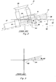
- Figures 3 and 5 are provided to facilitate visualization of angles 34, 36, 38 and 40 with combine 10 removed.
- angle 40 of lateral tilt of header 12 to reference 42 is the same as lateral tilt angle 36 of combine 10 because header 12 is not tilted relative to combine 10, i.e. angle 38 of lateral tilt relative to combine 10 is zero.
- angle 40 of lateral tilt of header 12 to reference 42 is the same as angle 34 of the laterally inclined surface because system 30 has provided a header tilt command for adjusting angle 38 of lateral tilt of header 12 relative to combine 10.
- Figure 6 depicts system 30 as used in conjunction with combine 10 equipped with dual tires.
- the at least one additional characteristic monitored by controller 32 includes those characteristics that can affect the downward and sideward forces and moments acting on combine 10, particularly at tires 14, 16.
- a grain tank 26, located high on combine 10 can create a greater moment of inertia about the center of gravity of combine 10 that urges combine 10 to tilt more "downhill", thus increasing the forces on tire 14, when full than that moment created when grain tank 26 is empty.
- These additional characteristics may include, as seen in Figure 7 , rate of change of angle 34 of laterally inclined surface 28, ground speed of combine 10, soil or surface characteristics, number of tires, engine load, weight of grain, amount of fuel, characteristics of tires 14, 16, including material, number of plies, type and spacing of tread, and the like.
- system 30 includes a knowledge base including characteristics with weighted values. For example, at greater angles of inclination, the weight of the grain may be weighted more heavily because of height of the grain tank. In addition, certain combinations of factors, when present may be weighted more heavily.
- Another embodiment of the invention includes monitoring a differentiation between at least two tires 14, 16 disposed on opposite sides of combine 10 for a threshold difference in loading conditions experienced by tires 14, 16 and/or a threshold difference between air pressure in tires 14, 16.
- the predetermined amount of difference allowed between lateral tilt angle 36 and angle 34 of laterally inclined surface 28 is based on information representative of a vertical height of header 12.
- the predetermined amount is larger, allowing a greater difference between the angles, when header 12 is positioned at a larger vertical height.
- the predetermined amount is smaller, allowing less difference between the angles, when header 12 is positioned at a lower vertical height.
- Still another embodiment of system 30 includes an operator override capability 44, wherein the operator can manually override the automatic adjustment of angle 38 of lateral tilt of the header and controller 30 is configured and operable to learn from the override.
- lateral inclination sensor 22 may be, for instance, an inclinometer of the type that is commonly used with a self-leveling grain cleaning system 24 within combine 10 or any other suitable device capable of providing information representative of lateral tilt angle 36 of combine 10.
Landscapes
- Life Sciences & Earth Sciences (AREA)
- Environmental Sciences (AREA)
- Lifting Devices For Agricultural Implements (AREA)
- Harvester Elements (AREA)
- Guiding Agricultural Machines (AREA)
Abstract
Description
- This invention relates generally to a system and method for controlling the angle of lateral tilt of a header of an agricultural plant cutting machine, such as, but not limited to, a combine, windrower or the like, when disposed on a laterally inclined surface and more particularly, to an automatic lateral tilt control system which precisely controls an angle of lateral tilt of the header relative to the machine based on a lateral tilt angle of the machine relative to a reference and at least one additional characteristic.
- Agricultural plant cutting and harvesting machines typically have a header which is desired or required to be positioned at one or more selectable cutting heights in relation to the surface, and at angles of sideward tilt in relation to the machine itself, as well as to a surface over which the machine is driven. Such capability is illustrated in
AU-B-548902 US-A-6,523,333 , is generally only useful when the header is positioned very close to, or on, the surface. Thus typical ground sensing capability, if present at all, is unavailable or inoperable when the machine is operating in the stubble mode. - When the machine is disposed on a laterally inclined surface, downward and sideward forces acting on it can result in tire deformation, ground compaction, and the like on the downhill side. It has been observed that these forces can cause the machine to tilt to a lateral tilt angle that is different, usually greater, than an angle of the laterally inclined surface. Unless tilted relative to the machine, the header is disposed at the same lateral tilt angle resulting in a downhill side of the header riding closer to the surface than an uphill side of the header.
- For shorter headers and/or very small differences between the machine tilt angle and the angle of inclination of the surface, the height difference at the ends of the header may not present a problem. However, for longer headers this angular difference causes a more pronounced height difference at the ends of the header such that the downhill side of the header may ride significantly closer to the surface than the uphill side. In some circumstances, this may lead to undesirably uneven cutting height and risks possible damage to the cutting apparatus due to impact with the ground. In this situation an operator typically provides an uphill tilt correction to compensate for the undesired sideward or transverse tilt angle of the header.
- It is known to use an inclinometer to provide a lateral tilt angle at which the machine is operating for use with a self-leveling grain cleaning system within the machine.
- It is desirable to automatically adjust the transverse tilt angle of the header such that it takes a position parallel to the ground surface, even in the stubble mode where conventional sensors arms float above the surface. Such adjustment should maintain desired cutting height, reduce the possibility of damage to the cutting apparatus of the header, and reduce operator workload.
- Thus, what is sought is an automatic lateral tilt control system and method for a header for a plant cutting machine which overcomes one or more of the shortcomings and limitations set forth above.
- According to one aspect of the invention there is provided automatic lateral tilt control system for a header of an agricultural plant cutting machine, comprising:
- at least one driver connected to the header and configured so as to be controllably operable by a header tilt command input for varying an angle of lateral tilt of the header relative to the plant cutting machine;
- a lateral inclination sensor configured and operable for providing information representative of a lateral tilt angle of the machine relative to a reference; and
- a controller programmed and operable for automatically monitoring the information representative of the lateral tilt angle of the machine,
- characterised in that the controller is programmed and operable for:
- automatically monitoring further information representative of at least one additional characteristic;
- deriving information representative of an angle of the laterally inclined surface to the reference from the information representative of the lateral tilt angle of the machine and the information representative of at least one additional characteristic, and
- when the machine is disposed on a laterally inclined surface and the machine is tilted such that the information representative of the lateral tilt angle differs by a predetermined amount from the derived information representative of the angle of the laterally inclined surface, responsively adjusting the angle of lateral tilt of the header relative to the machine, so an angle of lateral tilt of the header relative to the reference is at least substantially equal to the angle of the laterally inclined surface to the reference
- According to a second aspect of the invention there is provided a method for automatically controlling the lateral tilt of a header of an agricultural plant cutting machine, comprising:
- providing at least one driver connected to the header and configured so as to be controllably operable for varying an angle of lateral tilt of the header relative to the plant cutting machine;
- providing a lateral inclination sensor configured and operable for providing information representative of a lateral tilt angle of the machine relative to a reference; and
- automatically monitoring the information representative of the lateral tilt angle of the machine,
- characterised in that said method further comprises:
- automatically monitoring information representative of at least one additional characteristic;
- deriving further information representative of an angle of the laterally inclined surface to the reference from the information representative of the lateral tilt angle of the machine and the information representative of at least one additional characteristic; and
- when the machine is disposed on a laterally inclined surface, and the machine is tilted such that the information representative of the lateral tilt angle differs by a predetermined amount from the derived information representative of the angle of the laterally inclined surface, responsively adjusting the angle of lateral tilt of the header relative to the machine so an angle of lateral tilt of the header relative to the reference is at least substantially equal to the angle of the laterally inclined surface relative to the reference.
- Hence, the invention uses the lateral tilt angle of the machine provided by the inclinometer and an additional characteristic to model or predict the lateral tilt angle of the inclined surface so as to provide automatic compensation of the header tilt angle to maintain desired cutting height, thereby reducing the possibility of damage to the cutting apparatus of the header, and reducing operator workload.
- In a preferred embodiment of the invention, the system includes at least one driver in connection with the header configured so as to be controllably operable by a header tilt command input for varying an angle of lateral tilt of the header relative to the machine, and a lateral inclination sensor, such as an inclinometer, configured and operable for providing information representative of the lateral tilt angle of the machine relative to a reference, which can be, for example, horizontal. The system includes a controller programmed and operable for automatically monitoring the information representative of the lateral tilt angle of the machine, and at least one additional characteristic, and uses this information for deriving information representative of the angle of the laterally inclined surface relative to the reference. When the machine is disposed on the laterally inclined surface, and the machine is tilted such that the information representative of the lateral tilt angle of the machine differs by a predetermined amount from information representative of the angle of the laterally inclined surface, the system will responsively adjust the angle of lateral tilt of the header relative to the machine, so an angle of lateral tilt of the header relative to the reference is at least substantially equal to the angle of the laterally inclined surface, while the machine remains at the different angle to the surface.
- The additional characteristic or characteristics monitored by the controller preferably include those characteristics that affect the downward and sideward forces and moments acting on the machine. These additional characteristics may include, but are not limited to, rate of change of the angle of the laterally inclined surface, ground speed of the machine, soil or surface characteristics, number of tires, engine load, weight of grain, amount of fuel, characteristics of tires including material, number of plies, type and spacing of tread, and the like.
- Advantageously, the system can include a knowledge base including characteristics with weighted values.
- Another embodiment of the invention includes monitoring a differentiation between at least two tires disposed on opposite sides of the machine for a threshold difference in loading conditions experienced by the tires and/or a threshold difference between air pressures in the tires.
- According to yet another preferred embodiment of the invention, the predetermined amount of difference allowed between the lateral tilt angle of the machine and the angle of the laterally inclined surface is based on a vertical height of the header above the surface. The predetermined amount is larger, allowing a greater difference between the angles, when the header is positioned at a larger vertical cutting height. Conversely the predetermined amount is smaller, allowing less difference between the angles, when the header is positioned at a lower vertical cutting height.
- Still another preferred embodiment of the system includes an operator override capability, wherein the operator can manually override the automatic adjustment of the angle of lateral tilt of the header relative to the machine and the controller is configured and operable to learn from the override.
- The lateral inclination sensor may be, for instance, an inclinometer of the type that is commonly used with a self-leveling grain cleaning system or any other suitable device capable of providing information representative of the lateral tilt angle of the machine.
-
-
Figure 1 is a simplified front view of a representative agricultural plant cutting machine including a header for use with the present invention; -
Figure 2 is a simplified front view of the plant cutting machine ofFigure 1 disposed on an inclined surface depicting an observed situation noted in the prior art; -
Figure 3 is a simplified representation ofFigure 2 with the machine removed to facilitate visualization of angles shown inFigure 2 ; -
Figure 4 is a simplified front view of the plant cutting machine ofFigure 1 disposed on an inclined surface according to the invention; -
Figure 5 is a simplified representation ofFigure 4 with the machine removed to facilitate visualization of angles shown inFigure 4 ; -
Figure 6 is simplified front view of a plant cutting machine having dual tires disposed on an inclined surface according to the invention; and -
Figure 7 is a simplified representation of elements and signals for use in the method and control system of the invention. - Referring now to the drawings,
Figure 1 depicts a simplified front view of a representative self-propelled agricultural plant cutting machine, such as acombine 10, including aplant cutting header 12 mounted thereon.Combine 10 is intended to be representative of a wide variety of agricultural plant cutting and harvesting machines and other workmachines having header 12 which is desired or required to be positioned at one or more selectable cutting heights in relation to the surface, and angles of sideward tilt in relation to the machine itself, as well as to a surface over which the machine is driven. Whenheader 12 is positioned at a cutting height above the surface, such that the stalks of crops are left at a higher level,combine 10 is sometimes referred to as operating in a "stubble mode". Since conventional ground sensing capability is generally only useful whenheader 12 is positioned very close to, or on, the surface, typical ground sensing capability, if present at all, is unavailable whencombine 10 is operating in the stubble mode,i.e. header 12 is positioned at a height above the surface. - As depicted in
Figures 2-5 , whencombine 10 is disposed on a laterallyinclined surface 28, downward and sideward forces acting oncombine 10 can result in greater tire deformation, ground compaction, and the like on the downhill side of the machine, as represented by adownhill tire 14 shown deformed as compared to anuphill tire 16. As a result,combine 10 is at alateral tilt angle 36 that is greater than anangle 34 of laterallyinclined surface 28, both angles measured from ahorizontal reference 42, as shown. Accordingly,header 12, unless tilted relative to combine 10, is disposed at the samelateral tilt angle 36 as combine 10 relative toreference 42. It has been observed that this situation, as illustrated by the prior art representation ofFigure 2 , often results in a downhill side 11 ofheader 12 riding closer to surface 28 than anuphill side 13 ofheader 12. In some circumstances, this may lead to undesirably uneven cutting height and risks possible damage to the cutting apparatus due to impact with the ground. - With reference to
Figures 1 and4 ,header 12 is typically tilted relative to combine 10 by at least one driver, such as ahydraulic valve 18 in fluid communication with anactuator 20 for example, which is connected toheader 12 and configured so as to be controllably operable by a header tilt command input for varying anangle 38 of lateral tilt ofheader 12 relative to combine 10. Alateral inclination sensor 22 is configured and operable for providing information representative oflateral tilt angle 36 ofcombine 10 relative to a reference, in this case,horizontal reference 42. - With reference to
Figures 4 and7 , according to the invention, an automatic lateraltilt control system 30 includes acontroller 32 programmed and operable for automatically monitoring the information representative oflateral tilt angle 36 ofcombine 10 and at least one additional characteristic for predicting or deriving information representative ofangle 34 of laterally inclined surface relative to reference 42.System 30 can now compare its derivedangle 34 of laterally inclinedsurface 28 with its sensedlateral tilt angle 36 ofcombine 10. When combine 10 is disposed on laterallyinclined surface 28 and combine 10 is tilted such that information representative oflateral tilt angle 36 ofcombine 10 differs by a predetermined amount from information representative ofangle 34 of laterally inclinedsurface 28,system 30 responsively adjustsangle 38 of lateral tilt ofheader 12 relative to combine 10, so an angle 40 of lateral tilt ofheader 12 relative to reference 42 is at least substantially equal toangle 34 of laterally inclinedsurface 28. -
Figures 3 and5 are provided to facilitate visualization ofangles combine 10 removed. For example, in the prior art representation ofFigure 3 , angle 40 of lateral tilt ofheader 12 to reference 42 is the same aslateral tilt angle 36 ofcombine 10 becauseheader 12 is not tilted relative to combine 10, i.e.angle 38 of lateral tilt relative to combine 10 is zero. It is important to note that inFigure 5 , angle 40 of lateral tilt ofheader 12 to reference 42 is the same asangle 34 of the laterally inclined surface becausesystem 30 has provided a header tilt command for adjustingangle 38 of lateral tilt ofheader 12 relative to combine 10. -
Figure 6 depictssystem 30 as used in conjunction withcombine 10 equipped with dual tires. - The at least one additional characteristic monitored by
controller 32 includes those characteristics that can affect the downward and sideward forces and moments acting oncombine 10, particularly attires grain tank 26, located high oncombine 10, can create a greater moment of inertia about the center of gravity ofcombine 10 that urgescombine 10 to tilt more "downhill", thus increasing the forces ontire 14, when full than that moment created whengrain tank 26 is empty. These additional characteristics may include, as seen inFigure 7 , rate of change ofangle 34 of laterally inclinedsurface 28, ground speed ofcombine 10, soil or surface characteristics, number of tires, engine load, weight of grain, amount of fuel, characteristics oftires - According to another aspect of the invention,
system 30 includes a knowledge base including characteristics with weighted values. For example, at greater angles of inclination, the weight of the grain may be weighted more heavily because of height of the grain tank. In addition, certain combinations of factors, when present may be weighted more heavily. - Another embodiment of the invention includes monitoring a differentiation between at least two
tires combine 10 for a threshold difference in loading conditions experienced bytires tires - According to yet another embodiment of the invention, the predetermined amount of difference allowed between
lateral tilt angle 36 andangle 34 of laterally inclinedsurface 28 is based on information representative of a vertical height ofheader 12. The predetermined amount is larger, allowing a greater difference between the angles, whenheader 12 is positioned at a larger vertical height. Conversely the predetermined amount is smaller, allowing less difference between the angles, whenheader 12 is positioned at a lower vertical height. Thus, at lower vertical heights, whereheader 12 risks impacting with the ground whencombine 10 is at alateral tilt angle 36 that is greater thanangle 34 of laterally inclined surface,system 30 provides tighter tolerances. - Still another embodiment of
system 30 includes anoperator override capability 44, wherein the operator can manually override the automatic adjustment ofangle 38 of lateral tilt of the header andcontroller 30 is configured and operable to learn from the override. - According to another aspect of the invention,
lateral inclination sensor 22 may be, for instance, an inclinometer of the type that is commonly used with a self-levelinggrain cleaning system 24 withincombine 10 or any other suitable device capable of providing information representative oflateral tilt angle 36 ofcombine 10. - In light of all the foregoing, it should thus be apparent to those skilled in the art that, within the scope of the invention as defined by the claims, many changes are possible and contemplated, including in the details, materials, and arrangements of parts which have been described and illustrated to explain the invention. Thus, while the foregoing description and discussion addresses certain preferred embodiments or elements of the invention, it should further be understood that concepts of the invention, as based upon the foregoing description and discussion, may be readily incorporated into or employed in other embodiments and constructions without departing from said scope of the invention.
Claims (19)
- An automatic lateral tilt control system (30) for a header (12) of an agricultural plant cutting machine (10), comprising:at least one driver (18) connected to the header and configured so as to be controllably operable by a header tilt command input for varying an angle (38) of lateral tilt of the header relative to the plant cutting machine;a lateral inclination sensor (22) configured and operable for providing information representative of a lateral tilt angle (36) of the machine (10) relative to a reference (42); anda controller (32) programmed and operable for automatically monitoring the information representative of the lateral tilt angle (36) of the machine,characterised in that the controller is programmed and operable for:automatically monitoring further information representative of at least one additional characteristic;deriving information representative of an angle (34) of the laterally inclined surface (28) to the reference (42) from the information representative of the lateral tilt angle (36) of the machine (10) and the information representative of at least one additional characteristic, andwhen the machine is disposed on a laterally inclined surface (28) and the machine is tilted such that the information representative of the lateral tilt angle (36) differs by a predetermined amount from the derived information representative of the angle (34) of the laterally inclined surface (28), responsively adjusting the angle (38) of lateral tilt of the header (12) relative to the machine (10), so an angle (40) of lateral tilt of the header (12) relative to the reference (42) is at least substantially equal to the angle (34) of the laterally inclined surface (28) to the reference (42).
- A control system according to claim 1, characterised in that the at least one additional characteristic includes a rate of change of the lateral inclination (36) of the machine (10) relative to the predetermined reference (42).
- A control system according to claim 1or 2, characterised in that the at least one additional characteristic includes a ground speed of the machine (10).
- A control system according to any of the preceding claims, characterised in that the at least one additional characteristic includes a differentiation between at least two tires (14, 16) disposed on opposite sides of the machine (10).
- A control system according to claim 4, characterised in that the differentiation between the tires (14, 16) is a load differentiation.
- A control system according to claim 4 or 5, characterised in that the differentiation between the tires (14, 16) is an air pressure differentiation.
- A control system according to any of the preceding claims, characterised in that the at least one additional characteristic is information representative of a vertical height of the header (12) relative to the lateral surface (28), and the predetermined amount is larger when the vertical height is larger and the predetermined amount is smaller when the vertical height is smaller.
- A control system according to any of the preceding claims, characterised in that it includes a knowledge base including characteristics having weighted values.
- A control system according to any of the preceding claims, characterised in that it includes an operator override capability (44) wherein the operator can manually override the automatic adjustment of the angle of lateral tilt of the header (12) and the controller (32) is configured and operable to learn from the override.
- A control system according to any of the preceding claims, characterised in that the lateral inclination sensor (22) is an inclinometer.
- A method for automatically controlling the lateral tilt of a header (12) of an agricultural plant cutting machine (10), comprising:providing at least one driver (18) connected to the header (12) and configured so as to be controllably operable for varying an angle (38) of lateral tilt of the header (12) relative to the plant cutting machine (10);providing a lateral inclination sensor (22) configured and operable for providing information representative of a lateral tilt angle (36) of the machine (10) relative to a reference (42); andautomatically monitoring the information representative of the lateral tilt angle (36) of the machine,characterised in that said method further comprises:automatically monitoring information representative of at least one additional characteristic;deriving further information representative of an angle (34) of the laterally inclined surface (28) to the reference (42) from the information representative of the lateral tilt angle (36) of the machine (10) and the information representative of at least one additional characteristic; andwhen the machine (10) is disposed on a laterally inclined surface (28), and the machine (10) is tilted such that the information representative of the lateral tilt angle (36) differs by a predetermined amount from the derived information representative of the angle (34) of the laterally inclined surface (28), responsively adjusting the angle (38) of lateral tilt of the header (12) relative to the machine (12) so an angle (40) of lateral tilt of the header (12) relative to the reference (42) is at least substantially equal to the angle (34) of the laterally inclined surface (28) relative to the reference (42).
- A method according to claim 11, characterised in that the at least one additional characteristic includes a rate of change of the lateral inclination (36) of the machine (10) relative to the predetermined reference (42).
- A method according to claim 11 or 12, characterised in that the at least one additional characteristic includes a ground speed of the machine (10).
- A method according to any of the claims 11 to 13, characterised in that the at least one additional characteristic includes a differentiation between at least two tires (14, 16) disposed on opposite sides of the machine (10).
- A method according to claim 14, characterised in that the differentiation between the tires (14, 16) is a load differentiation.
- A method according to claim 14 or 15, characterised in that the differentiation between the tires (14, 16) is an air pressure differentiation.
- A method according to any of the claims 11 to 16, characterised in that the at least one additional characteristic is a vertical height of the header (12) relative to the reference (42) and the predetermined amount is larger when the header (12) is positioned at a higher vertical height and the predetermined amount is smaller when the header is positioned at a lower vertical height.
- A method according to any of the claims 11 to 17, characterised in that the system includes a knowledge base including characteristics having weighted values.
- A method according to any of the claims 11 to 18, characterised in that it further comprises:allowing an operator to manually override the automatic adjustment of the angle (38) of lateral tilt of the header (12); andoperating the controller (32) to learn from the override.
Applications Claiming Priority (1)
| Application Number | Priority Date | Filing Date | Title |
|---|---|---|---|
| US12/392,669 US7870709B2 (en) | 2009-02-25 | 2009-02-25 | Automatic lateral tilt control of a header in stubble height mode using machine level sensor |
Publications (2)
| Publication Number | Publication Date |
|---|---|
| EP2225930A1 true EP2225930A1 (en) | 2010-09-08 |
| EP2225930B1 EP2225930B1 (en) | 2012-05-09 |
Family
ID=42335244
Family Applications (1)
| Application Number | Title | Priority Date | Filing Date |
|---|---|---|---|
| EP10154697A Active EP2225930B1 (en) | 2009-02-25 | 2010-02-25 | Automatic lateral tilt control of a header in stubble height mode using a machine level sensor |
Country Status (3)
| Country | Link |
|---|---|
| US (1) | US7870709B2 (en) |
| EP (1) | EP2225930B1 (en) |
| AT (1) | ATE556582T1 (en) |
Cited By (2)
| Publication number | Priority date | Publication date | Assignee | Title |
|---|---|---|---|---|
| EP2444304A1 (en) * | 2010-10-25 | 2012-04-25 | Bordini Engineering Srl | System and method for preventing overturning of land vehicles |
| CN111165170A (en) * | 2020-03-01 | 2020-05-19 | 范巍挺 | A small hand-held sugarcane fine cutting machine and its control method |
Families Citing this family (24)
| Publication number | Priority date | Publication date | Assignee | Title |
|---|---|---|---|---|
| US8720170B2 (en) * | 2011-10-18 | 2014-05-13 | Deere & Company | Header height control with tire flex compensation |
| DE102012223770A1 (en) * | 2012-12-19 | 2014-06-26 | Deere & Company | Inclined conveyor assembly with flexible bottom |
| DE102012223769A1 (en) * | 2012-12-19 | 2014-06-26 | Deere & Company | Inclined conveyor assembly with improved swing axle |
| US9265199B2 (en) * | 2013-11-21 | 2016-02-23 | Deere & Company | Side hill compensation for a harvesting head |
| US9693502B2 (en) * | 2014-10-24 | 2017-07-04 | Agco Corporation | Active header control |
| US9844184B2 (en) * | 2015-03-17 | 2017-12-19 | Agco Corporation | Header position sensing system for an agricultural harvester |
| US10182525B2 (en) | 2017-05-17 | 2019-01-22 | Cnh Industrial America Llc | Feeder and header positioning method |
| US10356972B2 (en) | 2017-08-01 | 2019-07-23 | Cnh Industrial America Llc | System and method for reducing variations in the penetration depths of ground-engaging tools of an agricultural implement based on monitored tire pressures |
| US10472798B2 (en) * | 2017-09-20 | 2019-11-12 | Deere & Company | Work implement control based on tire pressure in a construction vehicle |
| EP3729934A1 (en) | 2019-04-25 | 2020-10-28 | CNH Industrial Sweden AB | Plough |
| EP3741200B1 (en) * | 2019-05-20 | 2024-01-10 | CNH Industrial Belgium N.V. | Control system and method for agricultural harvester |
| US11659785B2 (en) * | 2019-10-23 | 2023-05-30 | Cnh Industrial America Llc | Method and system for controlling the height of an agricultural implement relative to the ground |
| US11793109B2 (en) | 2020-02-13 | 2023-10-24 | Techtronic Cordless Gp | Lawnmowers with safety features and methods associated therewith |
| US11730076B2 (en) | 2020-03-26 | 2023-08-22 | Cnh Industrial America Llc | Control system for an agricultural implement |
| US11558993B2 (en) | 2020-03-26 | 2023-01-24 | Cnh Industrial America Llc | Soil monitoring system for an agricultural tillage implement |
| US11638393B2 (en) | 2020-03-26 | 2023-05-02 | Cnh Industrial America Llc | Ground engaging tool monitoring system |
| US11602092B2 (en) | 2020-03-26 | 2023-03-14 | Cnh Industrial America Llc | Frame control system for an agricultural implement |
| US11617294B2 (en) | 2020-03-26 | 2023-04-04 | Cnh Industrial America Llc | Orientation control system for an agricultural implement |
| US12022756B2 (en) | 2020-03-26 | 2024-07-02 | Cnh Industrial America Llc | Orientation control system for an agricultural implement |
| US20220167554A1 (en) * | 2020-11-30 | 2022-06-02 | Deere & Company | Mower deck hillside adjustment system |
| CN112913366A (en) * | 2021-01-25 | 2021-06-08 | 陈德富 | Agricultural machine capable of being dynamically leveled and control method thereof |
| SE2150494A1 (en) * | 2021-04-21 | 2022-05-24 | Husqvarna Ab | Yard maintenance vehicle with advanced tilt monitoring capabilities |
| CN113519273A (en) * | 2021-07-12 | 2021-10-22 | 中国铁建重工集团股份有限公司 | Header mechanism, profiling control method and profiling control system |
| US20240000014A1 (en) * | 2022-06-30 | 2024-01-04 | Cnh Industrial America Llc | Systems and methods for automatically identifying sensors associated with agricultural equipment |
Citations (7)
| Publication number | Priority date | Publication date | Assignee | Title |
|---|---|---|---|---|
| US4527381A (en) * | 1983-10-13 | 1985-07-09 | Sperry Corporation | Lateral flotation mechanism for combine harvesters |
| AU548902B2 (en) | 1981-04-07 | 1986-01-09 | New Holland Australia Limited | Harvester head flotation |
| US4612757A (en) * | 1985-04-12 | 1986-09-23 | Sperry Corporation | Combine header attitude control mechanism |
| US5381645A (en) * | 1992-05-06 | 1995-01-17 | Schumacher; Gustav | Control for a structural assembly self-aligningly supported on an agricultural machine |
| US5535577A (en) * | 1993-02-01 | 1996-07-16 | Control Concepts, Inc. | Agricultural harvester with closed loop ground tracking control |
| US20020069628A1 (en) * | 2000-12-06 | 2002-06-13 | Metzger Leo A. | Sensor arm for combine header |
| US6615569B1 (en) | 1999-10-05 | 2003-09-09 | Case Corporation | Control system to automatically center an agricultural harvester header |
Family Cites Families (26)
| Publication number | Priority date | Publication date | Assignee | Title |
|---|---|---|---|---|
| DE19705583A1 (en) | 1997-02-14 | 1998-08-20 | Deere & Co | Harvester |
| US3269685A (en) | 1965-05-28 | 1966-08-30 | Frank Hamachek Machine Company | Leveling control for electrically operating hydraulic leveling means |
| US4548214A (en) | 1984-10-11 | 1985-10-22 | Sperry Corporation | Fore-and-aft leveling mechanism for combine cleaning apparatus |
| US4557276A (en) | 1984-10-11 | 1985-12-10 | Sperry Corporation | Four way leveling mechanism for combine cleaning apparatus |
| US4535788A (en) | 1984-10-11 | 1985-08-20 | Sperry Corporation | Lateral leveling mechanism for combine cleaning apparatus |
| EP0243540B1 (en) * | 1986-05-02 | 1990-08-16 | Ford New Holland N.V. | Header flotation system for an agricultural machine |
| DE3807610A1 (en) | 1988-03-09 | 1989-09-21 | Claas Ohg | DEVICE AND METHOD FOR CONTROLLING THE POSITION OF A MOWING MACHINE |
| DE3822689A1 (en) | 1988-07-05 | 1990-01-11 | Deere & Co | CONVEYOR DEVICE |
| US4944141A (en) | 1988-12-09 | 1990-07-31 | Fmc Corporation | Height control system |
| US5918448A (en) * | 1997-02-06 | 1999-07-06 | Agco Corporation | Combine header lateral tilt assembly |
| DE19726917A1 (en) | 1997-06-25 | 1999-01-07 | Claas Selbstfahr Erntemasch | Device on agricultural machinery for contactless scanning of contours extending over the ground |
| US5995895A (en) * | 1997-07-15 | 1999-11-30 | Case Corporation | Control of vehicular systems in response to anticipated conditions predicted using predetermined geo-referenced maps |
| DE10018211A1 (en) | 2000-04-12 | 2001-11-22 | Claas Selbstfahr Erntemasch | Agricultural harvester |
| US6615570B2 (en) | 2001-06-28 | 2003-09-09 | Deere & Company | Header position control with forward contour prediction |
| US6592453B2 (en) * | 2001-09-27 | 2003-07-15 | Deere & Company | Harvester feedrate control with tilt compensation |
| DE10227484A1 (en) * | 2002-06-19 | 2004-02-26 | Claas Selbstfahrende Erntemaschinen Gmbh | Device and method for controlling the position of a harvesting device of agricultural harvesting machines |
| US6843719B1 (en) * | 2003-10-30 | 2005-01-18 | David Sacquitne | Floating combine sieve assembly |
| US6983583B2 (en) * | 2003-11-21 | 2006-01-10 | Ariens Company | Lawnmower tilt sensor apparatus and method |
| US7580783B2 (en) * | 2004-12-29 | 2009-08-25 | Cnh America Llc | Correction in position with hitch position sensor |
| US7748203B2 (en) * | 2005-02-16 | 2010-07-06 | The Factory Company International, Inc. | Tilting implements and constructions for hillside implements such as hillside combine harvesters |
| US7222474B2 (en) * | 2005-04-29 | 2007-05-29 | Cnh America Llc | Ground sensing apparatus for a header of an agricultural harvesting machine |
| US7191582B2 (en) * | 2005-05-10 | 2007-03-20 | Deere & Company | Header terrain following system |
| US7306513B2 (en) * | 2005-11-30 | 2007-12-11 | Deere & Company | Leveling by over-compensation |
| US7603837B2 (en) * | 2006-01-13 | 2009-10-20 | Cnh America Llc | Header height control system and apparatus |
| US8180532B2 (en) * | 2006-05-26 | 2012-05-15 | Deere & Company | Vector controlled leveling system for a forestry machine |
| US9615501B2 (en) * | 2007-01-18 | 2017-04-11 | Deere & Company | Controlling the position of an agricultural implement coupled to an agricultural vehicle based upon three-dimensional topography data |
-
2009
- 2009-02-25 US US12/392,669 patent/US7870709B2/en active Active
-
2010
- 2010-02-25 EP EP10154697A patent/EP2225930B1/en active Active
- 2010-02-25 AT AT10154697T patent/ATE556582T1/en active
Patent Citations (8)
| Publication number | Priority date | Publication date | Assignee | Title |
|---|---|---|---|---|
| AU548902B2 (en) | 1981-04-07 | 1986-01-09 | New Holland Australia Limited | Harvester head flotation |
| US4527381A (en) * | 1983-10-13 | 1985-07-09 | Sperry Corporation | Lateral flotation mechanism for combine harvesters |
| US4612757A (en) * | 1985-04-12 | 1986-09-23 | Sperry Corporation | Combine header attitude control mechanism |
| US5381645A (en) * | 1992-05-06 | 1995-01-17 | Schumacher; Gustav | Control for a structural assembly self-aligningly supported on an agricultural machine |
| US5535577A (en) * | 1993-02-01 | 1996-07-16 | Control Concepts, Inc. | Agricultural harvester with closed loop ground tracking control |
| US6615569B1 (en) | 1999-10-05 | 2003-09-09 | Case Corporation | Control system to automatically center an agricultural harvester header |
| US20020069628A1 (en) * | 2000-12-06 | 2002-06-13 | Metzger Leo A. | Sensor arm for combine header |
| US6523333B2 (en) | 2000-12-06 | 2003-02-25 | Leo A. Metzger | Sensor arm for combine header |
Cited By (4)
| Publication number | Priority date | Publication date | Assignee | Title |
|---|---|---|---|---|
| EP2444304A1 (en) * | 2010-10-25 | 2012-04-25 | Bordini Engineering Srl | System and method for preventing overturning of land vehicles |
| ITMO20100296A1 (en) * | 2010-10-25 | 2012-04-26 | Bordini Engineering Srl | SYSTEM AND METHOD TO PREVENT A TILTING OF LAND VEHICLES |
| CN111165170A (en) * | 2020-03-01 | 2020-05-19 | 范巍挺 | A small hand-held sugarcane fine cutting machine and its control method |
| CN111165170B (en) * | 2020-03-01 | 2022-02-08 | 范巍挺 | Small-sized walking sugarcane precision cutting machine and control method thereof |
Also Published As
| Publication number | Publication date |
|---|---|
| US20100212276A1 (en) | 2010-08-26 |
| EP2225930B1 (en) | 2012-05-09 |
| US7870709B2 (en) | 2011-01-18 |
| ATE556582T1 (en) | 2012-05-15 |
Similar Documents
| Publication | Publication Date | Title |
|---|---|---|
| EP2225930B1 (en) | Automatic lateral tilt control of a header in stubble height mode using a machine level sensor | |
| US7707811B1 (en) | Header flotation and lift system with dual mode operation for a plant cutting machine | |
| US9345191B2 (en) | Self-propelled harvesting machine having a vertically controlled header | |
| US7520115B2 (en) | Header float arm load compensation | |
| EP2832206B1 (en) | Header lateral tilt control with automatic operation in free float and controlled tilt modes | |
| US7552577B2 (en) | Header flotation calibration system | |
| US8560182B2 (en) | Implement height control adjustment on agricultural vehicles | |
| EP3695703B1 (en) | Windrower with ground contour sensing system and ground contour sensing method | |
| EP3735123B1 (en) | Draper header for harvester | |
| EP3509412B1 (en) | Header height control system with multiple height sensors | |
| AU779747B2 (en) | Harvester row unit height control with electrohydraulic proportional valve structure | |
| US20090069988A1 (en) | Automatic calibration for a header flotation system | |
| EP3122169B1 (en) | Controlling cutting height and angle of a combine header | |
| US8109069B2 (en) | Proportional counterbalance system for mower cutting units | |
| US11375654B2 (en) | Method and apparatus for adjusting a harvesting header float system based on machine pitch or terrain and system thereof | |
| CN101261522A (en) | Lifting control device for agricultural machine | |
| AU2019202982A1 (en) | Crop machine with an electronically controlled hydraulic cylinder flotation system | |
| JP6260439B2 (en) | Seedling transplanter | |
| AU2019202981A1 (en) | Crop machine with an electronically controlled hydraulic cylinder flotation system | |
| CA2606003C (en) | Header float arm load compensation | |
| JP2688127B2 (en) | Lifting control device for work equipment | |
| JP2000139137A (en) | Seedling transplanter | |
| JP3372465B2 (en) | Lifting and lowering control device for farm equipment | |
| WO2025166464A1 (en) | Method for controlling cut height | |
| JPH06261602A (en) | Lifting control device for work equipment |
Legal Events
| Date | Code | Title | Description |
|---|---|---|---|
| PUAI | Public reference made under article 153(3) epc to a published international application that has entered the european phase |
Free format text: ORIGINAL CODE: 0009012 |
|
| AK | Designated contracting states |
Kind code of ref document: A1 Designated state(s): AT BE BG CH CY CZ DE DK EE ES FI FR GB GR HR HU IE IS IT LI LT LU LV MC MK MT NL NO PL PT RO SE SI SK SM TR |
|
| AX | Request for extension of the european patent |
Extension state: AL BA RS |
|
| 17P | Request for examination filed |
Effective date: 20110308 |
|
| GRAP | Despatch of communication of intention to grant a patent |
Free format text: ORIGINAL CODE: EPIDOSNIGR1 |
|
| GRAS | Grant fee paid |
Free format text: ORIGINAL CODE: EPIDOSNIGR3 |
|
| GRAA | (expected) grant |
Free format text: ORIGINAL CODE: 0009210 |
|
| AK | Designated contracting states |
Kind code of ref document: B1 Designated state(s): AT BE BG CH CY CZ DE DK EE ES FI FR GB GR HR HU IE IS IT LI LT LU LV MC MK MT NL NO PL PT RO SE SI SK SM TR |
|
| REG | Reference to a national code |
Ref country code: GB Ref legal event code: FG4D |
|
| REG | Reference to a national code |
Ref country code: AT Ref legal event code: REF Ref document number: 556582 Country of ref document: AT Kind code of ref document: T Effective date: 20120515 Ref country code: CH Ref legal event code: EP |
|
| REG | Reference to a national code |
Ref country code: IE Ref legal event code: FG4D |
|
| REG | Reference to a national code |
Ref country code: DE Ref legal event code: R096 Ref document number: 602010001337 Country of ref document: DE Effective date: 20120705 |
|
| REG | Reference to a national code |
Ref country code: NL Ref legal event code: VDEP Effective date: 20120509 |
|
| REG | Reference to a national code |
Ref country code: LT Ref legal event code: MG4D Effective date: 20120509 |
|
| PG25 | Lapsed in a contracting state [announced via postgrant information from national office to epo] |
Ref country code: PL Free format text: LAPSE BECAUSE OF FAILURE TO SUBMIT A TRANSLATION OF THE DESCRIPTION OR TO PAY THE FEE WITHIN THE PRESCRIBED TIME-LIMIT Effective date: 20120509 Ref country code: CY Free format text: LAPSE BECAUSE OF FAILURE TO SUBMIT A TRANSLATION OF THE DESCRIPTION OR TO PAY THE FEE WITHIN THE PRESCRIBED TIME-LIMIT Effective date: 20120509 Ref country code: LT Free format text: LAPSE BECAUSE OF FAILURE TO SUBMIT A TRANSLATION OF THE DESCRIPTION OR TO PAY THE FEE WITHIN THE PRESCRIBED TIME-LIMIT Effective date: 20120509 Ref country code: IS Free format text: LAPSE BECAUSE OF FAILURE TO SUBMIT A TRANSLATION OF THE DESCRIPTION OR TO PAY THE FEE WITHIN THE PRESCRIBED TIME-LIMIT Effective date: 20120909 Ref country code: SE Free format text: LAPSE BECAUSE OF FAILURE TO SUBMIT A TRANSLATION OF THE DESCRIPTION OR TO PAY THE FEE WITHIN THE PRESCRIBED TIME-LIMIT Effective date: 20120509 Ref country code: NO Free format text: LAPSE BECAUSE OF FAILURE TO SUBMIT A TRANSLATION OF THE DESCRIPTION OR TO PAY THE FEE WITHIN THE PRESCRIBED TIME-LIMIT Effective date: 20120809 Ref country code: FI Free format text: LAPSE BECAUSE OF FAILURE TO SUBMIT A TRANSLATION OF THE DESCRIPTION OR TO PAY THE FEE WITHIN THE PRESCRIBED TIME-LIMIT Effective date: 20120509 |
|
| REG | Reference to a national code |
Ref country code: AT Ref legal event code: MK05 Ref document number: 556582 Country of ref document: AT Kind code of ref document: T Effective date: 20120509 |
|
| PG25 | Lapsed in a contracting state [announced via postgrant information from national office to epo] |
Ref country code: LV Free format text: LAPSE BECAUSE OF FAILURE TO SUBMIT A TRANSLATION OF THE DESCRIPTION OR TO PAY THE FEE WITHIN THE PRESCRIBED TIME-LIMIT Effective date: 20120509 Ref country code: GR Free format text: LAPSE BECAUSE OF FAILURE TO SUBMIT A TRANSLATION OF THE DESCRIPTION OR TO PAY THE FEE WITHIN THE PRESCRIBED TIME-LIMIT Effective date: 20120810 Ref country code: PT Free format text: LAPSE BECAUSE OF FAILURE TO SUBMIT A TRANSLATION OF THE DESCRIPTION OR TO PAY THE FEE WITHIN THE PRESCRIBED TIME-LIMIT Effective date: 20120910 Ref country code: HR Free format text: LAPSE BECAUSE OF FAILURE TO SUBMIT A TRANSLATION OF THE DESCRIPTION OR TO PAY THE FEE WITHIN THE PRESCRIBED TIME-LIMIT Effective date: 20120509 Ref country code: SI Free format text: LAPSE BECAUSE OF FAILURE TO SUBMIT A TRANSLATION OF THE DESCRIPTION OR TO PAY THE FEE WITHIN THE PRESCRIBED TIME-LIMIT Effective date: 20120509 |
|
| PG25 | Lapsed in a contracting state [announced via postgrant information from national office to epo] |
Ref country code: BE Free format text: LAPSE BECAUSE OF FAILURE TO SUBMIT A TRANSLATION OF THE DESCRIPTION OR TO PAY THE FEE WITHIN THE PRESCRIBED TIME-LIMIT Effective date: 20120509 |
|
| PG25 | Lapsed in a contracting state [announced via postgrant information from national office to epo] |
Ref country code: NL Free format text: LAPSE BECAUSE OF FAILURE TO SUBMIT A TRANSLATION OF THE DESCRIPTION OR TO PAY THE FEE WITHIN THE PRESCRIBED TIME-LIMIT Effective date: 20120509 Ref country code: EE Free format text: LAPSE BECAUSE OF FAILURE TO SUBMIT A TRANSLATION OF THE DESCRIPTION OR TO PAY THE FEE WITHIN THE PRESCRIBED TIME-LIMIT Effective date: 20120509 Ref country code: SK Free format text: LAPSE BECAUSE OF FAILURE TO SUBMIT A TRANSLATION OF THE DESCRIPTION OR TO PAY THE FEE WITHIN THE PRESCRIBED TIME-LIMIT Effective date: 20120509 Ref country code: DK Free format text: LAPSE BECAUSE OF FAILURE TO SUBMIT A TRANSLATION OF THE DESCRIPTION OR TO PAY THE FEE WITHIN THE PRESCRIBED TIME-LIMIT Effective date: 20120509 Ref country code: CZ Free format text: LAPSE BECAUSE OF FAILURE TO SUBMIT A TRANSLATION OF THE DESCRIPTION OR TO PAY THE FEE WITHIN THE PRESCRIBED TIME-LIMIT Effective date: 20120509 Ref country code: RO Free format text: LAPSE BECAUSE OF FAILURE TO SUBMIT A TRANSLATION OF THE DESCRIPTION OR TO PAY THE FEE WITHIN THE PRESCRIBED TIME-LIMIT Effective date: 20120509 Ref country code: AT Free format text: LAPSE BECAUSE OF FAILURE TO SUBMIT A TRANSLATION OF THE DESCRIPTION OR TO PAY THE FEE WITHIN THE PRESCRIBED TIME-LIMIT Effective date: 20120509 |
|
| PLBE | No opposition filed within time limit |
Free format text: ORIGINAL CODE: 0009261 |
|
| STAA | Information on the status of an ep patent application or granted ep patent |
Free format text: STATUS: NO OPPOSITION FILED WITHIN TIME LIMIT |
|
| 26N | No opposition filed |
Effective date: 20130212 |
|
| PG25 | Lapsed in a contracting state [announced via postgrant information from national office to epo] |
Ref country code: ES Free format text: LAPSE BECAUSE OF FAILURE TO SUBMIT A TRANSLATION OF THE DESCRIPTION OR TO PAY THE FEE WITHIN THE PRESCRIBED TIME-LIMIT Effective date: 20120820 |
|
| REG | Reference to a national code |
Ref country code: DE Ref legal event code: R097 Ref document number: 602010001337 Country of ref document: DE Effective date: 20130212 |
|
| PG25 | Lapsed in a contracting state [announced via postgrant information from national office to epo] |
Ref country code: BG Free format text: LAPSE BECAUSE OF FAILURE TO SUBMIT A TRANSLATION OF THE DESCRIPTION OR TO PAY THE FEE WITHIN THE PRESCRIBED TIME-LIMIT Effective date: 20120809 |
|
| PG25 | Lapsed in a contracting state [announced via postgrant information from national office to epo] |
Ref country code: MC Free format text: LAPSE BECAUSE OF NON-PAYMENT OF DUE FEES Effective date: 20130228 |
|
| REG | Reference to a national code |
Ref country code: IE Ref legal event code: MM4A |
|
| PG25 | Lapsed in a contracting state [announced via postgrant information from national office to epo] |
Ref country code: IE Free format text: LAPSE BECAUSE OF NON-PAYMENT OF DUE FEES Effective date: 20130225 |
|
| REG | Reference to a national code |
Ref country code: DE Ref legal event code: R082 Ref document number: 602010001337 Country of ref document: DE Representative=s name: PATENTANWAELTE WALLACH, KOCH & PARTNER, DE |
|
| REG | Reference to a national code |
Ref country code: DE Ref legal event code: R082 Ref document number: 602010001337 Country of ref document: DE Representative=s name: PATENTANWAELTE WALLACH, KOCH, DR. HAIBACH, FEL, DE Effective date: 20140428 Ref country code: DE Ref legal event code: R081 Ref document number: 602010001337 Country of ref document: DE Owner name: CNH INDUSTRIAL BELGIUM NV, BE Free format text: FORMER OWNER: CNH BELGIUM NV, ZEDELGEM, BE Effective date: 20140428 Ref country code: DE Ref legal event code: R082 Ref document number: 602010001337 Country of ref document: DE Representative=s name: PATENTANWAELTE WALLACH, KOCH & PARTNER, DE Effective date: 20140428 |
|
| PG25 | Lapsed in a contracting state [announced via postgrant information from national office to epo] |
Ref country code: MT Free format text: LAPSE BECAUSE OF FAILURE TO SUBMIT A TRANSLATION OF THE DESCRIPTION OR TO PAY THE FEE WITHIN THE PRESCRIBED TIME-LIMIT Effective date: 20120509 |
|
| REG | Reference to a national code |
Ref country code: FR Ref legal event code: CD Owner name: CNH INDUSTRIAL BELGIUM NV Effective date: 20140725 |
|
| REG | Reference to a national code |
Ref country code: CH Ref legal event code: PL |
|
| PG25 | Lapsed in a contracting state [announced via postgrant information from national office to epo] |
Ref country code: CH Free format text: LAPSE BECAUSE OF NON-PAYMENT OF DUE FEES Effective date: 20140228 Ref country code: LI Free format text: LAPSE BECAUSE OF NON-PAYMENT OF DUE FEES Effective date: 20140228 |
|
| PG25 | Lapsed in a contracting state [announced via postgrant information from national office to epo] |
Ref country code: SM Free format text: LAPSE BECAUSE OF FAILURE TO SUBMIT A TRANSLATION OF THE DESCRIPTION OR TO PAY THE FEE WITHIN THE PRESCRIBED TIME-LIMIT Effective date: 20120509 |
|
| PG25 | Lapsed in a contracting state [announced via postgrant information from national office to epo] |
Ref country code: TR Free format text: LAPSE BECAUSE OF FAILURE TO SUBMIT A TRANSLATION OF THE DESCRIPTION OR TO PAY THE FEE WITHIN THE PRESCRIBED TIME-LIMIT Effective date: 20120509 |
|
| PG25 | Lapsed in a contracting state [announced via postgrant information from national office to epo] |
Ref country code: HU Free format text: LAPSE BECAUSE OF FAILURE TO SUBMIT A TRANSLATION OF THE DESCRIPTION OR TO PAY THE FEE WITHIN THE PRESCRIBED TIME-LIMIT; INVALID AB INITIO Effective date: 20100225 Ref country code: MK Free format text: LAPSE BECAUSE OF FAILURE TO SUBMIT A TRANSLATION OF THE DESCRIPTION OR TO PAY THE FEE WITHIN THE PRESCRIBED TIME-LIMIT Effective date: 20120509 Ref country code: LU Free format text: LAPSE BECAUSE OF NON-PAYMENT OF DUE FEES Effective date: 20130225 |
|
| REG | Reference to a national code |
Ref country code: FR Ref legal event code: PLFP Year of fee payment: 7 |
|
| REG | Reference to a national code |
Ref country code: FR Ref legal event code: PLFP Year of fee payment: 8 |
|
| REG | Reference to a national code |
Ref country code: FR Ref legal event code: PLFP Year of fee payment: 9 |
|
| PGFP | Annual fee paid to national office [announced via postgrant information from national office to epo] |
Ref country code: GB Payment date: 20200219 Year of fee payment: 11 |
|
| REG | Reference to a national code |
Ref country code: DE Ref legal event code: R082 Ref document number: 602010001337 Country of ref document: DE Representative=s name: MEISSNER BOLTE PATENTANWAELTE RECHTSANWAELTE P, DE |
|
| REG | Reference to a national code |
Ref country code: DE Ref legal event code: R084 Ref document number: 602010001337 Country of ref document: DE |
|
| GBPC | Gb: european patent ceased through non-payment of renewal fee |
Effective date: 20210225 |
|
| PG25 | Lapsed in a contracting state [announced via postgrant information from national office to epo] |
Ref country code: GB Free format text: LAPSE BECAUSE OF NON-PAYMENT OF DUE FEES Effective date: 20210225 |
|
| PGFP | Annual fee paid to national office [announced via postgrant information from national office to epo] |
Ref country code: IT Payment date: 20230210 Year of fee payment: 14 |
|
| PG25 | Lapsed in a contracting state [announced via postgrant information from national office to epo] |
Ref country code: IT Free format text: LAPSE BECAUSE OF NON-PAYMENT OF DUE FEES Effective date: 20240225 |
|
| PGFP | Annual fee paid to national office [announced via postgrant information from national office to epo] |
Ref country code: DE Payment date: 20260220 Year of fee payment: 17 |
|
| PGFP | Annual fee paid to national office [announced via postgrant information from national office to epo] |
Ref country code: FR Payment date: 20260227 Year of fee payment: 17 |