EP0243540B1 - Header flotation system for an agricultural machine - Google Patents
Header flotation system for an agricultural machine Download PDFInfo
- Publication number
- EP0243540B1 EP0243540B1 EP86200764A EP86200764A EP0243540B1 EP 0243540 B1 EP0243540 B1 EP 0243540B1 EP 86200764 A EP86200764 A EP 86200764A EP 86200764 A EP86200764 A EP 86200764A EP 0243540 B1 EP0243540 B1 EP 0243540B1
- Authority
- EP
- European Patent Office
- Prior art keywords
- header
- actuator
- flotation
- accumulator
- hydraulic
- Prior art date
- Legal status (The legal status is an assumption and is not a legal conclusion. Google has not performed a legal analysis and makes no representation as to the accuracy of the status listed.)
- Expired
Links
- 238000005188 flotation Methods 0.000 title claims description 49
- 230000007246 mechanism Effects 0.000 claims description 18
- 230000008878 coupling Effects 0.000 claims description 7
- 238000010168 coupling process Methods 0.000 claims description 7
- 238000005859 coupling reaction Methods 0.000 claims description 7
- 238000003306 harvesting Methods 0.000 claims description 6
- 239000000463 material Substances 0.000 description 9
- 239000012530 fluid Substances 0.000 description 5
- 241001124569 Lycaenidae Species 0.000 description 4
- 240000008042 Zea mays Species 0.000 description 2
- 235000005824 Zea mays ssp. parviglumis Nutrition 0.000 description 2
- 235000002017 Zea mays subsp mays Nutrition 0.000 description 2
- 235000013339 cereals Nutrition 0.000 description 2
- 239000000470 constituent Substances 0.000 description 2
- 235000005822 corn Nutrition 0.000 description 2
- 230000000694 effects Effects 0.000 description 2
- 235000010469 Glycine max Nutrition 0.000 description 1
- 244000068988 Glycine max Species 0.000 description 1
- 239000004464 cereal grain Substances 0.000 description 1
- 238000010276 construction Methods 0.000 description 1
- 238000010586 diagram Methods 0.000 description 1
- 238000004146 energy storage Methods 0.000 description 1
- 238000007667 floating Methods 0.000 description 1
- 239000004459 forage Substances 0.000 description 1
- 230000001939 inductive effect Effects 0.000 description 1
- 238000009434 installation Methods 0.000 description 1
- 238000004519 manufacturing process Methods 0.000 description 1
- 238000007789 sealing Methods 0.000 description 1
- 230000000087 stabilizing effect Effects 0.000 description 1
- 239000000725 suspension Substances 0.000 description 1
- 239000002699 waste material Substances 0.000 description 1
- 230000003245 working effect Effects 0.000 description 1
Images

Classifications
-
- A—HUMAN NECESSITIES
- A01—AGRICULTURE; FORESTRY; ANIMAL HUSBANDRY; HUNTING; TRAPPING; FISHING
- A01D—HARVESTING; MOWING
- A01D41/00—Combines, i.e. harvesters or mowers combined with threshing devices
- A01D41/12—Details of combines
- A01D41/14—Mowing tables
- A01D41/145—Header lifting devices
-
- A—HUMAN NECESSITIES
- A01—AGRICULTURE; FORESTRY; ANIMAL HUSBANDRY; HUNTING; TRAPPING; FISHING
- A01D—HARVESTING; MOWING
- A01D75/00—Accessories for harvesters or mowers
- A01D75/28—Control mechanisms for harvesters or mowers when moving on slopes; Devices preventing lateral pull
- A01D75/287—Control mechanisms for harvesters or mowers when moving on slopes; Devices preventing lateral pull acting on the mowing table
Definitions
- the invention relates to a flotation system for a header of a harvester and although it will be discussed primarily in relation to combine harvesters, it is to be understood that it is applicable to any other type of harvester which employs a header, such as a forage harvester, for example.
- Combine harvesters are equipped to utilise a variety of crop-gathering headers, including headers specifically designed for harvesting corn, cereal grains or soy beans, for example.
- headers are attached to the forward end of a feeder housing which is a structure used to convey crop material from the header to a base unit of the combine harvester for further harvesting treatment.
- the forward end of the feeder housing can be constructed so that the header can be quickly and easily attached thereto.
- the feeder housing structure is rectangular in cross section and includes a rectangular crop inlet opening at the forward end which matches with a crop outlet opening of a header attached to the feeder housing.
- Such hillside combine harvesters have been known to utilise a side pivot mechanism, as disclosed in US-A 3 731 470, or a centre-mounted pivot connection directly between the header and the feeder housing as disclosed in US-A 2 780 903; the latter arrangement involving a specific circular or semi-circular opening between the feeder housing and the header.
- header flotation systems use is made of one or two hydraulic actuators connected between the header and the base unit of a machine to pivot the header in a transverse direction around a generally fore-and-aft pivot axis and which are interconnected hydraulically with a header weight compensation device including control actuators together with a hydro-pneumatic accumulator which effect raising and lowering of the header.
- the hydraulic system, inclusive the hydro-pneumatic accumulator is pressurized at an operating pressure such that the ground contact pressure of the header is minimal. This allows the header to follow the irregularities in the ground contour by as well raising or lowering the complete header as by pivoting the header in the transverse direction depending on the size of the irregularities and on the location thereof relative to the header.
- headers having a weight imbalance such as grain headers having the drive means located at one side
- a single flotation actuator can be used at the side of the drive means, but with balanced headers, two flotation actuators are used, one at or towards each side of the header.
- US-A 4 527 381 shows a purely mechanical lateral flotation mechanism for a combine header and comprising a pair of counter-acting resilient means in the form of pre-compressed rubber springs which are disposed, on the one hand, to permit the header to laterally float around a nominal position upon the harvester encountering, during operation, obstacles inducing such lateral flotation and, on the other hand, to restore the header in its nominal position upon clearing the obstacles which previously have caused this lateral flotation.
- a single-acting, end-of-stroke hydraulic actuator is provided for installation between the header and the base unit. This actuator is operable to compensate for the weight imbalance and to set the header in its nominal position prior to starting operation.
- This nominal position normally is the middle position between two extreme positions and no other position can readily be chosen as the nominal position.
- the hydraulic actuator according to US-A 4 527 381 does not actively take part in the lateral flotational operation of the header; it merely permits such lateral flotational operation after the initial setting of the header in the nominal position.
- retraction of the hydraulic actuator as a result of flotational pivotal movement of the header in one direction is permitted by virtue of the hydraulic actuator being coupled to the header lift hydraulic power system including a hydro-pneumatic accumulator. This accumulator is pressurized at the working pressure of the header lift hydraulic power system in order to be operable to perform its intended function in this system.
- the header is formed in two parts which can pivot independently from each other and relative to the feeder housing around respective fore-and-aft extending pivot axes. These parts also can be raised or lowered in unison together with the feeder housing upon which they are mounted, around a transverse pivot axis.
- a hydraulic suspension system including cylinders supporting the feeder housing with the header thereon on the base unit and further cylinders supporting the header portions on the feeder housing, is coupled to a hydraulic control mechanism which is actuated by variations in hydraulic pressure in the respective cylinders in response to corresponding movements of the header, respectively the constituent portions thereof over undulations in the ground.
- the arrangement is such that said variations in pressure transmitted to the control mechanism cause the control mechanism to allow hydraulic pressure fluid to flow to or from the respective cylinders so as to compensate for said variations and tend to maintain a substantially constant hydraulic pressure in the respective cylinders.
- Hydro-pneumatic accumulators operating at the system pressure, are coupled to the various cylinders for assisting in a smooth following of the ground irregularities by the header and the constituent portions thereof.
- the header With the latter two systems, the header must always be in contact with the ground at least at some point along its length so that these headers cannot be set to operate at a given stubble height, for example, which is a disadvantage.
- This is not so with an automatic header height and lateral flotation control system such as disclosed in the copending European patent application no. 0 198 544 and which uses sensors on the underside of the header. Such sensors produce electrical signals for controlling the flotation actuators via electro-hydraulic valves, thus making the system automatic.
- other disadvantages arise with such automatic systems, the main one of which is that they are slow acting. Furthermore, these systems are expensive and the sensors thereof can suffer damage when the header encounters a large obstruction and the header tilting is too slow to clear this obstruction smoothly.
- a harvester comprising a mobile base unit, a transversely extending crop harvesting header supported on the base unit for pivotal movement between opposed extreme positions about a generally fore-and-aft axis and, a lateral flotation system for, during operation of the harvester, permitting the header to pivot about said axis for accomodating transversely offset obstacles encountered by the header;
- said flotation system including:
- This harvester is characterized in that the hydro-pneumatic accumulator is pressurized at a pressure which exceeds the working pressure reigning in the hydraulic actuator when the header is in its nominal position and encounters no obstacle so that thereby the gas in the hydro-pneumatic accumulator occupies the entire volume thereof.
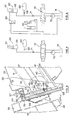
- the combine harvester is generally indicated at 10 and comprises a base unit 12, including crop-treating means (not shown) for separating the desired crop material from the waste crop material, a detachable crop-gathering header 20 located forwardly of the base unit 12, a cab 14 elevated above the header 20 for full view of the crop harvesting process, wheels 16, and a feeder housing 30 for conveying cut crop material from the header 20 rearwardly to the base unit 12 for treatment by the crop-treating means which, for example, can be a conventional threshing unit or the more recently developed rotary type axial flow threshing unit.
- the header 20 includes a cutterbar 22 operable to sever crop material from the stubble.
- a reel 24 disposed above and forwardly of the cutter bar 22 to sweep crop material over the latter and transport it rearwardly to crop consolidating means 26 in the form of a consolidating auger 27.
- the consolidating auger 27 converges crop material towards a centrally disposed crop discharge opening for discharge to the feeder housing structure 30.
- a frame 28 of the header 20 includes a transversely disposed main header beam 29 used to support the header 20 from the feeder housing 30.
- the feeder housing 30 has a forwardly extending, elongated body portion 32 defined by a rearward end 33 pivotally attached to the base unit 12 and a forward end 34 adjacent the header 20 for connection thereto.
- the body portion 32 includes a passageway 36 therethrough, terminating in a crop inlet opening at the forward end 34, for allowing crop material to be transported rearwardly from the forward end 34 to the rearward end 33.
- Crop conveying means 40 in the form of an endless chain and slat apron conveyor 41 is positioned within the passageway 36 and is operable to transport the crop material rearwardly.
- the apron conveyor 41 is driven by a drive shaft 43 positioned at the rearward end 33 and is supported on a driven shaft 44 adjacent the forward end 34.
- a header lift means in the form of a pair of hydraulic actuators 48 interconnecting the feeder housing 30 and the base unit 12.
- actuators 48 By extending the actuators 48 the rearward end 33 of the feeder housing 30 is pivoted about the drive shaft 43 whereby the header 20 is lifted from the ground without significantly changing the discharge point of the apron conveyor 41 relative to the base unit 12.
- These hydraulic actuators 48 may be part either of an automatic header height control mechanism of any type known in the art or of a header weight compensation mechanism equally known in the art.
- FIG. 3 an enlarged view of the forward end 34 of the feeder housing 30 showing a front face member 50 and a detached header 20 in phantom proximate thereto, can be seen.
- the front face member 50 includes an offset section 53 substantially registrable with the main header beam 29 for detachably supporting the header 20 in an operable position on a cradle 58 still to be described hereafter.
- a lateral flotation system 57 for the header is best seen in Figure 3 and comprises the cradle 58 already mentioned and which is pivotally attached to the front face member 50 at the forward end 34 of the feeder housing 30 by a pivot pin 59.
- the cradle 58 comprises a nesting portion 64 for the main header beam 29 at a position generally within the offset section 53 of the front member 50.
- the components so far described are similar to those of the combine harvester illustrated in US-A 4 253 295 to which reference is made and which discloses further details of construction which are not relevant to the present invention.
- the flotation mechanism 57 further comprises a hydraulic actuator 60 which, in the preferred embodiment, is of the single acting type and the rod 61 of which is pivotally attached to the cradle 58 by a pin 62 extending between a pair of lugs 63 depending from the nesting portion 64 of the cradle 58 which releasably receives the main header beam 29.
- the cylinder 65 of the actuator 60 is pivotally attached by a pin 66 to a bracket 67 fixed to, and extending rearwardly from the front face member 50 of the feeder housing 30 at the forward end 34 thereof and against which the lower portion of the cradle 58 is movably supported.
- the header 20 is firmly coupled to the cradle 58 for being transversely pivotable therewith after the main beam 29 of the header 20 is positioned in the nesting portion 64 of the cradle 58.
- the actuator 60 is thus effectively connected between the main body 12 of the machine and the header 20, the actuator 60 being disposed at the side of the feeder housing 30 corresponding to the side of the header 20 at which the header drive is fitted, i.e. at the side of the imbalance.
- the actuator 60 is connected hydraulically via a restrictor 68 to an energy storage device in the form of an accumulator 69 (mounted below the cab 14) and also connected, via a restrictor 71, to a three-position spool valve 72 to which is connected a hydraulic pump 73 for the system and a connection to tank 74.
- the pump 73 In the central position of the valve 72 (the position illustrated) the pump 73 is vented directly to the tank 74 and the actuator 60 is only connected to the accumulator 69. If the valve spool is moved to the right as seen in Figure 4, the actuator 60 is vented to the tank 74 and if it is moved to the left, the actuator is subjected to system pressure from the pump 73.
- the pressure in the accumulator 69 is higher than that in the actuator 60. Preferably this difference is in the range of 10 bar. It also should be noted that the flotation system thus described is totally independent from the header lifting system although it may be used in combination with an automatic header control mechanism. It even may be used in combination with a header weight compensation mechanism altough the combination with an automatic header height control mechanism is preferred.
- the feeder 30 can be set at any required height relative to the ground, including at a height whereat the header 20 makes contact with the ground, by operating the actuators 48 accordingly.
- the header 20 then of course should be positioned to contact the ground surface.
- the operator also actuates the valve 72 to pressurize the hydraulic flotation circuitry normally so as to position the header 20 in its nominal or level position relative to the base unit 12.
- an operating pressure is established in the actuator 60 which is sufficient to pivot the header 20 away from its rest position towards the intermediate nominal position and thus, which compensates the header imbalance.
- the header 20 is positioned in an inclined position with the rod 61 fully retracted within the cylinder 65 of the actuator 60 and with the end of the header 20 supporting the header drive means (i.e. the end of the header 20 at which the imbalance is situated) being situated at a level below the other end due to the header imbalance.
- the operating pressure thus established in the actuator 60 is less than the gas pressure in the hydro-pneumatic accumulator 69 whereby the above described initial setting of the header does not vary the gas volume in the accumulator 69 which thus fills the entire accumulator body.
- the machine moves forwardly and commences harvesting in the conventional manner.
- a transverse irregularity in the ground which may be a temporary transversely offset obstruction of a transverse slope, for example
- one side of the header will rise and the opposite side will drop in view of the pivotal mounting of the cradle 58 about the pivot 59 so as to permit the header 20 to move over and clear said irregularity.
- this pivotal movement of the header 20 is such as to move the rod 61 of the actuator 60 into the cylinder 65 (i.e. the actuator 60 contracts) the fluid thus forced out of the cylinder is forced into the accumulator 69 and increases the pressure therein as the connection to the tank 74 is blocked by the central valve position.
- the header 20 will pivot back to its former (nominal) position under the pressure of the accumulator 69, which is sufficient to overcome any frictional resistance in the pivotal mounting of the header.
- the gas in the accumulator expands until it fills the accumulator volume completely again and thus until all pressure fluid, which previously was urged into the accumulator by the irregularity, is urged back to the flotation actuator 60.
- the header 20 always is returned to the same nominal position as initially set by the operator when the header 20 has cleared the obstruction.
- the actuator 60 is extended as the rod 61 is pulled out of the cylinder 65 and a partial vacuum is created therein (a breather valve may be fitted if desired in this respect).
- This vacuum is created because the accumulator 69 is unable, because of its nominal setting, to urge more hydraulic pressure fluid into the actuator 60 to the extent that the gas in the accumulator 69 already occupies the entire volume of the accumulator 69.
- These returning forces are sufficiently large to overcome any frictional resistance in the pivotal mounting of the header which inherently is present and which, in prior art arrangements also using a hydro-pneumatic accumulator, prevent the header to return to the nominal position when the deviation from said nominal position is rather small.
- the hydro-pneumatic accumulator has a working pressure which corresponds to the working pressure of the flotation actuator and thus acts mainly to absorb hydraulic pressure fluid urged out of the flotation actuator without substantially varying the working pressure and whereby it becomes a rather "passive” component
- the hydro-pneumatic accumulator according to the present invention is rather “active" in the header flotation operation to the extent that it truely forms a power source in the sense as already described and which is operable to always return the header to the same nominal position even when the deviation therefrom is minimal.
- the operator wishes to set the header 20 at an angle to the nominal horizontal position, he operates the valve 72 to one side or other of the central position so as to pressurise or vent the actuator 60 to give the desired header tilt perhaps to compensate for a permanent irregularity in the field being harvested.
- the restrictor 71 damps header movement so that the latter is controlled.
- restrictor 68 has a stabilizing function as will be readily understood by any one skilled in the art.
- the header is of the type having an imbalance due to the header drive means being provided adjacent one end thereof; this imbalance being used for providing header flotation in one direction.
- the principles of the present invention also can be applied to a fully balanced header (such as e.g. a corn header).
- the header imbalance may be replaced by a spring force provided by spring means extending between the cradle 58 and the feeder housing 30 at the side of the latter opposite to the side at which the actuator 60 is provided.
- spring means are arranged to pivot the cradle 58 with the header 20 thereon in the direction around the pivot 59 so as to retract the rod 61 into the cylinder 65 of the actuator 60.
- the return force acting on the flotation actuator 60 is obtained by a hydraulic coupling of the flotation actuator 60 to the header lifting actuators 48 below the plungers thereof.
- the flotation actuator 60 is of the double acting type and is coupled at its plunger rod side to the header lifting actuators 48; the other side of the flotation actuator 60 being coupled to the hydro-pneumatic accumulator 69 and the valve 72 in the same manner as described in connection with Fig. 4.
- the pressure reigning in the header lifting actuators 48 when the header is in the operative position is communicated to the plunger rod side of the flotation actuator 60 where it causes a return force oriented opposite to the flotation force resulting from the pressure below the plunger thereof and which acts in the same manner as the imbalance of the preferred embodiment and as the resilient return force of the spring means of the second embodiment.
- the arrangement again is such that the work pressure below the plunger of the flotation actuator is less than the gas pressure in the accumulator 69. It will be appreciated that this arrangement operates in the same manner as the preferred embodiment and that therefore a detailed description of the operation is not necessary.
- the hydraulic coupling between the flotation actuator 60 and the header lifting actuators 48 may comprise a two-position spool valve 80 for enabling the operator either to establish the coupling as described in case the harvester is equipped with a balanced header, or to interrupt this coupling in case the harvester is equipped with an unbalanced header, in which case the header imbalance provides the return force as described in connection with Fig. 3.
- the present invention provides a very simple but highly effective header flotation system which suffers none of the disadvantages of known systems in that both the operating height and orientation can be set without difficulty.
- the system is very fast acting, whereby peak loads and high torsional forces on the header and/or front end of the machine to which it is fitted, are avoided. This, in turn results in a structure which is less subject to damages and is carefree. Also, the flotation system is very simple in design as well as in operation and is inexpensive to manufacture.
Landscapes
- Life Sciences & Earth Sciences (AREA)
- Environmental Sciences (AREA)
- Fluid-Pressure Circuits (AREA)
- Lifting Devices For Agricultural Implements (AREA)
- Agricultural Machines (AREA)
Description
- The invention relates to a flotation system for a header of a harvester and although it will be discussed primarily in relation to combine harvesters, it is to be understood that it is applicable to any other type of harvester which employs a header, such as a forage harvester, for example.
- Combine harvesters, particularly the self-propelled type, are equipped to utilise a variety of crop-gathering headers, including headers specifically designed for harvesting corn, cereal grains or soy beans, for example. Normally, these headers are attached to the forward end of a feeder housing which is a structure used to convey crop material from the header to a base unit of the combine harvester for further harvesting treatment. As is shown in U.S. Reissue Patent No. 26 512, the forward end of the feeder housing can be constructed so that the header can be quickly and easily attached thereto. Usually, the feeder housing structure is rectangular in cross section and includes a rectangular crop inlet opening at the forward end which matches with a crop outlet opening of a header attached to the feeder housing.
- With the modern trend of developing headers of increasingly larger sizes, providing a ready capability for the headers to follow the contours of the ground is vital. One type of prior art levelling or flotation mechanism, such as disclosed in US-A 3 981 125, involves the twisting of the feeder housing structure about the generally fore-and-aft extending centreline thereof to effect an associated lateral floating movement of the header. Also hillside combine harvesters have been developed to allow the header to follow slopes of up to 45%. Such hillside combine harvesters have been known to utilise a side pivot mechanism, as disclosed in US-A 3 731 470, or a centre-mounted pivot connection directly between the header and the feeder housing as disclosed in US-A 2 780 903; the latter arrangement involving a specific circular or semi-circular opening between the feeder housing and the header.
- Problems that have been encountered with these prior art lateral float mechanisms include a difficult sealing situation between the feeder housing and the base unit as the feeder housing is twisted relative to the base unit. The twisting of the feeder housing also results in a twisting of the feeder housing drive mechanism, which in turn also increases wear and reduces the life of the drive chains or the like. Another problem encountered is the matching of different types of headers to different feeder housing structures. This problem is particularly relevant to feeder housings having specially shaped crop inlet openings.
- In other known header flotation systems use is made of one or two hydraulic actuators connected between the header and the base unit of a machine to pivot the header in a transverse direction around a generally fore-and-aft pivot axis and which are interconnected hydraulically with a header weight compensation device including control actuators together with a hydro-pneumatic accumulator which effect raising and lowering of the header. In operation, the hydraulic system, inclusive the hydro-pneumatic accumulator is pressurized at an operating pressure such that the ground contact pressure of the header is minimal. This allows the header to follow the irregularities in the ground contour by as well raising or lowering the complete header as by pivoting the header in the transverse direction depending on the size of the irregularities and on the location thereof relative to the header. With headers having a weight imbalance, such as grain headers having the drive means located at one side, a single flotation actuator can be used at the side of the drive means, but with balanced headers, two flotation actuators are used, one at or towards each side of the header.
- US-A 4 527 381 shows a purely mechanical lateral flotation mechanism for a combine header and comprising a pair of counter-acting resilient means in the form of pre-compressed rubber springs which are disposed, on the one hand, to permit the header to laterally float around a nominal position upon the harvester encountering, during operation, obstacles inducing such lateral flotation and, on the other hand, to restore the header in its nominal position upon clearing the obstacles which previously have caused this lateral flotation. For use in combination with a header having a weight imbalance, a single-acting, end-of-stroke hydraulic actuator is provided for installation between the header and the base unit. This actuator is operable to compensate for the weight imbalance and to set the header in its nominal position prior to starting operation. This nominal position normally is the middle position between two extreme positions and no other position can readily be chosen as the nominal position. The hydraulic actuator according to US-A 4 527 381 does not actively take part in the lateral flotational operation of the header; it merely permits such lateral flotational operation after the initial setting of the header in the nominal position. In this respect, it should be noted that retraction of the hydraulic actuator as a result of flotational pivotal movement of the header in one direction, is permitted by virtue of the hydraulic actuator being coupled to the header lift hydraulic power system including a hydro-pneumatic accumulator. This accumulator is pressurized at the working pressure of the header lift hydraulic power system in order to be operable to perform its intended function in this system.
- In still another known header flotation system such as disclosed in US-A 3 386 235, the header is formed in two parts which can pivot independently from each other and relative to the feeder housing around respective fore-and-aft extending pivot axes. These parts also can be raised or lowered in unison together with the feeder housing upon which they are mounted, around a transverse pivot axis. A hydraulic suspension system, including cylinders supporting the feeder housing with the header thereon on the base unit and further cylinders supporting the header portions on the feeder housing, is coupled to a hydraulic control mechanism which is actuated by variations in hydraulic pressure in the respective cylinders in response to corresponding movements of the header, respectively the constituent portions thereof over undulations in the ground. The arrangement is such that said variations in pressure transmitted to the control mechanism cause the control mechanism to allow hydraulic pressure fluid to flow to or from the respective cylinders so as to compensate for said variations and tend to maintain a substantially constant hydraulic pressure in the respective cylinders. Hydro-pneumatic accumulators, operating at the system pressure, are coupled to the various cylinders for assisting in a smooth following of the ground irregularities by the header and the constituent portions thereof.
- With the latter two systems, the header must always be in contact with the ground at least at some point along its length so that these headers cannot be set to operate at a given stubble height, for example, which is a disadvantage. This is not so with an automatic header height and lateral flotation control system such as disclosed in the copending European patent application no. 0 198 544 and which uses sensors on the underside of the header. Such sensors produce electrical signals for controlling the flotation actuators via electro-hydraulic valves, thus making the system automatic. However, other disadvantages arise with such automatic systems, the main one of which is that they are slow acting. Furthermore, these systems are expensive and the sensors thereof can suffer damage when the header encounters a large obstruction and the header tilting is too slow to clear this obstruction smoothly. The slow-acting nature of such automatic systems also can place excessive torsional forces on the header and front end of the machine to which it is fitted (for example the feeder housing of a combine harvester) when the header tilts on meeting an irregularity in the ground and until the system has responded and effected the required flotation to compensate. Although an automatic system can operate with the header off the ground because it is not part of a header weight compensation system, it cannot be set to give any desired initial position of the header which deviates from the nominal position of the header because the electro-hydraulic control valves for the flotation actuators can only be set through the sensors.
- Starting from US-A 4 527 381, it is the objective of the present invention to provide a harvester including a header with a simple but efficient lateral header flotation system which furthermore is very flexible in use.
- According to the present invention, a harvester is provided comprising a mobile base unit, a transversely extending crop harvesting header supported on the base unit for pivotal movement between opposed extreme positions about a generally fore-and-aft axis and, a lateral flotation system for, during operation of the harvester, permitting the header to pivot about said axis for accomodating transversely offset obstacles encountered by the header; said flotation system including:
- - a hydraulic actuator operatively coupled between the header and the base unit for pivoting the header away from one of said extreme positions to position the header in a nominal position intermediate said opposed extreme positions prior to starting flotation operation;
- - return means urging the header to pivot in the direction opposite to the pivotal movement induced by the hydraulic actuator; and
- - a hydro-pneumatic accumulator operatively coupled to the hydraulic actuator, the arrangement being such that:
- - upon the header encountering an obstacle tending to pivot said header away from its nominal position in the same direction as the return means, said header is permitted to pivot in this direction thereby causing the hydraulic actuator to retract and the gas in the hydro-pneumatic accumulator to be compressed to store energy; said energy subsequently being released back to the hydraulic actuator to restore the header to its nominal position upon clearing said obstacle, and
- - upon the header encountering an obstacle tending to pivot said header away from its nominal position in the opposite direction, said header is permitted to pivot in said opposite direction without however changing the gas volume in the hydro-pneumatic accumulator and subsequently, after clearing said obstacle, is restored in its nominal position by the return means.
- This harvester is characterized in that the hydro-pneumatic accumulator is pressurized at a pressure which exceeds the working pressure reigning in the hydraulic actuator when the header is in its nominal position and encounters no obstacle so that thereby the gas in the hydro-pneumatic accumulator occupies the entire volume thereof.
- A self-propelled combine harvester incorporating the present invention will now be described in greater detail, by way of example, with reference to the accompanying drawings, in which:
- Figure 1 is a front elevational view of the self-propelled combine harvester having a grain header attached thereto, with certain components broken away,
- Figure 2 is a cross-sectional view of the forward portion of the combine harvester including the header and feeder housing, taken along the line II-II of Figure 1,
- Figure 3 is a side elevational view, to a larger scale, of the forward portion of the feeder housing,
- Figure 4 is a hydraulic circuit diagram of the header flotation system in accordance with the invention, and
- Figure 5 is a view similar to Figure 4 but showing an alternative arrangement.
- Referring to Figures 1 and 3 of the drawings, left hand and right-hand references are used as a matter of convenience and are determined by standing at the rear of the machine and facing the forward direction of travel. The combine harvester is generally indicated at 10 and comprises a
base unit 12, including crop-treating means (not shown) for separating the desired crop material from the waste crop material, a detachable crop-gathering header 20 located forwardly of thebase unit 12, acab 14 elevated above theheader 20 for full view of the crop harvesting process,wheels 16, and afeeder housing 30 for conveying cut crop material from theheader 20 rearwardly to thebase unit 12 for treatment by the crop-treating means which, for example, can be a conventional threshing unit or the more recently developed rotary type axial flow threshing unit. - Referring now to the cross-sectional view of Figure 2, a more detailed view of the general inner workings of the
header 20 and thefeeder housing 30 can be seen. Theheader 20 includes acutterbar 22 operable to sever crop material from the stubble. Areel 24 disposed above and forwardly of thecutter bar 22 to sweep crop material over the latter and transport it rearwardly to crop consolidating means 26 in the form of a consolidatingauger 27. The consolidatingauger 27 converges crop material towards a centrally disposed crop discharge opening for discharge to thefeeder housing structure 30. Aframe 28 of theheader 20 includes a transversely disposedmain header beam 29 used to support theheader 20 from thefeeder housing 30. - As can also be seen in Figure 2, the
feeder housing 30 has a forwardly extending,elongated body portion 32 defined by arearward end 33 pivotally attached to thebase unit 12 and aforward end 34 adjacent theheader 20 for connection thereto. Thebody portion 32 includes apassageway 36 therethrough, terminating in a crop inlet opening at theforward end 34, for allowing crop material to be transported rearwardly from theforward end 34 to therearward end 33. Crop conveying means 40 in the form of an endless chain andslat apron conveyor 41 is positioned within thepassageway 36 and is operable to transport the crop material rearwardly. Theapron conveyor 41 is driven by adrive shaft 43 positioned at therearward end 33 and is supported on a drivenshaft 44 adjacent theforward end 34. The height of theheader 20 relative to the ground is controlled by a header lift means in the form of a pair ofhydraulic actuators 48 interconnecting thefeeder housing 30 and thebase unit 12. By extending theactuators 48 therearward end 33 of thefeeder housing 30 is pivoted about thedrive shaft 43 whereby theheader 20 is lifted from the ground without significantly changing the discharge point of theapron conveyor 41 relative to thebase unit 12. Thesehydraulic actuators 48 may be part either of an automatic header height control mechanism of any type known in the art or of a header weight compensation mechanism equally known in the art. - Referring now to Figure 3, an enlarged view of the
forward end 34 of thefeeder housing 30 showing afront face member 50 and adetached header 20 in phantom proximate thereto, can be seen. Thefront face member 50 includes an offsetsection 53 substantially registrable with themain header beam 29 for detachably supporting theheader 20 in an operable position on acradle 58 still to be described hereafter. - A
lateral flotation system 57 for the header is best seen in Figure 3 and comprises thecradle 58 already mentioned and which is pivotally attached to thefront face member 50 at theforward end 34 of thefeeder housing 30 by apivot pin 59. Thecradle 58 comprises anesting portion 64 for themain header beam 29 at a position generally within the offsetsection 53 of thefront member 50. The components so far described are similar to those of the combine harvester illustrated in US-A 4 253 295 to which reference is made and which discloses further details of construction which are not relevant to the present invention. - In accordance with the present invention, the
flotation mechanism 57 further comprises ahydraulic actuator 60 which, in the preferred embodiment, is of the single acting type and therod 61 of which is pivotally attached to thecradle 58 by apin 62 extending between a pair oflugs 63 depending from thenesting portion 64 of thecradle 58 which releasably receives themain header beam 29. Thecylinder 65 of theactuator 60 is pivotally attached by apin 66 to abracket 67 fixed to, and extending rearwardly from thefront face member 50 of thefeeder housing 30 at theforward end 34 thereof and against which the lower portion of thecradle 58 is movably supported. Theheader 20 is firmly coupled to thecradle 58 for being transversely pivotable therewith after themain beam 29 of theheader 20 is positioned in thenesting portion 64 of thecradle 58. Theactuator 60 is thus effectively connected between themain body 12 of the machine and theheader 20, theactuator 60 being disposed at the side of thefeeder housing 30 corresponding to the side of theheader 20 at which the header drive is fitted, i.e. at the side of the imbalance. - As can best be seen in Figure 4, the
actuator 60 is connected hydraulically via a restrictor 68 to an energy storage device in the form of an accumulator 69 (mounted below the cab 14) and also connected, via arestrictor 71, to a three-position spool valve 72 to which is connected ahydraulic pump 73 for the system and a connection totank 74. In the central position of the valve 72 (the position illustrated) thepump 73 is vented directly to thetank 74 and theactuator 60 is only connected to theaccumulator 69. If the valve spool is moved to the right as seen in Figure 4, theactuator 60 is vented to thetank 74 and if it is moved to the left, the actuator is subjected to system pressure from thepump 73. It should be noted that, under normal operating conditions, the pressure in theaccumulator 69 is higher than that in theactuator 60. Preferably this difference is in the range of 10 bar. It also should be noted that the flotation system thus described is totally independent from the header lifting system although it may be used in combination with an automatic header control mechanism. It even may be used in combination with a header weight compensation mechanism altough the combination with an automatic header height control mechanism is preferred. - In operation of the machine and provided the
hydraulic actuators 48 are not part of a header weight compensation mechanism, thefeeder 30 can be set at any required height relative to the ground, including at a height whereat theheader 20 makes contact with the ground, by operating theactuators 48 accordingly. In the event thehydraulic actuators 48 are part of a header weight compensation mechanism, theheader 20 then of course should be positioned to contact the ground surface. - Additionally and prior to commencing operation, the operator also actuates the
valve 72 to pressurize the hydraulic flotation circuitry normally so as to position theheader 20 in its nominal or level position relative to thebase unit 12. By doing so, an operating pressure is established in theactuator 60 which is sufficient to pivot theheader 20 away from its rest position towards the intermediate nominal position and thus, which compensates the header imbalance. Indeed, without this pressurizing, theheader 20 is positioned in an inclined position with therod 61 fully retracted within thecylinder 65 of theactuator 60 and with the end of theheader 20 supporting the header drive means (i.e. the end of theheader 20 at which the imbalance is situated) being situated at a level below the other end due to the header imbalance. As already mentioned, the operating pressure thus established in theactuator 60 is less than the gas pressure in the hydro-pneumatic accumulator 69 whereby the above described initial setting of the header does not vary the gas volume in theaccumulator 69 which thus fills the entire accumulator body. - Once the operating position of the
header 20 has been set, the machine moves forwardly and commences harvesting in the conventional manner. Should theheader 20 meet a transverse irregularity in the ground, which may be a temporary transversely offset obstruction of a transverse slope, for example, then one side of the header will rise and the opposite side will drop in view of the pivotal mounting of thecradle 58 about thepivot 59 so as to permit theheader 20 to move over and clear said irregularity. Assuming this pivotal movement of theheader 20 is such as to move therod 61 of theactuator 60 into the cylinder 65 (i.e. theactuator 60 contracts) the fluid thus forced out of the cylinder is forced into theaccumulator 69 and increases the pressure therein as the connection to thetank 74 is blocked by the central valve position. If the irregularity is only temporary, then when it is cleared by theheader 20, the latter will pivot back to its former (nominal) position under the pressure of theaccumulator 69, which is sufficient to overcome any frictional resistance in the pivotal mounting of the header. The gas in the accumulator expands until it fills the accumulator volume completely again and thus until all pressure fluid, which previously was urged into the accumulator by the irregularity, is urged back to theflotation actuator 60. Thus, theheader 20 always is returned to the same nominal position as initially set by the operator when theheader 20 has cleared the obstruction. - Should the
header 20 pivot in the opposite direction, theactuator 60 is extended as therod 61 is pulled out of thecylinder 65 and a partial vacuum is created therein (a breather valve may be fitted if desired in this respect). This vacuum is created because theaccumulator 69 is unable, because of its nominal setting, to urge more hydraulic pressure fluid into theactuator 60 to the extent that the gas in theaccumulator 69 already occupies the entire volume of theaccumulator 69. When theheader 20 is free to return to its former position, it does so under the weight imbalance of the header in the illustrated embodiment, this weight imbalance equally being sufficient to overcome any frictional resistance in the pivotal mounting of theheader 20, whereby also starting from this side of the nominal position, the header always is returned to its nominal setting when the ground surface beneath the header permits this. - From what precedes, it will be understood that the hydro-
pneumatic accumulator 69 as used in the present invention on the one hand and the header imbalance on the other hand effectively act as "power sources" for always returning, without any hesitation, theheader 20 back to the same nominal position previously set by the operator when the ground surface below theheader 20 permits this to happen, i.e. when any irregularities in the ground have been cleared by the header. These returning forces are sufficiently large to overcome any frictional resistance in the pivotal mounting of the header which inherently is present and which, in prior art arrangements also using a hydro-pneumatic accumulator, prevent the header to return to the nominal position when the deviation from said nominal position is rather small. Unlike in these prior art arrangements where the hydro-pneumatic accumulator has a working pressure which corresponds to the working pressure of the flotation actuator and thus acts mainly to absorb hydraulic pressure fluid urged out of the flotation actuator without substantially varying the working pressure and whereby it becomes a rather "passive" component, the hydro-pneumatic accumulator according to the present invention, is rather "active" in the header flotation operation to the extent that it truely forms a power source in the sense as already described and which is operable to always return the header to the same nominal position even when the deviation therefrom is minimal. - If the operator wishes to set the
header 20 at an angle to the nominal horizontal position, he operates thevalve 72 to one side or other of the central position so as to pressurise or vent theactuator 60 to give the desired header tilt perhaps to compensate for a permanent irregularity in the field being harvested. When this control of theheader 20 is being exercised, therestrictor 71 damps header movement so that the latter is controlled. Also restrictor 68 has a stabilizing function as will be readily understood by any one skilled in the art. - In the preferred embodiment as described above, the header is of the type having an imbalance due to the header drive means being provided adjacent one end thereof; this imbalance being used for providing header flotation in one direction. However, the principles of the present invention also can be applied to a fully balanced header (such as e.g. a corn header). In this case the header imbalance may be replaced by a spring force provided by spring means extending between the
cradle 58 and thefeeder housing 30 at the side of the latter opposite to the side at which theactuator 60 is provided. These spring means are arranged to pivot thecradle 58 with theheader 20 thereon in the direction around thepivot 59 so as to retract therod 61 into thecylinder 65 of theactuator 60. - In a further embodiment shown in Fig. 5, the return force acting on the
flotation actuator 60 is obtained by a hydraulic coupling of theflotation actuator 60 to theheader lifting actuators 48 below the plungers thereof. In this case, theflotation actuator 60 is of the double acting type and is coupled at its plunger rod side to theheader lifting actuators 48; the other side of theflotation actuator 60 being coupled to the hydro-pneumatic accumulator 69 and thevalve 72 in the same manner as described in connection with Fig. 4. The pressure reigning in theheader lifting actuators 48 when the header is in the operative position, is communicated to the plunger rod side of theflotation actuator 60 where it causes a return force oriented opposite to the flotation force resulting from the pressure below the plunger thereof and which acts in the same manner as the imbalance of the preferred embodiment and as the resilient return force of the spring means of the second embodiment. The arrangement again is such that the work pressure below the plunger of the flotation actuator is less than the gas pressure in theaccumulator 69. It will be appreciated that this arrangement operates in the same manner as the preferred embodiment and that therefore a detailed description of the operation is not necessary. - Finally, the hydraulic coupling between the
flotation actuator 60 and theheader lifting actuators 48 may comprise a two-position spool valve 80 for enabling the operator either to establish the coupling as described in case the harvester is equipped with a balanced header, or to interrupt this coupling in case the harvester is equipped with an unbalanced header, in which case the header imbalance provides the return force as described in connection with Fig. 3. - It will be seen that the present invention provides a very simple but highly effective header flotation system which suffers none of the disadvantages of known systems in that both the operating height and orientation can be set without difficulty. This means that the header can still be operated in a weight compensation mode if desired. This also means that, if the header is set to operate at a height above the ground and thus, if there is no permanent contact of the header with the ground, the header nevertheless always returns to the same nominal position previously set by the operator after the header having cleared an obstruction. This would not be the case in prior art arrangements equipped with a hydro-pneumatic accumulator to the extent that this accumulator in these arrangements does not provide enough power to overcome frictional resistance in the pivotal mounting of the header when the deviation from the nominal position is minimal.
- Furthermore, the system is very fast acting, whereby peak loads and high torsional forces on the header and/or front end of the machine to which it is fitted, are avoided. This, in turn results in a structure which is less subject to damages and is carefree. Also, the flotation system is very simple in design as well as in operation and is inexpensive to manufacture.
Claims (15)
said harvester being characterized in that the hydro-pneumatic accumulator (69) is pressurized at a pressure which exceeds the working pressure reigning in the hydraulic actuator (60) when the header (20) is in its nominal position and encounters no obstacle so that thereby the gas in the hydro-pneumatic accumulator (69) occupies the entire volume thereof.
Priority Applications (4)
| Application Number | Priority Date | Filing Date | Title |
|---|---|---|---|
| EP86200764A EP0243540B1 (en) | 1986-05-02 | 1986-05-02 | Header flotation system for an agricultural machine |
| DE8686200764T DE3673519D1 (en) | 1986-05-02 | 1986-05-02 | MACHINE TABLE VIBRATION DEVICE FOR AGRICULTURAL MACHINE. |
| US07/043,896 US4733523A (en) | 1986-05-02 | 1987-04-29 | Header flotation system for an agricultural machine |
| CA000536161A CA1287222C (en) | 1986-05-02 | 1987-05-01 | Header flotation system for an agricultural machine |
Applications Claiming Priority (1)
| Application Number | Priority Date | Filing Date | Title |
|---|---|---|---|
| EP86200764A EP0243540B1 (en) | 1986-05-02 | 1986-05-02 | Header flotation system for an agricultural machine |
Publications (2)
| Publication Number | Publication Date |
|---|---|
| EP0243540A1 EP0243540A1 (en) | 1987-11-04 |
| EP0243540B1 true EP0243540B1 (en) | 1990-08-16 |
Family
ID=8195735
Family Applications (1)
| Application Number | Title | Priority Date | Filing Date |
|---|---|---|---|
| EP86200764A Expired EP0243540B1 (en) | 1986-05-02 | 1986-05-02 | Header flotation system for an agricultural machine |
Country Status (3)
| Country | Link |
|---|---|
| US (1) | US4733523A (en) |
| EP (1) | EP0243540B1 (en) |
| DE (1) | DE3673519D1 (en) |
Cited By (1)
| Publication number | Priority date | Publication date | Assignee | Title |
|---|---|---|---|---|
| EP1145619A1 (en) | 2000-04-12 | 2001-10-17 | CLAAS Selbstfahrende Erntemaschinen GmbH | Harvesting machine for hillside working |
Families Citing this family (65)
| Publication number | Priority date | Publication date | Assignee | Title |
|---|---|---|---|---|
| US4982762A (en) * | 1989-03-15 | 1991-01-08 | Deere & Company | Hydraulic lift with weight transfer |
| US4920732A (en) * | 1989-03-15 | 1990-05-01 | Deere & Company | Hydraulic lift with weight transfer |
| US5415586A (en) * | 1993-11-17 | 1995-05-16 | R. A. Hanson Company, Inc. | Combine harvester leveling system, combine harvester header adjusting system, and pivoting chain drive system |
| US5471825A (en) * | 1994-06-24 | 1995-12-05 | Case Corporation | Combine head position control system with float override |
| US5577373A (en) * | 1994-06-24 | 1996-11-26 | Case Corporation | Agricultural vehicle including a system for automatically moving an implement and improved ground height sensing to a predetermined operating position |
| US5471823A (en) * | 1994-06-24 | 1995-12-05 | Case Corporation | Electronic combine head float control system |
| DE19508887C2 (en) * | 1995-03-11 | 1999-01-07 | Claas Ohg | Self-propelled harvesting machine with two-part cutting trough |
| US5799483A (en) * | 1996-08-29 | 1998-09-01 | Voss; Douglas A. | Combine harvester header lateral levelling |
| US5918448A (en) * | 1997-02-06 | 1999-07-06 | Agco Corporation | Combine header lateral tilt assembly |
| US5927054A (en) * | 1997-06-13 | 1999-07-27 | Fmc Corporation | Corn head with variable angle harvesting |
| DE19823347A1 (en) * | 1998-05-13 | 1999-11-18 | Claas Ohg | Device for the control and adjustment of working cylinders |
| US6041583A (en) * | 1998-11-16 | 2000-03-28 | Deere & Company | Height sensing system for a harvester head |
| US6260936B1 (en) | 1999-10-12 | 2001-07-17 | Tab Products Company, Inc. | Operator interface for mobile carriage |
| US6568161B1 (en) | 2001-11-15 | 2003-05-27 | New Holland North America, Inc. | User interface for a harvesting machine |
| US6735929B2 (en) * | 2002-03-18 | 2004-05-18 | Deere & Company | Multifunction latch for a combine |
| US7168226B2 (en) * | 2004-03-31 | 2007-01-30 | Cnh America Llc | Independent hydraulic header lift and flotation system |
| US6901729B1 (en) | 2004-03-31 | 2005-06-07 | Cnh America Llc | Header lift system with hydraulic counterweight |
| US7869922B2 (en) * | 2004-04-12 | 2011-01-11 | Cnh America Llc | Method and apparatus to put a windrower header in the transport mode under specified conditions |
| US7703266B2 (en) * | 2004-04-12 | 2010-04-27 | Cnh America Llc | Method for managing the electrical control system of a windrower header flotation and lift system |
| US7555883B2 (en) * | 2004-04-12 | 2009-07-07 | Cnh America Llc | System and method for managing the electrical control system of a windrower header flotation and lift system |
| US7191582B2 (en) * | 2005-05-10 | 2007-03-20 | Deere & Company | Header terrain following system |
| US7207164B2 (en) * | 2005-05-10 | 2007-04-24 | Deere & Company | Header hydraulic float suspension |
| US7222475B2 (en) * | 2005-05-10 | 2007-05-29 | Deere & Company | Header hydraulic float system |
| US7430846B2 (en) * | 2005-05-10 | 2008-10-07 | Deere & Company | Floating header with integrated float system for use with an agricultural windrower or combine |
| US20070012010A1 (en) * | 2005-07-14 | 2007-01-18 | Otto Douglas R | Method and apparatus for controlling a windrower header flotation system during removal of the header |
| US7168229B1 (en) * | 2005-07-14 | 2007-01-30 | Cnh America Llc | Drop rate control for agricultural header |
| US20080271426A1 (en) * | 2006-02-10 | 2008-11-06 | Agco Corporation | Draper belt with crop-retaining rib |
| US20070193243A1 (en) * | 2006-02-10 | 2007-08-23 | Schmidt James R | Combine Harvester Draper Header Having Flexible Cutterbar |
| US20080276590A1 (en) * | 2006-02-10 | 2008-11-13 | Agco Corporation | Flexible draper and cutter bar with tilt arm for cutterbar drive |
| US7478521B2 (en) * | 2006-03-02 | 2009-01-20 | Deere & Company | Flexible cutting platform to follow ground contour in an agricultural harvesting machine |
| US7596935B2 (en) * | 2007-10-30 | 2009-10-06 | Vermeer Manufacturing Company | Suspension system for a floating header on an agricultural implement |
| US20090266044A1 (en) | 2008-04-25 | 2009-10-29 | Coers Bruce A | Integrated draper belt support and skid shoe in an agricultural harvesting machine |
| US20090277144A1 (en) * | 2008-05-09 | 2009-11-12 | Agco Corporation | Spring flotation for center deck of draper header |
| US7886511B2 (en) | 2008-05-09 | 2011-02-15 | Agco Corporation | Draper head with flexible cutterbar having rigid center section |
| WO2009136272A1 (en) * | 2008-05-09 | 2009-11-12 | Agco Corporation | Adjustable cutterbar travel range for a flexible cutterbar header |
| US20090277145A1 (en) | 2008-05-09 | 2009-11-12 | Agco Corporation | Header height control system with multiple potentiometer input |
| ATE538637T1 (en) * | 2008-05-09 | 2012-01-15 | Agco Corp | CENTER HARVEST GUIDE DEVICE FOR CONVEYOR BELT ATTACHMENT |
| US7921627B2 (en) | 2008-05-09 | 2011-04-12 | Agco Corporation | Interlocking belt guards for a draper header |
| US20090277148A1 (en) * | 2008-05-09 | 2009-11-12 | Agco Corporation | Flexible draper and cutter bar having shiftable crop divider with deflector |
| US7870709B2 (en) * | 2009-02-25 | 2011-01-18 | Chn America Llc | Automatic lateral tilt control of a header in stubble height mode using machine level sensor |
| US8635842B2 (en) | 2009-08-05 | 2014-01-28 | Kevin Markt | Flexible row crop header for an agricultural harvester |
| DE102010028605A1 (en) * | 2010-05-05 | 2011-11-10 | Deere & Company | Drive arrangement for a header of a harvester |
| US8205421B2 (en) | 2010-06-16 | 2012-06-26 | Agco Corporation | Belt guard crop dam for flexible draper header |
| US7958711B1 (en) | 2010-06-16 | 2011-06-14 | Agco Corporation | Crop deflector for ends of draper belt of flexible draper header |
| US8943788B2 (en) | 2010-10-14 | 2015-02-03 | Intelligent Agricultural Solutions, Llc | Harvester with automatic depth and level control |
| BE1020181A3 (en) * | 2011-07-20 | 2013-06-04 | Cnh Belgium Nv | LIFTING SYSTEM FOR HARVESTING MACHINE. |
| US8745964B2 (en) * | 2011-11-16 | 2014-06-10 | Macdon Industries Ltd | Swather with float assembly and disconnect coupling |
| US8479483B1 (en) | 2011-12-27 | 2013-07-09 | Agco Corporation | Flexible draper head providing reduced crop residue accumulation |
| US8966871B2 (en) * | 2011-12-28 | 2015-03-03 | Agco Corporation | Automatic roll-back and return-to-position for header tilt on an agricultural machine |
| WO2013101863A1 (en) * | 2011-12-28 | 2013-07-04 | Agco Corporation | Fore and aft tilt for corn header |
| US9532497B2 (en) * | 2012-05-02 | 2017-01-03 | Agco Corporation | Variable precharge accumulator for agricultural header |
| DE102012223770A1 (en) * | 2012-12-19 | 2014-06-26 | Deere & Company | Inclined conveyor assembly with flexible bottom |
| DE102012223769A1 (en) | 2012-12-19 | 2014-06-26 | Deere & Company | Inclined conveyor assembly with improved swing axle |
| US9844184B2 (en) * | 2015-03-17 | 2017-12-19 | Agco Corporation | Header position sensing system for an agricultural harvester |
| BE1022917B1 (en) * | 2015-05-29 | 2016-10-17 | Cnh Industrial Belgium Nv | Structure for carrying the mower of a combine harvester |
| US10624263B2 (en) * | 2016-06-21 | 2020-04-21 | Macdon Industries Ltd | Crop machine with an electronically controlled hydraulic cylinder flotation system |
| BR102017010857A2 (en) * | 2017-05-24 | 2018-12-18 | CNH Industrial Brasil Ltda. | structural assembly for mounting a platform and harvester |
| US10568264B2 (en) * | 2017-12-20 | 2020-02-25 | Cnh Industrial America Llc | Harvester with header lift assembly |
| US11259463B1 (en) * | 2018-10-04 | 2022-03-01 | Harper Industries, Inc. | Slope mower with automatic leveling suspension and system for maintaining vertical orientation of mower body |
| US11272659B2 (en) * | 2019-03-27 | 2022-03-15 | Deere & Company | Controlled or tuned float on an agricultural harvester to modify float response |
| US11191212B2 (en) | 2019-04-23 | 2021-12-07 | Deere & Company | Controlled float on an agricultural harvester for header leveling |
| US11219162B2 (en) | 2019-04-23 | 2022-01-11 | Deere & Company | Controlled header lowering on an agricultural harvester |
| US11224164B2 (en) | 2019-04-23 | 2022-01-18 | Deere & Company | Damped float response on an agricultural harvester |
| US11497164B2 (en) * | 2019-10-22 | 2022-11-15 | Cnh Industrial America Llc | Header suspension for pivoting header of combine harvester |
| US12532808B2 (en) * | 2022-06-24 | 2026-01-27 | Cnh Industrial America Llc | Passive header tilt control for rigid-mode operation with friction-controlling cylinders |
Family Cites Families (18)
| Publication number | Priority date | Publication date | Assignee | Title |
|---|---|---|---|---|
| US2750728A (en) * | 1951-06-20 | 1956-06-19 | Harris Mfg Company | Sealing assembly for the header mount of a sidehill harvester |
| US2753675A (en) * | 1952-03-24 | 1956-07-10 | Massey Harris Ferguson Inc | Combine having side hill platform mounting and adjusting means |
| US2780903A (en) * | 1952-12-22 | 1957-02-12 | Deere & Co | Platform adjusting means for sidehill harvesters |
| US2821059A (en) * | 1954-04-01 | 1958-01-28 | Deere & Co | Hillside harvester |
| US2796717A (en) * | 1954-11-01 | 1957-06-25 | Internaltional Harvester Compa | Hillside harvester thresher |
| US2800760A (en) * | 1954-12-31 | 1957-07-30 | Case Co J I | Combine header tilt device |
| US3008724A (en) * | 1959-11-09 | 1961-11-14 | Massey Ferguson Inc | Leveling control for hillside combines |
| US3386235A (en) * | 1964-09-29 | 1968-06-04 | Texas Industries Inc | Agricultural machines |
| DE1507164A1 (en) * | 1966-07-07 | 1970-01-02 | Bosch Gmbh Robert | Hydraulic lifting device on combine harvesters |
| DK135873B (en) * | 1970-07-09 | 1977-07-11 | Agrostroj Prostejov Np | Coupling mechanism between a mowing table and the grain conveyor located behind it. |
| CS149501B1 (en) * | 1971-06-07 | 1973-07-25 | ||
| US3717995A (en) * | 1971-10-12 | 1973-02-27 | Hesston Corp | Hydraulic flotation for implement header |
| AT343395B (en) * | 1974-07-12 | 1978-05-26 | Aebi & Co Ag | HYDRAULIC LIFTING AND LOWERING DEVICE FOR THE WORK EQUIPMENT OF A COMMERCIAL VEHICLE |
| US3981125A (en) * | 1975-02-12 | 1976-09-21 | International Harvester Company | Leveling mechanism for harvester headers |
| US4266395A (en) * | 1979-07-09 | 1981-05-12 | Thomas W. Basham | Apparatus to permit and control tilting of the header portion of a combine relative to the throat portion thereof about the axis of forward travel of the combine |
| US4253295A (en) * | 1979-11-05 | 1981-03-03 | Sperry Corporation | Lateral float mechanism for combines |
| US4266391A (en) * | 1979-11-05 | 1981-05-12 | Sperry Corporation | Header attachment mechanism for combines |
| US4527381A (en) * | 1983-10-13 | 1985-07-09 | Sperry Corporation | Lateral flotation mechanism for combine harvesters |
-
1986
- 1986-05-02 DE DE8686200764T patent/DE3673519D1/en not_active Expired - Lifetime
- 1986-05-02 EP EP86200764A patent/EP0243540B1/en not_active Expired
-
1987
- 1987-04-29 US US07/043,896 patent/US4733523A/en not_active Expired - Lifetime
Cited By (2)
| Publication number | Priority date | Publication date | Assignee | Title |
|---|---|---|---|---|
| EP1145619A1 (en) | 2000-04-12 | 2001-10-17 | CLAAS Selbstfahrende Erntemaschinen GmbH | Harvesting machine for hillside working |
| US6510680B2 (en) | 2000-04-12 | 2003-01-28 | Claas Selbstfahrende Erntemaschinen Gmbh | Apparatus and method for pivotal adjustment of a frontal attachment in an agricultural machine |
Also Published As
| Publication number | Publication date |
|---|---|
| EP0243540A1 (en) | 1987-11-04 |
| DE3673519D1 (en) | 1990-09-20 |
| US4733523A (en) | 1988-03-29 |
Similar Documents
| Publication | Publication Date | Title |
|---|---|---|
| EP0243540B1 (en) | Header flotation system for an agricultural machine | |
| EP3473076B1 (en) | Self-contained combine draper wing leveler | |
| CA2551309C (en) | Suspension system for a belt pickup header in an agricultural harvester | |
| US5327709A (en) | Adjustable header flotation mechanism | |
| US7430846B2 (en) | Floating header with integrated float system for use with an agricultural windrower or combine | |
| EP2156725B1 (en) | Header float system for use with an agricultural windrower or combine | |
| CN111820010A (en) | Controlled header drop on agricultural harvesters | |
| US11497164B2 (en) | Header suspension for pivoting header of combine harvester | |
| US4573308A (en) | Harvesting platform with a floating cutterbar | |
| US4206582A (en) | Header lift arrangement for windrowers | |
| CN111819991A (en) | Controlled float for header leveling on agricultural harvesters | |
| CA2624556C (en) | Floating header with integrated float system for use with an agricultural windrower or combine | |
| US3623304A (en) | Hydraulic system for supporting a harvester platform | |
| EP3811763B1 (en) | Cutter bar support linkage | |
| US12484481B2 (en) | Headland grain capture sequence for agricultural vehicle header | |
| EP0286736B1 (en) | Header flotation system for an agricultural machine | |
| US5178402A (en) | Leveling assembly for a vehicle | |
| US3474607A (en) | Self-propelled windrower | |
| CA1287222C (en) | Header flotation system for an agricultural machine | |
| US20240397867A1 (en) | Biasing mechanism for header tilt on a center-pivot mower | |
| JPH06907Y2 (en) | All culm-type companion | |
| JPH0530602Y2 (en) | ||
| JPH0525386Y2 (en) | ||
| CA2040532C (en) | Support linkage for mounting a header on a support frame | |
| JP2008017761A (en) | Combine |
Legal Events
| Date | Code | Title | Description |
|---|---|---|---|
| PUAI | Public reference made under article 153(3) epc to a published international application that has entered the european phase |
Free format text: ORIGINAL CODE: 0009012 |
|
| 17P | Request for examination filed |
Effective date: 19860502 |
|
| AK | Designated contracting states |
Kind code of ref document: A1 Designated state(s): DE FR GB |
|
| RAP3 | Party data changed (applicant data changed or rights of an application transferred) |
Owner name: FORD NEW HOLLAND N.V. |
|
| 17Q | First examination report despatched |
Effective date: 19880725 |
|
| GRAA | (expected) grant |
Free format text: ORIGINAL CODE: 0009210 |
|
| AK | Designated contracting states |
Kind code of ref document: B1 Designated state(s): DE FR GB |
|
| REF | Corresponds to: |
Ref document number: 3673519 Country of ref document: DE Date of ref document: 19900920 |
|
| ET | Fr: translation filed | ||
| PLBE | No opposition filed within time limit |
Free format text: ORIGINAL CODE: 0009261 |
|
| STAA | Information on the status of an ep patent application or granted ep patent |
Free format text: STATUS: NO OPPOSITION FILED WITHIN TIME LIMIT |
|
| 26N | No opposition filed | ||
| REG | Reference to a national code |
Ref country code: GB Ref legal event code: IF02 |
|
| REG | Reference to a national code |
Ref country code: FR Ref legal event code: CD |
|
| PGFP | Annual fee paid to national office [announced via postgrant information from national office to epo] |
Ref country code: GB Payment date: 20050321 Year of fee payment: 20 |
|
| PGFP | Annual fee paid to national office [announced via postgrant information from national office to epo] |
Ref country code: FR Payment date: 20050322 Year of fee payment: 20 |
|
| PGFP | Annual fee paid to national office [announced via postgrant information from national office to epo] |
Ref country code: DE Payment date: 20050401 Year of fee payment: 20 |
|
| PG25 | Lapsed in a contracting state [announced via postgrant information from national office to epo] |
Ref country code: GB Free format text: LAPSE BECAUSE OF EXPIRATION OF PROTECTION Effective date: 20060501 |
|
| REG | Reference to a national code |
Ref country code: GB Ref legal event code: PE20 |