EP2225085B1 - Liquid or hydraulic blow molding - Google Patents
Liquid or hydraulic blow molding Download PDFInfo
- Publication number
- EP2225085B1 EP2225085B1 EP08858876.9A EP08858876A EP2225085B1 EP 2225085 B1 EP2225085 B1 EP 2225085B1 EP 08858876 A EP08858876 A EP 08858876A EP 2225085 B1 EP2225085 B1 EP 2225085B1
- Authority
- EP
- European Patent Office
- Prior art keywords
- preform
- liquid
- filling
- approximately
- simultaneously forming
- Prior art date
- Legal status (The legal status is an assumption and is not a legal conclusion. Google has not performed a legal analysis and makes no representation as to the accuracy of the status listed.)
- Active
Links
- 239000007788 liquid Substances 0.000 title claims description 79
- 238000000071 blow moulding Methods 0.000 title description 6
- 238000011049 filling Methods 0.000 claims description 64
- 238000000034 method Methods 0.000 claims description 51
- 230000008569 process Effects 0.000 claims description 23
- 230000001954 sterilising effect Effects 0.000 claims description 13
- CURLTUGMZLYLDI-UHFFFAOYSA-N Carbon dioxide Chemical compound O=C=O CURLTUGMZLYLDI-UHFFFAOYSA-N 0.000 claims description 10
- 229910002092 carbon dioxide Inorganic materials 0.000 claims description 5
- 239000001569 carbon dioxide Substances 0.000 claims description 5
- 238000012546 transfer Methods 0.000 claims description 3
- 150000002978 peroxides Chemical class 0.000 claims description 2
- 239000007795 chemical reaction product Substances 0.000 claims 2
- 238000013022 venting Methods 0.000 claims 1
- 239000004033 plastic Substances 0.000 description 25
- 229920003023 plastic Polymers 0.000 description 25
- 239000000047 product Substances 0.000 description 16
- 229920000139 polyethylene terephthalate Polymers 0.000 description 13
- 239000005020 polyethylene terephthalate Substances 0.000 description 13
- 238000005429 filling process Methods 0.000 description 9
- 238000007664 blowing Methods 0.000 description 8
- 239000000463 material Substances 0.000 description 7
- 230000008901 benefit Effects 0.000 description 5
- 235000013361 beverage Nutrition 0.000 description 5
- -1 polyethylene terephthalate Polymers 0.000 description 5
- QVGXLLKOCUKJST-UHFFFAOYSA-N atomic oxygen Chemical compound [O] QVGXLLKOCUKJST-UHFFFAOYSA-N 0.000 description 4
- 229910052760 oxygen Inorganic materials 0.000 description 4
- 239000001301 oxygen Substances 0.000 description 4
- 238000012371 Aseptic Filling Methods 0.000 description 3
- 239000000356 contaminant Substances 0.000 description 3
- 238000005516 engineering process Methods 0.000 description 3
- 239000000945 filler Substances 0.000 description 3
- 238000004519 manufacturing process Methods 0.000 description 3
- 229920000728 polyester Polymers 0.000 description 3
- 238000002360 preparation method Methods 0.000 description 3
- 239000002516 radical scavenger Substances 0.000 description 3
- 239000003206 sterilizing agent Substances 0.000 description 3
- 241000894006 Bacteria Species 0.000 description 2
- 229940123973 Oxygen scavenger Drugs 0.000 description 2
- 230000004888 barrier function Effects 0.000 description 2
- 230000015572 biosynthetic process Effects 0.000 description 2
- 230000003750 conditioning effect Effects 0.000 description 2
- 238000011109 contamination Methods 0.000 description 2
- 238000001816 cooling Methods 0.000 description 2
- 239000012467 final product Substances 0.000 description 2
- 239000012530 fluid Substances 0.000 description 2
- 235000011389 fruit/vegetable juice Nutrition 0.000 description 2
- 239000011521 glass Substances 0.000 description 2
- 239000002991 molded plastic Substances 0.000 description 2
- 238000004806 packaging method and process Methods 0.000 description 2
- 238000004659 sterilization and disinfection Methods 0.000 description 2
- 235000013616 tea Nutrition 0.000 description 2
- 230000007704 transition Effects 0.000 description 2
- XLYOFNOQVPJJNP-UHFFFAOYSA-N water Substances O XLYOFNOQVPJJNP-UHFFFAOYSA-N 0.000 description 2
- 239000004698 Polyethylene Substances 0.000 description 1
- 239000004743 Polypropylene Substances 0.000 description 1
- CDBYLPFSWZWCQE-UHFFFAOYSA-L Sodium Carbonate Chemical compound [Na+].[Na+].[O-]C([O-])=O CDBYLPFSWZWCQE-UHFFFAOYSA-L 0.000 description 1
- 244000269722 Thea sinensis Species 0.000 description 1
- 230000001580 bacterial effect Effects 0.000 description 1
- 235000013405 beer Nutrition 0.000 description 1
- 230000005540 biological transmission Effects 0.000 description 1
- 235000014171 carbonated beverage Nutrition 0.000 description 1
- 230000000295 complement effect Effects 0.000 description 1
- 238000007796 conventional method Methods 0.000 description 1
- 239000002178 crystalline material Substances 0.000 description 1
- 235000013365 dairy product Nutrition 0.000 description 1
- 230000007423 decrease Effects 0.000 description 1
- 230000007123 defense Effects 0.000 description 1
- 238000013461 design Methods 0.000 description 1
- 239000003599 detergent Substances 0.000 description 1
- 238000006073 displacement reaction Methods 0.000 description 1
- 239000008157 edible vegetable oil Substances 0.000 description 1
- 230000007613 environmental effect Effects 0.000 description 1
- 238000001125 extrusion Methods 0.000 description 1
- 238000005187 foaming Methods 0.000 description 1
- 235000013305 food Nutrition 0.000 description 1
- 239000007789 gas Substances 0.000 description 1
- 230000006872 improvement Effects 0.000 description 1
- 235000008960 ketchup Nutrition 0.000 description 1
- 238000002372 labelling Methods 0.000 description 1
- 238000000465 moulding Methods 0.000 description 1
- 239000003921 oil Substances 0.000 description 1
- 238000012856 packing Methods 0.000 description 1
- 238000009928 pasteurization Methods 0.000 description 1
- 229920000573 polyethylene Polymers 0.000 description 1
- 229920000642 polymer Polymers 0.000 description 1
- 229920000098 polyolefin Polymers 0.000 description 1
- 229920001155 polypropylene Polymers 0.000 description 1
- 238000012545 processing Methods 0.000 description 1
- 235000014438 salad dressings Nutrition 0.000 description 1
- 235000015067 sauces Nutrition 0.000 description 1
- 230000002000 scavenging effect Effects 0.000 description 1
- 230000001360 synchronised effect Effects 0.000 description 1
- 235000020357 syrup Nutrition 0.000 description 1
- 239000006188 syrup Substances 0.000 description 1
- 229940034610 toothpaste Drugs 0.000 description 1
- 239000000606 toothpaste Substances 0.000 description 1
- 238000011144 upstream manufacturing Methods 0.000 description 1
Images


Classifications
-
- B—PERFORMING OPERATIONS; TRANSPORTING
- B29—WORKING OF PLASTICS; WORKING OF SUBSTANCES IN A PLASTIC STATE IN GENERAL
- B29C—SHAPING OR JOINING OF PLASTICS; SHAPING OF MATERIAL IN A PLASTIC STATE, NOT OTHERWISE PROVIDED FOR; AFTER-TREATMENT OF THE SHAPED PRODUCTS, e.g. REPAIRING
- B29C49/00—Blow-moulding, i.e. blowing a preform or parison to a desired shape within a mould; Apparatus therefor
- B29C49/42—Component parts, details or accessories; Auxiliary operations
- B29C49/46—Component parts, details or accessories; Auxiliary operations characterised by using particular environment or blow fluids other than air
-
- B—PERFORMING OPERATIONS; TRANSPORTING
- B29—WORKING OF PLASTICS; WORKING OF SUBSTANCES IN A PLASTIC STATE IN GENERAL
- B29C—SHAPING OR JOINING OF PLASTICS; SHAPING OF MATERIAL IN A PLASTIC STATE, NOT OTHERWISE PROVIDED FOR; AFTER-TREATMENT OF THE SHAPED PRODUCTS, e.g. REPAIRING
- B29C49/00—Blow-moulding, i.e. blowing a preform or parison to a desired shape within a mould; Apparatus therefor
- B29C49/02—Combined blow-moulding and manufacture of the preform or the parison
- B29C49/06—Injection blow-moulding
-
- B—PERFORMING OPERATIONS; TRANSPORTING
- B29—WORKING OF PLASTICS; WORKING OF SUBSTANCES IN A PLASTIC STATE IN GENERAL
- B29C—SHAPING OR JOINING OF PLASTICS; SHAPING OF MATERIAL IN A PLASTIC STATE, NOT OTHERWISE PROVIDED FOR; AFTER-TREATMENT OF THE SHAPED PRODUCTS, e.g. REPAIRING
- B29C49/00—Blow-moulding, i.e. blowing a preform or parison to a desired shape within a mould; Apparatus therefor
- B29C49/08—Biaxial stretching during blow-moulding
- B29C49/10—Biaxial stretching during blow-moulding using mechanical means for prestretching
- B29C49/12—Stretching rods
-
- B—PERFORMING OPERATIONS; TRANSPORTING
- B29—WORKING OF PLASTICS; WORKING OF SUBSTANCES IN A PLASTIC STATE IN GENERAL
- B29C—SHAPING OR JOINING OF PLASTICS; SHAPING OF MATERIAL IN A PLASTIC STATE, NOT OTHERWISE PROVIDED FOR; AFTER-TREATMENT OF THE SHAPED PRODUCTS, e.g. REPAIRING
- B29C49/00—Blow-moulding, i.e. blowing a preform or parison to a desired shape within a mould; Apparatus therefor
- B29C49/02—Combined blow-moulding and manufacture of the preform or the parison
- B29C2049/023—Combined blow-moulding and manufacture of the preform or the parison using inherent heat of the preform, i.e. 1 step blow moulding
-
- B—PERFORMING OPERATIONS; TRANSPORTING
- B29—WORKING OF PLASTICS; WORKING OF SUBSTANCES IN A PLASTIC STATE IN GENERAL
- B29C—SHAPING OR JOINING OF PLASTICS; SHAPING OF MATERIAL IN A PLASTIC STATE, NOT OTHERWISE PROVIDED FOR; AFTER-TREATMENT OF THE SHAPED PRODUCTS, e.g. REPAIRING
- B29C49/00—Blow-moulding, i.e. blowing a preform or parison to a desired shape within a mould; Apparatus therefor
- B29C49/42—Component parts, details or accessories; Auxiliary operations
- B29C49/46—Component parts, details or accessories; Auxiliary operations characterised by using particular environment or blow fluids other than air
- B29C2049/4602—Blowing fluids
- B29C2049/465—Blowing fluids being incompressible
- B29C2049/4652—Blowing fluids being incompressible hot liquids
-
- B—PERFORMING OPERATIONS; TRANSPORTING
- B29—WORKING OF PLASTICS; WORKING OF SUBSTANCES IN A PLASTIC STATE IN GENERAL
- B29C—SHAPING OR JOINING OF PLASTICS; SHAPING OF MATERIAL IN A PLASTIC STATE, NOT OTHERWISE PROVIDED FOR; AFTER-TREATMENT OF THE SHAPED PRODUCTS, e.g. REPAIRING
- B29C49/00—Blow-moulding, i.e. blowing a preform or parison to a desired shape within a mould; Apparatus therefor
- B29C49/42—Component parts, details or accessories; Auxiliary operations
- B29C49/46—Component parts, details or accessories; Auxiliary operations characterised by using particular environment or blow fluids other than air
- B29C2049/4602—Blowing fluids
- B29C2049/465—Blowing fluids being incompressible
- B29C2049/4664—Blowing fluids being incompressible staying in the final article
-
- B—PERFORMING OPERATIONS; TRANSPORTING
- B29—WORKING OF PLASTICS; WORKING OF SUBSTANCES IN A PLASTIC STATE IN GENERAL
- B29C—SHAPING OR JOINING OF PLASTICS; SHAPING OF MATERIAL IN A PLASTIC STATE, NOT OTHERWISE PROVIDED FOR; AFTER-TREATMENT OF THE SHAPED PRODUCTS, e.g. REPAIRING
- B29C49/00—Blow-moulding, i.e. blowing a preform or parison to a desired shape within a mould; Apparatus therefor
- B29C49/42—Component parts, details or accessories; Auxiliary operations
- B29C49/78—Measuring, controlling or regulating
- B29C49/783—Measuring, controlling or regulating blowing pressure
- B29C2049/7831—Measuring, controlling or regulating blowing pressure characterised by pressure values or ranges
-
- B—PERFORMING OPERATIONS; TRANSPORTING
- B29—WORKING OF PLASTICS; WORKING OF SUBSTANCES IN A PLASTIC STATE IN GENERAL
- B29C—SHAPING OR JOINING OF PLASTICS; SHAPING OF MATERIAL IN A PLASTIC STATE, NOT OTHERWISE PROVIDED FOR; AFTER-TREATMENT OF THE SHAPED PRODUCTS, e.g. REPAIRING
- B29C49/00—Blow-moulding, i.e. blowing a preform or parison to a desired shape within a mould; Apparatus therefor
- B29C49/42—Component parts, details or accessories; Auxiliary operations
- B29C49/78—Measuring, controlling or regulating
- B29C49/783—Measuring, controlling or regulating blowing pressure
- B29C2049/7832—Blowing with two or more pressure levels
-
- B—PERFORMING OPERATIONS; TRANSPORTING
- B29—WORKING OF PLASTICS; WORKING OF SUBSTANCES IN A PLASTIC STATE IN GENERAL
- B29C—SHAPING OR JOINING OF PLASTICS; SHAPING OF MATERIAL IN A PLASTIC STATE, NOT OTHERWISE PROVIDED FOR; AFTER-TREATMENT OF THE SHAPED PRODUCTS, e.g. REPAIRING
- B29C49/00—Blow-moulding, i.e. blowing a preform or parison to a desired shape within a mould; Apparatus therefor
- B29C49/42—Component parts, details or accessories; Auxiliary operations
- B29C49/78—Measuring, controlling or regulating
- B29C49/783—Measuring, controlling or regulating blowing pressure
- B29C2049/7834—Pressure increase speed, e.g. dependent on stretch or position
-
- B—PERFORMING OPERATIONS; TRANSPORTING
- B29—WORKING OF PLASTICS; WORKING OF SUBSTANCES IN A PLASTIC STATE IN GENERAL
- B29C—SHAPING OR JOINING OF PLASTICS; SHAPING OF MATERIAL IN A PLASTIC STATE, NOT OTHERWISE PROVIDED FOR; AFTER-TREATMENT OF THE SHAPED PRODUCTS, e.g. REPAIRING
- B29C49/00—Blow-moulding, i.e. blowing a preform or parison to a desired shape within a mould; Apparatus therefor
- B29C49/42—Component parts, details or accessories; Auxiliary operations
- B29C49/78—Measuring, controlling or regulating
- B29C49/786—Temperature
- B29C2049/7861—Temperature of the preform
- B29C2049/7862—Temperature of the preform characterised by temperature values or ranges
-
- B—PERFORMING OPERATIONS; TRANSPORTING
- B29—WORKING OF PLASTICS; WORKING OF SUBSTANCES IN A PLASTIC STATE IN GENERAL
- B29C—SHAPING OR JOINING OF PLASTICS; SHAPING OF MATERIAL IN A PLASTIC STATE, NOT OTHERWISE PROVIDED FOR; AFTER-TREATMENT OF THE SHAPED PRODUCTS, e.g. REPAIRING
- B29C49/00—Blow-moulding, i.e. blowing a preform or parison to a desired shape within a mould; Apparatus therefor
- B29C49/42—Component parts, details or accessories; Auxiliary operations
- B29C49/78—Measuring, controlling or regulating
- B29C49/786—Temperature
- B29C2049/7864—Temperature of the mould
- B29C2049/78645—Temperature of the mould characterised by temperature values or ranges
-
- B—PERFORMING OPERATIONS; TRANSPORTING
- B29—WORKING OF PLASTICS; WORKING OF SUBSTANCES IN A PLASTIC STATE IN GENERAL
- B29C—SHAPING OR JOINING OF PLASTICS; SHAPING OF MATERIAL IN A PLASTIC STATE, NOT OTHERWISE PROVIDED FOR; AFTER-TREATMENT OF THE SHAPED PRODUCTS, e.g. REPAIRING
- B29C49/00—Blow-moulding, i.e. blowing a preform or parison to a desired shape within a mould; Apparatus therefor
- B29C49/42—Component parts, details or accessories; Auxiliary operations
- B29C49/78—Measuring, controlling or regulating
- B29C49/786—Temperature
- B29C2049/7866—Temperature of the blowing medium
-
- B—PERFORMING OPERATIONS; TRANSPORTING
- B29—WORKING OF PLASTICS; WORKING OF SUBSTANCES IN A PLASTIC STATE IN GENERAL
- B29C—SHAPING OR JOINING OF PLASTICS; SHAPING OF MATERIAL IN A PLASTIC STATE, NOT OTHERWISE PROVIDED FOR; AFTER-TREATMENT OF THE SHAPED PRODUCTS, e.g. REPAIRING
- B29C2949/00—Indexing scheme relating to blow-moulding
- B29C2949/07—Preforms or parisons characterised by their configuration
- B29C2949/0715—Preforms or parisons characterised by their configuration the preform having one end closed
-
- B—PERFORMING OPERATIONS; TRANSPORTING
- B29—WORKING OF PLASTICS; WORKING OF SUBSTANCES IN A PLASTIC STATE IN GENERAL
- B29C—SHAPING OR JOINING OF PLASTICS; SHAPING OF MATERIAL IN A PLASTIC STATE, NOT OTHERWISE PROVIDED FOR; AFTER-TREATMENT OF THE SHAPED PRODUCTS, e.g. REPAIRING
- B29C49/00—Blow-moulding, i.e. blowing a preform or parison to a desired shape within a mould; Apparatus therefor
- B29C49/08—Biaxial stretching during blow-moulding
- B29C49/16—Biaxial stretching during blow-moulding using pressure difference for pre-stretching, e.g. pre-blowing
-
- B—PERFORMING OPERATIONS; TRANSPORTING
- B29—WORKING OF PLASTICS; WORKING OF SUBSTANCES IN A PLASTIC STATE IN GENERAL
- B29C—SHAPING OR JOINING OF PLASTICS; SHAPING OF MATERIAL IN A PLASTIC STATE, NOT OTHERWISE PROVIDED FOR; AFTER-TREATMENT OF THE SHAPED PRODUCTS, e.g. REPAIRING
- B29C49/00—Blow-moulding, i.e. blowing a preform or parison to a desired shape within a mould; Apparatus therefor
- B29C49/42—Component parts, details or accessories; Auxiliary operations
- B29C49/42414—Treatment of preforms, e.g. cleaning or spraying water for improved heat transfer
- B29C49/42416—Purging or cleaning the preforms
- B29C49/42418—Purging or cleaning the preforms for sterilizing
-
- B—PERFORMING OPERATIONS; TRANSPORTING
- B29—WORKING OF PLASTICS; WORKING OF SUBSTANCES IN A PLASTIC STATE IN GENERAL
- B29C—SHAPING OR JOINING OF PLASTICS; SHAPING OF MATERIAL IN A PLASTIC STATE, NOT OTHERWISE PROVIDED FOR; AFTER-TREATMENT OF THE SHAPED PRODUCTS, e.g. REPAIRING
- B29C49/00—Blow-moulding, i.e. blowing a preform or parison to a desired shape within a mould; Apparatus therefor
- B29C49/42—Component parts, details or accessories; Auxiliary operations
- B29C49/4273—Auxiliary operations after the blow-moulding operation not otherwise provided for
- B29C49/42808—Filling the article
-
- B—PERFORMING OPERATIONS; TRANSPORTING
- B29—WORKING OF PLASTICS; WORKING OF SUBSTANCES IN A PLASTIC STATE IN GENERAL
- B29C—SHAPING OR JOINING OF PLASTICS; SHAPING OF MATERIAL IN A PLASTIC STATE, NOT OTHERWISE PROVIDED FOR; AFTER-TREATMENT OF THE SHAPED PRODUCTS, e.g. REPAIRING
- B29C49/00—Blow-moulding, i.e. blowing a preform or parison to a desired shape within a mould; Apparatus therefor
- B29C49/42—Component parts, details or accessories; Auxiliary operations
- B29C49/62—Venting means
-
- B—PERFORMING OPERATIONS; TRANSPORTING
- B29—WORKING OF PLASTICS; WORKING OF SUBSTANCES IN A PLASTIC STATE IN GENERAL
- B29C—SHAPING OR JOINING OF PLASTICS; SHAPING OF MATERIAL IN A PLASTIC STATE, NOT OTHERWISE PROVIDED FOR; AFTER-TREATMENT OF THE SHAPED PRODUCTS, e.g. REPAIRING
- B29C49/00—Blow-moulding, i.e. blowing a preform or parison to a desired shape within a mould; Apparatus therefor
- B29C49/42—Component parts, details or accessories; Auxiliary operations
- B29C49/64—Heating or cooling preforms, parisons or blown articles
- B29C49/6604—Thermal conditioning of the blown article
- B29C49/6605—Heating the article, e.g. for hot fill
-
- B—PERFORMING OPERATIONS; TRANSPORTING
- B29—WORKING OF PLASTICS; WORKING OF SUBSTANCES IN A PLASTIC STATE IN GENERAL
- B29L—INDEXING SCHEME ASSOCIATED WITH SUBCLASS B29C, RELATING TO PARTICULAR ARTICLES
- B29L2031/00—Other particular articles
- B29L2031/712—Containers; Packaging elements or accessories, Packages
- B29L2031/7158—Bottles
Definitions
- This disclosure generally relates to an apparatus and method for forming and filling a plastic container. More specifically, this disclosure relates to an apparatus and method for simultaneously forming and filling a plastic container.
- PET containers are now being used more than ever to package numerous commodities previously supplied in glass containers.
- PET is a crystallizable polymer, meaning that it is available in an amorphous form or a semi-crystalline form.
- the ability of a PET container to maintain its material integrity relates to the percentage of the PET container in crystalline form, also known as the "crystallinity" of the PET container.
- % Crystallinity ⁇ ⁇ ⁇ a ⁇ c ⁇ ⁇ a ⁇ 100 where ⁇ is the density of the PET material; ⁇ a is the density of pure amorphous PET material (1.333 g/cc); and ⁇ c is the density of pure crystalline material (1.455 g/cc).
- blow molding and filling have developed as two independent processes, in many cases operated by different companies.
- some fillers have moved blow molding in house, in many cases integrating blow molders directly into their filling lines.
- the equipment manufacturers have recognized this advantage and are selling "integrated" systems that are designed to insure that the blow molder and the filler are fully synchronized.
- US patent application 2001/010145 discloses an aseptic process and aseptic system for forming and filling a sterilized container from a preform.
- the preform is first sterilized in a sterilizing unit, and is then transported into a forming unit wherein the preform is stretch-blow moulded in a mould cavity by using a pressurized aseptic gas, in order to form a sterilized container.
- Said sterilized container is then transported to a filling unit wherein the container is filled with the final product and is capped under aseptic conditions.
- the forming and filling line, including the blow moulding unit and the filling unit, is enclosed in an aseptic chamber.
- the present invention is defined by the system of claim 1 and by the method of claim 20.
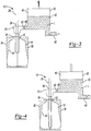
- FIGS. 1-7 show one exemplary sequence according to the present teachings.
- the mold station 10 and associated method utilize a final liquid commodity L to impart the pressure required to expand a hot preform 12 to take on the shape of a mold thus simultaneously forming and filling a resultant container C ( FIG. 7 ).
- the mold station 10 generally includes a mold cavity 16, a pressure source 20, a blow nozzle 22 and a stretch rod 26.
- the exemplary mold cavity 16 illustrated includes mold halves 30, 32 that cooperate to define an interior surface 34 corresponding to a desired outer profile of a blown container.
- the mold cavity 16 may be moveable from an open position ( FIG. 1 ) to a closed position ( FIG. 2 ) such that a support ring 38 of the preform 12 is captured at an upper end of the mold cavity 16.
- the preform 12 may be formed of a polyester material, such as polyethylene terephthalate (PET), having a shape well known to those skilled in the art similar to a test-tube with a generally cylindrical cross section and a length typically approximately fifty percent (50%) that of the resultant container C height.
- PET polyethylene terephthalate
- the support ring 38 may be used to carry or orient the preform 12 through and at various stages of manufacture.
- the preform 12 may be carried by the support ring 38, the support ring 38 may be used to aid in positioning the preform 12 in the mold cavity 16, or an end consumer may use the support ring 38 to carry the plastic container C once manufactured.
- the pressure source 20 can be in the form of, but not limited to, a filling cylinder, manifold or chamber 42 that generally includes a mechanical piston-like device 40 including, but not limited to, a piston, a pump (such as a hydraulic pump) or any other such similarly suitable device, moveable within the filling cylinder, manifold or chamber 42.
- the pressure source 20 has an inlet 46 for accepting the liquid commodity L and an outlet 48 for delivering the liquid commodity L to the blow nozzle 22. It is appreciated that the inlet 46 and the outlet 48 may have valves incorporated thereat.
- the piston-like device 40 may be moveable in a first direction (upward as viewed in the FIGS.) to draw the liquid commodity L from the inlet 46 into the filling cylinder, manifold or chamber 42, and in a second direction (downward as viewed in the FIGS.) to deliver the liquid commodity L from the filling cylinder, manifold or chamber 42 to the blow nozzle 22.
- the piston-like device 40 can be moveable by any suitable method such as pneumatically, mechanically or hydraulically for example.
- the inlet 46 of the pressure source 20 may be connected, such as by tubing or piping to a reservoir or container (not shown) which contains the final liquid commodity L. It is appreciated that the pressure source 20 may be configured differently.
- the blow nozzle 22 generally defines an inlet 50 for accepting the liquid commodity L from the outlet 48 of the pressure source 20 and an outlet 56 ( FIG. 1 ) for delivering the liquid commodity L into the preform 12. It is appreciated that the outlet 56 may define a shape complementary to the preform 12 near the support ring 38 such that the blow nozzle 22 may easily mate with the preform 12 during the forming/filling process. In one example, the blow nozzle 22 may define an opening 58 for slidably accepting the stretch rod 26 used to initiate mechanical stretching of the preform 12.
- the liquid commodity L may be introduced into the plastic container C during a thermal process, typically a hot-fill process.
- bottlers generally fill the plastic container C with a liquid or product at an elevated temperature between approximately 185°F to 205°F (approximately 85°C to 96°C) and seal the plastic container C with a closure (not illustrated) before cooling.
- the liquid may be continuously circulated within the filling cylinder, manifold or chamber 42 through the inlet 46 whereby the liquid can be heated to a preset temperature (i.e., at a heat source (not illustrated) upstream of the inlet 46).
- the plastic container C may be suitable for other high-temperature pasteurization or retort filling processes, or other thermal processes as well.
- the liquid commodity L may be introduced into the plastic container C under ambient or cold temperatures.
- the plastic container C may be filled at ambient or cold temperatures such as between approximately 32°F to 90°F (approximately 0°C to 32°C), and more preferably at approximately 40°F (approximately 4.4°C).
- the preform may be subjected to a sterilization process before introducing the liquid commodity as will be described herein.
- steam S may be directed onto and/or into the preform 12 to partially or completely sterilize the preform 12.
- a sterilizing technique such as steam S
- an aseptic preform and resulting container can be created without requiring the end liquid to be the sterilizing medium. Therefore, the container need not be formed by a hot-filling process.
- the sterilizing medium may be a liquid such as, but not limited to, liquid peroxide.
- the preform 12 may be placed into the mold cavity 16 ( FIG. 2 ).
- a machine places the preform 12 heated to a temperature between approximately 190°F to 250°F (approximately 88°C to 121°C) into the mold cavity 16.
- the piston-like device 40 of the pressure source 20 may begin to draw the .liquid commodity L into the filling cylinder, manifold or chamber 42 through the inlet 46.
- the mold halves 30, 32 of the mold cavity 16 may then close thereby capturing the preform 12 ( FIG. 2 ).
- the blow nozzle 22 may form a seal at a finish of the preform 12.
- the mold cavity 16 may be heated to a temperature between approximately 250°F to 350°F (approximately 93°C to 177°C) in order to impart increased crystallinity levels within the resultant container C.
- the mold cavity 16 may be provided at ambient or cold temperatures between approximately 32°F to 90°F (approximately 0°C to 32°C).
- the liquid commodity L may continue to be drawn into the filling cylinder, manifold or chamber 42 by the piston-like device 40.
- the stretch rod 26 may extend into the preform 12 to initiate mechanical stretching.
- the liquid commodity L may continue to be drawn into the filling cylinder, manifold or chamber 42.
- the stretch rod 26 continues to stretch the preform 12 thereby thinning the sidewalls of the preform 12.
- the volume of the liquid commodity L in the filling cylinder, manifold or chamber 42 may increase until an appropriate volume suitable to form and fill the resultant container C is reached.
- a valve disposed at the inlet 46 of the pressure source 20 may be closed.
- the piston-like device 40 may then begin to drive downward (drive phase) to initiate the rapid transfer of the liquid commodity L from the filling cylinder, manifold or chamber 42 to the preform 12.
- the piston-like device 40 may be actuated by any suitable means such as pneumatic, mechanical and/or hydraulic pressure.
- the hydraulic pressure within the preform 12 may reach between approximately 100 PSI to 600 PSI (6.9 bar to 41.4 bar).
- the liquid commodity L causes the preform 12 to expand toward the interior surface 34 of the mold cavity 16. Residual air may be vented through a passage 70 defined in the stretch rod 26 ( FIG. 5 ). As shown in FIG.
- the piston-like device 40 has completed its drive phase thereby completely transferring the appropriate volume of the liquid commodity L to the newly formed plastic container C.
- the stretch rod 26 may be withdrawn from the mold cavity 16 while continuing to vent residual air.
- the stretch rod 26 may be designed to displace a predetermined volume of the liquid commodity L when it is withdrawn from the mold cavity 16 thereby allowing for the desired fill level of the liquid commodity L within the resultant plastic container C.
- the desired fill level will correspond at or near the level of the support ring 38 of the plastic container C.
- the liquid commodity L can be provided at a constant pressure or at different pressures during the molding cycle.
- the liquid commodity L may be provided at a pressure which is less than the pressure applied when the preform 12 is blown into substantial conformity with the interior surface 34 of the mold cavity 16 defining the final configuration of the plastic container C.
- This lower pressure P 1 may be ambient or greater than ambient but less than a subsequent high pressure P 2 .
- the preform 12 is axially stretched in the mold cavity 16 to a length approximating the final length of the resultant plastic container C. During or just after stretching the preform 12, the preform 12 is generally expanded radially outward under the low pressure P 1 .
- This low pressure P 1 is preferably in the range of between approximately 100 PSI to 150 PSI (6.9 bar to 10.3 bar).
- the preform 12 is further expanded under the high pressure P 2 such that the preform 12 contacts the interior surface 34 of the mold halves 30, 32 thereby forming the resultant plastic container C.
- the high pressure P 2 is in the range of approximately 500 PSI to 600 PSI (34.4 bar to 41.4 bar).
- more than one piston-like device may be employed during the formation of the resultant plastic container C.
- a primary piston-like device may be used to generate the low pressure P 1 to initially expand the preform 12 while a secondary piston-like device may be used to generate the subsequent high pressure P 2 to further expand the preform 12 such that the preform 12 contacts the interior surface 34 of the mold halves 30, 32 thereby forming the resultant plastic container C.
- the fill cycle is shown completed.
- the mold halves 30, 32 may separate and the blow nozzle 22 may be withdrawn.
- the resultant filled plastic container C is now ready for post-forming steps such as capping, labeling and packing.
- the piston-like device 40 may begin the next cycle by drawing the liquid commodity L through the inlet 46 of the pressure source 20 in preparation for the next fill/form cycle.
- the mold station 10 may include a controller for communicating signals to the various components. In this way, components such as, but not limited to, the mold cavity 16, the blow nozzle 22, the stretch rod 26, the piston-like device 40 and various valves may operate according to a signal communicated by the controller. It is also contemplated that the controller may be utilized to adjust various parameters associated with these components according to a given application.
- some of the processing parameters can be lowered while still reaching desired results.
- the requirements for preform conditioning can be reduced because the crystallinity requirements can be lowered.
- mold conditioning requirements can be reduced which can reduce the amount of oils and/or other surface preparation materials used on the interior surface 34 of the mold cavity 16.
- the integrated blowing and filling process described herein can be used to form containers having carbonated beverages (i.e., soda, etc.).
- liquid carbon dioxide can be used in solution as part of, or in addition to, the liquid commodity during the simultaneous blowing and filling process.
- Liquid carbon dioxide prevents foaming that could otherwise occur when blowing with a liquid commodity having gaseous carbon dioxide.
- Carbon dioxide may exist in liquid form at a given pressure and temperature.
- the combination of both the blow and filling processes into one piece of equipment may reduce handling parts and therefore lead to reduced capital cost per resultant plastic container C.
- the space required by a process that simultaneously blows and fills the resultant plastic container C may be significantly reduced over the space required when the processes are separate. This may also result in lower infrastructure cost.
- Integrating the two processes into a single step may reduce labor and additional costs (both capital and expense) associated with handling bottles after they are produced and before they are filled.
- Compressed air is a notoriously inefficient means of transferring energy.
- Using the final product to provide hydraulic pressure to blow the container will require the equivalent of a positive displacement pump. As a result, it is a much more efficient way to transfer energy.
- the preforms may be passed through an oven in excess of 212°F (100°C) and immediately filled and capped. In this way, the opportunity for an empty container to be exposed to the environment where it might become contaminated is greatly reduced. As a result, the cost and complexity of aseptic filling may be greatly reduced.
- the package In some instances where products are hot filled, the package must be designed to accommodate the elevated temperature that it is exposed to during filling and the resultant internal vacuum it is exposed to as a result of the product cooling. A design that accommodates such conditions may require added container weight. Liquid/hydraulic blow molding offers the potential of eliminating the hot fill process and as a result, lowering the package weight.
- the process described herein may eliminate intermediary work in process and therefore may avoid the cost associated with warehousing and/or container silos and/or forklifts and/or product damage, etc. In addition, without work in process inventory, the overall working capital may be reduced.
- blowing and filling are integrated closer but remain as two separate processes (such as conventional methods of forming and subsequently filling)
- the overall efficiency of such a system is the product of the individual efficiencies of the two parts.
- the individual efficiencies may be driven largely by the number of transitions as parts move through the machines. Integrating the two processes into one may provide the opportunity to minimize the number of transitions and therefore increase the overall process efficiency.
- the path that the oxygen has to travel to contact and react with the active scavenging material is much shorter.
- Significant consumption of oxygen scavengers may begin as soon as the container is blown. If the container is formed and filled at the same time, then the scavenger is protecting the product through its entire useful life and not being consumed while the container sits empty waiting to be filled.
- the method described herein may be particularly useful for filling applications such as isotonic, juice, tea and other commodities that are susceptible to biological contamination.
- an aseptic preform and resulting container can be created without requiring the end liquid to be the sterilizing medium.
- These commodities are typically filled in a controlled, sterile environment.
- two ways are typically used to achieve the required sterile environment.
- one primary method for filling these types of beverages is in an aseptic filling environment. The filling operation is performed in a clean room. All of the components of the product including the packaging must be sterilized prior to filling. Once filled, the product may be sealed until it is consumed preventing any potential for the introduction of bacteria. The process is expensive to install and operate. As well as, there is always the risk of a bacterial contaminant breaking through the operational defenses and contaminating the product.
- the concurrent blowing and filling process described herein can also facilitate the formation of a super-lightweight container.
- the container usually needed to have a suitable wall thickness to accommodate vacuum pressures.
- the resultant wall thickness can be much thinner relative to a traditional hot-filled container.
- the liquid itself can give structural support to the container.
- the walls of a super-lightweight container can therefore be extremely flexible.
- liquid commodity L used herein can also include non-consumable goods such as household cleaners, detergents, personal care items such as toothpaste, etc. Many of these products are currently found in blow molded PET containers but are also in extrusion molded plastic containers, glass bottles and/or cans. This technology has the potential of dramatically changing the economics of package manufacture and filling.
- PET containers While much of the description has focused on the production of PET containers, it is contemplated that other polyolefin materials (e.g., polyethylene, polypropylene, polyester, etc.) as well as a number of other plastics may be processed using the teachings discussed herein.
- polyolefin materials e.g., polyethylene, polypropylene, polyester, etc.
Description
- This disclosure generally relates to an apparatus and method for forming and filling a plastic container. More specifically, this disclosure relates to an apparatus and method for simultaneously forming and filling a plastic container.
- As a result of environmental and other concerns, plastic containers, more specifically polyester and even more specifically polyethylene terephthalate (PET) containers are now being used more than ever to package numerous commodities previously supplied in glass containers. Manufacturers and fillers, as well as consumers, have recognized that PET containers are lightweight, inexpensive, recyclable and manufacturable in large quantities.
- Blow-molded plastic containers have become commonplace in packaging numerous commodities. PET is a crystallizable polymer, meaning that it is available in an amorphous form or a semi-crystalline form. The ability of a PET container to maintain its material integrity relates to the percentage of the PET container in crystalline form, also known as the "crystallinity" of the PET container.
- The following equation defines the percentage of crystallinity as a volume fraction:

- Traditionally blow molding and filling have developed as two independent processes, in many cases operated by different companies. In order to make bottle filling more cost effective, some fillers have moved blow molding in house, in many cases integrating blow molders directly into their filling lines. The equipment manufacturers have recognized this advantage and are selling "integrated" systems that are designed to insure that the blow molder and the filler are fully synchronized.
- "
US patent application 2001/010145 discloses an aseptic process and aseptic system for forming and filling a sterilized container from a preform. The preform is first sterilized in a sterilizing unit, and is then transported into a forming unit wherein the preform is stretch-blow moulded in a mould cavity by using a pressurized aseptic gas, in order to form a sterilized container. Said sterilized container is then transported to a filling unit wherein the container is filled with the final product and is capped under aseptic conditions. The forming and filling line, including the blow moulding unit and the filling unit, is enclosed in an aseptic chamber. - The present invention is defined by the system of claim 1 and by the method of
claim 20. - Additional benefits and advantages of the present disclosure will become apparent to those skilled in the art to which the present disclosure relates from the subsequent description and the appended claims, taken in conjunction with the accompanying drawings.
-
-
FIG. 1 is a schematic depiction of a heated preform passed into a mold station and being subject to an optional sterilization step, wherein a pressure source including a piston-like device begins to move upward, drawing liquid into the pressure source in accordance with the teachings of the present disclosure. -
FIG. 2 is a schematic depiction of the system illustrated inFIG. 1 wherein the mold halves close around the preform and liquid continues to accumulate in the pressure source. -
FIG. 3 is a schematic depiction of the system illustrated inFIG. 2 wherein a stretch rod extends into the preform to initiate mechanical stretching and wherein fluid continues to accumulate in the pressure source. -
FIG. 4 is a schematic depiction of the system ofFIG. 3 wherein the stretch rod stretches the preform and wherein fluid has been fully accumulated in the pressure source. -
FIG. 5 is a schematic depiction of the system ofFIG. 4 wherein the piston-like device drives the liquid from the pressure source to the preform thereby expanding the preform toward the walls of the mold cavity. -
FIG. 6 is a schematic depiction of the system ofFIG. 5 wherein the piston-like device has been fully actuated thereby completely transferring an appropriate volume of liquid to the newly formed container and wherein the stretch rod is withdrawing; and -
FIG. 7 is a schematic depiction of the system ofFIG. 6 wherein the mold halves separate and the piston-like device begins to draw liquid into the pressure source in preparation for the next cycle. - The following description is merely exemplary in nature, and is in no way intended to limit the disclosure or its application or uses.
- With reference to all Figures, a mold station according to the present teachings is shown and generally referred to as
reference numeral 10.FIGS. 1-7 show one exemplary sequence according to the present teachings. As will become appreciated from the following description, themold station 10 and associated method utilize a final liquid commodity L to impart the pressure required to expand ahot preform 12 to take on the shape of a mold thus simultaneously forming and filling a resultant container C (FIG. 7 ). - With initial reference to
FIGS. 1 and 2 , themold station 10 will be described in greater detail. Themold station 10 generally includes amold cavity 16, apressure source 20, ablow nozzle 22 and astretch rod 26. Theexemplary mold cavity 16 illustrated includesmold halves interior surface 34 corresponding to a desired outer profile of a blown container. Themold cavity 16 may be moveable from an open position (FIG. 1 ) to a closed position (FIG. 2 ) such that asupport ring 38 of thepreform 12 is captured at an upper end of themold cavity 16. Thepreform 12 may be formed of a polyester material, such as polyethylene terephthalate (PET), having a shape well known to those skilled in the art similar to a test-tube with a generally cylindrical cross section and a length typically approximately fifty percent (50%) that of the resultant container C height. Thesupport ring 38 may be used to carry or orient thepreform 12 through and at various stages of manufacture. For example, thepreform 12 may be carried by thesupport ring 38, thesupport ring 38 may be used to aid in positioning thepreform 12 in themold cavity 16, or an end consumer may use thesupport ring 38 to carry the plastic container C once manufactured. - In one example, the
pressure source 20 can be in the form of, but not limited to, a filling cylinder, manifold orchamber 42 that generally includes a mechanical piston-like device 40 including, but not limited to, a piston, a pump (such as a hydraulic pump) or any other such similarly suitable device, moveable within the filling cylinder, manifold orchamber 42. Thepressure source 20 has aninlet 46 for accepting the liquid commodity L and anoutlet 48 for delivering the liquid commodity L to theblow nozzle 22. It is appreciated that theinlet 46 and theoutlet 48 may have valves incorporated thereat. The piston-like device 40 may be moveable in a first direction (upward as viewed in the FIGS.) to draw the liquid commodity L from theinlet 46 into the filling cylinder, manifold orchamber 42, and in a second direction (downward as viewed in the FIGS.) to deliver the liquid commodity L from the filling cylinder, manifold orchamber 42 to theblow nozzle 22. The piston-like device 40 can be moveable by any suitable method such as pneumatically, mechanically or hydraulically for example. Theinlet 46 of thepressure source 20 may be connected, such as by tubing or piping to a reservoir or container (not shown) which contains the final liquid commodity L. It is appreciated that thepressure source 20 may be configured differently. - The
blow nozzle 22 generally defines aninlet 50 for accepting the liquid commodity L from theoutlet 48 of thepressure source 20 and an outlet 56 (FIG. 1 ) for delivering the liquid commodity L into thepreform 12. It is appreciated that theoutlet 56 may define a shape complementary to thepreform 12 near thesupport ring 38 such that theblow nozzle 22 may easily mate with thepreform 12 during the forming/filling process. In one example, theblow nozzle 22 may define anopening 58 for slidably accepting thestretch rod 26 used to initiate mechanical stretching of thepreform 12. - In one example, the liquid commodity L may be introduced into the plastic container C during a thermal process, typically a hot-fill process. For hot-fill bottling applications, bottlers generally fill the plastic container C with a liquid or product at an elevated temperature between approximately 185°F to 205°F (approximately 85°C to 96°C) and seal the plastic container C with a closure (not illustrated) before cooling. In one configuration, the liquid may be continuously circulated within the filling cylinder, manifold or
chamber 42 through theinlet 46 whereby the liquid can be heated to a preset temperature (i.e., at a heat source (not illustrated) upstream of the inlet 46). In addition, the plastic container C may be suitable for other high-temperature pasteurization or retort filling processes, or other thermal processes as well. In another example, the liquid commodity L may be introduced into the plastic container C under ambient or cold temperatures. Accordingly, by way of example, the plastic container C may be filled at ambient or cold temperatures such as between approximately 32°F to 90°F (approximately 0°C to 32°C), and more preferably at approximately 40°F (approximately 4.4°C). In examples where the liquid commodity is filled at ambient or cold temperatures, the preform may be subjected to a sterilization process before introducing the liquid commodity as will be described herein. - With reference now to all Figures, an exemplary method of simultaneously forming and filling the plastic container C will be described. According to one example (
FIG. 1 ), steam S may be directed onto and/or into thepreform 12 to partially or completely sterilize thepreform 12. By subjecting thepreform 12 to a sterilizing technique (such as steam S), an aseptic preform and resulting container can be created without requiring the end liquid to be the sterilizing medium. Therefore, the container need not be formed by a hot-filling process. It is appreciated that while steam S is shown inFIG. 1 , other sterilizing mediums and/or techniques may be employed. In one example, the sterilizing medium may be a liquid such as, but not limited to, liquid peroxide. - The
preform 12 may be placed into the mold cavity 16 (FIG. 2 ). In one example, a machine (not illustrated) places thepreform 12 heated to a temperature between approximately 190°F to 250°F (approximately 88°C to 121°C) into themold cavity 16. As thepreform 12 is located into themold cavity 16, the piston-like device 40 of thepressure source 20 may begin to draw the .liquid commodity L into the filling cylinder, manifold orchamber 42 through theinlet 46. The mold halves 30, 32 of themold cavity 16 may then close thereby capturing the preform 12 (FIG. 2 ). Theblow nozzle 22 may form a seal at a finish of thepreform 12. Themold cavity 16 may be heated to a temperature between approximately 250°F to 350°F (approximately 93°C to 177°C) in order to impart increased crystallinity levels within the resultant container C. In another example, themold cavity 16 may be provided at ambient or cold temperatures between approximately 32°F to 90°F (approximately 0°C to 32°C). The liquid commodity L may continue to be drawn into the filling cylinder, manifold orchamber 42 by the piston-like device 40. - Turning now to
FIG. 3 , thestretch rod 26 may extend into thepreform 12 to initiate mechanical stretching. At this point, the liquid commodity L may continue to be drawn into the filling cylinder, manifold orchamber 42. With reference toFIG. 4 , thestretch rod 26 continues to stretch thepreform 12 thereby thinning the sidewalls of thepreform 12. The volume of the liquid commodity L in the filling cylinder, manifold orchamber 42 may increase until an appropriate volume suitable to form and fill the resultant container C is reached. At this point, a valve disposed at theinlet 46 of thepressure source 20 may be closed. - With specific reference to
FIG. 5 , the piston-like device 40 may then begin to drive downward (drive phase) to initiate the rapid transfer of the liquid commodity L from the filling cylinder, manifold orchamber 42 to thepreform 12. Again, the piston-like device 40 may be actuated by any suitable means such as pneumatic, mechanical and/or hydraulic pressure. In one example, the hydraulic pressure within thepreform 12 may reach between approximately 100 PSI to 600 PSI (6.9 bar to 41.4 bar). The liquid commodity L causes thepreform 12 to expand toward theinterior surface 34 of themold cavity 16. Residual air may be vented through apassage 70 defined in the stretch rod 26 (FIG. 5 ). As shown inFIG. 6 , the piston-like device 40 has completed its drive phase thereby completely transferring the appropriate volume of the liquid commodity L to the newly formed plastic container C. Next, thestretch rod 26 may be withdrawn from themold cavity 16 while continuing to vent residual air. Thestretch rod 26 may be designed to displace a predetermined volume of the liquid commodity L when it is withdrawn from themold cavity 16 thereby allowing for the desired fill level of the liquid commodity L within the resultant plastic container C. Generally, the desired fill level will correspond at or near the level of thesupport ring 38 of the plastic container C. - Alternatively, the liquid commodity L can be provided at a constant pressure or at different pressures during the molding cycle. For example, during axial stretching of the
preform 12, the liquid commodity L may be provided at a pressure which is less than the pressure applied when thepreform 12 is blown into substantial conformity with theinterior surface 34 of themold cavity 16 defining the final configuration of the plastic container C. This lower pressure P1 may be ambient or greater than ambient but less than a subsequent high pressure P2. Thepreform 12 is axially stretched in themold cavity 16 to a length approximating the final length of the resultant plastic container C. During or just after stretching thepreform 12, thepreform 12 is generally expanded radially outward under the low pressure P1. This low pressure P1 is preferably in the range of between approximately 100 PSI to 150 PSI (6.9 bar to 10.3 bar). Subsequently, thepreform 12 is further expanded under the high pressure P2 such that thepreform 12 contacts theinterior surface 34 of the mold halves 30, 32 thereby forming the resultant plastic container C. Preferably, the high pressure P2 is in the range of approximately 500 PSI to 600 PSI (34.4 bar to 41.4 bar). As a result of the above method, the base and contact ring of the resultant plastic container C is fully circumferentially formed. - Optionally, more than one piston-like device may be employed during the formation of the resultant plastic container C. For example, a primary piston-like device may be used to generate the low pressure P1 to initially expand the
preform 12 while a secondary piston-like device may be used to generate the subsequent high pressure P2 to further expand thepreform 12 such that thepreform 12 contacts theinterior surface 34 of the mold halves 30, 32 thereby forming the resultant plastic container C. - With reference to
FIG. 7 , the fill cycle is shown completed. The mold halves 30, 32 may separate and theblow nozzle 22 may be withdrawn. The resultant filled plastic container C is now ready for post-forming steps such as capping, labeling and packing. At this point, the piston-like device 40 may begin the next cycle by drawing the liquid commodity L through theinlet 46 of thepressure source 20 in preparation for the next fill/form cycle. While not specifically shown, it is appreciated that themold station 10 may include a controller for communicating signals to the various components. In this way, components such as, but not limited to, themold cavity 16, theblow nozzle 22, thestretch rod 26, the piston-like device 40 and various valves may operate according to a signal communicated by the controller. It is also contemplated that the controller may be utilized to adjust various parameters associated with these components according to a given application. - Some additional advantages realized by the present teachings will now be discussed further.
- According to one advantage, some of the processing parameters can be lowered while still reaching desired results. For example, the requirements for preform conditioning can be reduced because the crystallinity requirements can be lowered. In addition, mold conditioning requirements can be reduced which can reduce the amount of oils and/or other surface preparation materials used on the
interior surface 34 of themold cavity 16. - According to one example, the integrated blowing and filling process described herein can be used to form containers having carbonated beverages (i.e., soda, etc.). In such an example, liquid carbon dioxide can be used in solution as part of, or in addition to, the liquid commodity during the simultaneous blowing and filling process. Liquid carbon dioxide prevents foaming that could otherwise occur when blowing with a liquid commodity having gaseous carbon dioxide. Carbon dioxide may exist in liquid form at a given pressure and temperature.
- The combination of both the blow and filling processes into one piece of equipment (mold station 10) may reduce handling parts and therefore lead to reduced capital cost per resultant plastic container C. In addition, the space required by a process that simultaneously blows and fills the resultant plastic container C may be significantly reduced over the space required when the processes are separate. This may also result in lower infrastructure cost.
- Integrating the two processes into a single step may reduce labor and additional costs (both capital and expense) associated with handling bottles after they are produced and before they are filled.
- Integrating the blowing and filling processes into a single process eliminates the need to ship bottles. The shipping of bottles is inherently inefficient and expensive. Shipping preforms, on the other hand, is much more efficient. In one example, a trailer load of empty 500 ml water bottles contains approximately 100,000 individual bottles. The same size trailer loaded with preforms required to make 500 ml water bottles will carry approximately 1,000,000 individual preforms, a 10:1 improvement.
- Compressed air is a notoriously inefficient means of transferring energy. Using the final product to provide hydraulic pressure to blow the container will require the equivalent of a positive displacement pump. As a result, it is a much more efficient way to transfer energy.
- In the exemplary method described herein, the preforms may be passed through an oven in excess of 212°F (100°C) and immediately filled and capped. In this way, the opportunity for an empty container to be exposed to the environment where it might become contaminated is greatly reduced. As a result, the cost and complexity of aseptic filling may be greatly reduced.
- In some instances where products are hot filled, the package must be designed to accommodate the elevated temperature that it is exposed to during filling and the resultant internal vacuum it is exposed to as a result of the product cooling. A design that accommodates such conditions may require added container weight. Liquid/hydraulic blow molding offers the potential of eliminating the hot fill process and as a result, lowering the package weight.
- The process described herein may eliminate intermediary work in process and therefore may avoid the cost associated with warehousing and/or container silos and/or forklifts and/or product damage, etc. In addition, without work in process inventory, the overall working capital may be reduced.
- As blowing and filling are integrated closer but remain as two separate processes (such as conventional methods of forming and subsequently filling), the overall efficiency of such a system is the product of the individual efficiencies of the two parts. The individual efficiencies may be driven largely by the number of transitions as parts move through the machines. Integrating the two processes into one may provide the opportunity to minimize the number of transitions and therefore increase the overall process efficiency.
- Many beverages, including juices, teas, beer, etc., are sensitive to oxygen and need to be protected when packaged. Many plastics do not have sufficient barrier characteristics to protect the contents from oxygen during the life of the packaged product. There are a number of techniques used to impart additional barrier properties to the container to slow down oxygen transmission and therefore protect the packaged contents. One of the most common techniques is to use an oxygen scavenger in the container wall. Such a scavenger may be molded directly into the preform. The relatively thick wall of the preform protects the scavenger from being consumed prior to blowing it into a container. However, once the container has been blown, the surface area of the wall increases and the thickness decreases. As such, the path that the oxygen has to travel to contact and react with the active scavenging material is much shorter. Significant consumption of oxygen scavengers may begin as soon as the container is blown. If the container is formed and filled at the same time, then the scavenger is protecting the product through its entire useful life and not being consumed while the container sits empty waiting to be filled.
- The method described herein may be particularly useful for filling applications such as isotonic, juice, tea and other commodities that are susceptible to biological contamination. In particular, by optionally sterilizing the preform as described above, an aseptic preform and resulting container can be created without requiring the end liquid to be the sterilizing medium. These commodities are typically filled in a controlled, sterile environment. Commercially, two ways are typically used to achieve the required sterile environment. In Europe, one primary method for filling these types of beverages is in an aseptic filling environment. The filling operation is performed in a clean room. All of the components of the product including the packaging must be sterilized prior to filling. Once filled, the product may be sealed until it is consumed preventing any potential for the introduction of bacteria. The process is expensive to install and operate. As well as, there is always the risk of a bacterial contaminant breaking through the operational defenses and contaminating the product.
- In North America, one predominant method for filling contaminant susceptible beverages is through hot filling. In this process, the beverage is introduced to the container at a temperature that will kill any bacteria that is present. The container may be sealed while the product is hot. One drawback to this technology is that the containers usually need to be heavy to sustain the elevated filling temperature and the vacuum that eventually develops in the container as the product cools. As well as, the blow process is somewhat more complex and therefore more costly than non-heat set blow molding. The disclosure described herein offers the opportunity to dramatically reduce the cost and complexity of filling sensitive foods and beverages. By combining the blowing and filling processes, there is an ability to heat the preform to over 212°F (100°C) for a sufficient period of time necessary to kill any biological contaminants. If a sterile product is used as the container-forming medium and then immediately sealed, the process may result in a very inexpensive aseptic filling process with very little opportunity for contamination.
- The concurrent blowing and filling process described herein can also facilitate the formation of a super-lightweight container. As noted above, in traditional hot-fill containers, the container usually needed to have a suitable wall thickness to accommodate vacuum pressures. By sterilizing the preform 12 (i.e. such as by subjecting it to steam S,
FIG. 1 ) prior to introducing the liquid commodity, the resultant wall thickness can be much thinner relative to a traditional hot-filled container. In a super-lightweight container, the liquid itself can give structural support to the container. The walls of a super-lightweight container can therefore be extremely flexible. - There are many other bottled products where this technology may be applicable. Consumable products such as dairy products, liquor, salad dressings, sauces, spreads, ketchups, syrups, edible oils, and others may be bottled utilizing such methods. Furthermore, the term liquid commodity L used herein can also include non-consumable goods such as household cleaners, detergents, personal care items such as toothpaste, etc. Many of these products are currently found in blow molded PET containers but are also in extrusion molded plastic containers, glass bottles and/or cans. This technology has the potential of dramatically changing the economics of package manufacture and filling.
- While much of the description has focused on the production of PET containers, it is contemplated that other polyolefin materials (e.g., polyethylene, polypropylene, polyester, etc.) as well as a number of other plastics may be processed using the teachings discussed herein.
Claims (32)
- A system for simultaneously forming and filling a container (C) comprising:a mold cavity (16) defining an internal surface (34) and adapted to accept a preform (12);a sterilizing apparatus that sterilizes the preform;a pressure source (20) having an inlet (46), a chamber (42) and a piston-like device (40) moveable within the chamber in a first direction wherein liquid is drawn into the chamber through the inlet and in a second direction wherein the liquid is urged toward the preform; anda blow nozzle (22) adapted to receive the liquid from the pressure source and transfer the liquid at a pressure into the preform thereby urging the preform to expand toward the internal surface of the mold cavity and create a resultant container, wherein the liquid remains within the container as an end product.
- The system for simultaneously forming and filling a container according to Claim 1 wherein the piston-like device is one of a piston, and a pump and an accumulator.
- The system for simultaneously forming and filling a container according to anyone of Claims 1 to 2 wherein the blow nozzle defines a shape adapted to form a seal with a finish of the preform.
- The system for simultaneously forming and filling a container according to anyone of Claims 1 to 3 wherein the liquid is transferred into the preform during a hot- fill process.
- The system for simultaneously forming and filling a container according to Claim 4 wherein the liquid is transferred into the preform at a temperature between approximately 85°C (185°F) and approximately 96°C (205°F).
- The system for simultaneously forming and filling a container according to anyone of Claim 1 to 3 wherein the liquid is transferred into the preform at an ambient temperature.
- The system for simultaneously forming and filling a container according to Claim 6 wherein the liquid is transferred into the preform at a temperature between approximately 0°C (32°F) and 32°C (90°F).
- The system for simultaneously forming and filling a container according to Claims 1 and 7 wherein the sterilizing apparatus emits steam onto and/or into the preform.
- The system for simultaneously forming and filling a container according to Claims 1 and 7 wherein the sterilizing apparatus emits a sterilizing liquid onto and/or into the preform.
- The system for simultaneously forming and filling a container according to Claim 9 wherein the sterilizing liquid comprises peroxide.
- The system for simultaneously forming and filling a container according to anyone of Claims 1 to 10 wherein the mold cavity accepts a preform heated to a temperature between approximately 88°C (190°F) and approximately 1210°C (250°F).
- The system for simultaneously forming and filling a container according to anyone of Claims 1 to 11 wherein the mold cavity is heated to a temperature between approximately 93°C (250°F) and approximately 177°C (350°F).
- The system for simultaneously forming and filling a container according to anyone of Claims 1 to 12 wherein the liquid is transferred into the preform at a pressure between approximately 6.9 bar (100 PSI) and approximately 41.4 bar (600 PSI).
- The system for simultaneously forming and filling a container according to anyone of Claims 1 to 13, further comprising a stretch rod adapted to extend into the preform and mechanically stretch the preform prior to the liquid being urged into the preform.
- The system for simultaneously forming and filling a container according to Claim 14 wherein the stretch rod is vented to atmosphere.
- The system for simultaneously forming and filling a container according to anyone of Claims 1 to 15 wherein the preform is initially expanded outwardly under a first pressure and subsequently expanded outwardly under a second pressure, the second pressure being greater than the first pressure.
- The system for simultaneously forming and filling a container according to Claim 16 wherein the first pressure is between approximately 6.9 bar (100 PSI) and
- The system for simultaneously forming and filling a container according to approximately 10.3 bar (150 PSI), and the second pressure is between approximately 34.4 bar (500 PSI) and approximately 41.4 bar (600 PSI).
- The system for simultaneously forming and filling a container according to Claim 1 wherein the piston-like device comprises a first piston-like device that generates the first pressure and a second piston-like device that generates the second pressure.
- The system for simultaneously forming and filling a container according to anyone of Claims 1 to 18 wherein the liquid includes a solution comprising in part liquid carbon dioxide.
- A method of simultaneously forming and filling a container (C) comprising:locating a preform (12) in a mold cavity (16) having an internal surface (34);sealably connecting a blow nozzle (22) onto an opening of the preform;accumulating liquid into a chamber (42);sterilizing the preform prior to delivering the liquid into the preform; anddelivering the liquid from the chamber, through the blow nozzle into the opening of the preform thereby urging the preform to expand toward the internal surface of the mold cavity and create a resultant container, wherein the liquid remains within the container as an end product.
- The method of simultaneously forming and filling a container of Claim 20 wherein delivering the liquid from the chamber includes transferring the liquid into the preform at a temperature between approximately 85°C (185°F) and approximately 96°C (205°F).
- The method of simultaneously forming and filling a container of Claim 20, wherein delivering the liquid from the chamber includes transferring the liquid into the preform at an ambient temperature.
- The method of simultaneously forming and filling a container of Claim 20. wherein delivering the liquid from the chamber includes transferring the liquid into the preform at a temperature between approximately 0°C (32°F) and approximately 32°C (90°F).
- The method of simultaneously forming and filing a container of Claim 20 wherein delivering the liquid from the chamber includes transferring the liquid into the preform, wherein the preform is heated to a temperature between approximately 88°C (190°F) and approximately 121°C (250°F).
- The method of simultaneously forming and filling a container of Claim 20 wherein locating the preform in the mold cavity includes locating the preform in a mold cavity that is heated to a temperature between approximately 93°C (250°F) and approximately 177°C (350°F).
- The method of simultaneously forming and filling a container of Claim 20 wherein delivering the liquid from the chamber includes transferring the liquid into the preform at a pressure between approximately 6.9 bar (100 PSI) and approximately 41.4 bar (600 PSI).
- The method of simultaneously forming and filling a container of Claim 20, further comprising advancing a stretch rod into the preform thereby mechanically stretching the preform prior to the liquid being urged into the preform.
- The method of simultaneously forming and filling a container of Claim 27 wherein advancing the stretch rod into the preform includes venting residual air in the preform through a passage defined in the stretch rod.
- The method of simultaneously forming and filling a container of Claim 26 wherein delivering the liquid from the chamber comprises:initially transferring the liquid at a first pressure; andsubsequently transferring the liquid at a second pressure, the second pressure being greater than the first pressure.
- The method of simultaneously forming and filling a container of Claim 29 wherein the first pressure is between approximately 6.9 bar (100 PSI) and approximately 10.3 bar (150 PSI), and the second pressure is between approximately 34.4 bar (500 PSI) and approximately 41.4 bar (600 PSI).
- The method of simultaneously forming and filling a container of Claim 30 wherein the first pressure is generated from a first piston-like device and the second pressure is generated from a second piston-like device.
Applications Claiming Priority (3)
| Application Number | Priority Date | Filing Date | Title |
|---|---|---|---|
| US565507P | 2007-12-06 | 2007-12-06 | |
| US12/328,578 US8017064B2 (en) | 2007-12-06 | 2008-12-04 | Liquid or hydraulic blow molding |
| PCT/US2008/013429 WO2009075791A1 (en) | 2007-12-06 | 2008-12-05 | Liquid or hydraulic blow molding |
Publications (3)
| Publication Number | Publication Date |
|---|---|
| EP2225085A1 EP2225085A1 (en) | 2010-09-08 |
| EP2225085A4 EP2225085A4 (en) | 2012-04-18 |
| EP2225085B1 true EP2225085B1 (en) | 2019-10-30 |
Family
ID=40755779
Family Applications (1)
| Application Number | Title | Priority Date | Filing Date |
|---|---|---|---|
| EP08858876.9A Active EP2225085B1 (en) | 2007-12-06 | 2008-12-05 | Liquid or hydraulic blow molding |
Country Status (6)
| Country | Link |
|---|---|
| US (3) | US8017064B2 (en) |
| EP (1) | EP2225085B1 (en) |
| JP (1) | JP5600297B2 (en) |
| BR (1) | BRPI0821065B1 (en) |
| MX (1) | MX2010006256A (en) |
| WO (1) | WO2009075791A1 (en) |
Families Citing this family (79)
| Publication number | Priority date | Publication date | Assignee | Title |
|---|---|---|---|---|
| US7981356B2 (en) * | 2005-03-15 | 2011-07-19 | Invoplas Pty Ltd | Stretch blow moulding method and apparatus |
| US8573964B2 (en) * | 2006-04-13 | 2013-11-05 | Amcor Limited | Liquid or hydraulic blow molding |
| US7914726B2 (en) * | 2006-04-13 | 2011-03-29 | Amcor Limited | Liquid or hydraulic blow molding |
| FR2922151B1 (en) * | 2007-10-10 | 2010-01-01 | Tecsor | METHOD FOR PRESSURIZING THE INTERIOR OF A THIN-FILM CONTAINER CONTAINING PRESSURIZED PRESSURE |
| US8017064B2 (en) | 2007-12-06 | 2011-09-13 | Amcor Limited | Liquid or hydraulic blow molding |
| EP2143545A1 (en) * | 2008-07-07 | 2010-01-13 | Nestec S.A. | Method and apparatus for packaging a liquid food product |
| DE102010007541A1 (en) | 2009-12-23 | 2011-06-30 | KHS Corpoplast GmbH, 22145 | Method and device for producing filled containers |
| DE102010022132B4 (en) * | 2010-05-20 | 2023-03-16 | Krones Aktiengesellschaft | Device for forming plastic preforms into plastic containers and for supplying a sterilization medium and a method for operating the device |
| FR2962930B1 (en) * | 2010-07-20 | 2012-08-31 | Sidel Participations | PROCESS FOR FORMING A CONTAINER BY BLOWING AND FILLING |
| US8834778B2 (en) * | 2010-09-13 | 2014-09-16 | Amcor Limited | Mold delay for increased pressure for forming container |
| US8828308B2 (en) | 2010-09-13 | 2014-09-09 | Amcor Limited | Hydroblow preform design |
| US8721315B2 (en) | 2010-09-13 | 2014-05-13 | Amcor Limited | Method of handling liquid to prevent machine contamination during filling |
| US8968636B2 (en) * | 2010-10-15 | 2015-03-03 | Discma Ag | Stretch rod system for liquid or hydraulic blow molding |
| US9314955B2 (en) * | 2010-10-15 | 2016-04-19 | Discma Ag | Use of optimized piston member for generating peak liquid pressure |
| US8714964B2 (en) * | 2010-10-15 | 2014-05-06 | Amcor Limited | Blow nozzle to control liquid flow with pre-stretch rod assembly |
| EP2463079A1 (en) * | 2010-12-10 | 2012-06-13 | Nestec S.A. | A process for single-step forming and filling of containers |
| CN103635389B (en) * | 2011-01-31 | 2016-04-13 | Khs有限责任公司 | The method and apparatus of the container of filling for the manufacture of utilizing liquid filler |
| AU2012217945B2 (en) | 2011-02-15 | 2017-05-11 | Discma Ag | Reverse stretch rod for machine hygiene and processing |
| BR112013021068B1 (en) | 2011-02-16 | 2021-09-14 | Amcor Limited | BLOW NOZZLE TO CONTROL LIQUID FLOW WITH PRE-STRETCH STEM ASSEMBLY AND METALLIC SETTING SEALING PIN |
| DE102011012751B4 (en) * | 2011-03-01 | 2014-07-31 | Khs Corpoplast Gmbh | Process and plant for the production of containers filled with a liquid product |
| DE102011102090B4 (en) * | 2011-05-19 | 2018-02-08 | Khs Corpoplast Gmbh | Method for cleaning and / or disinfecting a device for producing containers filled with a liquid product and apparatus |
| US9044887B2 (en) | 2011-05-27 | 2015-06-02 | Discma Ag | Method of forming a container |
| US8740609B2 (en) | 2011-06-09 | 2014-06-03 | Amcor Limited | CSD cooling and pressurization to keep CO2 in solution during forming |
| EP2694271B1 (en) * | 2011-06-09 | 2015-10-21 | Discma AG | System |
| WO2012170621A2 (en) * | 2011-06-09 | 2012-12-13 | Amcor Limited | Method for forming a preform for a container |
| BR112014000484B1 (en) * | 2011-08-08 | 2020-06-30 | Discma Ag. | degassing method of a container filled with carbonated drink |
| US9802375B2 (en) | 2011-10-27 | 2017-10-31 | Discma Ag | Counter stretch connecting rod and positive fill level control rod |
| WO2013063453A1 (en) * | 2011-10-27 | 2013-05-02 | Amcor Limited | Method and apparatus for forming and filling a container |
| WO2013096609A1 (en) * | 2011-12-21 | 2013-06-27 | Amcor Limited | A sealing system for molding machine |
| BR112014015315B1 (en) * | 2011-12-21 | 2021-05-25 | Amcor Limited | preform blow molding system and method of forming and filling a container with an end product |
| EP2607052A1 (en) * | 2011-12-21 | 2013-06-26 | Nestec S.A. | A method and system for blowing and filling lightweight containers |
| EP2794235B1 (en) | 2011-12-22 | 2018-07-18 | Discma AG | Method for controlling temperature gradient through wall thickness of container |
| JP5980576B2 (en) * | 2012-05-30 | 2016-08-31 | 株式会社吉野工業所 | Blow molding equipment |
| JP5765657B2 (en) * | 2012-01-31 | 2015-08-19 | 株式会社吉野工業所 | Blow molding equipment |
| US9180621B2 (en) | 2012-01-31 | 2015-11-10 | Discma Ag | Blow molding device |
| JP6108088B2 (en) * | 2012-03-14 | 2017-04-05 | 大日本印刷株式会社 | Preform sterilization method and contents filling method and apparatus |
| JP6007685B2 (en) * | 2012-09-05 | 2016-10-12 | 大日本印刷株式会社 | Preform sterilization method and contents filling method and apparatus |
| CN104428121B (en) * | 2012-07-10 | 2016-12-14 | 帝斯克玛股份有限公司 | For utilizing the aerated product blowing being in ambient temperature and the method and system filling container |
| DE102012015087A1 (en) * | 2012-08-01 | 2014-05-15 | Khs Corpoplast Gmbh | Method and device for producing filled with a liquid product containers |
| JP5870001B2 (en) | 2012-09-28 | 2016-02-24 | 株式会社吉野工業所 | Blow molding apparatus and container manufacturing method |
| JP5808733B2 (en) * | 2012-12-28 | 2015-11-10 | 株式会社吉野工業所 | Blow molding equipment |
| DE102013101642A1 (en) * | 2013-02-19 | 2014-08-21 | Khs Gmbh | Method and device for producing and filling containers |
| JP6280205B2 (en) * | 2013-03-26 | 2018-02-14 | ディスクマ アクチェンゲゼルシャフト | Hydrophobic mold |
| WO2014173845A1 (en) * | 2013-04-24 | 2014-10-30 | Discma Ag | Method and machine for manufacturing plastic containers |
| EP2801468B1 (en) * | 2013-05-07 | 2018-02-28 | Discma AG | Apparatus and method for fabricating containers |
| EP2801469A1 (en) * | 2013-05-07 | 2014-11-12 | Nestec S.A. | Apparatus and method for fabricating containers |
| WO2014206978A1 (en) * | 2013-06-24 | 2014-12-31 | Discma Ag | Method for forming containers by applying a pressure profile controled by a stretch rod |
| EP3013555B1 (en) | 2013-06-28 | 2018-02-07 | Discma AG | Method of molding a container |
| EP3013557B1 (en) * | 2013-06-28 | 2021-02-17 | Discma AG | Two stage flow through seal pin |
| CN105899605A (en) | 2013-08-30 | 2016-08-24 | 帝斯克玛股份有限公司 | Highly modified polyesters for containers |
| EP2860015B1 (en) * | 2013-10-10 | 2017-12-20 | Discma AG | Method of delivering a liquid volume and associated apparatus |
| EP3202550B1 (en) * | 2014-03-10 | 2018-09-05 | Discma AG | Method of forming and setting headspace within a container |
| EP2987609A1 (en) * | 2014-08-20 | 2016-02-24 | Krones AG | Mould filling machine with cleaning and method |
| WO2016067511A1 (en) * | 2014-10-30 | 2016-05-06 | 株式会社吉野工業所 | Preform for liquid blow moulding |
| WO2016067512A1 (en) * | 2014-10-30 | 2016-05-06 | 株式会社吉野工業所 | Preform for liquid blow moulding |
| JP6553453B2 (en) * | 2014-10-30 | 2019-07-31 | 株式会社吉野工業所 | Liquid blow molding method |
| DE102014016140A1 (en) * | 2014-10-30 | 2016-05-04 | Khs Corpoplast Gmbh | Process for removing air from preforms for producing filled plastic containers |
| JP6511359B2 (en) * | 2014-10-30 | 2019-05-15 | 株式会社吉野工業所 | Container manufacturing method |
| JP6628513B2 (en) * | 2015-07-14 | 2020-01-08 | 株式会社吉野工業所 | Container manufacturing method |
| JP6628512B2 (en) * | 2015-07-14 | 2020-01-08 | 株式会社吉野工業所 | Container manufacturing method |
| WO2017010074A1 (en) * | 2015-07-14 | 2017-01-19 | 株式会社吉野工業所 | Method for producing container |
| EP3205473B1 (en) | 2016-02-11 | 2018-10-24 | Discma AG | Injection device for a forming and filling station adapted for cip |
| JP6619681B2 (en) * | 2016-03-31 | 2019-12-11 | 株式会社吉野工業所 | Blow molding method |
| JP6693822B2 (en) * | 2016-06-30 | 2020-05-13 | 株式会社吉野工業所 | Container manufacturing method by liquid blow molding |
| EP3374148B1 (en) * | 2017-02-03 | 2019-06-26 | KHS Corpoplast GmbH | Method and apparatus for producing liquid-contents-filled containers from preforms by contents being introduced into the preform under pressure |
| BR112019018663B1 (en) * | 2017-04-26 | 2023-05-16 | Amcor Rigid Plastics Usa, Llc | PORTABLE MODULE FOR A CONTAINER FORMING AND FILLING SYSTEM |
| WO2018207787A1 (en) | 2017-05-10 | 2018-11-15 | 大日本印刷株式会社 | Aseptic filling machine and aseptic filling method |
| JP6940807B2 (en) * | 2017-05-17 | 2021-09-29 | 大日本印刷株式会社 | Aseptic filling machine and aseptic filling method |
| JP7428464B2 (en) * | 2017-05-10 | 2024-02-06 | 大日本印刷株式会社 | Aseptic filling machine and aseptic filling method |
| US11198243B2 (en) | 2018-01-11 | 2021-12-14 | Husky Injection Molding Systems Ltd. | Method and apparatus for forming final-shaped containers using liquid to be contained therein |
| WO2019230551A1 (en) * | 2018-05-31 | 2019-12-05 | 日精エー・エス・ビー機械株式会社 | Blow nozzle for use in blow molding device, blow molding method employing said blow nozzle, and stretching rod |
| DE102018115189A1 (en) | 2018-06-25 | 2020-01-02 | Khs Corpoplast Gmbh | Device for producing containers by blow molding |
| CN112272605B (en) | 2018-06-29 | 2023-10-20 | 帝斯克玛股份有限公司 | Method of using liquid extrusion blow molding |
| CN112368125A (en) * | 2018-06-29 | 2021-02-12 | 帝斯克玛股份有限公司 | Blow molding station and method for forming free blow molded containers |
| US20210309840A1 (en) * | 2018-08-21 | 2021-10-07 | Amcor Rigid Packaging Usa, Llc | Polyolefin resins for containers |
| EP3990250A1 (en) | 2019-06-27 | 2022-05-04 | Discma AG | High pressure process of forming and filling a container and corresponding system |
| WO2020261122A1 (en) | 2019-06-28 | 2020-12-30 | Discma Ag | Reduced material container and system and method of forming the same |
| WO2021162701A1 (en) | 2020-02-14 | 2021-08-19 | Amcor Rigid Packaging Usa, Llc | Container preform and forming/filling nozzle each configured to provide a seal therebetween |
| CN115697676A (en) | 2020-06-18 | 2023-02-03 | 帝斯克玛股份有限公司 | Container forming and filling system with hydrophobic properties |
Family Cites Families (81)
| Publication number | Priority date | Publication date | Assignee | Title |
|---|---|---|---|---|
| US3267185A (en) | 1962-12-31 | 1966-08-16 | Union Oil Co | Method and apparatus for forming and filling hollow plastic articles |
| US3268635A (en) | 1963-02-25 | 1966-08-23 | Robert A Kraus | Arrangement for forming foam plastic article |
| DE1779306A1 (en) * | 1968-07-27 | 1971-09-16 | Bosch Gmbh Robert | Device for blow molding hollow bodies from preforms |
| US3993427A (en) | 1974-10-11 | 1976-11-23 | Monsanto Company | Movable preform locator and blow air valve apparatus for a blow molding machine |
| GB1474044A (en) | 1974-12-03 | 1977-05-18 | Ici Ltd | Plastics container manufacture |
| DE2717365A1 (en) | 1977-04-20 | 1978-10-26 | Bekum Maschf Gmbh | METHOD FOR MANUFACTURING HOLLOW BODIES FROM THERMOPLASTIC PLASTIC |
| DE2927617A1 (en) | 1979-07-07 | 1981-01-08 | Cillichemie | DOSING DEVICE |
| JPS57123027A (en) | 1981-01-26 | 1982-07-31 | Pentel Kk | Method of blow molding plastic container filled with paste such as color |
| US4432720A (en) * | 1981-04-24 | 1984-02-21 | Cincinnati Milacron Inc. | Apparatus for high rate production of biaxially oriented thermoplastic articles |
| US4457688A (en) * | 1981-05-07 | 1984-07-03 | Cincinnati Milacron Inc. | External center pin for blow molding machine |
| FR2510940A1 (en) | 1981-08-06 | 1983-02-11 | Solvay | PROCESS AND APPARATUS FOR THE MANUFACTURE OF MOLECULAR ORIENTED PLASTIC PIPES |
| US4490327A (en) * | 1982-02-03 | 1984-12-25 | Cincinnati Milacron Industries, Inc. | External center pin for blow molding machine |
| US4539172A (en) | 1983-12-16 | 1985-09-03 | Baxter Travenol Laboratories, Inc. | Method of blowmolding a container having an integral inner dispensing outlet |
| US4725464A (en) * | 1986-05-30 | 1988-02-16 | Continental Pet Technologies, Inc. | Refillable polyester beverage bottle and preform for forming same |
| US4755404A (en) | 1986-05-30 | 1988-07-05 | Continental Pet Technologies, Inc. | Refillable polyester beverage bottle and preform for forming same |
| US4883631A (en) | 1986-09-22 | 1989-11-28 | Owens-Illinois Plastic Products Inc. | Heat set method for oval containers |
| JPS63249616A (en) | 1987-04-07 | 1988-10-17 | Komatsu Ltd | Method for molding resin |
| US4935190A (en) | 1987-07-10 | 1990-06-19 | William G. Whitney | Method of making balloon retention catheter |
| US4861260A (en) * | 1988-02-19 | 1989-08-29 | Broadway Companies, Inc. | Apparatus for forming a blown plastic container |
| US5352402A (en) * | 1989-10-23 | 1994-10-04 | Nissei Asb Machine Co., Ltd. | Method and apparatus for manufacturing biaxially oriented, thermally stable, blown containers |
| EP0428394B1 (en) | 1989-11-16 | 1996-05-01 | Mitsui Petrochemical Industries, Ltd. | Container with a suspension grip and method of manufacturing the same |
| US5066528A (en) * | 1990-03-05 | 1991-11-19 | Continental Pet Technologies, Inc. | Refillable polyester container and preform for forming the same |
| JPH0675911B2 (en) | 1990-08-14 | 1994-09-28 | 日精エー・エス・ビー機械株式会社 | Method and apparatus for stretch blow molding of wide mouth container |
| JPH0813498B2 (en) * | 1992-02-29 | 1996-02-14 | 日精エー・エス・ビー機械株式会社 | Molding method for heat-resistant container |
| US5344596A (en) * | 1992-03-23 | 1994-09-06 | Icp Systems, Inc. | Method for fluid compression of injection molded plastic material |
| US5269672A (en) * | 1992-06-29 | 1993-12-14 | Hoover Universal, Inc. | Servo stretch assembly for blow molding machine |
| US5474735A (en) | 1993-09-24 | 1995-12-12 | Continental Pet Technologies, Inc. | Pulse blow method for forming container with enhanced thermal stability |
| US5486103A (en) * | 1994-05-09 | 1996-01-23 | Electra Form, Inc. | Blow mold clamp assembly |
| US5635226A (en) * | 1994-09-26 | 1997-06-03 | A.K. Technical Laboratory Inc. | Composite molding device for stretch blow molding |
| DE4439231C1 (en) * | 1994-11-03 | 1996-04-25 | Bernd Hansen | Blow molding process for producing a closed container and container produced according to this process |
| KR0147442B1 (en) | 1994-11-15 | 1998-08-17 | 성재갑 | Injection type mould |
| DE4441815C2 (en) * | 1994-11-24 | 1997-09-18 | Tuhh Tech Gmbh | Method and device for producing plastic parts |
| JP3286099B2 (en) | 1995-01-25 | 2002-05-27 | 東洋機械金属株式会社 | Injection molding machine |
| US6214282B1 (en) | 1995-08-23 | 2001-04-10 | The Japan Steel Works, Ltd. | Simultaneous filling blow molding method and apparatus |
| JPH0999477A (en) | 1995-10-06 | 1997-04-15 | Japan Steel Works Ltd:The | Simultaneous fitting and hollow molding method and apparatus |
| JPH0957834A (en) | 1995-08-23 | 1997-03-04 | Japan Steel Works Ltd:The | Liquid filling method of simultaneous filling and hollow molding machine and device therefor |
| US5962039A (en) | 1997-02-21 | 1999-10-05 | The Japan Steel Works, Ltd. | Simultaneous filling blow molding apparatus |
| JP2984228B2 (en) | 1996-12-05 | 1999-11-29 | 東海ゴム工業株式会社 | Mold for epoxy resin molding |
| US5845667A (en) | 1996-12-19 | 1998-12-08 | Saturn Electronics & Engineering, Inc. | Single stage variable force solenoid pressure regulating valve |
| SE511861C2 (en) | 1998-04-07 | 1999-12-06 | Tetra Laval Holdings & Finance | Method and apparatus for producing a sterile packaging container |
| US6277321B1 (en) | 1998-04-09 | 2001-08-21 | Schmalbach-Lubeca Ag | Method of forming wide-mouth, heat-set, pinch-grip containers |
| JP2000043129A (en) | 1998-07-29 | 2000-02-15 | Ishikawajima Harima Heavy Ind Co Ltd | Molding of plastic container |
| JP2000167915A (en) * | 1998-12-04 | 2000-06-20 | Ishikawajima Harima Heavy Ind Co Ltd | Method and apparatus for molding plastic container |
| DE19929033B4 (en) * | 1999-06-25 | 2009-05-07 | Khs Corpoplast Gmbh & Co. Kg | Device for blow molding containers |
| US6485669B1 (en) | 1999-09-14 | 2002-11-26 | Schmalbach-Lubeca Ag | Blow molding method for producing pasteurizable containers |
| US6485670B1 (en) | 1999-11-09 | 2002-11-26 | Schmalbach-Lubeca Ag | Blow molding method for producing pasteurizable containers |
| KR100742076B1 (en) | 1999-11-30 | 2007-07-23 | 가부시키가이샤 요시노 고교쇼 | Polyester resin lamination vessel and molding method therefor |
| JP2001212874A (en) | 2000-02-02 | 2001-08-07 | Shikoku Kakoki Co Ltd | Method for molding and filling sterile container |
| JP2002067131A (en) | 2000-08-30 | 2002-03-05 | Aoki Technical Laboratory Inc | Stretch blow molding method and blow mold |
| FR2814392B1 (en) | 2000-09-25 | 2002-12-20 | Sidel Sa | STRETCH-BLOWING MACHINE HAVING IMPROVED DRAWING ROD CONTROL |
| US6502369B1 (en) * | 2000-10-25 | 2003-01-07 | Amcor Twinpak-North America Inc. | Method of supporting plastic containers during product filling and packaging when exposed to elevated temperatures and internal pressure variations |
| ITPN20010009A1 (en) * | 2001-02-07 | 2002-08-07 | Sipa Spa | PROCEDURE FOR THE PRODUCTION OF PET CONTAINERS WITH OUT-OF-CENTER MOUTH |
| JP3797156B2 (en) | 2001-08-21 | 2006-07-12 | 東洋製罐株式会社 | Preforms for blow molding of bottle-shaped containers |
| US7141190B2 (en) | 2001-11-27 | 2006-11-28 | Hekal Ihab M | Biaxially oriented hollow thermoplastic bodies and improved method for sterilization |
| FR2839277B1 (en) | 2002-05-03 | 2005-04-08 | Nestle Waters Man & Technology | PROCESS FOR MANUFACTURING A POLYESTER RESIN CONTAINER AND DEVICE FOR IMPLEMENTING IT |
| FR2848906B1 (en) | 2002-12-23 | 2006-08-18 | Sidel Sa | METHOD AND INSTALLATION FOR MANUFACTURING A CONTAINER OF PLASTIC MATERIAL |
| KR101111419B1 (en) | 2003-06-18 | 2012-02-15 | 더 코카콜라 컴파니 | Polyester composition for hot fill applications, containers made therewith, and methods |
| JP4292918B2 (en) | 2003-08-22 | 2009-07-08 | 東洋製罐株式会社 | Preforms for plastic bottle containers |
| US20050098527A1 (en) * | 2003-09-15 | 2005-05-12 | Yates William M.Iii | Multiple cavity bottle and method of manufacturing same |
| US20050067002A1 (en) | 2003-09-25 | 2005-03-31 | Supercritical Systems, Inc. | Processing chamber including a circulation loop integrally formed in a chamber housing |
| DE60326353D1 (en) | 2003-11-06 | 2009-04-09 | Nestle Waters Man & Technology | Production process of polyester resin containers |
| FR2863930B1 (en) | 2003-12-19 | 2006-03-03 | Sidel Sa | MOLDING DEVICE FOR MANUFACTURING CONTAINERS OF THERMOPLASTIC MATERIAL |
| ITMO20040034A1 (en) * | 2004-02-16 | 2004-05-16 | Benco Pack Spa | CONTAINER FORMING |
| JP4335040B2 (en) | 2004-03-15 | 2009-09-30 | 株式会社フロンティア | Blow molding method for plastic containers |
| ITPN20040021A1 (en) | 2004-03-19 | 2004-06-19 | Servizi Tecnici Avanzati S R L | "BOTTLE FILLING SYSTEM WITH PERFECTED FILLING VALVE" |
| EP1688234A3 (en) | 2005-02-04 | 2006-10-11 | The Procter & Gamble Company | A process for forming a container by stretch blow molding and container formed thereby |
| US7981356B2 (en) | 2005-03-15 | 2011-07-19 | Invoplas Pty Ltd | Stretch blow moulding method and apparatus |
| US20060231646A1 (en) * | 2005-04-18 | 2006-10-19 | Geary Charles T Jr | Straight flow nozzle |
| FR2887525B1 (en) * | 2005-06-24 | 2007-09-07 | Sidel Sas | INSTALLATION PRODUCING STERILE BOTTLES BY BLOWING FROM STERILIZED PREFORMS |
| US7621465B2 (en) * | 2005-11-10 | 2009-11-24 | Nordson Corporation | Air annulus cut off nozzle to reduce stringing and method |
| US8573964B2 (en) * | 2006-04-13 | 2013-11-05 | Amcor Limited | Liquid or hydraulic blow molding |
| US7914726B2 (en) | 2006-04-13 | 2011-03-29 | Amcor Limited | Liquid or hydraulic blow molding |
| US20080161465A1 (en) * | 2006-12-28 | 2008-07-03 | Jason Christopher Jenkins | Oxygen-scavenging polyester compositions useful for packaging |
| ITVI20070100A1 (en) | 2007-04-03 | 2008-10-04 | Gruppo Bertolaso Spa | PERFECT EQUIPMENT FOR FILLING CONTAINERS |
| FR2914876B1 (en) * | 2007-04-10 | 2009-07-10 | Sidel Participations | DEVICE FOR MOLDING, BY BLOWING OR STRETCH BLOWING, CONTAINERS OF THERMOPLASTIC MATERIAL |
| FR2918916B1 (en) * | 2007-07-19 | 2009-10-23 | Sidel Participations | INSTALLATION FOR THE MANUFACTURE OF CONTAINERS FROM A PREFORM AND METHOD FOR CONTROLLING THE BLOWING MEANS OF SUCH A INSTALLATION |
| JP5581564B2 (en) | 2007-08-22 | 2014-09-03 | 大日本印刷株式会社 | Preform for plastic bottle molding |
| US8017064B2 (en) | 2007-12-06 | 2011-09-13 | Amcor Limited | Liquid or hydraulic blow molding |
| EP2143543A1 (en) | 2008-07-07 | 2010-01-13 | Nestec S.A. | Device and method for packaging a liquid food product |
| US8439281B2 (en) * | 2008-08-15 | 2013-05-14 | Hyde Tools, Inc. | Modular coatings sprayer |
| DE102009023406A1 (en) | 2009-05-29 | 2010-12-02 | Krones Ag | Blowing machine with CIP cleaning system for the production of plastic bottles, in particular PET bottles |
-
2008
- 2008-12-04 US US12/328,578 patent/US8017064B2/en active Active
- 2008-12-05 WO PCT/US2008/013429 patent/WO2009075791A1/en active Application Filing
- 2008-12-05 MX MX2010006256A patent/MX2010006256A/en active IP Right Grant
- 2008-12-05 JP JP2010536939A patent/JP5600297B2/en active Active
- 2008-12-05 EP EP08858876.9A patent/EP2225085B1/en active Active
- 2008-12-05 BR BRPI0821065-9A patent/BRPI0821065B1/en active IP Right Grant
-
2010
- 2010-05-13 US US12/779,440 patent/US8714963B2/en active Active
-
2011
- 2011-08-18 US US13/212,413 patent/US8858214B2/en active Active
Non-Patent Citations (1)
| Title |
|---|
| None * |
Also Published As
| Publication number | Publication date |
|---|---|
| EP2225085A1 (en) | 2010-09-08 |
| US20110300249A1 (en) | 2011-12-08 |
| MX2010006256A (en) | 2010-09-09 |
| US8714963B2 (en) | 2014-05-06 |
| US8017064B2 (en) | 2011-09-13 |
| US20100225031A1 (en) | 2010-09-09 |
| JP2011506130A (en) | 2011-03-03 |
| EP2225085A4 (en) | 2012-04-18 |
| BRPI0821065A2 (en) | 2015-06-16 |
| BRPI0821065B1 (en) | 2019-07-02 |
| WO2009075791A1 (en) | 2009-06-18 |
| US20090218733A1 (en) | 2009-09-03 |
| JP5600297B2 (en) | 2014-10-01 |
| US8858214B2 (en) | 2014-10-14 |
Similar Documents
| Publication | Publication Date | Title |
|---|---|---|
| EP2225085B1 (en) | Liquid or hydraulic blow molding | |
| US7914726B2 (en) | Liquid or hydraulic blow molding | |
| EP2629956B1 (en) | System for producing and filling blow moulded container | |
| US10189199B2 (en) | Highly modified polyesters for containers | |
| EP3814094B1 (en) | Method of extrusion blow molding using a liquid | |
| US11833728B2 (en) | High pressure process of forming and filling a container | |
| US20220288833A1 (en) | Free blow container with a push up base | |
| EP3990251A1 (en) | Dampening in forming and filling a container |
Legal Events
| Date | Code | Title | Description |
|---|---|---|---|
| PUAI | Public reference made under article 153(3) epc to a published international application that has entered the european phase |
Free format text: ORIGINAL CODE: 0009012 |
|
| 17P | Request for examination filed |
Effective date: 20100625 |
|
| AK | Designated contracting states |
Kind code of ref document: A1 Designated state(s): AT BE BG CH CY CZ DE DK EE ES FI FR GB GR HR HU IE IS IT LI LT LU LV MC MT NL NO PL PT RO SE SI SK TR |
|
| AX | Request for extension of the european patent |
Extension state: AL BA MK RS |
|
| DAX | Request for extension of the european patent (deleted) | ||
| A4 | Supplementary search report drawn up and despatched |
Effective date: 20120316 |
|
| RIC1 | Information provided on ipc code assigned before grant |
Ipc: B29C 49/46 20060101AFI20120312BHEP |
|
| RAP1 | Party data changed (applicant data changed or rights of an application transferred) |
Owner name: DISCMA AG |
|
| RAP1 | Party data changed (applicant data changed or rights of an application transferred) |
Owner name: DISCMA AG |
|
| REG | Reference to a national code |
Ref country code: DE Ref legal event code: R079 Ref document number: 602008061550 Country of ref document: DE Free format text: PREVIOUS MAIN CLASS: B29C0049420000 Ipc: B29C0049460000 |
|
| GRAP | Despatch of communication of intention to grant a patent |
Free format text: ORIGINAL CODE: EPIDOSNIGR1 |
|
| STAA | Information on the status of an ep patent application or granted ep patent |
Free format text: STATUS: GRANT OF PATENT IS INTENDED |
|
| RIC1 | Information provided on ipc code assigned before grant |
Ipc: B29C 49/62 20060101ALN20190510BHEP Ipc: B29C 49/12 20060101ALN20190510BHEP Ipc: B29C 49/46 20060101AFI20190510BHEP Ipc: B29C 49/16 20060101ALN20190510BHEP |
|
| INTG | Intention to grant announced |
Effective date: 20190527 |
|
| GRAS | Grant fee paid |
Free format text: ORIGINAL CODE: EPIDOSNIGR3 |
|
| GRAA | (expected) grant |
Free format text: ORIGINAL CODE: 0009210 |
|
| STAA | Information on the status of an ep patent application or granted ep patent |
Free format text: STATUS: THE PATENT HAS BEEN GRANTED |
|
| AK | Designated contracting states |
Kind code of ref document: B1 Designated state(s): AT BE BG CH CY CZ DE DK EE ES FI FR GB GR HR HU IE IS IT LI LT LU LV MC MT NL NO PL PT RO SE SI SK TR |
|
| REG | Reference to a national code |
Ref country code: GB Ref legal event code: FG4D |
|
| REG | Reference to a national code |
Ref country code: CH Ref legal event code: EP |
|
| REG | Reference to a national code |
Ref country code: CH Ref legal event code: NV Representative=s name: MICHELI AND CIE SA, CH Ref country code: AT Ref legal event code: REF Ref document number: 1195667 Country of ref document: AT Kind code of ref document: T Effective date: 20191115 |
|
| REG | Reference to a national code |
Ref country code: DE Ref legal event code: R096 Ref document number: 602008061550 Country of ref document: DE |
|
| REG | Reference to a national code |
Ref country code: IE Ref legal event code: FG4D |
|
| REG | Reference to a national code |
Ref country code: LT Ref legal event code: MG4D |
|
| PG25 | Lapsed in a contracting state [announced via postgrant information from national office to epo] |
Ref country code: LT Free format text: LAPSE BECAUSE OF FAILURE TO SUBMIT A TRANSLATION OF THE DESCRIPTION OR TO PAY THE FEE WITHIN THE PRESCRIBED TIME-LIMIT Effective date: 20191030 Ref country code: BG Free format text: LAPSE BECAUSE OF FAILURE TO SUBMIT A TRANSLATION OF THE DESCRIPTION OR TO PAY THE FEE WITHIN THE PRESCRIBED TIME-LIMIT Effective date: 20200130 Ref country code: SE Free format text: LAPSE BECAUSE OF FAILURE TO SUBMIT A TRANSLATION OF THE DESCRIPTION OR TO PAY THE FEE WITHIN THE PRESCRIBED TIME-LIMIT Effective date: 20191030 Ref country code: NL Free format text: LAPSE BECAUSE OF FAILURE TO SUBMIT A TRANSLATION OF THE DESCRIPTION OR TO PAY THE FEE WITHIN THE PRESCRIBED TIME-LIMIT Effective date: 20191030 Ref country code: FI Free format text: LAPSE BECAUSE OF FAILURE TO SUBMIT A TRANSLATION OF THE DESCRIPTION OR TO PAY THE FEE WITHIN THE PRESCRIBED TIME-LIMIT Effective date: 20191030 Ref country code: PT Free format text: LAPSE BECAUSE OF FAILURE TO SUBMIT A TRANSLATION OF THE DESCRIPTION OR TO PAY THE FEE WITHIN THE PRESCRIBED TIME-LIMIT Effective date: 20200302 Ref country code: LV Free format text: LAPSE BECAUSE OF FAILURE TO SUBMIT A TRANSLATION OF THE DESCRIPTION OR TO PAY THE FEE WITHIN THE PRESCRIBED TIME-LIMIT Effective date: 20191030 Ref country code: ES Free format text: LAPSE BECAUSE OF FAILURE TO SUBMIT A TRANSLATION OF THE DESCRIPTION OR TO PAY THE FEE WITHIN THE PRESCRIBED TIME-LIMIT Effective date: 20191030 Ref country code: NO Free format text: LAPSE BECAUSE OF FAILURE TO SUBMIT A TRANSLATION OF THE DESCRIPTION OR TO PAY THE FEE WITHIN THE PRESCRIBED TIME-LIMIT Effective date: 20200130 Ref country code: GR Free format text: LAPSE BECAUSE OF FAILURE TO SUBMIT A TRANSLATION OF THE DESCRIPTION OR TO PAY THE FEE WITHIN THE PRESCRIBED TIME-LIMIT Effective date: 20200131 Ref country code: PL Free format text: LAPSE BECAUSE OF FAILURE TO SUBMIT A TRANSLATION OF THE DESCRIPTION OR TO PAY THE FEE WITHIN THE PRESCRIBED TIME-LIMIT Effective date: 20191030 |
|
| REG | Reference to a national code |
Ref country code: NL Ref legal event code: MP Effective date: 20191030 |
|
| PG25 | Lapsed in a contracting state [announced via postgrant information from national office to epo] |
Ref country code: IS Free format text: LAPSE BECAUSE OF FAILURE TO SUBMIT A TRANSLATION OF THE DESCRIPTION OR TO PAY THE FEE WITHIN THE PRESCRIBED TIME-LIMIT Effective date: 20200229 Ref country code: HR Free format text: LAPSE BECAUSE OF FAILURE TO SUBMIT A TRANSLATION OF THE DESCRIPTION OR TO PAY THE FEE WITHIN THE PRESCRIBED TIME-LIMIT Effective date: 20191030 |
|
| PG25 | Lapsed in a contracting state [announced via postgrant information from national office to epo] |
Ref country code: RO Free format text: LAPSE BECAUSE OF FAILURE TO SUBMIT A TRANSLATION OF THE DESCRIPTION OR TO PAY THE FEE WITHIN THE PRESCRIBED TIME-LIMIT Effective date: 20191030 Ref country code: CZ Free format text: LAPSE BECAUSE OF FAILURE TO SUBMIT A TRANSLATION OF THE DESCRIPTION OR TO PAY THE FEE WITHIN THE PRESCRIBED TIME-LIMIT Effective date: 20191030 Ref country code: EE Free format text: LAPSE BECAUSE OF FAILURE TO SUBMIT A TRANSLATION OF THE DESCRIPTION OR TO PAY THE FEE WITHIN THE PRESCRIBED TIME-LIMIT Effective date: 20191030 Ref country code: DK Free format text: LAPSE BECAUSE OF FAILURE TO SUBMIT A TRANSLATION OF THE DESCRIPTION OR TO PAY THE FEE WITHIN THE PRESCRIBED TIME-LIMIT Effective date: 20191030 |
|
| REG | Reference to a national code |
Ref country code: DE Ref legal event code: R097 Ref document number: 602008061550 Country of ref document: DE |
|
| REG | Reference to a national code |
Ref country code: AT Ref legal event code: MK05 Ref document number: 1195667 Country of ref document: AT Kind code of ref document: T Effective date: 20191030 |
|
| REG | Reference to a national code |
Ref country code: BE Ref legal event code: MM Effective date: 20191231 |
|
| PG25 | Lapsed in a contracting state [announced via postgrant information from national office to epo] |
Ref country code: MC Free format text: LAPSE BECAUSE OF FAILURE TO SUBMIT A TRANSLATION OF THE DESCRIPTION OR TO PAY THE FEE WITHIN THE PRESCRIBED TIME-LIMIT Effective date: 20191030 Ref country code: SK Free format text: LAPSE BECAUSE OF FAILURE TO SUBMIT A TRANSLATION OF THE DESCRIPTION OR TO PAY THE FEE WITHIN THE PRESCRIBED TIME-LIMIT Effective date: 20191030 |
|
| PLBE | No opposition filed within time limit |
Free format text: ORIGINAL CODE: 0009261 |
|
| STAA | Information on the status of an ep patent application or granted ep patent |
Free format text: STATUS: NO OPPOSITION FILED WITHIN TIME LIMIT |
|
| GBPC | Gb: european patent ceased through non-payment of renewal fee |
Effective date: 20200130 |
|
| 26N | No opposition filed |
Effective date: 20200731 |
|
| PG25 | Lapsed in a contracting state [announced via postgrant information from national office to epo] |
Ref country code: LU Free format text: LAPSE BECAUSE OF NON-PAYMENT OF DUE FEES Effective date: 20191205 Ref country code: GB Free format text: LAPSE BECAUSE OF NON-PAYMENT OF DUE FEES Effective date: 20200130 Ref country code: IE Free format text: LAPSE BECAUSE OF NON-PAYMENT OF DUE FEES Effective date: 20191205 |
|
| PG25 | Lapsed in a contracting state [announced via postgrant information from national office to epo] |
Ref country code: AT Free format text: LAPSE BECAUSE OF FAILURE TO SUBMIT A TRANSLATION OF THE DESCRIPTION OR TO PAY THE FEE WITHIN THE PRESCRIBED TIME-LIMIT Effective date: 20191030 Ref country code: SI Free format text: LAPSE BECAUSE OF FAILURE TO SUBMIT A TRANSLATION OF THE DESCRIPTION OR TO PAY THE FEE WITHIN THE PRESCRIBED TIME-LIMIT Effective date: 20191030 Ref country code: BE Free format text: LAPSE BECAUSE OF NON-PAYMENT OF DUE FEES Effective date: 20191231 |
|
| PG25 | Lapsed in a contracting state [announced via postgrant information from national office to epo] |
Ref country code: CY Free format text: LAPSE BECAUSE OF FAILURE TO SUBMIT A TRANSLATION OF THE DESCRIPTION OR TO PAY THE FEE WITHIN THE PRESCRIBED TIME-LIMIT Effective date: 20191030 |
|
| PG25 | Lapsed in a contracting state [announced via postgrant information from national office to epo] |
Ref country code: MT Free format text: LAPSE BECAUSE OF FAILURE TO SUBMIT A TRANSLATION OF THE DESCRIPTION OR TO PAY THE FEE WITHIN THE PRESCRIBED TIME-LIMIT Effective date: 20191030 Ref country code: HU Free format text: LAPSE BECAUSE OF FAILURE TO SUBMIT A TRANSLATION OF THE DESCRIPTION OR TO PAY THE FEE WITHIN THE PRESCRIBED TIME-LIMIT; INVALID AB INITIO Effective date: 20081205 |
|
| PG25 | Lapsed in a contracting state [announced via postgrant information from national office to epo] |
Ref country code: TR Free format text: LAPSE BECAUSE OF FAILURE TO SUBMIT A TRANSLATION OF THE DESCRIPTION OR TO PAY THE FEE WITHIN THE PRESCRIBED TIME-LIMIT Effective date: 20191030 |
|
| PGFP | Annual fee paid to national office [announced via postgrant information from national office to epo] |
Ref country code: IT Payment date: 20221122 Year of fee payment: 15 |
|
| PGFP | Annual fee paid to national office [announced via postgrant information from national office to epo] |
Ref country code: CH Payment date: 20230101 Year of fee payment: 15 |
|
| P01 | Opt-out of the competence of the unified patent court (upc) registered |
Effective date: 20230505 |
|
| PGFP | Annual fee paid to national office [announced via postgrant information from national office to epo] |
Ref country code: FR Payment date: 20231122 Year of fee payment: 16 Ref country code: DE Payment date: 20231121 Year of fee payment: 16 |