EP2225040B1 - Method for recovering silicon from sawing waste - Google Patents
Method for recovering silicon from sawing waste Download PDFInfo
- Publication number
- EP2225040B1 EP2225040B1 EP08865873.7A EP08865873A EP2225040B1 EP 2225040 B1 EP2225040 B1 EP 2225040B1 EP 08865873 A EP08865873 A EP 08865873A EP 2225040 B1 EP2225040 B1 EP 2225040B1
- Authority
- EP
- European Patent Office
- Prior art keywords
- silicon
- liquid
- flotation
- sawing
- solid
- Prior art date
- Legal status (The legal status is an assumption and is not a legal conclusion. Google has not performed a legal analysis and makes no representation as to the accuracy of the status listed.)
- Not-in-force
Links
- 229910052710 silicon Inorganic materials 0.000 title claims description 46
- 239000010703 silicon Substances 0.000 title claims description 45
- 238000000034 method Methods 0.000 title claims description 37
- 239000002699 waste material Substances 0.000 title claims description 15
- XUIMIQQOPSSXEZ-UHFFFAOYSA-N Silicon Chemical compound [Si] XUIMIQQOPSSXEZ-UHFFFAOYSA-N 0.000 claims description 51
- 239000007788 liquid Substances 0.000 claims description 46
- 238000005188 flotation Methods 0.000 claims description 39
- 239000002245 particle Substances 0.000 claims description 34
- 239000002002 slurry Substances 0.000 claims description 18
- 239000007789 gas Substances 0.000 claims description 17
- 238000000926 separation method Methods 0.000 claims description 14
- 239000003795 chemical substances by application Substances 0.000 claims description 13
- KRHYYFGTRYWZRS-UHFFFAOYSA-N Fluorane Chemical group F KRHYYFGTRYWZRS-UHFFFAOYSA-N 0.000 claims description 11
- 238000006243 chemical reaction Methods 0.000 claims description 6
- 239000007787 solid Substances 0.000 claims description 6
- 150000002222 fluorine compounds Chemical group 0.000 claims description 5
- DDFHBQSCUXNBSA-UHFFFAOYSA-N 5-(5-carboxythiophen-2-yl)thiophene-2-carboxylic acid Chemical compound S1C(C(=O)O)=CC=C1C1=CC=C(C(O)=O)S1 DDFHBQSCUXNBSA-UHFFFAOYSA-N 0.000 claims description 4
- 239000010431 corundum Substances 0.000 claims description 4
- 229910052593 corundum Inorganic materials 0.000 claims description 4
- 239000011261 inert gas Substances 0.000 claims description 4
- 239000007791 liquid phase Substances 0.000 claims description 4
- HBMJWWWQQXIZIP-UHFFFAOYSA-N silicon carbide Chemical compound [Si+]#[C-] HBMJWWWQQXIZIP-UHFFFAOYSA-N 0.000 claims description 4
- PUZPDOWCWNUUKD-UHFFFAOYSA-M sodium fluoride Chemical group [F-].[Na+] PUZPDOWCWNUUKD-UHFFFAOYSA-M 0.000 claims description 4
- 239000007790 solid phase Substances 0.000 claims description 3
- 229910010271 silicon carbide Inorganic materials 0.000 claims description 2
- 235000013024 sodium fluoride Nutrition 0.000 claims 1
- 239000011775 sodium fluoride Substances 0.000 claims 1
- 239000011856 silicon-based particle Substances 0.000 description 12
- 229910052751 metal Inorganic materials 0.000 description 8
- 239000002184 metal Substances 0.000 description 8
- 239000001257 hydrogen Substances 0.000 description 6
- 229910052739 hydrogen Inorganic materials 0.000 description 6
- UFHFLCQGNIYNRP-UHFFFAOYSA-N Hydrogen Chemical compound [H][H] UFHFLCQGNIYNRP-UHFFFAOYSA-N 0.000 description 5
- VYPSYNLAJGMNEJ-UHFFFAOYSA-N Silicium dioxide Chemical compound O=[Si]=O VYPSYNLAJGMNEJ-UHFFFAOYSA-N 0.000 description 5
- 238000005520 cutting process Methods 0.000 description 5
- 239000000428 dust Substances 0.000 description 5
- 239000000203 mixture Substances 0.000 description 5
- 229910052814 silicon oxide Inorganic materials 0.000 description 5
- XLYOFNOQVPJJNP-UHFFFAOYSA-N water Substances O XLYOFNOQVPJJNP-UHFFFAOYSA-N 0.000 description 5
- XKRFYHLGVUSROY-UHFFFAOYSA-N Argon Chemical compound [Ar] XKRFYHLGVUSROY-UHFFFAOYSA-N 0.000 description 4
- IJGRMHOSHXDMSA-UHFFFAOYSA-N Atomic nitrogen Chemical compound N#N IJGRMHOSHXDMSA-UHFFFAOYSA-N 0.000 description 3
- 239000002202 Polyethylene glycol Substances 0.000 description 3
- QVGXLLKOCUKJST-UHFFFAOYSA-N atomic oxygen Chemical compound [O] QVGXLLKOCUKJST-UHFFFAOYSA-N 0.000 description 3
- 238000005119 centrifugation Methods 0.000 description 3
- 239000002826 coolant Substances 0.000 description 3
- 239000006185 dispersion Substances 0.000 description 3
- 239000006260 foam Substances 0.000 description 3
- 230000002209 hydrophobic effect Effects 0.000 description 3
- 150000002500 ions Chemical class 0.000 description 3
- 239000002923 metal particle Substances 0.000 description 3
- 238000002156 mixing Methods 0.000 description 3
- 239000003921 oil Substances 0.000 description 3
- 239000001301 oxygen Substances 0.000 description 3
- 229910052760 oxygen Inorganic materials 0.000 description 3
- 229920001223 polyethylene glycol Polymers 0.000 description 3
- 239000008247 solid mixture Substances 0.000 description 3
- KRHYYFGTRYWZRS-UHFFFAOYSA-M Fluoride anion Chemical compound [F-] KRHYYFGTRYWZRS-UHFFFAOYSA-M 0.000 description 2
- LDDQLRUQCUTJBB-UHFFFAOYSA-N ammonium fluoride Chemical compound [NH4+].[F-] LDDQLRUQCUTJBB-UHFFFAOYSA-N 0.000 description 2
- 229910052786 argon Inorganic materials 0.000 description 2
- 230000015572 biosynthetic process Effects 0.000 description 2
- 239000000356 contaminant Substances 0.000 description 2
- 239000010432 diamond Substances 0.000 description 2
- 229910003460 diamond Inorganic materials 0.000 description 2
- 239000000463 material Substances 0.000 description 2
- 238000004064 recycling Methods 0.000 description 2
- 239000013049 sediment Substances 0.000 description 2
- 239000000725 suspension Substances 0.000 description 2
- 235000012431 wafers Nutrition 0.000 description 2
- 229910000831 Steel Inorganic materials 0.000 description 1
- 239000002253 acid Substances 0.000 description 1
- 125000000217 alkyl group Chemical group 0.000 description 1
- 239000012736 aqueous medium Substances 0.000 description 1
- 239000007864 aqueous solution Substances 0.000 description 1
- 239000011248 coating agent Substances 0.000 description 1
- 238000000576 coating method Methods 0.000 description 1
- 230000003247 decreasing effect Effects 0.000 description 1
- 238000010586 diagram Methods 0.000 description 1
- 238000010790 dilution Methods 0.000 description 1
- 239000012895 dilution Substances 0.000 description 1
- 238000004090 dissolution Methods 0.000 description 1
- 238000009300 dissolved air flotation Methods 0.000 description 1
- 238000005516 engineering process Methods 0.000 description 1
- 229930195733 hydrocarbon Natural products 0.000 description 1
- 150000002430 hydrocarbons Chemical class 0.000 description 1
- 150000002431 hydrogen Chemical class 0.000 description 1
- 125000004435 hydrogen atom Chemical group [H]* 0.000 description 1
- 238000004519 manufacturing process Methods 0.000 description 1
- 238000004776 molecular orbital Methods 0.000 description 1
- QPJSUIGXIBEQAC-UHFFFAOYSA-N n-(2,4-dichloro-5-propan-2-yloxyphenyl)acetamide Chemical compound CC(C)OC1=CC(NC(C)=O)=C(Cl)C=C1Cl QPJSUIGXIBEQAC-UHFFFAOYSA-N 0.000 description 1
- 229910052757 nitrogen Inorganic materials 0.000 description 1
- 230000003647 oxidation Effects 0.000 description 1
- 238000007254 oxidation reaction Methods 0.000 description 1
- 230000001590 oxidative effect Effects 0.000 description 1
- TWNQGVIAIRXVLR-UHFFFAOYSA-N oxo(oxoalumanyloxy)alumane Chemical compound O=[Al]O[Al]=O TWNQGVIAIRXVLR-UHFFFAOYSA-N 0.000 description 1
- 125000004430 oxygen atom Chemical group O* 0.000 description 1
- 239000000843 powder Substances 0.000 description 1
- 238000003825 pressing Methods 0.000 description 1
- 238000005086 pumping Methods 0.000 description 1
- 238000011084 recovery Methods 0.000 description 1
- 239000004065 semiconductor Substances 0.000 description 1
- 239000011863 silicon-based powder Substances 0.000 description 1
- 239000000243 solution Substances 0.000 description 1
- 238000000527 sonication Methods 0.000 description 1
- 239000010959 steel Substances 0.000 description 1
- 239000000126 substance Substances 0.000 description 1
- 239000004094 surface-active agent Substances 0.000 description 1
- -1 that is Substances 0.000 description 1
- 239000002351 wastewater Substances 0.000 description 1
Images


Classifications
-
- B—PERFORMING OPERATIONS; TRANSPORTING
- B03—SEPARATION OF SOLID MATERIALS USING LIQUIDS OR USING PNEUMATIC TABLES OR JIGS; MAGNETIC OR ELECTROSTATIC SEPARATION OF SOLID MATERIALS FROM SOLID MATERIALS OR FLUIDS; SEPARATION BY HIGH-VOLTAGE ELECTRIC FIELDS
- B03D—FLOTATION; DIFFERENTIAL SEDIMENTATION
- B03D1/00—Flotation
- B03D1/02—Froth-flotation processes
-
- B—PERFORMING OPERATIONS; TRANSPORTING
- B03—SEPARATION OF SOLID MATERIALS USING LIQUIDS OR USING PNEUMATIC TABLES OR JIGS; MAGNETIC OR ELECTROSTATIC SEPARATION OF SOLID MATERIALS FROM SOLID MATERIALS OR FLUIDS; SEPARATION BY HIGH-VOLTAGE ELECTRIC FIELDS
- B03B—SEPARATING SOLID MATERIALS USING LIQUIDS OR USING PNEUMATIC TABLES OR JIGS
- B03B1/00—Conditioning for facilitating separation by altering physical properties of the matter to be treated
- B03B1/04—Conditioning for facilitating separation by altering physical properties of the matter to be treated by additives
-
- B—PERFORMING OPERATIONS; TRANSPORTING
- B28—WORKING CEMENT, CLAY, OR STONE
- B28D—WORKING STONE OR STONE-LIKE MATERIALS
- B28D5/00—Fine working of gems, jewels, crystals, e.g. of semiconductor material; apparatus or devices therefor
-
- B—PERFORMING OPERATIONS; TRANSPORTING
- B28—WORKING CEMENT, CLAY, OR STONE
- B28D—WORKING STONE OR STONE-LIKE MATERIALS
- B28D5/00—Fine working of gems, jewels, crystals, e.g. of semiconductor material; apparatus or devices therefor
- B28D5/0058—Accessories specially adapted for use with machines for fine working of gems, jewels, crystals, e.g. of semiconductor material
- B28D5/007—Use, recovery or regeneration of abrasive mediums
-
- C—CHEMISTRY; METALLURGY
- C01—INORGANIC CHEMISTRY
- C01B—NON-METALLIC ELEMENTS; COMPOUNDS THEREOF; METALLOIDS OR COMPOUNDS THEREOF NOT COVERED BY SUBCLASS C01C
- C01B33/00—Silicon; Compounds thereof
- C01B33/02—Silicon
-
- C—CHEMISTRY; METALLURGY
- C01—INORGANIC CHEMISTRY
- C01B—NON-METALLIC ELEMENTS; COMPOUNDS THEREOF; METALLOIDS OR COMPOUNDS THEREOF NOT COVERED BY SUBCLASS C01C
- C01B33/00—Silicon; Compounds thereof
- C01B33/02—Silicon
- C01B33/037—Purification
-
- C—CHEMISTRY; METALLURGY
- C02—TREATMENT OF WATER, WASTE WATER, SEWAGE, OR SLUDGE
- C02F—TREATMENT OF WATER, WASTE WATER, SEWAGE, OR SLUDGE
- C02F1/00—Treatment of water, waste water, or sewage
- C02F1/24—Treatment of water, waste water, or sewage by flotation
-
- C—CHEMISTRY; METALLURGY
- C02—TREATMENT OF WATER, WASTE WATER, SEWAGE, OR SLUDGE
- C02F—TREATMENT OF WATER, WASTE WATER, SEWAGE, OR SLUDGE
- C02F1/00—Treatment of water, waste water, or sewage
- C02F1/70—Treatment of water, waste water, or sewage by reduction
-
- C—CHEMISTRY; METALLURGY
- C02—TREATMENT OF WATER, WASTE WATER, SEWAGE, OR SLUDGE
- C02F—TREATMENT OF WATER, WASTE WATER, SEWAGE, OR SLUDGE
- C02F2103/00—Nature of the water, waste water, sewage or sludge to be treated
- C02F2103/34—Nature of the water, waste water, sewage or sludge to be treated from industrial activities not provided for in groups C02F2103/12 - C02F2103/32
- C02F2103/346—Nature of the water, waste water, sewage or sludge to be treated from industrial activities not provided for in groups C02F2103/12 - C02F2103/32 from semiconductor processing, e.g. waste water from polishing of wafers
-
- C—CHEMISTRY; METALLURGY
- C02—TREATMENT OF WATER, WASTE WATER, SEWAGE, OR SLUDGE
- C02F—TREATMENT OF WATER, WASTE WATER, SEWAGE, OR SLUDGE
- C02F9/00—Multistage treatment of water, waste water or sewage
-
- Y—GENERAL TAGGING OF NEW TECHNOLOGICAL DEVELOPMENTS; GENERAL TAGGING OF CROSS-SECTIONAL TECHNOLOGIES SPANNING OVER SEVERAL SECTIONS OF THE IPC; TECHNICAL SUBJECTS COVERED BY FORMER USPC CROSS-REFERENCE ART COLLECTIONS [XRACs] AND DIGESTS
- Y02—TECHNOLOGIES OR APPLICATIONS FOR MITIGATION OR ADAPTATION AGAINST CLIMATE CHANGE
- Y02P—CLIMATE CHANGE MITIGATION TECHNOLOGIES IN THE PRODUCTION OR PROCESSING OF GOODS
- Y02P70/00—Climate change mitigation technologies in the production process for final industrial or consumer products
- Y02P70/10—Greenhouse gas [GHG] capture, material saving, heat recovery or other energy efficient measures, e.g. motor control, characterised by manufacturing processes, e.g. for rolling metal or metal working
Definitions
- the present invention is applicable to the sawing industry, and refers more particularly to the sawing of silicon ingots for the production of silicon wafers notably used in semiconductor technology, such as in electronic or photovoltaic applications.
- the most common technique of silicon sawing is wire sawing. This consists in pressing a silicon ingot against parallel metal wires which are guided by rollers and which perform a continuous motion or a to-and-fro motion.
- the metal wires are coated with a slurry consisting of a suspension of abrasive particles in a coolant and dispersion liquid.
- the abrasive particles consist of silicon carbide (SiC), corundum, or diamond, for example.
- the liquid is a silicon oil or polyethylene glycol, for example.
- the sawing yields a large amount of silicon dust from the ingot. This dust mixes to the slurry with metal dust and ions stemming from the sawing wires.
- the silicon dust may amount to as much as 50 % of the ingot's total mass. It thus represents an important economic loss.
- Swiss patent CH 692 138 there is described a method for recovering and recycling part of the used slurry.
- This method includes two separation steps, namely, a first step where the abrasive particles are separated from the liquid containing the sawing debris, that is, the silicon dust stemming from the ingot and the metal dust stemming from the wires, and a second step, where the liquid is separated from the sawing debris.
- These two steps are realized by centrifugation, for instance.
- the purified liquid produced in the second step is mixed with the abrasive particles recovered at the end of the first step in order to reconstitute a slurry.
- the sawing debris recovered at the end of the second step are stored in a waste container.
- Japanese patent application JP 10 323675 describes a flotation method for purifying waste water containing wafer cutting waste, in which method the pH is decreased until the oxide film around the silicon particles is decomposed and hydrogen generation starts, the hydrogen bubbles thus formed being used to float the silicon debris which may then be collected.
- the hydrogen is generated by a chemical reaction with the pure silicon. This results in the dissolution of at least part of the pure silicon.
- Such a method therefore has the drawback that at least part of the pure silicon is lost and cannot be recovered by the flotation process.
- the present invention aims at providing a method that allows the silicon dust produced by sawing to be separated and recovered for recycling.
- the reactive agent is for example hydrofluoric acid or another fluoride such as sodium fluoride (NaF) or ammonium fluoride (NH 4 F).
- the flotation gas preferably is an inert gas.
- the flotation liquid may be an aqueous liquid.
- the sawing waste consists of used slurry comprising abrasive particles.
- abrasive particles have a surface energy higher than that of the flotation liquid.
- the abrasive particles consist of silicon carbide or corundum, for example.
- a step of solid-solid separation Prior to said treatment step, a step of solid-solid separation may be provided in order to separate part of the abrasive particles from the sawing waste.
- a step of solid-liquid separation may also be provided prior to said treatment step and after said solid-solid separation step, in order to separate the rest of the solid phase from the liquid phase of the used slurry.
- the sawing waste stems from a silicon sawing step that is realized in a nonoxidizing atmosphere.
- a method for separating and recovering silicon debris includes steps S1 to S6.
- step S1 a piece of silicon, such as an ingot, is cut or sliced in a wire sawing machine.
- the sawing wires are made of metal, typically steel, and are coated with a slurry consisting of a suspension of abrasive particles in a coolant liquid dispersing the particles.
- the abrasive particles are made of a hard material having a high surface energy, such as silicon carbide (SiC) or corundum (crystalline form of aluminum oxide).
- the coolant and dispersion liquid is silicon oil or polyethylene glycol, for instance.
- the silicon debris stemming from the ingot, the metal debris stemming from the sawing wires, and various contaminants (ions or soluble molecules) stemming from the wires, their coating, or from other parts of the machine become mixed with the slurry.
- the silicon and metal debris are in the form of particles or dust.
- the used slurry dropping from the sawing zone is collected in a tank as described in patent CH 692 138 .
- step S2 a solid-solid separation in liquid phase is performed, for example by centrifugation, in order to separate the large, heavy particles, having an average size above 5 ⁇ m, from the rest of the used slurry.
- the particles recovered in this step are essentially abrasive particles. It will be possible to reintroduce them into the sawing process.
- step S3 a solid-liquid separation is carried out, for example by centrifugation, in order to separate from the liquid of the used slurry the remaining solid phase, consisting essentially of small, light particles, with an average size below 5 ⁇ m.
- the solid mixture recovered in this step essentially contains silicon and metal particles as well as fine (broken) abrasive particles. It will be possible to also reintroduce the separated liquid into the sawing process in order to reconstitute a slurry with the abrasive particles recovered.
- Steps S2 and S3 correspond to the separation steps described in the patent CH 692 138 .
- FIGS 2(a), 3(a) and 4(a) schematically show a piece of silicon freshly cut with dangling bonds shown by strokes at its surface.
- O 2 oxygen
- Figures 2(b) and 4(a) schematically show a piece of silicon freshly cut with dangling bonds shown by strokes at its surface.
- the silicon When in contact with oxygen alone, the silicon generally becomes oxidized in the manner illustrated by Figure 2(b) .
- Figure 3(b) When in contact with water alone, the silicon generally becomes oxidized in the manner shown in Figure 3(b) .
- the structure represented in Figure 4(c) is that of silicon covered with a layer of native silicon oxide.
- oxygen atoms diffuse into the silicon and thus penetrate between silicon atoms.
- Si:OH terminations are formed and confer to this oxidized silicon a high surface energy, i.e. a large wettability.
- the thickness of the layer of native silicon oxide is of the order of a nanometer.
- step S4 of the method according to the invention the solid mixture obtained in step S3, while still wet, is suspended in a liquid called flotation liquid.
- the amount of said liquid is so selected that the viscosity of the mixture obtained is low enough, typically below 50 mPa ⁇ s, preferably below 10 mPa ⁇ s, for instance comprised between 1 and 10 mPa ⁇ s.
- the mixing may be achieved with the aid of any appropriate solid-liquid mixer, and the dispersion of the solid particles in the liquid may be accelerated or improved by sonication.
- a reactive agent is added to this mixture or to the solid mixture prior to dilution by the flotation liquid, in order to dissolve at least in part the oxide layers of the silicon particles and produce Si:H terminations at the surface of these particles.
- Figures 2(c), 3(c) , 4(d) and 4(e) show the final structure obtained by the reaction of this reactive agent on the oxidized silicon. It can be seen that the surface of the silicon particles is cleared from its oxide and becomes terminated with hydrogen atoms linked to the silicon by covalent bonds. This form of silicon that is illustrated in Figures 2(c), 3(c) , 4(d) and 4(e) is stable and has a low surface energy, in other words a low wettability. The action of the reactive agent on silicon particles that would not yet have been oxidized ( Figures 2(a), 3(a) and 4(a) ) would also lead to the formation of Si:H terminations.
- the Si:H terminations do not modify the chemical and mechanical properties of the silicon, or only negligibly.
- the flotation liquid typically is an aqueous liquid, that is, water or an aqueous solution, preferably deoxygenated.
- the reactive agent is for example hydrofluoric acid (HF), also known as the fluoride of hydrogen.
- HF hydrofluoric acid
- This acid has indeed a particular selectivity toward silicon oxide, in that it will attack the silicon oxide very rapidly, but will attack the nonoxidized part of silicon only very slowly, or hardly at all.
- fluorides such as sodium fluoride (NaF) or ammonium fluoride (NH 4 F), more precisely other water-soluble fluorides, may be used as the reactive agent.
- Ammonium fluoride is advantageous in the sense that it will allow the solution it forms with the flotation liquid to keep a basic pH value, thus avoiding the formation of hydrofluoric acid vapors.
- Such fluorides react with the water of the flotation liquid to form hydrofluoric acid which will react with the silicon oxide to form Si:H terminations as indicated hereinabove.
- the next step, S5 consists in separating the silicon particles from the other particles by a method of flotation in the flotation liquid.
- Flotation is a technique of separation of particles based on the difference in their surface energies.
- the particles having a low surface energy i.e. a surface energy lower than that of the liquid
- the particles having a high surface energy i.e. a surface energy higher than that of the liquid
- the particles having a low surface energy thus form at the surface of the liquid a foam that can be recovered and dried.
- Step S5 can be realized with any of these methods.
- the flotation gas a non-oxidizing gas or gas mixture is used, i.e., a gas that will not oxidize the surface of the silicon particles during the flotation.
- the flotation gas used is an inert gas such as nitrogen (N 2 ), argon (Ar), or a mixture of the two, in order to guarantee absence of a chemical reaction between this gas and the silicon.
- N 2 nitrogen
- Ar argon
- H 2 hydrogen
- the hydrogen will be able to react with the silicon in order to fill up its surface with Si:H terminations.
- step S5 the mixing of the flotation liquid containing the silicon particles and the other particles with the flotation gas, which is in pressurized form, may be realized in different ways.
- One preferred embodiment of this mixing consists in pumping part of the flotation liquid into liquid-gas mixers and then remixing this gas-enriched part with the flotation liquid.
- the silicon particles rise to the surface with the gas bubbles and form a foam.
- the abrasive particles as well as the metal particles sediment or remain suspended.
- the contaminants in the form of ions or soluble molecules remain dissolved in the liquid.
- the low surface energy of the silicon particles makes them hydrophobic.
- the larger surface energy of the abrasive and metal particles makes them hydrophilic or less hydrophobic than silicon.
- the Si:H terminations of the silicon particles in particular have a very pronounced hydrophobic character.
- the silicon may be readily separated from the other particles by flotation in an aqueous medium.
- the use of a nonaqueous flotation liquid is not excluded by the present invention.
- step S6 the foam is recovered and then dried. Silicon powder of high purity is thus obtained. This powder may be packaged in an inert atmosphere to be used in various applications. It may also be compressed, sintered or melted in a furnace and then cast in order to reconstitute ingots.
- a nonoxidizing atmosphere preferably inert (for instance, under argon or nitrogen)
- the other steps (S2 to S6) are also realized in a nonoxidizing or inert atmosphere.
- the flotation liquid may consist of the liquid phase of the slurry, i.e. for example polyethylene glycol, diluted or not in an aqueous liquid.
- step S1 may indeed be carried out with methods using a fixed abrasive, for instance wire sawing involving one or several diamond-lined metal wires, but also a sawing performed with a band saw or with an internal-diameter blade saw where the hardness of the cutting tool is once again obtained by injecting a hard material such as diamond.
- abrasive slurry generally is not used, but still a liquid is used that has the function of eliminating the heat and the silicon sawing dust created in the cutting zone.
- Steps S4 to S6 of the method may then be implemented for separating the silicon from undesirable debris deriving from the wear of the cutting tool.
Landscapes
- Chemical & Material Sciences (AREA)
- Organic Chemistry (AREA)
- Engineering & Computer Science (AREA)
- Life Sciences & Earth Sciences (AREA)
- Hydrology & Water Resources (AREA)
- Environmental & Geological Engineering (AREA)
- Water Supply & Treatment (AREA)
- Inorganic Chemistry (AREA)
- Mechanical Engineering (AREA)
- Silicon Compounds (AREA)
- Processing Of Solid Wastes (AREA)
- Manufacture And Refinement Of Metals (AREA)
Description
- The present invention is applicable to the sawing industry, and refers more particularly to the sawing of silicon ingots for the production of silicon wafers notably used in semiconductor technology, such as in electronic or photovoltaic applications.
- The most common technique of silicon sawing is wire sawing. This consists in pressing a silicon ingot against parallel metal wires which are guided by rollers and which perform a continuous motion or a to-and-fro motion. The metal wires are coated with a slurry consisting of a suspension of abrasive particles in a coolant and dispersion liquid. The abrasive particles consist of silicon carbide (SiC), corundum, or diamond, for example. The liquid is a silicon oil or polyethylene glycol, for example. The sawing yields a large amount of silicon dust from the ingot. This dust mixes to the slurry with metal dust and ions stemming from the sawing wires. The silicon dust may amount to as much as 50 % of the ingot's total mass. It thus represents an important economic loss.
- In Swiss patent
CH 692 138 - Japanese patent application
JP 10 323675 - The present invention aims at providing a method that allows the silicon dust produced by sawing to be separated and recovered for recycling.
- To this end, there is provided a method for separating and recovering silicon debris from sawing waste, comprising the following steps:
- treating the sawing waste so as to deoxidize the silicon debris in a manner that reduces their surface energy, said deoxidation being achieved by a chemical reaction with a reactive agent,
- applying to the sawing waste thus treated a flotation method using a flotation liquid and a nonoxidizing flotation gas, and
- recovering the silicon debris at the surface of the flotation liquid, characterized in that the reactive agent is a fluoride.
- The reactive agent is for example hydrofluoric acid or another fluoride such as sodium fluoride (NaF) or ammonium fluoride (NH4F). The flotation gas preferably is an inert gas. The flotation liquid may be an aqueous liquid.
- In a particular embodiment, the sawing waste consists of used slurry comprising abrasive particles. These abrasive particles have a surface energy higher than that of the flotation liquid. The abrasive particles consist of silicon carbide or corundum, for example.
- Prior to said treatment step, a step of solid-solid separation may be provided in order to separate part of the abrasive particles from the sawing waste. A step of solid-liquid separation may also be provided prior to said treatment step and after said solid-solid separation step, in order to separate the rest of the solid phase from the liquid phase of the used slurry.
- Advantageously, the sawing waste stems from a silicon sawing step that is realized in a nonoxidizing atmosphere.
- Other characteristics and advantages of the present invention will become apparent when reading the following detailed description while referring to the annexed drawings where:
-
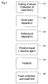
Figure 1 is a block-diagram of a silicon debris separation and recovery method according to a preferred embodiment of the invention; -
Figures 2 to 4 schematically show chemical reactions occurring with the silicon debris. - Referring to
Figure 1 , a method for separating and recovering silicon debris according to a preferred embodiment of the invention includes steps S1 to S6. - In step S1, a piece of silicon, such as an ingot, is cut or sliced in a wire sawing machine. The sawing wires are made of metal, typically steel, and are coated with a slurry consisting of a suspension of abrasive particles in a coolant liquid dispersing the particles. The abrasive particles are made of a hard material having a high surface energy, such as silicon carbide (SiC) or corundum (crystalline form of aluminum oxide). The coolant and dispersion liquid is silicon oil or polyethylene glycol, for instance. During the sawing, the silicon debris stemming from the ingot, the metal debris stemming from the sawing wires, and various contaminants (ions or soluble molecules) stemming from the wires, their coating, or from other parts of the machine become mixed with the slurry. The silicon and metal debris are in the form of particles or dust. The used slurry dropping from the sawing zone is collected in a tank as described in patent
CH 692 138 - In step S2, a solid-solid separation in liquid phase is performed, for example by centrifugation, in order to separate the large, heavy particles, having an average size above 5 µm, from the rest of the used slurry. The particles recovered in this step are essentially abrasive particles. It will be possible to reintroduce them into the sawing process.
- In step S3 a solid-liquid separation is carried out, for example by centrifugation, in order to separate from the liquid of the used slurry the remaining solid phase, consisting essentially of small, light particles, with an average size below 5 µm. The solid mixture recovered in this step essentially contains silicon and metal particles as well as fine (broken) abrasive particles. It will be possible to also reintroduce the separated liquid into the sawing process in order to reconstitute a slurry with the abrasive particles recovered.
- Steps S2 and S3 correspond to the separation steps described in the patent
CH 692 138 - When silicon is freshly cut or broken, its surface exhibits dangling bonds corresponding to unsaturated bonding sites or molecular orbitals occupied by only one electron. These sites or orbitals are highly reactive chemically, particularly in the presence of oxygen (O2) or water (H2O).
Figures 2(a), 3(a) and4(a) schematically show a piece of silicon freshly cut with dangling bonds shown by strokes at its surface. When in contact with oxygen alone, the silicon generally becomes oxidized in the manner illustrated byFigure 2(b) . When in contact with water alone, the silicon generally becomes oxidized in the manner shown inFigure 3(b) . When in contact with oxygen and water, it generally becomes oxidized first in the manner shown inFigure 4(b) and thereafter in the manner shown inFigure 4(c) . The structure represented inFigure 4(c) is that of silicon covered with a layer of native silicon oxide. As can be seen, oxygen atoms diffuse into the silicon and thus penetrate between silicon atoms. In addition, Si:OH terminations are formed and confer to this oxidized silicon a high surface energy, i.e. a large wettability. The thickness of the layer of native silicon oxide is of the order of a nanometer. - In step S4 of the method according to the invention, the solid mixture obtained in step S3, while still wet, is suspended in a liquid called flotation liquid. The amount of said liquid is so selected that the viscosity of the mixture obtained is low enough, typically below 50 mPa·s, preferably below 10 mPa·s, for instance comprised between 1 and 10 mPa·s. The mixing may be achieved with the aid of any appropriate solid-liquid mixer, and the dispersion of the solid particles in the liquid may be accelerated or improved by sonication. A reactive agent is added to this mixture or to the solid mixture prior to dilution by the flotation liquid, in order to dissolve at least in part the oxide layers of the silicon particles and produce Si:H terminations at the surface of these particles.
Figures 2(c), 3(c) ,4(d) and 4(e) show the final structure obtained by the reaction of this reactive agent on the oxidized silicon. It can be seen that the surface of the silicon particles is cleared from its oxide and becomes terminated with hydrogen atoms linked to the silicon by covalent bonds. This form of silicon that is illustrated inFigures 2(c), 3(c) ,4(d) and 4(e) is stable and has a low surface energy, in other words a low wettability. The action of the reactive agent on silicon particles that would not yet have been oxidized (Figures 2(a), 3(a) and4(a) ) would also lead to the formation of Si:H terminations. Contrary to the surfactants generally used in separation methods for modifying the surface energy of determined particles, and consisting of amphiphiles with long chains of hydrocarbons (alkyl chains) which become attached to the particles by ionic bonding, the Si:H terminations do not modify the chemical and mechanical properties of the silicon, or only negligibly. - The flotation liquid typically is an aqueous liquid, that is, water or an aqueous solution, preferably deoxygenated.
- The reactive agent is for example hydrofluoric acid (HF), also known as the fluoride of hydrogen. This acid has indeed a particular selectivity toward silicon oxide, in that it will attack the silicon oxide very rapidly, but will attack the nonoxidized part of silicon only very slowly, or hardly at all.
- Other fluorides such as sodium fluoride (NaF) or ammonium fluoride (NH4F), more precisely other water-soluble fluorides, may be used as the reactive agent. Ammonium fluoride is advantageous in the sense that it will allow the solution it forms with the flotation liquid to keep a basic pH value, thus avoiding the formation of hydrofluoric acid vapors. Such fluorides react with the water of the flotation liquid to form hydrofluoric acid which will react with the silicon oxide to form Si:H terminations as indicated hereinabove.
- The next step, S5, consists in separating the silicon particles from the other particles by a method of flotation in the flotation liquid. Flotation is a technique of separation of particles based on the difference in their surface energies. In a liquid containing bubbles of a gas, called flotation gas, that rise to the surface, the particles having a low surface energy, i.e. a surface energy lower than that of the liquid, will become attached to the gas bubbles while the particles having a high surface energy, i.e. a surface energy higher than that of the liquid, will stay suspended in the liquid and will sediment. The particles having a low surface energy thus form at the surface of the liquid a foam that can be recovered and dried. Several methods of flotation can be found in the literature, particularly improved methods such as carrier flotation, oil-assisted flotation, electroflotation, or dissolved-air flotation. Step S5 can be realized with any of these methods. However, as the flotation gas a non-oxidizing gas or gas mixture is used, i.e., a gas that will not oxidize the surface of the silicon particles during the flotation. Preferably, the flotation gas used is an inert gas such as nitrogen (N2), argon (Ar), or a mixture of the two, in order to guarantee absence of a chemical reaction between this gas and the silicon. One may also use a mixture of one of these inert gases with hydrogen (H2). In this case, the hydrogen will be able to react with the silicon in order to fill up its surface with Si:H terminations.
- In step S5, the mixing of the flotation liquid containing the silicon particles and the other particles with the flotation gas, which is in pressurized form, may be realized in different ways. One preferred embodiment of this mixing consists in pumping part of the flotation liquid into liquid-gas mixers and then remixing this gas-enriched part with the flotation liquid.
- During flotation, the silicon particles rise to the surface with the gas bubbles and form a foam. The abrasive particles as well as the metal particles sediment or remain suspended. The contaminants in the form of ions or soluble molecules remain dissolved in the liquid.
- The low surface energy of the silicon particles makes them hydrophobic. The larger surface energy of the abrasive and metal particles makes them hydrophilic or less hydrophobic than silicon. The Si:H terminations of the silicon particles in particular have a very pronounced hydrophobic character. Thus, the silicon may be readily separated from the other particles by flotation in an aqueous medium. However, the use of a nonaqueous flotation liquid is not excluded by the present invention.
- In step S6, the foam is recovered and then dried. Silicon powder of high purity is thus obtained. This powder may be packaged in an inert atmosphere to be used in various applications. It may also be compressed, sintered or melted in a furnace and then cast in order to reconstitute ingots.
- In the method described above, one can diminish the amount of reactive agent needed to deoxidize the silicon particles and lower their surface energy, by performing the sawing (step S1) in a nonoxidizing atmosphere, preferably inert (for instance, under argon or nitrogen), so as to limit oxidation of the silicon. Preferably, the other steps (S2 to S6) are also realized in a nonoxidizing or inert atmosphere.
- In a variant of the invention, separation steps S2 and S3 are suppressed, and step S4 is applied directly to the used slurry. In this case, the flotation liquid may consist of the liquid phase of the slurry, i.e. for example polyethylene glycol, diluted or not in an aqueous liquid.
- It will be noted that the present invention is applicable to other sawing techniques than wire sawing with abrasive slurry. The silicon cutting operation (step S1) may indeed be carried out with methods using a fixed abrasive, for instance wire sawing involving one or several diamond-lined metal wires, but also a sawing performed with a band saw or with an internal-diameter blade saw where the hardness of the cutting tool is once again obtained by injecting a hard material such as diamond. In these cases, an abrasive slurry generally is not used, but still a liquid is used that has the function of eliminating the heat and the silicon sawing dust created in the cutting zone. Steps S4 to S6 of the method may then be implemented for separating the silicon from undesirable debris deriving from the wear of the cutting tool.
Claims (11)
- Method for separating and recovering silicon debris from sawing waste, comprising the following steps:- treating the sawing waste so as to deoxidize the silicon debris in a manner that reduces their surface energy, said deoxidation being achieved by a chemical reaction with a reactive agent,- applying to the sawing waste thus treated a flotation method using a flotation liquid and a nonoxidizing flotation gas, and- recovering the silicon debris at the surface of the flotation liquid, characterized in that the reactive agent is a fluoride.
- Method according to claim 1, characterized in that the reactive agent is hydrofluoric acid.
- Method according to claim 1, characterized in that the reactive agent is sodium fluoride or ammonium fluoride.
- Method according to any one of claims 1 to 3, characterized in that the flotation gas is an inert gas.
- Method according to any one of claims 1 to 4, characterized in that the flotation liquid is an aqueous liquid.
- Method according to any one of claims 1 to 5, characterized in that the sawing waste is used slurry comprising abrasive particles.
- Method according to claim 6, characterized in that the abrasive particles have a surface energy higher than that of the flotation liquid.
- Method according to claim 6 or 7, characterized in that the abrasive particles consist of silicon carbide or corundum.
- Method according to any one of claims 6 to 8, characterized by further comprising, prior to said treatment step, a step of solid-solid separation, to separate part of the abrasive particles from the sawing waste.
- Method according to claim 9, characterized by further comprising, prior to said treatment step and after said solid-solid separation step, a step of solid-liquid separation, to separate the rest of the solid phase from the liquid phase of the used slurry.
- Method according to any one of claims 1 to 10, characterized in that the sawing waste stems from a step of silicon sawing realized in a nonoxidizing atmosphere.
Applications Claiming Priority (2)
| Application Number | Priority Date | Filing Date | Title |
|---|---|---|---|
| CH01965/07A CH703236B1 (en) | 2007-12-19 | 2007-12-19 | The process of recovery in silicon sawing waste. |
| PCT/IB2008/003330 WO2009081245A1 (en) | 2007-12-19 | 2008-12-04 | Method for recovering silicon from sawing waste |
Publications (2)
| Publication Number | Publication Date |
|---|---|
| EP2225040A1 EP2225040A1 (en) | 2010-09-08 |
| EP2225040B1 true EP2225040B1 (en) | 2016-08-17 |
Family
ID=40445860
Family Applications (1)
| Application Number | Title | Priority Date | Filing Date |
|---|---|---|---|
| EP08865873.7A Not-in-force EP2225040B1 (en) | 2007-12-19 | 2008-12-04 | Method for recovering silicon from sawing waste |
Country Status (6)
| Country | Link |
|---|---|
| US (1) | US8381914B2 (en) |
| EP (1) | EP2225040B1 (en) |
| KR (1) | KR101557275B1 (en) |
| CH (1) | CH703236B1 (en) |
| TW (1) | TWI460129B (en) |
| WO (1) | WO2009081245A1 (en) |
Families Citing this family (8)
| Publication number | Priority date | Publication date | Assignee | Title |
|---|---|---|---|---|
| TW201144222A (en) * | 2010-06-04 | 2011-12-16 | Hong Jing Environment Company | A method for the silicon recycling |
| CN102476800A (en) * | 2010-11-24 | 2012-05-30 | 比亚迪股份有限公司 | Smelting method of industrial silicon |
| DE102011119448B4 (en) * | 2011-11-28 | 2013-12-05 | Ralf Schefler | Process for the recovery of polyglycol ether and silicon from an adjuvant suspension |
| DE102014104322A1 (en) * | 2014-03-27 | 2015-10-01 | Khs Gmbh | Crown cap and closure device |
| FR3075776B1 (en) * | 2017-12-21 | 2020-10-02 | Rosi | SILICON GRANULES FOR THE PREPARATION OF TRICHLOROSILANE AND RELATED MANUFACTURING PROCESS |
| GB201807952D0 (en) * | 2018-05-16 | 2018-07-04 | Norwegian Univ Sci & Tech Ntnu | Silicon and silica production process |
| CN113582184B (en) * | 2021-08-06 | 2023-09-19 | 河南盛达光伏科技有限公司 | Method for purifying crushed silicon material impurities |
| KR20250106742A (en) | 2024-01-02 | 2025-07-11 | (주)로뎀기술 | System for testing and training of cognitive reaction time and providing method thereof |
Citations (1)
| Publication number | Priority date | Publication date | Assignee | Title |
|---|---|---|---|---|
| US20070209945A1 (en) * | 2004-08-12 | 2007-09-13 | Ooo "Gelios" | Method for producing silicon, method for separating silicon from molten salt and method for producing tetrafluoride |
Family Cites Families (14)
| Publication number | Priority date | Publication date | Assignee | Title |
|---|---|---|---|---|
| US4293099A (en) * | 1979-07-02 | 1981-10-06 | Silag, Inc. | Recovery of silicon carbide whiskers from coked, converted rice hulls by froth flotation |
| DE3343406A1 (en) | 1983-11-30 | 1985-06-05 | The Hanna Mining Co., Cleveland, Ohio | Method for purifying silicon |
| JPS6349291A (en) * | 1986-08-20 | 1988-03-02 | Kurita Water Ind Ltd | Flotation separation of waste water of silicon-polishing |
| JPH0839430A (en) | 1994-07-22 | 1996-02-13 | Mitsubishi Materials Corp | Abrasive recovery method from silicon cutting waste liquid |
| JP4000205B2 (en) * | 1997-05-26 | 2007-10-31 | 株式会社トクヤマ | Method for separating cutting powder from silicon waste liquid |
| CH692138A5 (en) | 1998-01-22 | 2002-02-28 | Hct Shaping Systems Sa | Cutting machine for producing thin slices of hard materials has treatment/recycling unit for slip containing abrasive and sawn particles |
| JP2001278612A (en) | 2000-03-31 | 2001-10-10 | Nippei Toyama Corp | Silicon recovery method |
| DE10056957C1 (en) | 2000-11-17 | 2002-09-05 | Metallkraft As Kristiansand | Process for manufacturing non-oxide ceramics |
| DE60112813T2 (en) * | 2001-05-29 | 2006-03-30 | Memc Electronic Materials S.P.A. | METHOD FOR TREATING A CONSUMED GLYCOL TUBE |
| US6780665B2 (en) * | 2001-08-28 | 2004-08-24 | Romain Louis Billiet | Photovoltaic cells from silicon kerf |
| JP4335541B2 (en) * | 2003-01-20 | 2009-09-30 | 隼次 芝田 | Method and apparatus for separating SiO2 particles and SiC particles, and separation and recovery SiC |
| JP2004261708A (en) | 2003-02-28 | 2004-09-24 | Kurita Water Ind Ltd | Method for coagulating waste water containing silicon fine particles and / or colloidal silica |
| DE102005023525A1 (en) * | 2005-05-21 | 2006-11-30 | Kali-Umwelttechnik Gmbh | Method for comminution of metal chips mixtures and for the alloy-specific recovery of the metal chips |
| DE102006023497B4 (en) * | 2006-05-18 | 2008-05-29 | Siltronic Ag | Process for the treatment of a semiconductor wafer |
-
2007
- 2007-12-19 CH CH01965/07A patent/CH703236B1/en not_active IP Right Cessation
-
2008
- 2008-11-03 TW TW097142362A patent/TWI460129B/en not_active IP Right Cessation
- 2008-12-04 WO PCT/IB2008/003330 patent/WO2009081245A1/en not_active Ceased
- 2008-12-04 EP EP08865873.7A patent/EP2225040B1/en not_active Not-in-force
- 2008-12-04 KR KR1020107015957A patent/KR101557275B1/en not_active Expired - Fee Related
- 2008-12-04 US US12/808,777 patent/US8381914B2/en not_active Expired - Fee Related
Patent Citations (1)
| Publication number | Priority date | Publication date | Assignee | Title |
|---|---|---|---|---|
| US20070209945A1 (en) * | 2004-08-12 | 2007-09-13 | Ooo "Gelios" | Method for producing silicon, method for separating silicon from molten salt and method for producing tetrafluoride |
Also Published As
| Publication number | Publication date |
|---|---|
| US8381914B2 (en) | 2013-02-26 |
| TW200932677A (en) | 2009-08-01 |
| CH703236B1 (en) | 2011-12-15 |
| KR101557275B1 (en) | 2015-10-05 |
| KR20100114032A (en) | 2010-10-22 |
| TWI460129B (en) | 2014-11-11 |
| US20100278707A1 (en) | 2010-11-04 |
| WO2009081245A1 (en) | 2009-07-02 |
| EP2225040A1 (en) | 2010-09-08 |
Similar Documents
| Publication | Publication Date | Title |
|---|---|---|
| US8381914B2 (en) | Method for recovering silicon from sawing waste | |
| EP1950263B1 (en) | Polishing composition and polishing method | |
| JP5539390B2 (en) | Method for recovering and purifying silicon particles from a soakerf | |
| Li et al. | Recovery of high purity Si from kerf-loss Si slurry waste by flotation method using PEA collector | |
| KR102723613B1 (en) | Method for preparing graphene oxide from expanded kish graphite | |
| KR102605373B1 (en) | Cubic boron nitride sintered body, cutting tool containing same, and method for producing cubic boron nitride sintered body | |
| Li et al. | Recovery of silicon carbide from waste silicon slurry by using flotation | |
| Chen et al. | Review on chemical mechanical polishing for atomic surfaces using advanced rare earth abrasives | |
| WO2019220176A1 (en) | A method for the manufacture of graphene oxide from kish graphite | |
| CN102962903B (en) | Method for recovering silicon particles in silicon ingot wire saw cutting process | |
| Wei et al. | Study on electrochemical corrosion and CMP of GaN in different oxidation systems | |
| JP7376215B2 (en) | Processing method for recycling silicon ingot cutting waste | |
| CN107851566B (en) | Auxiliary device for cutting silicon material, cutting method, cutting system | |
| Wang et al. | Chemically assisted machining of ceramics | |
| Kamiya et al. | Diamond and metal bonding by active solder for micro–cutting wire | |
| JP5315573B2 (en) | Processing apparatus and processing method | |
| KR101030057B1 (en) | Recycling Method of Silicon Waste and Silicon Composition Regenerated by the Method | |
| RU2120406C1 (en) | Method of recuperation of diamonds from nonconduction abrasive and cutting tool based on bronze-binding | |
| CN104603053B (en) | Sludge recycling method and granules | |
| CN103373731B (en) | Method for recycling silicon powder from diamond wire cutting slurry | |
| SU1528727A1 (en) | Method of reclaiming diamonds | |
| JP2007283248A (en) | Separation and recovery apparatus and separation and recovery method | |
| Murugesan et al. | Investigation of phosphoric acid-catalyzed silver-assisted chemical etching for upgrading metallurgical grade silicon to solar grade silicon | |
| JP2014037322A (en) | Method for regenerating a silicon sludge | |
| Hecini et al. | Silicon Carbide Recovery from Cutting Fluid Waste: Evolution of Recycling Performance for Valorization with Higher Added Value |
Legal Events
| Date | Code | Title | Description |
|---|---|---|---|
| PUAI | Public reference made under article 153(3) epc to a published international application that has entered the european phase |
Free format text: ORIGINAL CODE: 0009012 |
|
| 17P | Request for examination filed |
Effective date: 20100604 |
|
| AK | Designated contracting states |
Kind code of ref document: A1 Designated state(s): AT BE BG CH CY CZ DE DK EE ES FI FR GB GR HR HU IE IS IT LI LT LU LV MC MT NL NO PL PT RO SE SI SK TR |
|
| AX | Request for extension of the european patent |
Extension state: AL BA MK RS |
|
| RIN1 | Information on inventor provided before grant (corrected) |
Inventor name: HOFFMANN, PATRIK |
|
| DAX | Request for extension of the european patent (deleted) | ||
| GRAP | Despatch of communication of intention to grant a patent |
Free format text: ORIGINAL CODE: EPIDOSNIGR1 |
|
| RIC1 | Information provided on ipc code assigned before grant |
Ipc: C01B 33/037 20060101ALI20160310BHEP Ipc: C02F 103/34 20060101ALN20160310BHEP Ipc: C02F 1/70 20060101ALI20160310BHEP Ipc: C01B 33/02 20060101ALI20160310BHEP Ipc: B03D 1/02 20060101AFI20160310BHEP Ipc: C02F 9/00 20060101ALN20160310BHEP Ipc: B28D 5/00 20060101ALI20160310BHEP Ipc: C02F 1/24 20060101ALI20160310BHEP |
|
| INTG | Intention to grant announced |
Effective date: 20160406 |
|
| GRAS | Grant fee paid |
Free format text: ORIGINAL CODE: EPIDOSNIGR3 |
|
| GRAA | (expected) grant |
Free format text: ORIGINAL CODE: 0009210 |
|
| AK | Designated contracting states |
Kind code of ref document: B1 Designated state(s): AT BE BG CH CY CZ DE DK EE ES FI FR GB GR HR HU IE IS IT LI LT LU LV MC MT NL NO PL PT RO SE SI SK TR |
|
| REG | Reference to a national code |
Ref country code: GB Ref legal event code: FG4D |
|
| REG | Reference to a national code |
Ref country code: CH Ref legal event code: EP |
|
| REG | Reference to a national code |
Ref country code: IE Ref legal event code: FG4D |
|
| REG | Reference to a national code |
Ref country code: AT Ref legal event code: REF Ref document number: 820543 Country of ref document: AT Kind code of ref document: T Effective date: 20160915 |
|
| REG | Reference to a national code |
Ref country code: DE Ref legal event code: R096 Ref document number: 602008045792 Country of ref document: DE |
|
| REG | Reference to a national code |
Ref country code: CH Ref legal event code: NV Representative=s name: MICHELI AND CIE SA, CH |
|
| REG | Reference to a national code |
Ref country code: NL Ref legal event code: MP Effective date: 20160817 |
|
| REG | Reference to a national code |
Ref country code: FR Ref legal event code: PLFP Year of fee payment: 9 |
|
| REG | Reference to a national code |
Ref country code: LT Ref legal event code: MG4D |
|
| REG | Reference to a national code |
Ref country code: AT Ref legal event code: MK05 Ref document number: 820543 Country of ref document: AT Kind code of ref document: T Effective date: 20160817 |
|
| PG25 | Lapsed in a contracting state [announced via postgrant information from national office to epo] |
Ref country code: IT Free format text: LAPSE BECAUSE OF FAILURE TO SUBMIT A TRANSLATION OF THE DESCRIPTION OR TO PAY THE FEE WITHIN THE PRESCRIBED TIME-LIMIT Effective date: 20160817 Ref country code: NL Free format text: LAPSE BECAUSE OF FAILURE TO SUBMIT A TRANSLATION OF THE DESCRIPTION OR TO PAY THE FEE WITHIN THE PRESCRIBED TIME-LIMIT Effective date: 20160817 Ref country code: FI Free format text: LAPSE BECAUSE OF FAILURE TO SUBMIT A TRANSLATION OF THE DESCRIPTION OR TO PAY THE FEE WITHIN THE PRESCRIBED TIME-LIMIT Effective date: 20160817 Ref country code: NO Free format text: LAPSE BECAUSE OF FAILURE TO SUBMIT A TRANSLATION OF THE DESCRIPTION OR TO PAY THE FEE WITHIN THE PRESCRIBED TIME-LIMIT Effective date: 20161117 Ref country code: LT Free format text: LAPSE BECAUSE OF FAILURE TO SUBMIT A TRANSLATION OF THE DESCRIPTION OR TO PAY THE FEE WITHIN THE PRESCRIBED TIME-LIMIT Effective date: 20160817 Ref country code: HR Free format text: LAPSE BECAUSE OF FAILURE TO SUBMIT A TRANSLATION OF THE DESCRIPTION OR TO PAY THE FEE WITHIN THE PRESCRIBED TIME-LIMIT Effective date: 20160817 |
|
| PG25 | Lapsed in a contracting state [announced via postgrant information from national office to epo] |
Ref country code: LV Free format text: LAPSE BECAUSE OF FAILURE TO SUBMIT A TRANSLATION OF THE DESCRIPTION OR TO PAY THE FEE WITHIN THE PRESCRIBED TIME-LIMIT Effective date: 20160817 Ref country code: GR Free format text: LAPSE BECAUSE OF FAILURE TO SUBMIT A TRANSLATION OF THE DESCRIPTION OR TO PAY THE FEE WITHIN THE PRESCRIBED TIME-LIMIT Effective date: 20161118 Ref country code: AT Free format text: LAPSE BECAUSE OF FAILURE TO SUBMIT A TRANSLATION OF THE DESCRIPTION OR TO PAY THE FEE WITHIN THE PRESCRIBED TIME-LIMIT Effective date: 20160817 Ref country code: ES Free format text: LAPSE BECAUSE OF FAILURE TO SUBMIT A TRANSLATION OF THE DESCRIPTION OR TO PAY THE FEE WITHIN THE PRESCRIBED TIME-LIMIT Effective date: 20160817 Ref country code: PT Free format text: LAPSE BECAUSE OF FAILURE TO SUBMIT A TRANSLATION OF THE DESCRIPTION OR TO PAY THE FEE WITHIN THE PRESCRIBED TIME-LIMIT Effective date: 20161219 Ref country code: PL Free format text: LAPSE BECAUSE OF FAILURE TO SUBMIT A TRANSLATION OF THE DESCRIPTION OR TO PAY THE FEE WITHIN THE PRESCRIBED TIME-LIMIT Effective date: 20160817 Ref country code: SE Free format text: LAPSE BECAUSE OF FAILURE TO SUBMIT A TRANSLATION OF THE DESCRIPTION OR TO PAY THE FEE WITHIN THE PRESCRIBED TIME-LIMIT Effective date: 20160817 |
|
| PG25 | Lapsed in a contracting state [announced via postgrant information from national office to epo] |
Ref country code: EE Free format text: LAPSE BECAUSE OF FAILURE TO SUBMIT A TRANSLATION OF THE DESCRIPTION OR TO PAY THE FEE WITHIN THE PRESCRIBED TIME-LIMIT Effective date: 20160817 Ref country code: RO Free format text: LAPSE BECAUSE OF FAILURE TO SUBMIT A TRANSLATION OF THE DESCRIPTION OR TO PAY THE FEE WITHIN THE PRESCRIBED TIME-LIMIT Effective date: 20160817 |
|
| REG | Reference to a national code |
Ref country code: DE Ref legal event code: R097 Ref document number: 602008045792 Country of ref document: DE |
|
| PG25 | Lapsed in a contracting state [announced via postgrant information from national office to epo] |
Ref country code: SK Free format text: LAPSE BECAUSE OF FAILURE TO SUBMIT A TRANSLATION OF THE DESCRIPTION OR TO PAY THE FEE WITHIN THE PRESCRIBED TIME-LIMIT Effective date: 20160817 Ref country code: BE Free format text: LAPSE BECAUSE OF FAILURE TO SUBMIT A TRANSLATION OF THE DESCRIPTION OR TO PAY THE FEE WITHIN THE PRESCRIBED TIME-LIMIT Effective date: 20160817 Ref country code: DK Free format text: LAPSE BECAUSE OF FAILURE TO SUBMIT A TRANSLATION OF THE DESCRIPTION OR TO PAY THE FEE WITHIN THE PRESCRIBED TIME-LIMIT Effective date: 20160817 Ref country code: BG Free format text: LAPSE BECAUSE OF FAILURE TO SUBMIT A TRANSLATION OF THE DESCRIPTION OR TO PAY THE FEE WITHIN THE PRESCRIBED TIME-LIMIT Effective date: 20161117 Ref country code: CZ Free format text: LAPSE BECAUSE OF FAILURE TO SUBMIT A TRANSLATION OF THE DESCRIPTION OR TO PAY THE FEE WITHIN THE PRESCRIBED TIME-LIMIT Effective date: 20160817 |
|
| PLBE | No opposition filed within time limit |
Free format text: ORIGINAL CODE: 0009261 |
|
| STAA | Information on the status of an ep patent application or granted ep patent |
Free format text: STATUS: NO OPPOSITION FILED WITHIN TIME LIMIT |
|
| REG | Reference to a national code |
Ref country code: DE Ref legal event code: R119 Ref document number: 602008045792 Country of ref document: DE |
|
| 26N | No opposition filed |
Effective date: 20170518 |
|
| GBPC | Gb: european patent ceased through non-payment of renewal fee |
Effective date: 20161204 |
|
| PG25 | Lapsed in a contracting state [announced via postgrant information from national office to epo] |
Ref country code: SI Free format text: LAPSE BECAUSE OF FAILURE TO SUBMIT A TRANSLATION OF THE DESCRIPTION OR TO PAY THE FEE WITHIN THE PRESCRIBED TIME-LIMIT Effective date: 20160817 |
|
| PG25 | Lapsed in a contracting state [announced via postgrant information from national office to epo] |
Ref country code: MC Free format text: LAPSE BECAUSE OF FAILURE TO SUBMIT A TRANSLATION OF THE DESCRIPTION OR TO PAY THE FEE WITHIN THE PRESCRIBED TIME-LIMIT Effective date: 20160817 |
|
| REG | Reference to a national code |
Ref country code: IE Ref legal event code: MM4A |
|
| PG25 | Lapsed in a contracting state [announced via postgrant information from national office to epo] |
Ref country code: LU Free format text: LAPSE BECAUSE OF NON-PAYMENT OF DUE FEES Effective date: 20161204 |
|
| PG25 | Lapsed in a contracting state [announced via postgrant information from national office to epo] |
Ref country code: IE Free format text: LAPSE BECAUSE OF NON-PAYMENT OF DUE FEES Effective date: 20161204 Ref country code: DE Free format text: LAPSE BECAUSE OF NON-PAYMENT OF DUE FEES Effective date: 20170701 Ref country code: GB Free format text: LAPSE BECAUSE OF NON-PAYMENT OF DUE FEES Effective date: 20161204 |
|
| REG | Reference to a national code |
Ref country code: FR Ref legal event code: PLFP Year of fee payment: 10 |
|
| PGFP | Annual fee paid to national office [announced via postgrant information from national office to epo] |
Ref country code: FR Payment date: 20171221 Year of fee payment: 10 |
|
| PGFP | Annual fee paid to national office [announced via postgrant information from national office to epo] |
Ref country code: CH Payment date: 20171114 Year of fee payment: 10 |
|
| PG25 | Lapsed in a contracting state [announced via postgrant information from national office to epo] |
Ref country code: HU Free format text: LAPSE BECAUSE OF FAILURE TO SUBMIT A TRANSLATION OF THE DESCRIPTION OR TO PAY THE FEE WITHIN THE PRESCRIBED TIME-LIMIT; INVALID AB INITIO Effective date: 20081204 Ref country code: CY Free format text: LAPSE BECAUSE OF FAILURE TO SUBMIT A TRANSLATION OF THE DESCRIPTION OR TO PAY THE FEE WITHIN THE PRESCRIBED TIME-LIMIT Effective date: 20160817 |
|
| PG25 | Lapsed in a contracting state [announced via postgrant information from national office to epo] |
Ref country code: TR Free format text: LAPSE BECAUSE OF FAILURE TO SUBMIT A TRANSLATION OF THE DESCRIPTION OR TO PAY THE FEE WITHIN THE PRESCRIBED TIME-LIMIT Effective date: 20160817 Ref country code: IS Free format text: LAPSE BECAUSE OF FAILURE TO SUBMIT A TRANSLATION OF THE DESCRIPTION OR TO PAY THE FEE WITHIN THE PRESCRIBED TIME-LIMIT Effective date: 20160817 |
|
| PG25 | Lapsed in a contracting state [announced via postgrant information from national office to epo] |
Ref country code: MT Free format text: LAPSE BECAUSE OF NON-PAYMENT OF DUE FEES Effective date: 20161204 |
|
| REG | Reference to a national code |
Ref country code: CH Ref legal event code: PL |
|
| PG25 | Lapsed in a contracting state [announced via postgrant information from national office to epo] |
Ref country code: FR Free format text: LAPSE BECAUSE OF NON-PAYMENT OF DUE FEES Effective date: 20181231 |
|
| PG25 | Lapsed in a contracting state [announced via postgrant information from national office to epo] |
Ref country code: CH Free format text: LAPSE BECAUSE OF NON-PAYMENT OF DUE FEES Effective date: 20181231 Ref country code: LI Free format text: LAPSE BECAUSE OF NON-PAYMENT OF DUE FEES Effective date: 20181231 |