EP2224162A1 - Lichtemittierende Vorrichtung mit einer Solarglühlampe - Google Patents
Lichtemittierende Vorrichtung mit einer Solarglühlampe Download PDFInfo
- Publication number
- EP2224162A1 EP2224162A1 EP09010509A EP09010509A EP2224162A1 EP 2224162 A1 EP2224162 A1 EP 2224162A1 EP 09010509 A EP09010509 A EP 09010509A EP 09010509 A EP09010509 A EP 09010509A EP 2224162 A1 EP2224162 A1 EP 2224162A1
- Authority
- EP
- European Patent Office
- Prior art keywords
- light emitting
- emitting device
- bottle
- housing
- solar
- Prior art date
- Legal status (The legal status is an assumption and is not a legal conclusion. Google has not performed a legal analysis and makes no representation as to the accuracy of the status listed.)
- Withdrawn
Links
- 239000012530 fluid Substances 0.000 claims description 4
- XLYOFNOQVPJJNP-UHFFFAOYSA-N water Substances O XLYOFNOQVPJJNP-UHFFFAOYSA-N 0.000 claims description 2
- 239000000126 substance Substances 0.000 description 8
- 238000010586 diagram Methods 0.000 description 4
- 230000007613 environmental effect Effects 0.000 description 3
- WHXSMMKQMYFTQS-UHFFFAOYSA-N Lithium Chemical compound [Li] WHXSMMKQMYFTQS-UHFFFAOYSA-N 0.000 description 2
- 238000006243 chemical reaction Methods 0.000 description 2
- 230000005611 electricity Effects 0.000 description 2
- 229910052744 lithium Inorganic materials 0.000 description 2
- 229910005813 NiMH Inorganic materials 0.000 description 1
- 239000002253 acid Substances 0.000 description 1
- 230000001419 dependent effect Effects 0.000 description 1
- 238000011161 development Methods 0.000 description 1
- 230000018109 developmental process Effects 0.000 description 1
- 230000005674 electromagnetic induction Effects 0.000 description 1
- 238000005516 engineering process Methods 0.000 description 1
- 238000005286 illumination Methods 0.000 description 1
- QSHDDOUJBYECFT-UHFFFAOYSA-N mercury Chemical compound [Hg] QSHDDOUJBYECFT-UHFFFAOYSA-N 0.000 description 1
- 229910052753 mercury Inorganic materials 0.000 description 1
- 230000003287 optical effect Effects 0.000 description 1
- 238000004064 recycling Methods 0.000 description 1
Images





Classifications
-
- F—MECHANICAL ENGINEERING; LIGHTING; HEATING; WEAPONS; BLASTING
- F21—LIGHTING
- F21S—NON-PORTABLE LIGHTING DEVICES; SYSTEMS THEREOF; VEHICLE LIGHTING DEVICES SPECIALLY ADAPTED FOR VEHICLE EXTERIORS
- F21S9/00—Lighting devices with a built-in power supply; Systems employing lighting devices with a built-in power supply
- F21S9/02—Lighting devices with a built-in power supply; Systems employing lighting devices with a built-in power supply the power supply being a battery or accumulator
- F21S9/03—Lighting devices with a built-in power supply; Systems employing lighting devices with a built-in power supply the power supply being a battery or accumulator rechargeable by exposure to light
- F21S9/037—Lighting devices with a built-in power supply; Systems employing lighting devices with a built-in power supply the power supply being a battery or accumulator rechargeable by exposure to light the solar unit and the lighting unit being located within or on the same housing
-
- B—PERFORMING OPERATIONS; TRANSPORTING
- B65—CONVEYING; PACKING; STORING; HANDLING THIN OR FILAMENTARY MATERIAL
- B65D—CONTAINERS FOR STORAGE OR TRANSPORT OF ARTICLES OR MATERIALS, e.g. BAGS, BARRELS, BOTTLES, BOXES, CANS, CARTONS, CRATES, DRUMS, JARS, TANKS, HOPPERS, FORWARDING CONTAINERS; ACCESSORIES, CLOSURES, OR FITTINGS THEREFOR; PACKAGING ELEMENTS; PACKAGES
- B65D51/00—Closures not otherwise provided for
- B65D51/24—Closures not otherwise provided for combined or co-operating with auxiliary devices for non-closing purposes
- B65D51/248—Closures not otherwise provided for combined or co-operating with auxiliary devices for non-closing purposes the closure being provided with transient audible or visual signaling means, e.g. for indicating dispensing, or other illuminating or acoustic devices, e.g. whistles
-
- F—MECHANICAL ENGINEERING; LIGHTING; HEATING; WEAPONS; BLASTING
- F21—LIGHTING
- F21V—FUNCTIONAL FEATURES OR DETAILS OF LIGHTING DEVICES OR SYSTEMS THEREOF; STRUCTURAL COMBINATIONS OF LIGHTING DEVICES WITH OTHER ARTICLES, NOT OTHERWISE PROVIDED FOR
- F21V33/00—Structural combinations of lighting devices with other articles, not otherwise provided for
- F21V33/0004—Personal or domestic articles
- F21V33/0024—Household or table equipment
- F21V33/0036—Table-ware or table equipment, e.g. dishes, cutlery or trays
-
- F—MECHANICAL ENGINEERING; LIGHTING; HEATING; WEAPONS; BLASTING
- F21—LIGHTING
- F21Y—INDEXING SCHEME ASSOCIATED WITH SUBCLASSES F21K, F21L, F21S and F21V, RELATING TO THE FORM OR THE KIND OF THE LIGHT SOURCES OR OF THE COLOUR OF THE LIGHT EMITTED
- F21Y2101/00—Point-like light sources
-
- F—MECHANICAL ENGINEERING; LIGHTING; HEATING; WEAPONS; BLASTING
- F21—LIGHTING
- F21Y—INDEXING SCHEME ASSOCIATED WITH SUBCLASSES F21K, F21L, F21S and F21V, RELATING TO THE FORM OR THE KIND OF THE LIGHT SOURCES OR OF THE COLOUR OF THE LIGHT EMITTED
- F21Y2115/00—Light-generating elements of semiconductor light sources
- F21Y2115/10—Light-emitting diodes [LED]
-
- F—MECHANICAL ENGINEERING; LIGHTING; HEATING; WEAPONS; BLASTING
- F21—LIGHTING
- F21Y—INDEXING SCHEME ASSOCIATED WITH SUBCLASSES F21K, F21L, F21S and F21V, RELATING TO THE FORM OR THE KIND OF THE LIGHT SOURCES OR OF THE COLOUR OF THE LIGHT EMITTED
- F21Y2115/00—Light-generating elements of semiconductor light sources
- F21Y2115/30—Semiconductor lasers
-
- Y—GENERAL TAGGING OF NEW TECHNOLOGICAL DEVELOPMENTS; GENERAL TAGGING OF CROSS-SECTIONAL TECHNOLOGIES SPANNING OVER SEVERAL SECTIONS OF THE IPC; TECHNICAL SUBJECTS COVERED BY FORMER USPC CROSS-REFERENCE ART COLLECTIONS [XRACs] AND DIGESTS
- Y02—TECHNOLOGIES OR APPLICATIONS FOR MITIGATION OR ADAPTATION AGAINST CLIMATE CHANGE
- Y02W—CLIMATE CHANGE MITIGATION TECHNOLOGIES RELATED TO WASTEWATER TREATMENT OR WASTE MANAGEMENT
- Y02W30/00—Technologies for solid waste management
- Y02W30/50—Reuse, recycling or recovery technologies
- Y02W30/82—Recycling of waste of electrical or electronic equipment [WEEE]
Definitions
- the present invention relates to a light emitting device according to the pre-characterizing clause of claim 1.
- a chemical battery can transfer chemical energy into electric energy.
- the chemical battery includes advantages of portability, high energy density, no noise, and so on, so the chemical battery is widely used in a notebook computer, and portable electronic apparatus, such as mobile phones and digital cameras.
- There are two kinds of the chemical battery a non-rechargeable battery and a rechargeable battery.
- the non-rechargeable battery only can be used once, and chemical energy can not be supplied by charging the battery.
- the non-rechargeable batteries are a dry battery, a mercury battery, an alkaline battery, and so on.
- the rechargeable battery can be used repeatedly, and chemical energy can be supplied by charging the battery.
- the rechargeable batteries are a lead-acid battery, a NiMH battery, a lithium battery, an advanced lithium battery, and so on.
- the non-rechargeable battery and the rechargeable battery run out of electricity
- the non-rechargeable battery and the rechargeable battery can not provide electricity anymore at the moment, causing inconvenient to operate electronic apparatuses.
- the chemical battery has disadvantages of difficulty of recycling, pollution, and low charging speed.
- the solar charger involves utilizing a solar panel to absorb solar energy so as to convert the solar energy into electric energy.
- the hand-powered device involves utilizing a motor that may convert mechanical energy into electric energy, meaning that a user may rotate a drive shaft of the motor to make electromagnetic induction occur in the motor to generate the electric energy.
- a user needs to provide mechanical energy so that the motor may be driven to generate electric energy, such as shaking the hand-powered device or rotating the drive shaft of the hand-powered device.
- the present invention aims at providing a light emitting device with a solar bulb capable of converting solar energy into electric energy for lightening.
- the claimed light emitting device includes a bottle, and a solar bulb for capping with the bottle.
- the solar bulb includes a housing, a solar panel disposed on the housing for converting solar energy into electric energy, a rechargeable battery module installed inside the housing for storing the electric energy generated by the solar panel, a light source installed inside the housing for emitting light to the bottle, and a control circuit installed inside the housing and coupled to the solar panel and the rechargeable battery module for transmitting the electric energy from the rechargeable battery module to the light source.
- FIG.1 is a perspective drawing of a light emitting device 100 according to a preferred embodiment of the present invention.
- the light emitting device 100 includes a bottle 102, and a solar bulb 104 capped with the bottle 102.
- the solar bulb 104 can be screwed on the bottle 102 as a bottle cap.
- Fluid, such as water, can be contained inside the bottle 102.
- the bottle 102 includes alternate a plurality of protruding parts 1021 and a plurality of sunken parts 1022.
- the disposition and the amount of the plurality of protruding parts 1021 and the plurality of sunken parts 1022 are not limited to this embodiment and can be designed upon actual demand.
- the bottle 102 also can include a smooth surface instead.
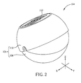
- FIG.2 to FIG.4 are perspective drawings at different views of the solar bulb 104 according to the preferred embodiment of the present invention.
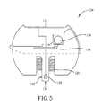
- FIG.5 is a diagram illustrating inner components of the solar bulb 104 according to the preferred embodiment of the present invention.
- the solar bulb 104 includes a housing 106.
- the housing 106 includes a base 108 and a casing 110 connected to the base 108 in a rotatable manner.
- the casing 110 and the base 108 can be hemispheric structures substantially.
- the solar bulb 104 further includes a solar panel 112 disposed on the casing 110 of the housing 106 for converting solar energy into electric energy.
- the solar bulb 104 further includes a rechargeable battery module 114 installed inside the housing 106 for storing the electric energy generated by the solar panel 112.
- the solar bulb 104 further includes a light source 116 installed inside the housing 106 for emitting light to the bottle 102.
- the light source 116 can be a light emitting diode (LED), a laser diode, a lamp, and combination thereof.
- the solar bulb 104 further includes a control circuit 118 installed inside the housing 106 and coupled to the solar panel 112 and the rechargeable battery module 114 for transmitting the electric energy from the rechargeable battery module 114 to the light source 116.
- the control circuit 118 can be formed on a circuit board, such as a printed circuit board.
- a thread 120 is formed on an inner surface of the housing 106 of the solar bulb 104 for screwing the bottle 102 so that the solar bulb 104 is a bottle cap for capping the bottle 102.
- the base 108 of the housing 106 includes a lance structure 122 for inserting into a mouth of the bottle 102, and the light source 116 is disposed inside the lance structure 122 so that the light source 116 is inserted into the bottle 102 when the bottle 102 is capped with the solar bulb 104.
- a light magnifying unit 124 is disposed on an end of the lance structure 122 and on an optical path of the light emitting to the bottle 102 from the light source 116.
- the light magnifying unit 124 is utilized for magnifying the light emitted from the light source 116.
- the light magnifying unit 124 can be a lens structure formed on the end of the solar bulb 104.
- the plurality of protruding parts 1021 and the plurality of sunken parts 1022 of the bottle 102 and the fluid contained inside the bottle 102 can refract the light emitted from the light source 116 to cause to glitter.
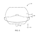
- FIG.6 to FIG.8 are diagrams illustrating the casing 110 rotating relative to the base 108 in different degrees of freedom according to the preferred embodiment of the present invention.
- the casing 110 is connected to the base 108 in a rotatable manner around the Z-axis direction. That is, the casing 110 is swivelable relative to the base 108 at 360 degrees.
- the casing 110 is connected to the base 108 in a rotatable manner on the Y-Z plane clockwise and counterclockwise (around the X-axis direction) respectively. That is, the casing 110 is swingable relative to the base 108.
- the solar panel 112 disposed on the casing 110 can be rotated to orient the sun so as to increase solar energy conversion efficiency.
- the rotary mechanism of the casing 100 is not limited to this embodiment and can be designed upon actual demand.
- the light emitting device of the present invention includes the solar bulb capable of converting solar energy into electric energy for lightening.
- the present invention provides an environmental design of illumination devices.
Landscapes
- Engineering & Computer Science (AREA)
- General Engineering & Computer Science (AREA)
- Mechanical Engineering (AREA)
- Life Sciences & Earth Sciences (AREA)
- Sustainable Development (AREA)
- Non-Portable Lighting Devices Or Systems Thereof (AREA)
- Arrangement Of Elements, Cooling, Sealing, Or The Like Of Lighting Devices (AREA)
Applications Claiming Priority (1)
| Application Number | Priority Date | Filing Date | Title |
|---|---|---|---|
| US12/394,014 US20100214774A1 (en) | 2009-02-26 | 2009-02-26 | Light emitting device with a solar bulb |
Publications (1)
| Publication Number | Publication Date |
|---|---|
| EP2224162A1 true EP2224162A1 (de) | 2010-09-01 |
Family
ID=42214562
Family Applications (1)
| Application Number | Title | Priority Date | Filing Date |
|---|---|---|---|
| EP09010509A Withdrawn EP2224162A1 (de) | 2009-02-26 | 2009-08-14 | Lichtemittierende Vorrichtung mit einer Solarglühlampe |
Country Status (3)
| Country | Link |
|---|---|
| US (1) | US20100214774A1 (de) |
| EP (1) | EP2224162A1 (de) |
| TW (1) | TW201031864A (de) |
Cited By (6)
| Publication number | Priority date | Publication date | Assignee | Title |
|---|---|---|---|---|
| WO2013164748A1 (en) * | 2012-05-02 | 2013-11-07 | Johan Erasmus | Solar light unit |
| WO2014031555A1 (en) * | 2012-08-20 | 2014-02-27 | D.Light Design, Inc. | Solar powered light having an unobstructed light path |
| EP2854486A1 (de) * | 2013-09-30 | 2015-04-01 | FutureDynamics GmbH | Flächenelement zum Leuchten und Erzeugen sowie Speichern von Energie |
| CN104840113A (zh) * | 2015-06-10 | 2015-08-19 | 上海沣奇实业有限公司 | 太阳能电动炫彩搅拌杯 |
| EP2941589A4 (de) * | 2013-01-03 | 2016-07-13 | Mpowerd Inc | Durch solarstrom betriebene lampe |
| US9799018B2 (en) | 2011-03-08 | 2017-10-24 | D.Light Design, Inc. | Systems and methods for activation and deactivation of appliances |
Families Citing this family (14)
| Publication number | Priority date | Publication date | Assignee | Title |
|---|---|---|---|---|
| MX2013005267A (es) * | 2010-11-13 | 2013-08-21 | Stephen Katsaros | Lampara ajustable de carga solar. |
| US9089011B2 (en) * | 2012-02-03 | 2015-07-21 | Sonopro Power & Light, Inc. | Enablement period controlled lighting appliance |
| CN103926705A (zh) * | 2013-01-15 | 2014-07-16 | 江南大学 | 一种光路调节与照明装置 |
| US9410666B2 (en) | 2014-01-30 | 2016-08-09 | Karibu Solar Pauer Inc. | Modular lamp |
| CL2014001840A1 (es) * | 2014-07-11 | 2015-01-02 | Sulilab Spa | Luminaria solar como componente base para aplicaciones de iluminacion, fijable en accesorios iluminables del tipo botellas o lamparas formada por un cuerpo cilindrico de altura la mitad de su diametro, con: una carcasa superior, un panel intermedio con un microprocesador, baterias y generador de luz, y una carcasa traslucida inferior de cuerpo tronco conico y una perforacion central cilindrica, roscada interiormente. |
| US9080736B1 (en) | 2015-01-22 | 2015-07-14 | Mpowerd Inc. | Portable solar-powered devices |
| CN204444675U (zh) * | 2015-03-06 | 2015-07-08 | 温州市盛博科技有限公司 | 便携式硅胶夜光杯 |
| WO2017051220A1 (en) * | 2015-09-25 | 2017-03-30 | The Green Energy Warehouse Cc T/A Suntoy | Solar lighting arrangement |
| GB2549764B (en) * | 2016-04-28 | 2020-06-17 | John Axten Darrel | Improvements to a bottle cap |
| US10180221B1 (en) | 2018-02-12 | 2019-01-15 | Mpowerd Inc. | Modular solar-powered lighting devices and components thereof |
| US10704746B2 (en) | 2018-10-19 | 2020-07-07 | Mpowerd Inc. | Portable lighting devices with wireless connectivity |
| CN110466877B (zh) * | 2019-08-21 | 2024-04-26 | 惠州康耐特电热制品有限公司 | 一种可充电的usb酒瓶塞灯 |
| US11708952B2 (en) * | 2021-05-30 | 2023-07-25 | Sathurukulasingam Shanthikumar | Portable solar-powered camping light |
| CN222824226U (zh) * | 2024-08-02 | 2025-05-02 | 深圳市飞鹤电子有限公司 | 一种酒瓶灯 |
Citations (3)
| Publication number | Priority date | Publication date | Assignee | Title |
|---|---|---|---|---|
| US20070121317A1 (en) * | 2005-11-25 | 2007-05-31 | Giant Asia Energy Service Co. | Solar lighting device having color and brightness control mechanism |
| US20070133194A1 (en) * | 2005-12-01 | 2007-06-14 | Peixing Deng | Lighting ashtray apparatus using solar energy |
| US7318656B1 (en) * | 2005-08-11 | 2008-01-15 | Frantz Merine | Illuminating bottle closure |
Family Cites Families (8)
| Publication number | Priority date | Publication date | Assignee | Title |
|---|---|---|---|---|
| US6086216A (en) * | 1998-12-22 | 2000-07-11 | Goldfarb; Eric A. | Bottle lantern |
| US20040004829A1 (en) * | 2001-09-07 | 2004-01-08 | Nini Policappelli | Illuminating, heating or cooling a consumer product |
| US20030063460A1 (en) * | 2001-09-28 | 2003-04-03 | Craig P. Nadel | Device and method for illuminating liquid containers internally |
| US20060061985A1 (en) * | 2004-09-23 | 2006-03-23 | John Elkins | Drinking vessel with auditory and visual stimulation |
| US7448347B2 (en) * | 2005-12-16 | 2008-11-11 | Simon Nicholas Richmond | Illuminated hummingbird feeder |
| US20070014100A1 (en) * | 2005-07-15 | 2007-01-18 | Duke Perez | Baby bottle with illumination |
| US7740368B2 (en) * | 2008-01-08 | 2010-06-22 | Ming Chiang | Cap with a light emitting diode (LED) for illuminating a beverage container |
| US7771073B2 (en) * | 2008-02-27 | 2010-08-10 | Co-Union Industry Co., Ltd. | Luminous water bottle |
-
2009
- 2009-02-26 US US12/394,014 patent/US20100214774A1/en not_active Abandoned
- 2009-08-14 EP EP09010509A patent/EP2224162A1/de not_active Withdrawn
-
2010
- 2010-02-26 TW TW099105647A patent/TW201031864A/zh unknown
Patent Citations (3)
| Publication number | Priority date | Publication date | Assignee | Title |
|---|---|---|---|---|
| US7318656B1 (en) * | 2005-08-11 | 2008-01-15 | Frantz Merine | Illuminating bottle closure |
| US20070121317A1 (en) * | 2005-11-25 | 2007-05-31 | Giant Asia Energy Service Co. | Solar lighting device having color and brightness control mechanism |
| US20070133194A1 (en) * | 2005-12-01 | 2007-06-14 | Peixing Deng | Lighting ashtray apparatus using solar energy |
Cited By (6)
| Publication number | Priority date | Publication date | Assignee | Title |
|---|---|---|---|---|
| US9799018B2 (en) | 2011-03-08 | 2017-10-24 | D.Light Design, Inc. | Systems and methods for activation and deactivation of appliances |
| WO2013164748A1 (en) * | 2012-05-02 | 2013-11-07 | Johan Erasmus | Solar light unit |
| WO2014031555A1 (en) * | 2012-08-20 | 2014-02-27 | D.Light Design, Inc. | Solar powered light having an unobstructed light path |
| EP2941589A4 (de) * | 2013-01-03 | 2016-07-13 | Mpowerd Inc | Durch solarstrom betriebene lampe |
| EP2854486A1 (de) * | 2013-09-30 | 2015-04-01 | FutureDynamics GmbH | Flächenelement zum Leuchten und Erzeugen sowie Speichern von Energie |
| CN104840113A (zh) * | 2015-06-10 | 2015-08-19 | 上海沣奇实业有限公司 | 太阳能电动炫彩搅拌杯 |
Also Published As
| Publication number | Publication date |
|---|---|
| TW201031864A (en) | 2010-09-01 |
| US20100214774A1 (en) | 2010-08-26 |
Similar Documents
| Publication | Publication Date | Title |
|---|---|---|
| EP2224162A1 (de) | Lichtemittierende Vorrichtung mit einer Solarglühlampe | |
| US9410666B2 (en) | Modular lamp | |
| US8138618B2 (en) | Oscillating power generator with a ratchet mechanism | |
| CN101299545A (zh) | 便携式双模充电器 | |
| CN101510626A (zh) | 带发电功能的便携式电子装置 | |
| US8525358B2 (en) | Power module and electronic device using the same | |
| KR20080080756A (ko) | 휴대용 자가발전 손전등 | |
| CN201557479U (zh) | 一种手拧充电式电蚊拍 | |
| CN201062720Y (zh) | 用透镜使多个led聚光的手拎充电式的储能手电筒 | |
| RU91821U1 (ru) | Универсальный футляр для электронных устройств | |
| CN105048615A (zh) | 一种自主发电的充电宝 | |
| CN207444130U (zh) | 智能驱鸟器及监控系统 | |
| CN201207626Y (zh) | 具有聚光功能的太阳能遥控装置 | |
| CN202691624U (zh) | 一种多功能电筒 | |
| CN206115015U (zh) | 一种便携式显微镜 | |
| CN110581582A (zh) | 发电装置和移动电源 | |
| TWM465556U (zh) | 太陽能模組 | |
| TWI447922B (zh) | 太陽能電池裝置及可攜式電子裝置 | |
| CN114263859A (zh) | 一种具有自发电功能的便携式led手电筒 | |
| CN216345910U (zh) | 使用灵活的多功能台灯 | |
| CN201487582U (zh) | 多功能防爆工作灯 | |
| KR200355134Y1 (ko) | 발전/충전 장치 | |
| CN207213712U (zh) | 一种多功能手电筒 | |
| CN213846734U (zh) | 电子设备 | |
| CN209298963U (zh) | 智能钥匙 |
Legal Events
| Date | Code | Title | Description |
|---|---|---|---|
| PUAI | Public reference made under article 153(3) epc to a published international application that has entered the european phase |
Free format text: ORIGINAL CODE: 0009012 |
|
| AK | Designated contracting states |
Kind code of ref document: A1 Designated state(s): AT BE BG CH CY CZ DE DK EE ES FI FR GB GR HR HU IE IS IT LI LT LU LV MC MK MT NL NO PL PT RO SE SI SK SM TR |
|
| AX | Request for extension of the european patent |
Extension state: AL BA RS |
|
| STAA | Information on the status of an ep patent application or granted ep patent |
Free format text: STATUS: THE APPLICATION IS DEEMED TO BE WITHDRAWN |
|
| 18D | Application deemed to be withdrawn |
Effective date: 20110302 |