EP2224133A1 - Seal structure and compressor - Google Patents
Seal structure and compressor Download PDFInfo
- Publication number
- EP2224133A1 EP2224133A1 EP08854990A EP08854990A EP2224133A1 EP 2224133 A1 EP2224133 A1 EP 2224133A1 EP 08854990 A EP08854990 A EP 08854990A EP 08854990 A EP08854990 A EP 08854990A EP 2224133 A1 EP2224133 A1 EP 2224133A1
- Authority
- EP
- European Patent Office
- Prior art keywords
- component
- muffler
- boss portion
- side wall
- end surface
- Prior art date
- Legal status (The legal status is an assumption and is not a legal conclusion. Google has not performed a legal analysis and makes no representation as to the accuracy of the status listed.)
- Granted
Links
Images





Classifications
-
- F—MECHANICAL ENGINEERING; LIGHTING; HEATING; WEAPONS; BLASTING
- F04—POSITIVE - DISPLACEMENT MACHINES FOR LIQUIDS; PUMPS FOR LIQUIDS OR ELASTIC FLUIDS
- F04C—ROTARY-PISTON, OR OSCILLATING-PISTON, POSITIVE-DISPLACEMENT MACHINES FOR LIQUIDS; ROTARY-PISTON, OR OSCILLATING-PISTON, POSITIVE-DISPLACEMENT PUMPS
- F04C18/00—Rotary-piston pumps specially adapted for elastic fluids
- F04C18/30—Rotary-piston pumps specially adapted for elastic fluids having the characteristics covered by two or more of groups F04C18/02, F04C18/08, F04C18/22, F04C18/24, F04C18/48, or having the characteristics covered by one of these groups together with some other type of movement between co-operating members
- F04C18/34—Rotary-piston pumps specially adapted for elastic fluids having the characteristics covered by two or more of groups F04C18/02, F04C18/08, F04C18/22, F04C18/24, F04C18/48, or having the characteristics covered by one of these groups together with some other type of movement between co-operating members having the movement defined in group F04C18/08 or F04C18/22 and relative reciprocation between the co-operating members
- F04C18/356—Rotary-piston pumps specially adapted for elastic fluids having the characteristics covered by two or more of groups F04C18/02, F04C18/08, F04C18/22, F04C18/24, F04C18/48, or having the characteristics covered by one of these groups together with some other type of movement between co-operating members having the movement defined in group F04C18/08 or F04C18/22 and relative reciprocation between the co-operating members with vanes reciprocating with respect to the outer member
- F04C18/3562—Rotary-piston pumps specially adapted for elastic fluids having the characteristics covered by two or more of groups F04C18/02, F04C18/08, F04C18/22, F04C18/24, F04C18/48, or having the characteristics covered by one of these groups together with some other type of movement between co-operating members having the movement defined in group F04C18/08 or F04C18/22 and relative reciprocation between the co-operating members with vanes reciprocating with respect to the outer member the inner and outer member being in contact along one line or continuous surfaces substantially parallel to the axis of rotation
- F04C18/3564—Rotary-piston pumps specially adapted for elastic fluids having the characteristics covered by two or more of groups F04C18/02, F04C18/08, F04C18/22, F04C18/24, F04C18/48, or having the characteristics covered by one of these groups together with some other type of movement between co-operating members having the movement defined in group F04C18/08 or F04C18/22 and relative reciprocation between the co-operating members with vanes reciprocating with respect to the outer member the inner and outer member being in contact along one line or continuous surfaces substantially parallel to the axis of rotation the surfaces of the inner and outer member, forming the working space, being surfaces of revolution
-
- F—MECHANICAL ENGINEERING; LIGHTING; HEATING; WEAPONS; BLASTING
- F04—POSITIVE - DISPLACEMENT MACHINES FOR LIQUIDS; PUMPS FOR LIQUIDS OR ELASTIC FLUIDS
- F04C—ROTARY-PISTON, OR OSCILLATING-PISTON, POSITIVE-DISPLACEMENT MACHINES FOR LIQUIDS; ROTARY-PISTON, OR OSCILLATING-PISTON, POSITIVE-DISPLACEMENT PUMPS
- F04C29/00—Component parts, details or accessories of pumps or pumping installations, not provided for in groups F04C18/00 - F04C28/00
- F04C29/06—Silencing
- F04C29/065—Noise dampening volumes, e.g. muffler chambers
-
- F—MECHANICAL ENGINEERING; LIGHTING; HEATING; WEAPONS; BLASTING
- F04—POSITIVE - DISPLACEMENT MACHINES FOR LIQUIDS; PUMPS FOR LIQUIDS OR ELASTIC FLUIDS
- F04C—ROTARY-PISTON, OR OSCILLATING-PISTON, POSITIVE-DISPLACEMENT MACHINES FOR LIQUIDS; ROTARY-PISTON, OR OSCILLATING-PISTON, POSITIVE-DISPLACEMENT PUMPS
- F04C29/00—Component parts, details or accessories of pumps or pumping installations, not provided for in groups F04C18/00 - F04C28/00
- F04C29/06—Silencing
- F04C29/068—Silencing the silencing means being arranged inside the pump housing
-
- F—MECHANICAL ENGINEERING; LIGHTING; HEATING; WEAPONS; BLASTING
- F04—POSITIVE - DISPLACEMENT MACHINES FOR LIQUIDS; PUMPS FOR LIQUIDS OR ELASTIC FLUIDS
- F04C—ROTARY-PISTON, OR OSCILLATING-PISTON, POSITIVE-DISPLACEMENT MACHINES FOR LIQUIDS; ROTARY-PISTON, OR OSCILLATING-PISTON, POSITIVE-DISPLACEMENT PUMPS
- F04C29/00—Component parts, details or accessories of pumps or pumping installations, not provided for in groups F04C18/00 - F04C28/00
- F04C29/12—Arrangements for admission or discharge of the working fluid, e.g. constructional features of the inlet or outlet
-
- F—MECHANICAL ENGINEERING; LIGHTING; HEATING; WEAPONS; BLASTING
- F04—POSITIVE - DISPLACEMENT MACHINES FOR LIQUIDS; PUMPS FOR LIQUIDS OR ELASTIC FLUIDS
- F04C—ROTARY-PISTON, OR OSCILLATING-PISTON, POSITIVE-DISPLACEMENT MACHINES FOR LIQUIDS; ROTARY-PISTON, OR OSCILLATING-PISTON, POSITIVE-DISPLACEMENT PUMPS
- F04C23/00—Combinations of two or more pumps, each being of rotary-piston or oscillating-piston type, specially adapted for elastic fluids; Pumping installations specially adapted for elastic fluids; Multi-stage pumps specially adapted for elastic fluids
- F04C23/001—Combinations of two or more pumps, each being of rotary-piston or oscillating-piston type, specially adapted for elastic fluids; Pumping installations specially adapted for elastic fluids; Multi-stage pumps specially adapted for elastic fluids of similar working principle
-
- F—MECHANICAL ENGINEERING; LIGHTING; HEATING; WEAPONS; BLASTING
- F04—POSITIVE - DISPLACEMENT MACHINES FOR LIQUIDS; PUMPS FOR LIQUIDS OR ELASTIC FLUIDS
- F04C—ROTARY-PISTON, OR OSCILLATING-PISTON, POSITIVE-DISPLACEMENT MACHINES FOR LIQUIDS; ROTARY-PISTON, OR OSCILLATING-PISTON, POSITIVE-DISPLACEMENT PUMPS
- F04C23/00—Combinations of two or more pumps, each being of rotary-piston or oscillating-piston type, specially adapted for elastic fluids; Pumping installations specially adapted for elastic fluids; Multi-stage pumps specially adapted for elastic fluids
- F04C23/008—Hermetic pumps
-
- F—MECHANICAL ENGINEERING; LIGHTING; HEATING; WEAPONS; BLASTING
- F04—POSITIVE - DISPLACEMENT MACHINES FOR LIQUIDS; PUMPS FOR LIQUIDS OR ELASTIC FLUIDS
- F04C—ROTARY-PISTON, OR OSCILLATING-PISTON, POSITIVE-DISPLACEMENT MACHINES FOR LIQUIDS; ROTARY-PISTON, OR OSCILLATING-PISTON, POSITIVE-DISPLACEMENT PUMPS
- F04C27/00—Sealing arrangements in rotary-piston pumps specially adapted for elastic fluids
- F04C27/008—Sealing arrangements in rotary-piston pumps specially adapted for elastic fluids for other than working fluid, i.e. the sealing arrangements are not between working chambers of the machine
Definitions
- the present invention relates to a sealing structure between a head component having an ejection port ejecting compressed refrigerant and a muffler component which is provided so that a muffler space is formed between the head component and the muffler component, and also relates to a compressor having the sealing structure.
- a typical rotary compressor includes a cylinder, a roller which rotates in a cylinder chamber of the cylinder, a head component having an ejection port by which refrigerant compressed by the rotation of the roller is ejected, and a muffler component which is provided so that a muffler space is formed between the head component and the muffler component.
- Fig. 14 schematically illustrates a sealing structure between a head component and a muffler component according to a conventional example. As shown in Fig.
- a conventional sealing structure 650 between a head component and a muffler component is arranged so that the muffler component 639 is fastened to a side wall 638d of the head component 638 by plural bolts 642, and a muffler space is formed by blocking off a recess 638A formed in the head component 638.
- the conventional sealing structure 650 of Fig. 14(a) is disadvantageous in that, when a mounting surface of the muffler component 639 and a mounting surface of the head component 638 are not flat enough, a gap is formed between a boss portion 638c of the head component 638 and the muffler component 639 as shown in Fig. 14(b) , and refrigerant leaks out from the gap.
- the leakage of refrigerant induces increase in vibration and noise of the compressor and obstructs lubricating oil from being supplied to a slide portion because the lubricating oil stored in the bottom portion of the closed container foams, and hence the reliability of the compressor is deteriorated.
- Patent Document 1 A rotary compressor disclosed in Patent Document 1 is arranged so that the leakage of refrigerant from the border between the boss portion and the muffler component is prevented by providing a conical claw washer as a gas sealing member between the boss portion and the muffler component.
- the rotary compressor of Patent Document 1 is disadvantageous in that it is necessary to increase the number of components because a conical claw washer is required to secure the sealing performance between the boss portion and the muffler component.
- the present invention was done to solve the problem above, and an objective of the present invention is to provide a sealing structure and a compressor, which are capable of securing the sealing performance between the head component and the muffler component without increasing the machining accuracy of the mounting surfaces of the head component and the muffler component and without increasing the number of components.
- a sealing structure is between a head component having an ejection port ejecting compressed refrigerant and a muffler component which is disposed so that a muffler space is formed between the muffler component and the head component
- the head component includes: a main body having a bearing hole into which an axial member is inserted; an annular boss portion protruding from the main body while circumscribing the bearing hole; and an annular side wall protruding from the main body while circumscribing the boss portion
- the muffler component has an opening into which the axial member is inserted and the muffler component is fastened to an end surface of the side wall so that a peripheral portion of the opening contacts an end surface of the boss portion, and wherein, the end surface of the boss portion has a part which is entirely further from the main body than the end surface of the side wall.
- the sealing structure can secure the sealing performance between the peripheral portion of the muffler component and the boss portion of the head component by the aforesaid contact force, even if the mounting surface of the head component and the mounting surface of the muffler component are not precisely processed by machining. Since the process of machining of the head component and the muffler component is unnecessary, cost increase associated with the machining does not occur.
- the sealing structure secures the sealing performance between the peripheral portion of the muffler component and the boss portion of the head component by the boss portion of the head component, an additional component for improving the sealing performance of that part is unnecessary, and hence the productivity is improved.
- the sealing structure according to the first aspect of the invention is further arranged so that the end surface of the boss portion is entirely further from the main body than the plane including the end surface of the side wall.
- the entirety of the end surface of the boss portion contacting the peripheral portion of the opening of the muffler component is further from the main body than the plane including the end surface of the side wall, and hence the sealing performance between the peripheral portion of the muffler component and the boss portion of the head component is further improved.
- the sealing structure according to the first or second aspect is further arranged so that the end surface of the boss portion is arranged to taper radially inward.
- the end surface of the boss portion can be arranged to taper in accordance with the shape of the peripheral portion of the muffler component, which flexes and deforms due to the contact with the boss portion.
- the peripheral portion of the muffler component surface-contacts the boss portion of the head component, and hence the sealing performance between the peripheral portion of the muffler component and the boss portion of the head component is further improved.
- the sealing structure according to any one of the first to third aspects is further arranged so that, on a fastening plane of the muffler component before the muffler component is fastened to the head component, the peripheral portion of the opening is arranged to protrude from a part of the fastening plane which part contacts the end surface of the side wall.
- the protruding peripheral portion contacts the above-described boss portion. Therefore the contact force of the peripheral portion onto the end surface of the boss portion is further enhanced, and hence the sealing performance between the peripheral portion of the muffler component and the boss portion of the head component is further improved.
- the inventors of the present invention have found that a load sufficient to distort the head component is not applied to the boss portion and the distortion of the head component is restrained when the value P represented by the relation above is 0.02 square millimeters or lower. Furthermore, the inventors have also found that, when the sealing structure above is used in a compressor, the occurrence of locking in the compressor due to the distortion of the head component is restrained.
- a sealing structure of the sixth aspect of the invention is between a head component having an ejection port ejecting compressed refrigerant and a muffler component which is disposed so that a muffler space is formed between the muffler component and the head component
- the head component includes: a main body having a bearing hole into which an axial member is inserted; an annular boss portion protruding from the main body while circumscribing the bearing hole; and an annular side wall protruding from the main body while circumscribing the boss portion
- the muffler component has an opening into which the axial member is inserted and the muffler component is fastened to an end surface of the side wall so that a peripheral portion of the opening contacts an end surface of the boss portion, and wherein, on a fastening plane of the muffler component before the muffler component is fastened to the head component, the peripheral portion is arranged to protrude from a part of the fastening plane which part contacts the
- the sealing structure can secure the sealing performance between the peripheral portion of the muffler component and the boss portion of the head component by the aforesaid contact force, even if the mounting surface of the head component and the mounting surface of the muffler component are not precisely processed by machining. Since the process of machining of the head component and the muffler component is unnecessary, cost increase associated with the machining does not occur.
- the sealing structure secures the sealing performance between the peripheral portion of the muffler component and the boss portion of the head component by the peripheral portion of the muffler component, an additional component for improving the sealing performance of that part is unnecessary, and hence the productivity is improved.
- the sealing structure according to the sixth aspect is further arranged so that the peripheral portion is arranged to taper radially inward.
- the peripheral portion of the muffler component can be arranged to taper so that the peripheral portion flexing and deforming due to the contact with the boss portion is shaped in accordance with the end surface of the boss portion.
- the peripheral portion of the muffler component surface-contacts the boss portion of the head component, and hence the sealing performance between the peripheral portion of the muffler component and the boss portion of the head component is further improved.
- the sealing structure according to the sixth or seventh aspect is further arranged so that the end surface of the boss portion and the end surface of the side wall are on a single plane.
- the sealing structure according to the sixth or seventh aspect is further arranged so that the end surface of the boss portion has a part which is entirely further from the main body than a plane including the end surface of the side wall.
- the protruding peripheral portion contacts the boss portion having the end surface which is further from the main body than the plane including the end surface of the side wall. Therefore the contact force of the peripheral portion onto the end surface of the boss portion is further enhanced, and hence the sealing performance between the peripheral portion of the muffler component and the boss portion of the head component is further improved.
- the sealing structure according to the ninth aspect is further arrangement so that the end surface of the boss portion is entirely further from the main body than the plane including the end surface of the side wall.
- the inventors of the present invention have found that a load sufficient to distort the head component is not applied to the boss portion and the distortion of the head component is restrained when the value P represented by the relation above is 0.02 square millimeters or lower. Furthermore, the inventors have also found that, when the sealing structure above is used in a compressor, the occurrence of locking in the compressor due to the distortion of the head component (boss portion) is restrained.
- the inventors of the present invention have found that a load sufficient to distort the head component is not applied to the boss portion and the distortion of the head component is restrained when the value P represented by the relation above is 0.02 square millimeters or lower. Furthermore, the inventors have also found that, when the sealing structure above is used in a compressor, the occurrence of locking in the compressor due to the distortion of the head component (boss portion) is restrained.
- the sealing structure according to any one of the first to twelfth aspects is further arranged so that the head component has an annular bearing portion which protrudes from the boss portion while circumscribing the bearing hole in the boss portion.
- the bearing length of the axial member is long.
- the sealing structure according to any one of the first to thirteenth aspects is further arranged so that the head component is formed by sintering.
- This sealing structure can be formed by sintering because it is unnecessary to precisely process the head component by machining, and hence the productivity is improved.
- a compressor according to the fifteenth aspect of the invention includes the sealing structure according to any one of the first to fourteenth aspects.
- this compressor makes it possible to secure the sealing performance between the head component and the muffler component without precisely processing the mounting surfaces of the head component and the muffler component and without increasing the number of components.
- the present invention achieves the following effects.
- the contact force of the peripheral portion of the opening of the muffler component onto the end surface of the boss portion is high, with the result that the sealing performance between the peripheral portion of the muffler component and the boss portion of the head component is secured. Consequently, in a compressor having the sealing structure above, problems such as vibration and noise of the compressor and the foaming of the lubricating oil caused by leaked refrigerant are restrained, and hence the deterioration of the reliability of the compressor is restrained. Furthermore, since the process of machining of the mounting surface of the head component and the mounting surface of the muffler component is unnecessary, cost increase associated with the machining does not occur. Furthermore, an additional component for improving the sealing performance of that part is unnecessary, and hence the productivity is improved.
- the peripheral portion of the muffler component surface-contacts the boss portion of the head component, and hence the sealing performance between the peripheral portion of the muffler component and the boss portion of the head component is further improved. Furthermore, since the direction of the force exerted from the muffler component to the end surface of the boss portion is oblique to the axial direction of the boss portion, it is possible to restrain the distortion of the head component.
- the protruding peripheral portion contacts the above-described boss portion. Therefore the contact force of the peripheral portion onto the end surface of the boss portion is further enhanced, and hence the sealing performance between the peripheral portion of the muffler component and the boss portion of the head component is further improved.
- the contact force of the peripheral portion of the muffler component onto the end surface of the boss portion is high, with the result that the sealing performance between the peripheral portion of the muffler component and the boss portion of the head component is secured. Consequently, in a compressor having the sealing structure above, problems such as vibration and noise of the compressor and the foaming of the lubricating oil caused by leaked refrigerant are restrained, and hence the deterioration of the reliability of the compressor is restrained. Furthermore, since the process of machining of the mounting surface of the head component and the mounting surface of the muffler component is unnecessary, cost increase associated with the machining does not occur. Furthermore, an additional component for improving the sealing performance of that part is unnecessary, and hence the productivity is improved.
- the peripheral portion of the muffler component surface-contacts the boss portion of the head component, and hence the sealing performance between the peripheral portion of the muffler component and the boss portion of the head component is further improved. Furthermore, since the direction of the force exerted from the muffler component to the end surface of the boss portion is oblique to the axial direction of the boss portion, it is possible to restrain the distortion of the head component.
- the bearing length of the axial member is long.
- the sealing structure can be formed by sintering because it is unnecessary to precisely process the head component by machining, and hence the productivity is improved.
- the fifteenth aspect of the invention it is possible to secure the sealing performance between the head component and the muffler component without precisely processing the mounting surfaces of the head component and the muffler component and without increasing the number of components.
- Fig. 1 is a cross section of a rotary compressor and an accumulator of First Embodiment according to present invention.
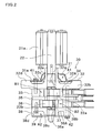
- Fig. 2 is a cross section of the drive mechanism and the compression mechanism of the rotary compressor of Fig. 1 .
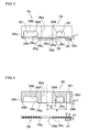
- Fig. 3 schematically shows a sealing structure.
- Fig. 4 schematically shows a rear head and a rear muffler before fastened.
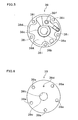
- Fig. 5 is a plan view of the rear head.
- Fig. 6 is a plan view of the rear muffler. Referring to Figs. 1 to 6 , details of a rotary compressor 1 of First Embodiment will be given.
- the rotary compressor 1 includes a closed casing 10 and this closed casing 10 houses therein a drive mechanism 20 and a compression mechanism 30.
- This rotary compressor 1 is a so-called high-pressure dome type compressor, and the compression mechanism 30 is disposed below the drive mechanism 20 in the closed casing 10.
- In the lower part of the closed casing 10 is stored lubricating oil 40 supplied to each slide portion of the compression mechanism 30.
- the drive mechanism 20 is provided to drive the compression mechanism 30 and includes a motor 21 as a drive source and a shaft 22 attached to the motor 21.
- the motor 21 includes a rotor 21a and a stator 21b which is provided radially outside the rotor 21a with an air gap therebetween.
- This rotor 21a has a rotatable shaft 22.
- the rotor 21a further has a rotor main body made of laminated magnetic steel sheets and a magnet embedded in the rotor main body.
- the stator 21b includes a stator main body made of steel and a coil wound around the stator main body. The motor 21 rotates the rotor 21a along with the shaft 22 by an electromagnetic power which is generated on the stator 21b in response to a current supply to the coil.
- the shaft 22 rotates along with the rotor 21a, rollers 34 and 37 of the compression mechanism 30 are rotated.
- the shaft 22 is provided with an eccentric portion 22a to be positioned in a cylinder chamber B1 of a later-described front cylinder 33, and is also provided with an eccentric portion 22b to be positioned in a cylinder chamber B2 of a rear cylinder 36.
- These eccentric portions 22a and 22b are provided with the rollers 34 and 37, respectively. Therefore, in response to the rotation of the shaft 22, the roller 34 attached to the eccentric portion 22a rotates in the cylinder chamber B1 and the roller 37 attached to the eccentric portion 22b rotates in the cylinder chamber B2.
- the eccentric portion 22a and the eccentric portion 22b deviate from each other by 180 degrees, in the direction of rotation of the shaft 22.
- the compression mechanism 30 is provided to compress and discharge refrigerant sucked from the accumulator 2.
- the refrigerant discharged from the compression mechanism 30 passes through the air gap between the stator 21b and the rotor 21a of the drive mechanism 20, cools the drive mechanism 20, and is then discharged from a discharge pipe 11.
- This compression mechanism 30 has, from the top to the bottom along the rotational axis of the shaft 22 of the drive mechanism 20, a front muffler 31, a front head 32, a front cylinder 33 and a roller 34, a middle plate 35, a rear cylinder 36 and a roller 37, a rear head 38, and a rear muffler 39.
- the front muffler 31 forms a muffler space A1 with the front head 32 in order to reduce the noise associated with the discharge of refrigerant.
- This front muffler 31 is hat-shaped and attached to block off a recess 32A of the front head 32.
- a bolt 41 by which the front muffler 31 is fixed is screwed into a screw hole of the front cylinder 33 via a through hole of a flange portion 31a of the front muffler 31 and a through hole of the front head 32.
- the front head 32 is provided above the front cylinder 33 to block off the upper opening of the cylinder chamber B1 of the front cylinder 33.
- This front head 32 includes a disc-shaped main body 32b having a bearing hole 32a into which the shaft 22 is inserted, an annular boss portion 32c which protrudes upward from the main body 32b while circumscribing the bearing hole 32a, an annular side wall 32d which protrudes upward from the main body 32b while circumscribing the boss portion 32c, and an annular bearing portion 32e which protrudes upward from the boss portion 32c while circumscribing the bearing hole 32a in the boss portion 32c.
- the main body 32b is provided with an ejection port (not illustrated) which discharges refrigerant compressed by the rotation of the roller 34 in the cylinder chamber B1 of the front cylinder 33.
- the refrigerant discharged from the ejection port is discharged through a discharge hole (not illustrated) formed in the front muffler 31, via the aforesaid muffler space A1.
- the main body 32b also has a discharge valve (not illustrated) which opens and closes the outlet of the ejection port.
- the front cylinder 33 has the cylinder chamber B1 having the roller 34 which eccentrically moves in response to the rotation of the shaft 22.
- This cylinder chamber B1 is connected to the muffler space A1 via the above-described unillustrated ejection port. Therefore, the refrigerant compressed by the eccentric movement of the roller 34 attached to the eccentric portion 22a of the shaft 22 is introduced from the cylinder chamber B1 into the muffler space A1 via the above-described ejection port.
- the middle plate 35 is provided between the front cylinder 33 and the rear cylinder 36. This middle plate 35 blocks off the lower opening of the cylinder chamber B1 of the front cylinder 33 and also blocks off the upper opening of the cylinder chamber B2 of the rear cylinder 36.
- the rear cylinder 36 is provided with the cylinder chamber B2 having the roller 37 which eccentrically moves in response to the rotation of the shaft 22.
- This cylinder chamber B2 is connected to the muffler space A2 via a later-described ejection port 38f (see Fig. 5 ). Therefore, the refrigerant compressed by the eccentric movement of the roller 37 attached to the eccentric portion 22b of the shaft 22 is introduced from the cylinder chamber B2 to the muffler space A2 via the ejection port 38f.
- the rear head 38 is provided below the rear cylinder 36 to block off the lower opening of the cylinder chamber B2 of the rear cylinder 36.
- this rear head 38 includes a disc-shaped main body 38b having a bearing hole 38a into which the shaft 22 is inserted, an annular boss portion 38c which protrudes downward from the main body 38b while circumscribing the bearing hole 38a, and an annular side wall 38d which protrudes downward from the main body 38b while circumscribing the boss portion 38c.
- the main body 38b has an ejection port 38f (see Fig. 5 ) which discharges refrigerant compressed by the rotation of the roller 37 in the cylinder chamber B2 of the rear cylinder 36.
- the refrigerant discharged from the ejection port 38f is discharged through a discharge hole 39d (see Fig. 6 ) formed in the rear muffler 39, via a later-described muffler space A2.
- the main body 38b is also provided with a discharge valve (not illustrated) by which the outlet of the ejection port 38f is opened and closed.
- the entirety of the end surface 38g of the boss portion 38c is below the plane including the end surface 38h of the side wall 38d, i.e. is further from the main body 38b than the plane including the end surface 38h.
- the side wall 38d has plural (five in the present embodiment) fastening holes 38i which allow the bolts 42 to penetrate therethrough, as shown in Fig. 5 .
- the rear head 38 is formed by sintering.
- the boss portion 38c and the side wall 38d are arranged so that the value P represented by the following relation (1) is 0.02 square millimeters or lower.
- P t ⁇ 3 ⁇ L ⁇ 1 / ⁇ ⁇ a ⁇ 2
- L1 level difference (mm) between boss portion 38c and side wall 38d in rear head 38 a: distance (mm) between axial center of rear head 38 and a part of inner periphery of fastening hole 38i of side wall 38d which part is closest to axial center of rear head 38
- b distance (mm) between axial center of rear head 38 and outer periphery of boss portion 38c ⁇ : flexibility factor with respect to diameter ratio b/a
- the relation (1) above derives from an equation (A) which is disclosed in " Mechanical Engineers' Handbook, Fundamentals, A4, Materials and Mechanics", The Japan Society of Mechanical Engineers, June 25, 1984, p55, No.
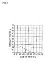
- the flexibility factor ⁇ with respect to the diameter ratio b/a is determined in accordance with the ratio of the distance a to the distance b, and is determined by the graph in Fig.
- the rear muffler 39 forms the muffler space A2 with the rear head 38 in order to reduce the noise associated with the discharge of refrigerant.
- This rear muffler 39 has a substantially flat shape and is attached to block off a recess 38A of the rear head 38.
- This rear muffler 39 has, as shown in Fig. 6 , five through holes 39a formed to positionally correspond to the above-described five fastening holes 38i (see Fig. 5 ) of the rear head 38, an opening 39b into which the shaft 22 is inserted, a peripheral portion 39c around the opening 39b, and a discharge hole 39d through which compressed refrigerant is discharged from the muffler space A2.
- the rear muffler 39 is made of a ferrous material.
- the above-described sealing structure 50 between the rear head 38 and the rear muffler 39 is formed in such a way that the rear muffler 39 is attached to the rear head 38. More specifically, five bolts 42 are screwed into the screw holes of the front cylinder 33 via the five through holes 39a made through the rear muffler 39, the five fastening holes 38i made through the rear head 38, and the five through holes made through the middle plate 35, so that the rear muffler 39 is fixed to the rear head 38. As a result, the peripheral portion 39c of the opening 39b of the rear muffler 39 contacts the end surface 38g of the boss portion 38c of the rear head 38.
- the substantially flat rear muffler 39 flexes as the peripheral portion 39c thereof contacts the end surface 38g of the boss portion 38c.
- the boss portion 38c of the rear head 38 tightly contacts the peripheral portion 39c of the rear muffler 39.
- the sealing structure 50 of First Embodiment has the following characteristics.
- the contact force of the peripheral portion 39c of the opening 39b of the rear muffler 39 onto the end surface 38g of the boss portion 38c is high, with the result that the sealing performance between the peripheral portion 39c of the rear muffler 39 and the boss portion 38c of the rear head 38 is secured.
- the sealing structure 50 can secure the sealing performance between the peripheral portion 39c of the rear muffler 39 and the boss portion 38c of the rear head 38 by the aforesaid flexing force, even if the mounting surface of the rear head 38 and the mounting surface of the rear muffler 39 are not precisely processed by machining. Since the process of machining of the rear head 38 and the rear muffler 39 is unnecessary, cost increase associated with the machining does not occur.
- the sealing structure 50 secures the sealing performance between the peripheral portion 39c of the rear muffler 39 and the boss portion 38c of the rear head 38 by the boss portion 38c of the rear head 38, an additional component (e.g. a conical claw washer of Patent Document 1) for improving the sealing performance of that part is unnecessary, and hence the productivity is improved.
- an additional component e.g. a conical claw washer of Patent Document 1 for improving the sealing performance of that part is unnecessary, and hence the productivity is improved.
- the sealing structure 50 can be formed by sintering because it is unnecessary to precisely process the rear head 38 by machining, and hence the productivity is improved.
- Fig. 8 schematically shows a sealing structure of a rotary compressor of Second Embodiment according to the present invention.
- Fig. 9 schematically shows a rear head and a rear muffler before fastened.
- Second Embodiment is different from First Embodiment in which the entirety of the end surface of the boss portion of the rear head is arranged to be further from the main body than the plane including the end surface of the side wall.
- Second Embodiment is arranged so that the peripheral portion of the opening of the rear muffler is shaped to protrude from a part contacting the end surface of the side wall. Since Second Embodiment is identical with First Embodiment except the arrangement of the rear head and the rear muffler, the same reference numerals are assigned to components having substantially identical arrangements as those of First Embodiment, and such components are not detailed again.
- a rear head 138 is provided below the rear cylinder 36 to block off the lower opening of the cylinder chamber B2 of the rear cylinder 36.
- this rear head 138 includes: a disc-shaped main body 138b having a bearing hole 138a into which the shaft 22 is inserted; an annular boss portion 138 which protrudes downward from the main body 138b while circumscribing the bearing hole 138a; and an annular side wall 138d which protrudes downward from the main body 138b while circumscribing the boss portion 138c.
- the main body 138b is provided with an ejection port (not illustrated) which discharges refrigerant compressed by the rotation of the roller 37 in the cylinder chamber B2 of the rear cylinder 36.
- the refrigerant discharged from the ejection port is discharged through a discharge hole (not illustrated) made through the rear muffler 139, via the muffler space A2.
- the main body 138b also has a discharge valve (not illustrated) by which the outlet of the ejection port is opened and closed.
- the end surface 138g of the boss portion 138c and the end surface 138h of the side wall 138d which have been described above are on the same plane.
- the side wall 138d further has plural fastening holes 138i (see Fig. 9 ) which allow bolts 42 to penetrate therethrough.
- the rear head 138 is formed by sintering.
- the boss portion 138c and the side wall 138d are arranged so that the value P represented by the relation (2) below is 0.02 square millimeters or lower.
- P thickness (mm) of rear muffler 139 L2: level difference (mm) between peripheral portion 139c of rear muffler 139 and a part of rear muffler 139 which part contacts end surface 138h of side wall 138d of rear head 138 a: distance (mm) between axial center of rear head 138 and a part of inner periphery of fastening hole 138i of side wall 138d which part is closest to axial center of rear head 138 b: distance (mm) between axial center of rear head 138 and outer periphery of boss portion 138c ⁇ : flexibility factor with respect to diameter ratio b/a
- the relation (2) also derives from the above-described equation (A).
- the flexibility factor ⁇ with respect to the diameter ratio b/a is determined according to the ratio between the aforesaid distances and b, and is determined by the graph in Fig. 7 .
- the rear muffler 139 forms the muffler space A2 with the rear head 138 in order to reduce noise associated with the discharge of refrigerant.
- This rear muffler 139 is attached to block off a recess 138A of the rear head 138.
- the rear muffler 139 has five through holes (not illustrated) positionally corresponding to the fastening holes 138i of the rear head 138, an opening 139b into which the shaft 22 is inserted, a peripheral portion 139c around the opening 139b, and a discharge hole (not illustrated) through which compressed refrigerant is discharged from the muffler space A2.
- the peripheral portion 139c of the rear muffler 139 before being fastened to rear head 138 is arranged to protrude from a part which contacts the end surface 138h of the side wall 138d of the rear head 138.
- the rear muffler 139 is made of a ferrous material.
- the above-described sealing structure 150 between the rear head 138 and the rear muffler 139 is formed in such a way that the rear muffler 139 is attached to the rear head 138. More specifically, five bolts 42 are screwed into the screw holes of the front cylinder 33 via the five through holes made through the rear muffler 139, the five fastening holes 138i made through the rear head 138, and the five through holes made through the middle plate 35, so that the rear muffler 139 is fixed to the rear head 138. As a result, the peripheral portion 139c of the opening 139b of the rear muffler 139 contacts the end surface 138g of the boss portion 138c of the rear head 138.
- the rear muffler 139 flexes as the peripheral portion 139c thereof contacts the end surface of the boss portion 138c.
- the boss portion 138c of the rear head 138 tightly contacts the peripheral portion 139c of the rear muffler 139.
- the distance a between the axial center of the rear head and a part of the inner periphery of the fastening hole of the side wall which part is closest to the axial center of the rear head was set to 28mm
- the distance b between the axial center of the rear head and the outer periphery of the boss portion was set to 13mm
- the flexibility factor ⁇ with respect to the diameter ratio b/a was set to 0.1.
- Table 1 above shows that the rotary compressor can operate without the occurrence of locking, when the value P is not higher than 0.02 square millimeters. This seems because a load sufficient to distort the rear head (boss portion) is not applied to the rear head (boss portion) when the value P is not higher than 0.02 square millimeters and hence the distortion of the rear head is restrained.
- the embodiments above describe the sealing structure between the rear head and the rear muffler which are on the rear side.
- the present invention is not limited to this arrangement and is applicable to the sealing structure between the front head and the front muffler on the front side.
- the embodiments above describe the case where the sealing structure between the rear head and the rear muffler is used for the rotary compressor.
- the present invention is not limited to this and may be applicable to various compressors such as a scroll compressor.
- First Embodiment above describes the case where the end surface 38g of the boss portion 38c of the rear head 38 is a horizontal surface.
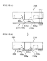
- the present invention is not limited to this arrangement and may be arranged so that, as in the case of a sealing structure 250 of a variation of First Embodiment shown in Fig. 10 , an end surface 238g of a boss portion 238c of a rear head 238 is tapered radially inward.
- a peripheral portion 239c of a rear muffler 239 surface-contacts the end surface 238g of the boss portion 238c of the rear head 238, and hence the sealing performance between the peripheral portion 239c and the boss portion 238c is further improved.
- the protruding peripheral portion 139c of the rear muffler 139 is a horizontal surface.
- the present invention is not limited to this arrangement and may be arranged so that, as in a variation of Second Embodiment show in Fig. 11 , a protruding peripheral portion 339c of a rear muffler 339 is tapered radially inward.
- a peripheral portion 339c of a rear muffler 339 surface-contacts a boss portion 338c of a rear head 338, and hence the sealing performance between the peripheral portion 339c and the boss portion 338c is further improved.
- First Embodiment describes the case where the annular bearing portion 32e protruding upward from the boss portion 32c is provided so as to circumscribe the bearing hole 32a in the boss portion 32c of the front head 32.
- the present invention may be arranged so that, as in a variation of First Embodiment shown in Fig. 12 , a rear head 438 is provided with an annular bearing portion 438e protruding downward from a boss portion 438c so as to circumscribe a bearing hole 438a in a boss portion 438c of a rear head 438, in the manner similar to the bearing portion 32e (see Fig. 2 ) of the front head 32 of First Embodiment.
- the bearing length of the shaft is long.
- First Embodiment above describes the case where the entirety of the end surface 38g of the boss portion 38c of the rear head 38 is arranged to be further from the main body 38b than the plane including the end surface 38h of the side wall 38d.
- Second Embodiment above describes the case where the peripheral portion 139c of the opening 139b of the rear muffler 139 is arranged to protrude from the part contacting the end surface 138h of the side wall 138d.
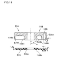
- the present invention is not limited to these arrangements, and may be arranged, as shown in Fig. 13 , to be a sealing structure 550 in which the boss portion of the rear head of First Embodiment is combined with the peripheral portion of the rear muffler of Second Embodiment.
- a boss portion 538c and a side wall 538d are preferably arranged so that the value P in the relation (3) below is not higher than 0.02 square millimeters.
- P t ⁇ 3 ⁇ L ⁇ 1 + L ⁇ 2 / ⁇ ⁇ a ⁇ 2
- t thickness (mm) of rear muffler 539
- L1 level difference (mm) between boss portion 538c and side wall 538d in rear head 538
- L2 level difference (mm) between peripheral portion 539c of rear muffler 539 and a part of rear muffler 539 which part contacts end surface 538h of side wall 538d of rear head 538 a: distance (mm) between axial center of rear head 538 and a part of inner periphery of fastening hole 538i of side wall 538d which part is closest to axial center of rear head 538 b: distance (mm) between axial center of rear head 538 and outer periphery of boss portion 538c
- the present invention makes it possible to secure the sealing performance between the head component and the muffler component without precisely processing the mounting surfaces of the head component and the muffler component and without increasing the number of components.
Landscapes
- Engineering & Computer Science (AREA)
- Mechanical Engineering (AREA)
- General Engineering & Computer Science (AREA)
- Compressor (AREA)
- Applications Or Details Of Rotary Compressors (AREA)
Abstract
Description
- The present invention relates to a sealing structure between a head component having an ejection port ejecting compressed refrigerant and a muffler component which is provided so that a muffler space is formed between the head component and the muffler component, and also relates to a compressor having the sealing structure.
- A typical rotary compressor includes a cylinder, a roller which rotates in a cylinder chamber of the cylinder, a head component having an ejection port by which refrigerant compressed by the rotation of the roller is ejected, and a muffler component which is provided so that a muffler space is formed between the head component and the muffler component.
Fig. 14 schematically illustrates a sealing structure between a head component and a muffler component according to a conventional example. As shown inFig. 14(a) , aconventional sealing structure 650 between a head component and a muffler component is arranged so that themuffler component 639 is fastened to aside wall 638d of thehead component 638 byplural bolts 642, and a muffler space is formed by blocking off arecess 638A formed in thehead component 638. - However, the
conventional sealing structure 650 ofFig. 14(a) is disadvantageous in that, when a mounting surface of themuffler component 639 and a mounting surface of thehead component 638 are not flat enough, a gap is formed between aboss portion 638c of thehead component 638 and themuffler component 639 as shown inFig. 14(b) , and refrigerant leaks out from the gap. - In consideration of the above, recent developed arrangements prevent the leakage of refrigerant through the gap by preventing the formation of the gap between the boss portion and the muffler component in such a way that the precision of the mounting surfaces of the muffler component and the head component is improved by machining.
- However, even if the mounting surfaces of the muffler component and the head component have been subjected to machining, as shown in
Fig. 14(c) , refrigerant introduced through an ejection port (not illustrated) of thehead component 638 causes a pressure P1 of the muffler space to be higher than a pressure P2 in the closed container of the compressor, with the result that the refrigerant leaks out from the border between theboss portion 638c and themuffler component 639, which part is not fastened by thebolts 642. The leakage of refrigerant induces increase in vibration and noise of the compressor and obstructs lubricating oil from being supplied to a slide portion because the lubricating oil stored in the bottom portion of the closed container foams, and hence the reliability of the compressor is deteriorated. - To solve this problem, various structures have been proposed to prevent refrigerant from leaking from the border between the boss portion and the muffler component (see e.g. Patent Document 1). A rotary compressor disclosed in Patent Document 1 is arranged so that the leakage of refrigerant from the border between the boss portion and the muffler component is prevented by providing a conical claw washer as a gas sealing member between the boss portion and the muffler component.
-
- [Patent Document 1] Japanese Unexamined Patent Publication No.
215993/1990 - The rotary compressor of Patent Document 1, however, is disadvantageous in that it is necessary to increase the number of components because a conical claw washer is required to secure the sealing performance between the boss portion and the muffler component.
- The present invention was done to solve the problem above, and an objective of the present invention is to provide a sealing structure and a compressor, which are capable of securing the sealing performance between the head component and the muffler component without increasing the machining accuracy of the mounting surfaces of the head component and the muffler component and without increasing the number of components.
- A sealing structure according to the first aspect of the invention is between a head component having an ejection port ejecting compressed refrigerant and a muffler component which is disposed so that a muffler space is formed between the muffler component and the head component, wherein, the head component includes: a main body having a bearing hole into which an axial member is inserted; an annular boss portion protruding from the main body while circumscribing the bearing hole; and an annular side wall protruding from the main body while circumscribing the boss portion, and wherein, the muffler component has an opening into which the axial member is inserted and the muffler component is fastened to an end surface of the side wall so that a peripheral portion of the opening contacts an end surface of the boss portion, and wherein, the end surface of the boss portion has a part which is entirely further from the main body than the end surface of the side wall.
- In this sealing structure, since the end surface of the boss portion is further from the main body than the plane including the end surface of the side wall, the contact force of the peripheral portion of the opening of the muffler component onto the end surface of the boss portion is high, with the result that the sealing performance between the peripheral portion of the muffler component and the boss portion of the head component is secured. This prevents the formation of a gap between the peripheral portion of the muffler component and the boss portion of the head component, thereby preventing refrigerant from leaking from the gap. Consequently, in a compressor having the sealing structure above, problems such as vibration and noise of the compressor and the foaming of the lubricating oil caused by leaked refrigerant are restrained, and hence the deterioration of the reliability of the compressor is restrained.
- In addition to the above, the sealing structure can secure the sealing performance between the peripheral portion of the muffler component and the boss portion of the head component by the aforesaid contact force, even if the mounting surface of the head component and the mounting surface of the muffler component are not precisely processed by machining. Since the process of machining of the head component and the muffler component is unnecessary, cost increase associated with the machining does not occur.
- In addition to the above, since the sealing structure secures the sealing performance between the peripheral portion of the muffler component and the boss portion of the head component by the boss portion of the head component, an additional component for improving the sealing performance of that part is unnecessary, and hence the productivity is improved.
- In the second aspect of the invention, the sealing structure according to the first aspect of the invention is further arranged so that the end surface of the boss portion is entirely further from the main body than the plane including the end surface of the side wall.
- In this sealing structure, the entirety of the end surface of the boss portion contacting the peripheral portion of the opening of the muffler component is further from the main body than the plane including the end surface of the side wall, and hence the sealing performance between the peripheral portion of the muffler component and the boss portion of the head component is further improved.
- In the third aspect of the invention, the sealing structure according to the first or second aspect is further arranged so that the end surface of the boss portion is arranged to taper radially inward.
- In this sealing structure, the end surface of the boss portion can be arranged to taper in accordance with the shape of the peripheral portion of the muffler component, which flexes and deforms due to the contact with the boss portion. As a result, the peripheral portion of the muffler component surface-contacts the boss portion of the head component, and hence the sealing performance between the peripheral portion of the muffler component and the boss portion of the head component is further improved.
- In addition to the above, in this sealing structure, since the direction of the force exerted from the muffler component to the end surface of the boss portion is oblique to the axial direction of the boss portion, it is possible to restrain the distortion of the head component.
- In the fourth aspect of the invention, the sealing structure according to any one of the first to third aspects is further arranged so that, on a fastening plane of the muffler component before the muffler component is fastened to the head component, the peripheral portion of the opening is arranged to protrude from a part of the fastening plane which part contacts the end surface of the side wall.
- In this sealing structure, the protruding peripheral portion contacts the above-described boss portion. Therefore the contact force of the peripheral portion onto the end surface of the boss portion is further enhanced, and hence the sealing performance between the peripheral portion of the muffler component and the boss portion of the head component is further improved.
- In the fifth aspect of the invention, the sealing structure according to any one of the first to third aspects is further arrangement so that, the muffler component is made of a ferrous material, the head component has plural fastening holes penetrating the side wall, and the boss portion and the side wall are arranged so that a value P calculated from a relation P=(t3×L1)/(α×a2) is 0.02 square millimeters or lower, where,
t is a thickness of the muffler component,
L1 is a level difference between the boss portion and the side wall in the head component,
a is a distance between an axial center of the head component and a part of an inner periphery of one of the fastening holes of the side wall which part is closest to the axial center of the head component,
b is a distance between the axial center of the head component and an outer periphery of the boss portion, and
α is a flexibility factor with respect to a diameter ratio b/a. - The inventors of the present invention have found that a load sufficient to distort the head component is not applied to the boss portion and the distortion of the head component is restrained when the value P represented by the relation above is 0.02 square millimeters or lower. Furthermore, the inventors have also found that, when the sealing structure above is used in a compressor, the occurrence of locking in the compressor due to the distortion of the head component is restrained.
- A sealing structure of the sixth aspect of the invention is between a head component having an ejection port ejecting compressed refrigerant and a muffler component which is disposed so that a muffler space is formed between the muffler component and the head component, wherein, the head component includes: a main body having a bearing hole into which an axial member is inserted; an annular boss portion protruding from the main body while circumscribing the bearing hole; and an annular side wall protruding from the main body while circumscribing the boss portion, and wherein, the muffler component has an opening into which the axial member is inserted and the muffler component is fastened to an end surface of the side wall so that a peripheral portion of the opening contacts an end surface of the boss portion, and wherein, on a fastening plane of the muffler component before the muffler component is fastened to the head component, the peripheral portion is arranged to protrude from a part of the fastening plane which part contacts the end surface of the side wall.
- In this sealing structure, since the peripheral portion of the muffler component protrudes from the part contacting the end surface of the side wall, the contact force of the peripheral portion of the opening of the muffler component onto the end surface of the boss portion is high, with the result that the sealing performance between the peripheral portion of the muffler component and the boss portion of the head component is secured. This prevents the formation of a gap between the peripheral portion of the muffler component and the boss portion of the head component, thereby preventing refrigerant from leaking from the gap. Consequently, in a compressor having the sealing structure above, problems such as vibration and noise of the compressor and the foaming of the lubricating oil caused by leaked refrigerant are restrained, and hence the deterioration of the reliability of the compressor is restrained.
- In addition to the above, the sealing structure can secure the sealing performance between the peripheral portion of the muffler component and the boss portion of the head component by the aforesaid contact force, even if the mounting surface of the head component and the mounting surface of the muffler component are not precisely processed by machining. Since the process of machining of the head component and the muffler component is unnecessary, cost increase associated with the machining does not occur.
- In addition to the above, since the sealing structure secures the sealing performance between the peripheral portion of the muffler component and the boss portion of the head component by the peripheral portion of the muffler component, an additional component for improving the sealing performance of that part is unnecessary, and hence the productivity is improved.
- In the seventh aspect of the invention, the sealing structure according to the sixth aspect is further arranged so that the peripheral portion is arranged to taper radially inward.
- In this sealing structure, the peripheral portion of the muffler component can be arranged to taper so that the peripheral portion flexing and deforming due to the contact with the boss portion is shaped in accordance with the end surface of the boss portion. As a result, the peripheral portion of the muffler component surface-contacts the boss portion of the head component, and hence the sealing performance between the peripheral portion of the muffler component and the boss portion of the head component is further improved.
- In the eighth aspect of the invention, the sealing structure according to the sixth or seventh aspect is further arranged so that the end surface of the boss portion and the end surface of the side wall are on a single plane.
- In the ninth aspect of the invention, the sealing structure according to the sixth or seventh aspect is further arranged so that the end surface of the boss portion has a part which is entirely further from the main body than a plane including the end surface of the side wall.
- In this sealing structure, the protruding peripheral portion contacts the boss portion having the end surface which is further from the main body than the plane including the end surface of the side wall. Therefore the contact force of the peripheral portion onto the end surface of the boss portion is further enhanced, and hence the sealing performance between the peripheral portion of the muffler component and the boss portion of the head component is further improved.
- In the tenth aspect of the invention, the sealing structure according to the ninth aspect is further arrangement so that the end surface of the boss portion is entirely further from the main body than the plane including the end surface of the side wall.
- In this sealing structure, since the entirety of the end surface of the boss portion contacting the peripheral portion of the opening of the muffler component is further from the main body than the end surface of the side wall, the sealing performance between the peripheral portion of the muffler component and the boss portion of the head component is further improved.
- In the eleventh aspect of the invention, the sealing structure according to any one of the sixth to eighth aspects is further arranged so that the muffler component is made of a ferrous material, the head component has plural fastening holes penetrating the side wall, and the boss portion and the side wall are arranged so that a value P calculated from a relation P=(t3×L2) / (α×a2) is 0.02 square millimeters or lower, where,
t is a thickness of the muffler component,
L2 is a level difference between a peripheral portion of the muffler component and a part of the muffler component which part contacts the end surface of the side wall of the head component,
a is a distance between an axial center of the head component and a part of an inner periphery of one of the fastening holes of the side wall which part is closest to the axial center of the head component,
b is a distance between the axial center of the head component and an outer periphery of the boss portion, and
α is a flexibility factor with respect to a diameter ratio b/a. - The inventors of the present invention have found that a load sufficient to distort the head component is not applied to the boss portion and the distortion of the head component is restrained when the value P represented by the relation above is 0.02 square millimeters or lower. Furthermore, the inventors have also found that, when the sealing structure above is used in a compressor, the occurrence of locking in the compressor due to the distortion of the head component (boss portion) is restrained.
- In the twelfth aspect of the invention, the sealing structure according to any one of the fourth, ninth, and tenth aspects is further arranged so that, the muffler component is made of a ferrous material, the head component has plural fastening holes penetrating the side wall, and the boss portion and the side wall are arranged so that a value P calculated from a relation P=(t3×(L1+L2))/(α×a2) is 0.02 square millimeters or lower, where,
t is a thickness of the muffler component,
L1 is a level difference between the boss portion and the side wall in the head component,
L2 is a level difference between a peripheral portion of the muffler component and a part of the muffler component which part contacts the end surface of the side wall of the head component,
a is a distance between an axial center of the head component and a part of an inner periphery of one of the fastening holes of the side wall which part is closest to the axial center of the head component,
b is a distance between the axial center of the head component and an outer periphery of the boss portion, and α is a flexibility factor with respect to a diameter ratio b/a. - The inventors of the present invention have found that a load sufficient to distort the head component is not applied to the boss portion and the distortion of the head component is restrained when the value P represented by the relation above is 0.02 square millimeters or lower. Furthermore, the inventors have also found that, when the sealing structure above is used in a compressor, the occurrence of locking in the compressor due to the distortion of the head component (boss portion) is restrained.
- In the thirteenth aspect of the invention, the sealing structure according to any one of the first to twelfth aspects is further arranged so that the head component has an annular bearing portion which protrudes from the boss portion while circumscribing the bearing hole in the boss portion.
- In this sealing structure, the bearing length of the axial member is long.
- In the fourteenth aspect of the invention, the sealing structure according to any one of the first to thirteenth aspects is further arranged so that the head component is formed by sintering.
- This sealing structure can be formed by sintering because it is unnecessary to precisely process the head component by machining, and hence the productivity is improved.
- A compressor according to the fifteenth aspect of the invention includes the sealing structure according to any one of the first to fourteenth aspects.
- As described above, this compressor makes it possible to secure the sealing performance between the head component and the muffler component without precisely processing the mounting surfaces of the head component and the muffler component and without increasing the number of components.
- As described above, the present invention achieves the following effects.
- According to the first and second aspects of the invention, the contact force of the peripheral portion of the opening of the muffler component onto the end surface of the boss portion is high, with the result that the sealing performance between the peripheral portion of the muffler component and the boss portion of the head component is secured. Consequently, in a compressor having the sealing structure above, problems such as vibration and noise of the compressor and the foaming of the lubricating oil caused by leaked refrigerant are restrained, and hence the deterioration of the reliability of the compressor is restrained. Furthermore, since the process of machining of the mounting surface of the head component and the mounting surface of the muffler component is unnecessary, cost increase associated with the machining does not occur. Furthermore, an additional component for improving the sealing performance of that part is unnecessary, and hence the productivity is improved.
- According to the third aspect of the invention, the peripheral portion of the muffler component surface-contacts the boss portion of the head component, and hence the sealing performance between the peripheral portion of the muffler component and the boss portion of the head component is further improved. Furthermore, since the direction of the force exerted from the muffler component to the end surface of the boss portion is oblique to the axial direction of the boss portion, it is possible to restrain the distortion of the head component.
- According to the fourth aspect of the invention, the protruding peripheral portion contacts the above-described boss portion. Therefore the contact force of the peripheral portion onto the end surface of the boss portion is further enhanced, and hence the sealing performance between the peripheral portion of the muffler component and the boss portion of the head component is further improved.
- According to the fifth, eleventh, and twelfth aspects of the invention, when the sealing structure above is used in a compressor, the occurrence of locking in the compressor due to the distortion of the head component (boss portion) is restrained.
- According to the sixth, ninth, and tenth aspects of the invention, the contact force of the peripheral portion of the muffler component onto the end surface of the boss portion is high, with the result that the sealing performance between the peripheral portion of the muffler component and the boss portion of the head component is secured. Consequently, in a compressor having the sealing structure above, problems such as vibration and noise of the compressor and the foaming of the lubricating oil caused by leaked refrigerant are restrained, and hence the deterioration of the reliability of the compressor is restrained. Furthermore, since the process of machining of the mounting surface of the head component and the mounting surface of the muffler component is unnecessary, cost increase associated with the machining does not occur. Furthermore, an additional component for improving the sealing performance of that part is unnecessary, and hence the productivity is improved.
- According to the seventh aspect of the invention, the peripheral portion of the muffler component surface-contacts the boss portion of the head component, and hence the sealing performance between the peripheral portion of the muffler component and the boss portion of the head component is further improved. Furthermore, since the direction of the force exerted from the muffler component to the end surface of the boss portion is oblique to the axial direction of the boss portion, it is possible to restrain the distortion of the head component.
- According to the thirteenth aspect of the invention, the bearing length of the axial member is long.
- According to the fourteenth aspect of the invention, the sealing structure can be formed by sintering because it is unnecessary to precisely process the head component by machining, and hence the productivity is improved.
- According to the fifteenth aspect of the invention, it is possible to secure the sealing performance between the head component and the muffler component without precisely processing the mounting surfaces of the head component and the muffler component and without increasing the number of components.
-
-
Fig. 1 is a cross section of a rotary compressor and an accumulator of First Embodiment according to present invention. -
Fig. 2 is a cross section of the drive mechanism and the compression mechanism of the rotary compressor ofFig. 1 . -
Fig. 3 schematically shows a sealing structure. -
Fig. 4 schematically shows a rear head and a rear muffler before fastened. -
Fig. 5 is a plan view of the rear head. -
Fig. 6 is a plan view of the rear muffler. -
Fig. 7 is a graph showing a flexibility factor α with respect to a diameter ratio b/a. -
Fig. 8 schematically shows a sealing structure of a rotary compressor of Second Embodiment according to the present invention. -
Fig. 9 schematically shows a rear head and a rear muffler before fastened. -
Fig. 10 schematically shows a sealing structure of a variation of First Embodiment. -
Fig. 11 schematically shows a sealing structure of a variation of Second Embodiment. -
Fig. 12 schematically shows a sealing structure of a variation of First Embodiment. -
Fig. 13 schematically shows a sealing structure in which the rear head of First Embodiment is combined with the rear muffler of Second Embodiment. -
Fig. 14 schematically shows a conventional sealing structure between a head component and a muffler component. -
- 1
- ROTARY COMPRESSOR
- 38,138, 238, 338, 438, 538
- REAR HEAD (HEAD COMPONENT)
- 38a, 138a, 438a
- BEARING HOLE
- 38b, 138b
- MAIN BODY
- 38c, 138c, 238c, 338c, 438c, 538c
- BOSS PORTION
- 38d, 138d, 538d
- SIDE WALL
- 38f
- EJECTION PORT
- 38g, 138g, 238g, 338g
- END SURFACE OF BOSS PORTION
- 38h, 138h, 538h
- END SURFACE OF SIDE WALL
- 39, 139, 239, 339, 539
- REAR MUFFLER (MUFFLER COMPONENT)
- 39b,139b
- OPENING
- 39c, 139c, 239c, 339c, 539c
- PERIPHERAL PORTION
- 50, 150, 250, 350, 450, 550
- SEALING STRUCTURE
- A2
- MUFFLER SPACE
- The following will describe an embodiment of a compressor having a sealing structure of the present invention with reference to figures.
-
Fig. 1 is a cross section of a rotary compressor and an accumulator of First Embodiment according to present invention.Fig. 2 is a cross section of the drive mechanism and the compression mechanism of the rotary compressor ofFig. 1 .Fig. 3 schematically shows a sealing structure.Fig. 4 schematically shows a rear head and a rear muffler before fastened.Fig. 5 is a plan view of the rear head.Fig. 6 is a plan view of the rear muffler. Referring toFigs. 1 to 6 , details of a rotary compressor 1 of First Embodiment will be given. - As shown in
Fig. 1 andFig. 2 , the rotary compressor 1 includes aclosed casing 10 and this closed casing 10 houses therein adrive mechanism 20 and acompression mechanism 30. This rotary compressor 1 is a so-called high-pressure dome type compressor, and thecompression mechanism 30 is disposed below thedrive mechanism 20 in theclosed casing 10. In the lower part of theclosed casing 10 is stored lubricatingoil 40 supplied to each slide portion of thecompression mechanism 30. - The
drive mechanism 20 is provided to drive thecompression mechanism 30 and includes amotor 21 as a drive source and ashaft 22 attached to themotor 21. - The
motor 21 includes arotor 21a and astator 21b which is provided radially outside therotor 21a with an air gap therebetween. Thisrotor 21a has arotatable shaft 22. Therotor 21a further has a rotor main body made of laminated magnetic steel sheets and a magnet embedded in the rotor main body. Thestator 21b includes a stator main body made of steel and a coil wound around the stator main body. Themotor 21 rotates therotor 21a along with theshaft 22 by an electromagnetic power which is generated on thestator 21b in response to a current supply to the coil. - As the
shaft 22 rotates along with therotor 21a,rollers compression mechanism 30 are rotated. Theshaft 22 is provided with aneccentric portion 22a to be positioned in a cylinder chamber B1 of a later-describedfront cylinder 33, and is also provided with aneccentric portion 22b to be positioned in a cylinder chamber B2 of arear cylinder 36. Theseeccentric portions rollers shaft 22, theroller 34 attached to theeccentric portion 22a rotates in the cylinder chamber B1 and theroller 37 attached to theeccentric portion 22b rotates in the cylinder chamber B2. Theeccentric portion 22a and theeccentric portion 22b deviate from each other by 180 degrees, in the direction of rotation of theshaft 22. - On the other hand, the
compression mechanism 30 is provided to compress and discharge refrigerant sucked from theaccumulator 2. The refrigerant discharged from thecompression mechanism 30 passes through the air gap between thestator 21b and therotor 21a of thedrive mechanism 20, cools thedrive mechanism 20, and is then discharged from adischarge pipe 11. Thiscompression mechanism 30 has, from the top to the bottom along the rotational axis of theshaft 22 of thedrive mechanism 20, afront muffler 31, afront head 32, afront cylinder 33 and aroller 34, amiddle plate 35, arear cylinder 36 and aroller 37, arear head 38, and arear muffler 39. - The
front muffler 31 forms a muffler space A1 with thefront head 32 in order to reduce the noise associated with the discharge of refrigerant. Thisfront muffler 31 is hat-shaped and attached to block off arecess 32A of thefront head 32. Abolt 41 by which thefront muffler 31 is fixed is screwed into a screw hole of thefront cylinder 33 via a through hole of aflange portion 31a of thefront muffler 31 and a through hole of thefront head 32. - The
front head 32 is provided above thefront cylinder 33 to block off the upper opening of the cylinder chamber B1 of thefront cylinder 33. Thisfront head 32 includes a disc-shapedmain body 32b having abearing hole 32a into which theshaft 22 is inserted, anannular boss portion 32c which protrudes upward from themain body 32b while circumscribing thebearing hole 32a, anannular side wall 32d which protrudes upward from themain body 32b while circumscribing theboss portion 32c, and anannular bearing portion 32e which protrudes upward from theboss portion 32c while circumscribing thebearing hole 32a in theboss portion 32c. Themain body 32b is provided with an ejection port (not illustrated) which discharges refrigerant compressed by the rotation of theroller 34 in the cylinder chamber B1 of thefront cylinder 33. The refrigerant discharged from the ejection port is discharged through a discharge hole (not illustrated) formed in thefront muffler 31, via the aforesaid muffler space A1. Themain body 32b also has a discharge valve (not illustrated) which opens and closes the outlet of the ejection port. - The
front cylinder 33 has the cylinder chamber B1 having theroller 34 which eccentrically moves in response to the rotation of theshaft 22. This cylinder chamber B1 is connected to the muffler space A1 via the above-described unillustrated ejection port. Therefore, the refrigerant compressed by the eccentric movement of theroller 34 attached to theeccentric portion 22a of theshaft 22 is introduced from the cylinder chamber B1 into the muffler space A1 via the above-described ejection port. - The
middle plate 35 is provided between thefront cylinder 33 and therear cylinder 36. Thismiddle plate 35 blocks off the lower opening of the cylinder chamber B1 of thefront cylinder 33 and also blocks off the upper opening of the cylinder chamber B2 of therear cylinder 36. - The
rear cylinder 36 is provided with the cylinder chamber B2 having theroller 37 which eccentrically moves in response to the rotation of theshaft 22. This cylinder chamber B2 is connected to the muffler space A2 via a later-describedejection port 38f (seeFig. 5 ). Therefore, the refrigerant compressed by the eccentric movement of theroller 37 attached to theeccentric portion 22b of theshaft 22 is introduced from the cylinder chamber B2 to the muffler space A2 via theejection port 38f. - The
rear head 38 is provided below therear cylinder 36 to block off the lower opening of the cylinder chamber B2 of therear cylinder 36. As shown inFig. 2 to Fig. 5 , thisrear head 38 includes a disc-shapedmain body 38b having abearing hole 38a into which theshaft 22 is inserted, anannular boss portion 38c which protrudes downward from themain body 38b while circumscribing thebearing hole 38a, and anannular side wall 38d which protrudes downward from themain body 38b while circumscribing theboss portion 38c. Themain body 38b has anejection port 38f (seeFig. 5 ) which discharges refrigerant compressed by the rotation of theroller 37 in the cylinder chamber B2 of therear cylinder 36. The refrigerant discharged from theejection port 38f is discharged through adischarge hole 39d (seeFig. 6 ) formed in therear muffler 39, via a later-described muffler space A2. Themain body 38b is also provided with a discharge valve (not illustrated) by which the outlet of theejection port 38f is opened and closed. In the present embodiment, as shown inFig. 3 and Fig. 4 , the entirety of theend surface 38g of theboss portion 38c is below the plane including theend surface 38h of theside wall 38d, i.e. is further from themain body 38b than the plane including theend surface 38h. Theside wall 38d has plural (five in the present embodiment)fastening holes 38i which allow thebolts 42 to penetrate therethrough, as shown inFig. 5 . Therear head 38 is formed by sintering. - In the present embodiment, furthermore, the
boss portion 38c and theside wall 38d are arranged so that the value P represented by the following relation (1) is 0.02 square millimeters or lower.
where, t: thickness of rear muffler 39 (mm)
L1: level difference (mm) betweenboss portion 38c andside wall 38d inrear head 38
a: distance (mm) between axial center ofrear head 38 and a part of inner periphery offastening hole 38i ofside wall 38d which part is closest to axial center ofrear head 38
b: distance (mm) between axial center ofrear head 38 and outer periphery ofboss portion 38c
α: flexibility factor with respect to diameter ratio b/a
The relation (1) above derives from an equation (A) which is disclosed in "Mechanical Engineers' Handbook, Fundamentals, A4, Materials and Mechanics", The Japan Society of Mechanical Engineers, June 25, 1984, p55, No. 10 and indicates a flexible volume w when a circle-shaped load is applied to the inner circumference of an annular disc while the outer circumference thereof is fixed.
where, α': flexibility factor
P': supporting load applied to inner periphery
E': Young's modulus of material of annular disc
t': thickness of annular disc
a': distance between center and fixed part of outer circumference - Regarding the relation (1), the thickness t of the
rear muffler 39, the level difference L1 between theboss portion 38c and theside wall 38d in therear head 38, the distance a between the axial center of therear head 38 and a part of the inner periphery of thefastening hole 38i of theside wall 38d which part is closest to the axial center of therear head 38, and the distance b between the axial center of therear head 38 and the outer periphery of theboss portion 38c are arranged as shown inFig. 3 and Fig. 4 . The flexibility factor α with respect to the diameter ratio b/a is determined in accordance with the ratio of the distance a to the distance b, and is determined by the graph inFig. 7 in the same manner as the flexibility factor α' in the equation (A). The graph is disclosed in "Mechanical Engineers' Handbook, Fundamentals, A4, Materials and Mechanics", The Japan Society of Mechanical Engineers, June 25, 1984, p58, Fig. 83. - The
rear muffler 39 forms the muffler space A2 with therear head 38 in order to reduce the noise associated with the discharge of refrigerant. Thisrear muffler 39 has a substantially flat shape and is attached to block off arecess 38A of therear head 38. Thisrear muffler 39 has, as shown inFig. 6 , five throughholes 39a formed to positionally correspond to the above-described fivefastening holes 38i (seeFig. 5 ) of therear head 38, anopening 39b into which theshaft 22 is inserted, aperipheral portion 39c around theopening 39b, and adischarge hole 39d through which compressed refrigerant is discharged from the muffler space A2. Therear muffler 39 is made of a ferrous material. - The above-described
sealing structure 50 between therear head 38 and therear muffler 39 is formed in such a way that therear muffler 39 is attached to therear head 38. More specifically, fivebolts 42 are screwed into the screw holes of thefront cylinder 33 via the five throughholes 39a made through therear muffler 39, the fivefastening holes 38i made through therear head 38, and the five through holes made through themiddle plate 35, so that therear muffler 39 is fixed to therear head 38. As a result, theperipheral portion 39c of theopening 39b of therear muffler 39 contacts theend surface 38g of theboss portion 38c of therear head 38. In this regard, since theend surface 38g of theboss portion 38c is below the plane including theend surface 38h of theside wall 38d, the substantially flatrear muffler 39 flexes as theperipheral portion 39c thereof contacts theend surface 38g of theboss portion 38c. By this flexing force of theperipheral portion 39c, theboss portion 38c of therear head 38 tightly contacts theperipheral portion 39c of therear muffler 39. - The sealing
structure 50 of First Embodiment has the following characteristics. - In the sealing
structure 50 of the present embodiment, as theend surface 38g is further from themain body 38b than the plane including theend surface 38h of theside wall 38d, the contact force of theperipheral portion 39c of theopening 39b of therear muffler 39 onto theend surface 38g of theboss portion 38c is high, with the result that the sealing performance between theperipheral portion 39c of therear muffler 39 and theboss portion 38c of therear head 38 is secured. This prevents the formation of a gap between theperipheral portion 39c of therear muffler 39 and theboss portion 38c of therear head 38, thereby preventing refrigerant from leaking from the gap. Consequently, in the rotary compressor 1 having the sealingstructure 50 above, problems such as vibration and noise of the rotary compressor 1 and the foaming of the lubricatingoil 40 caused by leaked refrigerant are restrained, and hence the deterioration of the reliability of the rotary compressor 1 is restrained. - In addition to the above, the sealing
structure 50 can secure the sealing performance between theperipheral portion 39c of therear muffler 39 and theboss portion 38c of therear head 38 by the aforesaid flexing force, even if the mounting surface of therear head 38 and the mounting surface of therear muffler 39 are not precisely processed by machining. Since the process of machining of therear head 38 and therear muffler 39 is unnecessary, cost increase associated with the machining does not occur. - In addition to the above, since the sealing
structure 50 secures the sealing performance between theperipheral portion 39c of therear muffler 39 and theboss portion 38c of therear head 38 by theboss portion 38c of therear head 38, an additional component (e.g. a conical claw washer of Patent Document 1) for improving the sealing performance of that part is unnecessary, and hence the productivity is improved. - In addition to the above, the sealing
structure 50 can be formed by sintering because it is unnecessary to precisely process therear head 38 by machining, and hence the productivity is improved. -
Fig. 8 schematically shows a sealing structure of a rotary compressor of Second Embodiment according to the present invention.Fig. 9 schematically shows a rear head and a rear muffler before fastened. Second Embodiment is different from First Embodiment in which the entirety of the end surface of the boss portion of the rear head is arranged to be further from the main body than the plane including the end surface of the side wall. Second Embodiment is arranged so that the peripheral portion of the opening of the rear muffler is shaped to protrude from a part contacting the end surface of the side wall. Since Second Embodiment is identical with First Embodiment except the arrangement of the rear head and the rear muffler, the same reference numerals are assigned to components having substantially identical arrangements as those of First Embodiment, and such components are not detailed again. - A
rear head 138 is provided below therear cylinder 36 to block off the lower opening of the cylinder chamber B2 of therear cylinder 36. As shown inFig. 8 , thisrear head 138 includes: a disc-shapedmain body 138b having abearing hole 138a into which theshaft 22 is inserted; anannular boss portion 138 which protrudes downward from themain body 138b while circumscribing thebearing hole 138a; and anannular side wall 138d which protrudes downward from themain body 138b while circumscribing theboss portion 138c. Themain body 138b is provided with an ejection port (not illustrated) which discharges refrigerant compressed by the rotation of theroller 37 in the cylinder chamber B2 of therear cylinder 36. The refrigerant discharged from the ejection port is discharged through a discharge hole (not illustrated) made through therear muffler 139, via the muffler space A2. In addition, themain body 138b also has a discharge valve (not illustrated) by which the outlet of the ejection port is opened and closed. Theend surface 138g of theboss portion 138c and theend surface 138h of theside wall 138d which have been described above are on the same plane. Theside wall 138d further has plural fastening holes 138i (seeFig. 9 ) which allowbolts 42 to penetrate therethrough. Therear head 138 is formed by sintering. - In the present embodiment, the
boss portion 138c and theside wall 138d are arranged so that the value P represented by the relation (2) below is 0.02 square millimeters or lower.
where, t: thickness (mm) ofrear muffler 139
L2: level difference (mm) betweenperipheral portion 139c ofrear muffler 139 and a part ofrear muffler 139 which part contacts endsurface 138h ofside wall 138d ofrear head 138
a: distance (mm) between axial center ofrear head 138 and a part of inner periphery of fastening hole 138i ofside wall 138d which part is closest to axial center ofrear head 138
b: distance (mm) between axial center ofrear head 138 and outer periphery ofboss portion 138c
α: flexibility factor with respect to diameter ratio b/a
It is noted that the relation (2) also derives from the above-described equation (A). - Regarding the relation (2), the thickness t of the
rear muffler 139, the level difference L2 between theperipheral portion 139c of therear muffler 139 and a part of therear muffler 139 which part contacts theend surface 138h of theside wall 138d of therear head 138, the distance a between the axial center of therear head 138 and a part of the inner periphery of the fastening hole 138i of theside wall 138d which part is closest to the axial center of therear head 138, and the distance b between the axial center of therear head 138 and the outer periphery of theboss portion 138c are arranged as shown inFig. 8 and Fig. 9 . The flexibility factor α with respect to the diameter ratio b/a is determined according to the ratio between the aforesaid distances and b, and is determined by the graph inFig. 7 . - The
rear muffler 139 forms the muffler space A2 with therear head 138 in order to reduce noise associated with the discharge of refrigerant. Thisrear muffler 139 is attached to block off arecess 138A of therear head 138. Therear muffler 139 has five through holes (not illustrated) positionally corresponding to the fastening holes 138i of therear head 138, anopening 139b into which theshaft 22 is inserted, aperipheral portion 139c around theopening 139b, and a discharge hole (not illustrated) through which compressed refrigerant is discharged from the muffler space A2. In the present embodiment, theperipheral portion 139c of therear muffler 139 before being fastened torear head 138 is arranged to protrude from a part which contacts theend surface 138h of theside wall 138d of therear head 138. Therear muffler 139 is made of a ferrous material. - The above-described
sealing structure 150 between therear head 138 and therear muffler 139 is formed in such a way that therear muffler 139 is attached to therear head 138. More specifically, fivebolts 42 are screwed into the screw holes of thefront cylinder 33 via the five through holes made through therear muffler 139, the five fastening holes 138i made through therear head 138, and the five through holes made through themiddle plate 35, so that therear muffler 139 is fixed to therear head 138. As a result, theperipheral portion 139c of theopening 139b of therear muffler 139 contacts theend surface 138g of theboss portion 138c of therear head 138. In this regard, since theperipheral portion 139c is formed to protrude from the part contacting theend surface 138h of theside wall 138d of therear head 138, therear muffler 139 flexes as theperipheral portion 139c thereof contacts the end surface of theboss portion 138c. By this flexing force of theperipheral portion 139c, theboss portion 138c of therear head 138 tightly contacts theperipheral portion 139c of therear muffler 139. - The effects of the above-described
sealing structure 50 of First Embodiment are also attained by the sealingstructure 150 of Second Embodiment. - Now, an experiment carried out for determining the range of the value P in the relation (1) above will be described. In this experiment, the value P was calculated by the relation above and the occurrence of locking in the rotary compressor was checked, while the thickness (mm) of the rear muffler and the level difference L1 (mm) between the boss portion and the side wall of the rear head were changed. Table 1 shows the result of the experiment. It is noted that the distance a between the axial center of the rear head and a part of the inner periphery of the fastening hole of the side wall which part is closest to the axial center of the rear head was set to 28mm, the distance b between the axial center of the rear head and the outer periphery of the boss portion was set to 13mm, and the flexibility factor α with respect to the diameter ratio b/a was set to 0.1.
-

- Table 1 above shows that the rotary compressor can operate without the occurrence of locking, when the value P is not higher than 0.02 square millimeters. This seems because a load sufficient to distort the rear head (boss portion) is not applied to the rear head (boss portion) when the value P is not higher than 0.02 square millimeters and hence the distortion of the rear head is restrained.
- While this invention has been described with reference to figures, it is evident that many alternatives, modifications and variations will be apparent to those skilled in the art. Accordingly, the preferred embodiments of the invention as set forth above are intended to be illustrative, not limiting. Various changes may be made without departing from the spirit and scope of the invention as defined in the following claims.
- For example, the embodiments above describe the sealing structure between the rear head and the rear muffler which are on the rear side. The present invention is not limited to this arrangement and is applicable to the sealing structure between the front head and the front muffler on the front side.
- Also, the embodiments above describe the case where the sealing structure between the rear head and the rear muffler is used for the rotary compressor. The present invention is not limited to this and may be applicable to various compressors such as a scroll compressor.
- First Embodiment above describes the case where the
end surface 38g of theboss portion 38c of therear head 38 is a horizontal surface. The present invention is not limited to this arrangement and may be arranged so that, as in the case of a sealingstructure 250 of a variation of First Embodiment shown inFig. 10 , anend surface 238g of aboss portion 238c of arear head 238 is tapered radially inward. In this case, aperipheral portion 239c of arear muffler 239 surface-contacts theend surface 238g of theboss portion 238c of therear head 238, and hence the sealing performance between theperipheral portion 239c and theboss portion 238c is further improved. Furthermore, since the direction of the force exerted from therear muffler 239 to theend surface 238g of theboss portion 238c is oblique to the axial direction of theboss portion 238c, the distortion of therear head 238 is restrained. - In Second Embodiment above, the protruding
peripheral portion 139c of therear muffler 139 is a horizontal surface. The present invention is not limited to this arrangement and may be arranged so that, as in a variation of Second Embodiment show inFig. 11 , a protrudingperipheral portion 339c of arear muffler 339 is tapered radially inward. In this case, aperipheral portion 339c of arear muffler 339 surface-contacts aboss portion 338c of arear head 338, and hence the sealing performance between theperipheral portion 339c and theboss portion 338c is further improved. - First Embodiment describes the case where the
annular bearing portion 32e protruding upward from theboss portion 32c is provided so as to circumscribe thebearing hole 32a in theboss portion 32c of thefront head 32. The present invention may be arranged so that, as in a variation of First Embodiment shown inFig. 12 , arear head 438 is provided with an annular bearing portion 438e protruding downward from aboss portion 438c so as to circumscribe a bearing hole 438a in aboss portion 438c of arear head 438, in the manner similar to the bearingportion 32e (seeFig. 2 ) of thefront head 32 of First Embodiment. In this case, the bearing length of the shaft is long. - First Embodiment above describes the case where the entirety of the
end surface 38g of theboss portion 38c of therear head 38 is arranged to be further from themain body 38b than the plane including theend surface 38h of theside wall 38d. Second Embodiment above describes the case where theperipheral portion 139c of theopening 139b of therear muffler 139 is arranged to protrude from the part contacting theend surface 138h of theside wall 138d. The present invention is not limited to these arrangements, and may be arranged, as shown inFig. 13 , to be a sealingstructure 550 in which the boss portion of the rear head of First Embodiment is combined with the peripheral portion of the rear muffler of Second Embodiment. In this case, aboss portion 538c and aside wall 538d are preferably arranged so that the value P in the relation (3) below is not higher than 0.02 square millimeters.
where, t: thickness (mm) ofrear muffler 539
L1: level difference (mm) betweenboss portion 538c andside wall 538d inrear head 538
L2: level difference (mm) betweenperipheral portion 539c ofrear muffler 539 and a part ofrear muffler 539 which part contacts endsurface 538h ofside wall 538d ofrear head 538
a: distance (mm) between axial center ofrear head 538 and a part of inner periphery of fastening hole 538i ofside wall 538d which part is closest to axial center ofrear head 538
b: distance (mm) between axial center ofrear head 538 and outer periphery ofboss portion 538c
α: flexibility factor with respect to diameter ratio b/a
It is noted that the relation (3) also derives from the equation (A) above. - The present invention makes it possible to secure the sealing performance between the head component and the muffler component without precisely processing the mounting surfaces of the head component and the muffler component and without increasing the number of components.
Claims (15)
- A sealing structure between a head component having an ejection port ejecting compressed refrigerant and a muffler component which is disposed so that a muffler space is formed between the muffler component and the head component, wherein,
the head component includes:a main body having a bearing hole into which an axial member is inserted;an annular boss portion protruding from the main body while circumscribing the bearing hole; andan annular side wall protruding from the main body while circumscribing the boss portion, and wherein,the muffler component has an opening into which the axial member is inserted and the muffler component is fastened to an end surface of the side wall so that a peripheral portion of the opening contacts an end surface of the boss portion, and wherein,the end surface of the boss portion has a part which is entirely further from the main body than the end surface of the side wall. - The sealing structure according to claim 1, wherein, the end surface of the boss portion is entirely further from the main body than the plane including the end surface of the side wall.
- The sealing structure according to claim 1 or 2, wherein, the end surface of the boss portion is arranged to taper radially inward.
- The sealing structure according to any one of claims 1 to 3, wherein, on a fastening plane of the muffler component before the muffler component is fastened to the head component, the peripheral portion of the opening is arranged to protrude from a part of the fastening plane which part contacts the end surface of the side wall.
- The sealing structure according to any one of claims 1 to 3, wherein,
the muffler component is made of a ferrous material, the head component has plural fastening holes penetrating the side wall, and
the boss portion and the side wall are arranged so that a value P calculated from a relation P=(t3×L1)/(α×a2) is 0.02 square millimeters or lower, where,
t is a thickness of the muffler component,
L1 is a level difference between the boss portion and the side wall in the head component,
a is a distance between an axial center of the head component and a part of an inner periphery of one of the fastening holes of the side wall which part is closest to the axial center of the head component,
b is a distance between the axial center of the head component and an outer periphery of the boss portion, and
α is a flexibility factor with respect to a diameter ratio b/a. - A sealing structure between a head component having an ejection port ejecting compressed refrigerant and a muffler component which is disposed so that a muffler space is formed between the muffler component and the head component, wherein,
the head component includes:a main body having a bearing hole into which an axial member is inserted;an annular boss portion protruding from the main body while circumscribing the bearing hole; andan annular side wall protruding from the main body while circumscribing the boss portion, and wherein,the muffler component has an opening into which the axial member is inserted and the muffler component is fastened to an end surface of the side wall so that a peripheral portion of the opening contacts an end surface of the boss portion, and wherein,on a fastening plane of the muffler component before the muffler component is fastened to the head component, the peripheral portion is arranged to protrude from a part of the fastening plane which part contacts the end surface of the side wall. - The sealing structure according to claim 6, wherein, the peripheral portion is arranged to taper radially inward.
- The sealing structure according to claim 6 or 7, wherein, the end surface of the boss portion and the end surface of the side wall are on a single plane.
- The sealing structure according to claim 6 or 7, wherein, the end surface of the boss portion has a part which is entirely further from the main body than a plane including the end surface of the side wall.
- The sealing structure according to claim 9, wherein, the end surface of the boss portion is entirely further from the main body than the plane including the end surface of the side wall.
- The sealing structure according to any one of claims 6 to 8, wherein,
the muffler component is made of a ferrous material,
the head component has plural fastening holes penetrating the side wall, and
the boss portion and the side wall are arranged so that a value P calculated from a relation P=(t3×L2)/(α×a2) is 0.02 square millimeters or lower, where,
t is a thickness of the muffler component,
L2 is a level difference between a peripheral portion of the muffler component and a part of the muffler component which part contacts the end surface of the side wall of the head component,
a is a distance between an axial center of the head component and a part of an inner periphery of one of the fastening holes of the side wall which part is closest to the axial center of the head component,
b is a distance between the axial center of the head component and an outer periphery of the boss portion, and
α is a flexibility factor with respect to a diameter ratio b/a. - The sealing structure according to any one of claims 4, 9, and 10, wherein,
the muffler component is made of a ferrous material, the head component has plural fastening holes penetrating the side wall, and
the boss portion and the side wall are arranged so that a value P calculated from a relation P=(t3×(L1+L2))/(α×a2) is 0.02 square millimeters or lower, where,
t is a thickness of the muffler component,
L1 is a level difference between the boss portion and the side wall in the head component,
L2 is a level difference between a peripheral portion of the muffler component and a part of the muffler component which part contacts the end surface of the side wall of the head component,
a is a distance between an axial center of the head component and a part of an inner periphery of one of the fastening holes of the side wall which part is closest to the axial center of the head component,
b is a distance between the axial center of the head component and an outer periphery of the boss portion, and
α is a flexibility factor with respect to a diameter ratio b/a. - The sealing structure according to any one of claims 1 to 12, wherein,
the head component has an annular bearing portion which protrudes from the boss portion while circumscribing the bearing hole in the boss portion. - The sealing structure according to any one of claims 1 to 13, wherein, the head component is formed by sintering.
- A compressor comprising the sealing structure according to any one of claims 1 to 14.
Applications Claiming Priority (2)
| Application Number | Priority Date | Filing Date | Title |
|---|---|---|---|
| JP2007306931A JP4270317B1 (en) | 2007-11-28 | 2007-11-28 | Seal structure and compressor |
| PCT/JP2008/070277 WO2009069446A1 (en) | 2007-11-28 | 2008-11-07 | Seal structure and compressor |
Publications (3)
| Publication Number | Publication Date |
|---|---|
| EP2224133A1 true EP2224133A1 (en) | 2010-09-01 |
| EP2224133A4 EP2224133A4 (en) | 2015-03-18 |
| EP2224133B1 EP2224133B1 (en) | 2018-09-12 |
Family
ID=40678348
Family Applications (1)
| Application Number | Title | Priority Date | Filing Date |
|---|---|---|---|
| EP08854990.2A Active EP2224133B1 (en) | 2007-11-28 | 2008-11-07 | Seal structure and compressor |
Country Status (8)
| Country | Link |
|---|---|
| US (1) | US8596995B2 (en) |
| EP (1) | EP2224133B1 (en) |
| JP (1) | JP4270317B1 (en) |
| KR (1) | KR101191483B1 (en) |
| CN (1) | CN101878368B (en) |
| AU (1) | AU2008330845B2 (en) |
| ES (1) | ES2701733T3 (en) |
| WO (1) | WO2009069446A1 (en) |
Families Citing this family (6)
| Publication number | Priority date | Publication date | Assignee | Title |
|---|---|---|---|---|
| JP6176577B2 (en) * | 2012-05-29 | 2017-08-09 | パナソニックIpマネジメント株式会社 | Compressor |
| CN103671025A (en) * | 2012-09-26 | 2014-03-26 | 珠海格力节能环保制冷技术研究中心有限公司 | Silencer and compressor comprising same |
| TWM472176U (en) * | 2013-11-07 | 2014-02-11 | Jia Huei Microsystem Refrigeration Co Ltd | Rotary compressor improvement |
| JP2016125382A (en) * | 2014-12-26 | 2016-07-11 | ダイキン工業株式会社 | Rotary compressor |
| JP6578932B2 (en) * | 2015-12-21 | 2019-09-25 | 株式会社富士通ゼネラル | Rotary compressor |
| KR102238358B1 (en) * | 2017-03-15 | 2021-04-12 | 엘지전자 주식회사 | Rotary compressor |
Family Cites Families (13)
| Publication number | Priority date | Publication date | Assignee | Title |
|---|---|---|---|---|
| US3193193A (en) * | 1958-03-13 | 1965-07-06 | Carrier Corp | Compressor muffler construction and method for muffling compressor discharge gases |
| JP2685567B2 (en) | 1989-02-15 | 1997-12-03 | 株式会社日立製作所 | Rotary compressor |
| JP3631006B2 (en) * | 1998-09-29 | 2005-03-23 | 三洋電機株式会社 | Rotary compressor |
| JP3370046B2 (en) * | 2000-03-30 | 2003-01-27 | 三洋電機株式会社 | Multi-stage compressor |
| JP2002098079A (en) * | 2000-09-27 | 2002-04-05 | Sanyo Electric Co Ltd | Internal intermediate pressure type multistage compression rotary compressor |
| TWI344512B (en) * | 2004-02-27 | 2011-07-01 | Sanyo Electric Co | Two-stage rotary compressor |
| CN1782432A (en) * | 2004-11-30 | 2006-06-07 | 乐金电子(天津)电器有限公司 | Bottom silencer structure of rotary double pressure cylinder compressor |
| JP2006177223A (en) * | 2004-12-22 | 2006-07-06 | Hitachi Home & Life Solutions Inc | Rotary type two-stage compressor |
| JP2006207532A (en) * | 2005-01-31 | 2006-08-10 | Sanyo Electric Co Ltd | Rotary compressor |
| JP2007132226A (en) * | 2005-11-09 | 2007-05-31 | Sanyo Electric Co Ltd | Rotary compressor |
| JP3960347B2 (en) | 2005-12-16 | 2007-08-15 | ダイキン工業株式会社 | Compressor |
| JP2007270679A (en) | 2006-03-30 | 2007-10-18 | Mitsubishi Electric Corp | Hermetic rotary compressor |
| CN2895805Y (en) * | 2006-04-21 | 2007-05-02 | 上海日立电器有限公司 | Combined silencer fitted on two-stage compressor |
-
2007
- 2007-11-28 JP JP2007306931A patent/JP4270317B1/en active Active
-
2008
- 2008-11-07 KR KR1020107013231A patent/KR101191483B1/en not_active Expired - Fee Related
- 2008-11-07 US US12/745,180 patent/US8596995B2/en active Active
- 2008-11-07 WO PCT/JP2008/070277 patent/WO2009069446A1/en not_active Ceased
- 2008-11-07 AU AU2008330845A patent/AU2008330845B2/en not_active Ceased
- 2008-11-07 EP EP08854990.2A patent/EP2224133B1/en active Active
- 2008-11-07 ES ES08854990T patent/ES2701733T3/en active Active
- 2008-11-07 CN CN200880118392.4A patent/CN101878368B/en active Active
Non-Patent Citations (1)
| Title |
|---|
| See references of WO2009069446A1 * |
Also Published As
| Publication number | Publication date |
|---|---|
| JP4270317B1 (en) | 2009-05-27 |
| KR101191483B1 (en) | 2012-10-15 |
| EP2224133A4 (en) | 2015-03-18 |
| AU2008330845B2 (en) | 2011-05-26 |
| AU2008330845A1 (en) | 2009-06-04 |
| KR20100087223A (en) | 2010-08-03 |
| CN101878368A (en) | 2010-11-03 |
| ES2701733T3 (en) | 2019-02-25 |
| EP2224133B1 (en) | 2018-09-12 |
| US8596995B2 (en) | 2013-12-03 |
| US20100310388A1 (en) | 2010-12-09 |
| WO2009069446A1 (en) | 2009-06-04 |
| CN101878368B (en) | 2013-06-05 |
| JP2009127608A (en) | 2009-06-11 |
Similar Documents
| Publication | Publication Date | Title |
|---|---|---|
| EP2224133B1 (en) | Seal structure and compressor | |
| US8221096B2 (en) | Compressor arrangement with stator welded to a housing | |
| EP2090780B1 (en) | Compressor | |
| US7704059B2 (en) | Compressor having a helmholtz type resonance chamber with a lowermost end connected to a gas passage | |
| CN100585187C (en) | Rotary 2-Stage Compressor | |
| JP4680863B2 (en) | Rotary compressor | |
| CN1140804A (en) | scroll compressor | |
| EP1764507A2 (en) | Compressor | |
| US10001303B2 (en) | Rotary compressor | |
| US20240052839A1 (en) | Scroll compressor | |
| JP6607791B2 (en) | Motor and electric compressor | |
| KR20190049846A (en) | compressor | |
| JPWO2017216875A1 (en) | Rotary compressor | |
| JP3861633B2 (en) | Hermetic compressor | |
| KR20110035823A (en) | Rotary compressors and manufacturing method | |
| JP2020007928A (en) | Scroll compressor | |
| WO2019058733A1 (en) | Scroll compressor | |
| CN107076149A (en) | Compressor | |
| JP2021032186A (en) | Scroll compressor | |
| JP2010156218A (en) | Compressor | |
| US20100111738A1 (en) | Scroll member, method of manufacturing same, compression mechanism and scroll compressor | |
| JP2010159660A (en) | Fixing structure and compressor unit | |
| KR20010038173A (en) | prevention device for noise in scroll compressor | |
| JP2023030651A (en) | rotary compressor | |
| JP2003214393A (en) | Pump device |
Legal Events
| Date | Code | Title | Description |
|---|---|---|---|
| PUAI | Public reference made under article 153(3) epc to a published international application that has entered the european phase |
Free format text: ORIGINAL CODE: 0009012 |
|
| 17P | Request for examination filed |
Effective date: 20100527 |
|
| AK | Designated contracting states |
Kind code of ref document: A1 Designated state(s): AT BE BG CH CY CZ DE DK EE ES FI FR GB GR HR HU IE IS IT LI LT LU LV MC MT NL NO PL PT RO SE SI SK TR |
|
| AX | Request for extension of the european patent |
Extension state: AL BA MK RS |
|
| DAX | Request for extension of the european patent (deleted) | ||
| A4 | Supplementary search report drawn up and despatched |
Effective date: 20150212 |
|
| RIC1 | Information provided on ipc code assigned before grant |
Ipc: F04C 29/12 20060101ALI20150206BHEP Ipc: F04C 18/356 20060101ALI20150206BHEP Ipc: F04C 29/06 20060101ALI20150206BHEP Ipc: F04C 23/00 20060101ALI20150206BHEP Ipc: F04C 29/00 20060101ALI20150206BHEP Ipc: F04B 39/00 20060101AFI20150206BHEP Ipc: F04C 27/00 20060101ALI20150206BHEP |
|
| RIC1 | Information provided on ipc code assigned before grant |
Ipc: F04C 23/00 20060101ALI20180207BHEP Ipc: F04C 29/00 20060101ALI20180207BHEP Ipc: F04B 39/00 20060101AFI20180207BHEP Ipc: F04C 29/12 20060101ALI20180207BHEP Ipc: F04C 18/356 20060101ALI20180207BHEP Ipc: F04C 27/00 20060101ALI20180207BHEP Ipc: F04C 29/06 20060101ALI20180207BHEP |
|
| GRAP | Despatch of communication of intention to grant a patent |
Free format text: ORIGINAL CODE: EPIDOSNIGR1 |
|
| STAA | Information on the status of an ep patent application or granted ep patent |
Free format text: STATUS: GRANT OF PATENT IS INTENDED |
|
| INTG | Intention to grant announced |
Effective date: 20180403 |
|
| GRAS | Grant fee paid |
Free format text: ORIGINAL CODE: EPIDOSNIGR3 |
|
| GRAA | (expected) grant |
Free format text: ORIGINAL CODE: 0009210 |
|
| STAA | Information on the status of an ep patent application or granted ep patent |
Free format text: STATUS: THE PATENT HAS BEEN GRANTED |
|
| AK | Designated contracting states |
Kind code of ref document: B1 Designated state(s): AT BE BG CH CY CZ DE DK EE ES FI FR GB GR HR HU IE IS IT LI LT LU LV MC MT NL NO PL PT RO SE SI SK TR |
|
| REG | Reference to a national code |
Ref country code: GB Ref legal event code: FG4D |
|
| REG | Reference to a national code |
Ref country code: CH Ref legal event code: EP |
|
| REG | Reference to a national code |
Ref country code: IE Ref legal event code: FG4D |
|
| REG | Reference to a national code |
Ref country code: DE Ref legal event code: R096 Ref document number: 602008056982 Country of ref document: DE |
|
| REG | Reference to a national code |
Ref country code: AT Ref legal event code: REF Ref document number: 1040912 Country of ref document: AT Kind code of ref document: T Effective date: 20181015 |
|
| REG | Reference to a national code |
Ref country code: NL Ref legal event code: MP Effective date: 20180912 |
|
| REG | Reference to a national code |
Ref country code: LT Ref legal event code: MG4D |
|
| PG25 | Lapsed in a contracting state [announced via postgrant information from national office to epo] |
Ref country code: FI Free format text: LAPSE BECAUSE OF FAILURE TO SUBMIT A TRANSLATION OF THE DESCRIPTION OR TO PAY THE FEE WITHIN THE PRESCRIBED TIME-LIMIT Effective date: 20180912 Ref country code: SE Free format text: LAPSE BECAUSE OF FAILURE TO SUBMIT A TRANSLATION OF THE DESCRIPTION OR TO PAY THE FEE WITHIN THE PRESCRIBED TIME-LIMIT Effective date: 20180912 Ref country code: NO Free format text: LAPSE BECAUSE OF FAILURE TO SUBMIT A TRANSLATION OF THE DESCRIPTION OR TO PAY THE FEE WITHIN THE PRESCRIBED TIME-LIMIT Effective date: 20181212 Ref country code: BG Free format text: LAPSE BECAUSE OF FAILURE TO SUBMIT A TRANSLATION OF THE DESCRIPTION OR TO PAY THE FEE WITHIN THE PRESCRIBED TIME-LIMIT Effective date: 20181212 Ref country code: GR Free format text: LAPSE BECAUSE OF FAILURE TO SUBMIT A TRANSLATION OF THE DESCRIPTION OR TO PAY THE FEE WITHIN THE PRESCRIBED TIME-LIMIT Effective date: 20181213 Ref country code: LT Free format text: LAPSE BECAUSE OF FAILURE TO SUBMIT A TRANSLATION OF THE DESCRIPTION OR TO PAY THE FEE WITHIN THE PRESCRIBED TIME-LIMIT Effective date: 20180912 |
|
| REG | Reference to a national code |
Ref country code: ES Ref legal event code: FG2A Ref document number: 2701733 Country of ref document: ES Kind code of ref document: T3 Effective date: 20190225 |
|
| PG25 | Lapsed in a contracting state [announced via postgrant information from national office to epo] |
Ref country code: HR Free format text: LAPSE BECAUSE OF FAILURE TO SUBMIT A TRANSLATION OF THE DESCRIPTION OR TO PAY THE FEE WITHIN THE PRESCRIBED TIME-LIMIT Effective date: 20180912 Ref country code: LV Free format text: LAPSE BECAUSE OF FAILURE TO SUBMIT A TRANSLATION OF THE DESCRIPTION OR TO PAY THE FEE WITHIN THE PRESCRIBED TIME-LIMIT Effective date: 20180912 |
|
| REG | Reference to a national code |
Ref country code: AT Ref legal event code: MK05 Ref document number: 1040912 Country of ref document: AT Kind code of ref document: T Effective date: 20180912 |
|
| PG25 | Lapsed in a contracting state [announced via postgrant information from national office to epo] |
Ref country code: AT Free format text: LAPSE BECAUSE OF FAILURE TO SUBMIT A TRANSLATION OF THE DESCRIPTION OR TO PAY THE FEE WITHIN THE PRESCRIBED TIME-LIMIT Effective date: 20180912 Ref country code: CZ Free format text: LAPSE BECAUSE OF FAILURE TO SUBMIT A TRANSLATION OF THE DESCRIPTION OR TO PAY THE FEE WITHIN THE PRESCRIBED TIME-LIMIT Effective date: 20180912 Ref country code: NL Free format text: LAPSE BECAUSE OF FAILURE TO SUBMIT A TRANSLATION OF THE DESCRIPTION OR TO PAY THE FEE WITHIN THE PRESCRIBED TIME-LIMIT Effective date: 20180912 Ref country code: RO Free format text: LAPSE BECAUSE OF FAILURE TO SUBMIT A TRANSLATION OF THE DESCRIPTION OR TO PAY THE FEE WITHIN THE PRESCRIBED TIME-LIMIT Effective date: 20180912 Ref country code: PL Free format text: LAPSE BECAUSE OF FAILURE TO SUBMIT A TRANSLATION OF THE DESCRIPTION OR TO PAY THE FEE WITHIN THE PRESCRIBED TIME-LIMIT Effective date: 20180912 Ref country code: EE Free format text: LAPSE BECAUSE OF FAILURE TO SUBMIT A TRANSLATION OF THE DESCRIPTION OR TO PAY THE FEE WITHIN THE PRESCRIBED TIME-LIMIT Effective date: 20180912 Ref country code: IS Free format text: LAPSE BECAUSE OF FAILURE TO SUBMIT A TRANSLATION OF THE DESCRIPTION OR TO PAY THE FEE WITHIN THE PRESCRIBED TIME-LIMIT Effective date: 20190112 |
|
| PG25 | Lapsed in a contracting state [announced via postgrant information from national office to epo] |
Ref country code: PT Free format text: LAPSE BECAUSE OF FAILURE TO SUBMIT A TRANSLATION OF THE DESCRIPTION OR TO PAY THE FEE WITHIN THE PRESCRIBED TIME-LIMIT Effective date: 20190112 Ref country code: SK Free format text: LAPSE BECAUSE OF FAILURE TO SUBMIT A TRANSLATION OF THE DESCRIPTION OR TO PAY THE FEE WITHIN THE PRESCRIBED TIME-LIMIT Effective date: 20180912 |
|
| REG | Reference to a national code |
Ref country code: DE Ref legal event code: R097 Ref document number: 602008056982 Country of ref document: DE |
|
| REG | Reference to a national code |
Ref country code: CH Ref legal event code: PL |
|
| PLBE | No opposition filed within time limit |
Free format text: ORIGINAL CODE: 0009261 |
|
| STAA | Information on the status of an ep patent application or granted ep patent |
Free format text: STATUS: NO OPPOSITION FILED WITHIN TIME LIMIT |
|
| PG25 | Lapsed in a contracting state [announced via postgrant information from national office to epo] |
Ref country code: MC Free format text: LAPSE BECAUSE OF FAILURE TO SUBMIT A TRANSLATION OF THE DESCRIPTION OR TO PAY THE FEE WITHIN THE PRESCRIBED TIME-LIMIT Effective date: 20180912 Ref country code: DK Free format text: LAPSE BECAUSE OF FAILURE TO SUBMIT A TRANSLATION OF THE DESCRIPTION OR TO PAY THE FEE WITHIN THE PRESCRIBED TIME-LIMIT Effective date: 20180912 Ref country code: LU Free format text: LAPSE BECAUSE OF NON-PAYMENT OF DUE FEES Effective date: 20181107 |
|
| REG | Reference to a national code |
Ref country code: BE Ref legal event code: MM Effective date: 20181130 |
|
| 26N | No opposition filed |
Effective date: 20190613 |
|
| REG | Reference to a national code |
Ref country code: IE Ref legal event code: MM4A |
|
| GBPC | Gb: european patent ceased through non-payment of renewal fee |
Effective date: 20181212 |
|
| PG25 | Lapsed in a contracting state [announced via postgrant information from national office to epo] |
Ref country code: LI Free format text: LAPSE BECAUSE OF NON-PAYMENT OF DUE FEES Effective date: 20181130 Ref country code: SI Free format text: LAPSE BECAUSE OF FAILURE TO SUBMIT A TRANSLATION OF THE DESCRIPTION OR TO PAY THE FEE WITHIN THE PRESCRIBED TIME-LIMIT Effective date: 20180912 Ref country code: CH Free format text: LAPSE BECAUSE OF NON-PAYMENT OF DUE FEES Effective date: 20181130 |
|
| PG25 | Lapsed in a contracting state [announced via postgrant information from national office to epo] |
Ref country code: IE Free format text: LAPSE BECAUSE OF NON-PAYMENT OF DUE FEES Effective date: 20181107 |
|
| PG25 | Lapsed in a contracting state [announced via postgrant information from national office to epo] |
Ref country code: BE Free format text: LAPSE BECAUSE OF NON-PAYMENT OF DUE FEES Effective date: 20181130 |
|
| PG25 | Lapsed in a contracting state [announced via postgrant information from national office to epo] |
Ref country code: GB Free format text: LAPSE BECAUSE OF NON-PAYMENT OF DUE FEES Effective date: 20181212 |
|
| PG25 | Lapsed in a contracting state [announced via postgrant information from national office to epo] |
Ref country code: MT Free format text: LAPSE BECAUSE OF NON-PAYMENT OF DUE FEES Effective date: 20181107 |
|
| PG25 | Lapsed in a contracting state [announced via postgrant information from national office to epo] |
Ref country code: TR Free format text: LAPSE BECAUSE OF FAILURE TO SUBMIT A TRANSLATION OF THE DESCRIPTION OR TO PAY THE FEE WITHIN THE PRESCRIBED TIME-LIMIT Effective date: 20180912 |
|
| PG25 | Lapsed in a contracting state [announced via postgrant information from national office to epo] |
Ref country code: HU Free format text: LAPSE BECAUSE OF FAILURE TO SUBMIT A TRANSLATION OF THE DESCRIPTION OR TO PAY THE FEE WITHIN THE PRESCRIBED TIME-LIMIT; INVALID AB INITIO Effective date: 20081107 Ref country code: CY Free format text: LAPSE BECAUSE OF FAILURE TO SUBMIT A TRANSLATION OF THE DESCRIPTION OR TO PAY THE FEE WITHIN THE PRESCRIBED TIME-LIMIT Effective date: 20180912 |
|
| P01 | Opt-out of the competence of the unified patent court (upc) registered |
Effective date: 20230525 |
|
| PGFP | Annual fee paid to national office [announced via postgrant information from national office to epo] |
Ref country code: FR Payment date: 20250930 Year of fee payment: 18 |
|
| PGFP | Annual fee paid to national office [announced via postgrant information from national office to epo] |
Ref country code: DE Payment date: 20250930 Year of fee payment: 18 |
|
| PGFP | Annual fee paid to national office [announced via postgrant information from national office to epo] |
Ref country code: IT Payment date: 20251022 Year of fee payment: 18 |
|
| PGFP | Annual fee paid to national office [announced via postgrant information from national office to epo] |
Ref country code: ES Payment date: 20251209 Year of fee payment: 18 |