EP2224103A2 - Bearing damper with spring seal - Google Patents
Bearing damper with spring seal Download PDFInfo
- Publication number
- EP2224103A2 EP2224103A2 EP10153134A EP10153134A EP2224103A2 EP 2224103 A2 EP2224103 A2 EP 2224103A2 EP 10153134 A EP10153134 A EP 10153134A EP 10153134 A EP10153134 A EP 10153134A EP 2224103 A2 EP2224103 A2 EP 2224103A2
- Authority
- EP
- European Patent Office
- Prior art keywords
- bearing
- sleeve
- race
- annular
- seal rings
- Prior art date
- Legal status (The legal status is an assumption and is not a legal conclusion. Google has not performed a legal analysis and makes no representation as to the accuracy of the status listed.)
- Granted
Links
Images


Classifications
-
- F—MECHANICAL ENGINEERING; LIGHTING; HEATING; WEAPONS; BLASTING
- F16—ENGINEERING ELEMENTS AND UNITS; GENERAL MEASURES FOR PRODUCING AND MAINTAINING EFFECTIVE FUNCTIONING OF MACHINES OR INSTALLATIONS; THERMAL INSULATION IN GENERAL
- F16C—SHAFTS; FLEXIBLE SHAFTS; ELEMENTS OR CRANKSHAFT MECHANISMS; ROTARY BODIES OTHER THAN GEARING ELEMENTS; BEARINGS
- F16C27/00—Elastic or yielding bearings or bearing supports, for exclusively rotary movement
- F16C27/06—Elastic or yielding bearings or bearing supports, for exclusively rotary movement by means of parts of rubber or like materials
- F16C27/066—Ball or roller bearings
-
- F—MECHANICAL ENGINEERING; LIGHTING; HEATING; WEAPONS; BLASTING
- F01—MACHINES OR ENGINES IN GENERAL; ENGINE PLANTS IN GENERAL; STEAM ENGINES
- F01D—NON-POSITIVE DISPLACEMENT MACHINES OR ENGINES, e.g. STEAM TURBINES
- F01D25/00—Component parts, details, or accessories, not provided for in, or of interest apart from, other groups
- F01D25/16—Arrangement of bearings; Supporting or mounting bearings in casings
- F01D25/162—Bearing supports
- F01D25/164—Flexible supports; Vibration damping means associated with the bearing
-
- F—MECHANICAL ENGINEERING; LIGHTING; HEATING; WEAPONS; BLASTING
- F16—ENGINEERING ELEMENTS AND UNITS; GENERAL MEASURES FOR PRODUCING AND MAINTAINING EFFECTIVE FUNCTIONING OF MACHINES OR INSTALLATIONS; THERMAL INSULATION IN GENERAL
- F16C—SHAFTS; FLEXIBLE SHAFTS; ELEMENTS OR CRANKSHAFT MECHANISMS; ROTARY BODIES OTHER THAN GEARING ELEMENTS; BEARINGS
- F16C27/00—Elastic or yielding bearings or bearing supports, for exclusively rotary movement
- F16C27/04—Ball or roller bearings, e.g. with resilient rolling bodies
- F16C27/045—Ball or roller bearings, e.g. with resilient rolling bodies with a fluid film, e.g. squeeze film damping
-
- F—MECHANICAL ENGINEERING; LIGHTING; HEATING; WEAPONS; BLASTING
- F16—ENGINEERING ELEMENTS AND UNITS; GENERAL MEASURES FOR PRODUCING AND MAINTAINING EFFECTIVE FUNCTIONING OF MACHINES OR INSTALLATIONS; THERMAL INSULATION IN GENERAL
- F16C—SHAFTS; FLEXIBLE SHAFTS; ELEMENTS OR CRANKSHAFT MECHANISMS; ROTARY BODIES OTHER THAN GEARING ELEMENTS; BEARINGS
- F16C19/00—Bearings with rolling contact, for exclusively rotary movement
- F16C19/22—Bearings with rolling contact, for exclusively rotary movement with bearing rollers essentially of the same size in one or more circular rows, e.g. needle bearings
- F16C19/24—Bearings with rolling contact, for exclusively rotary movement with bearing rollers essentially of the same size in one or more circular rows, e.g. needle bearings for radial load mainly
- F16C19/26—Bearings with rolling contact, for exclusively rotary movement with bearing rollers essentially of the same size in one or more circular rows, e.g. needle bearings for radial load mainly with a single row of rollers
-
- F—MECHANICAL ENGINEERING; LIGHTING; HEATING; WEAPONS; BLASTING
- F16—ENGINEERING ELEMENTS AND UNITS; GENERAL MEASURES FOR PRODUCING AND MAINTAINING EFFECTIVE FUNCTIONING OF MACHINES OR INSTALLATIONS; THERMAL INSULATION IN GENERAL
- F16C—SHAFTS; FLEXIBLE SHAFTS; ELEMENTS OR CRANKSHAFT MECHANISMS; ROTARY BODIES OTHER THAN GEARING ELEMENTS; BEARINGS
- F16C2360/00—Engines or pumps
- F16C2360/23—Gas turbine engines
Definitions
- This invention relates generally to rotating bearings, and more particularly to squeeze film dampers for bearings associated with high speed turbomachinery.
- a shaft with its associated rolling element bearing are permitted to have some limited radial motion in the supporting bearing housing.
- an annular outer race of a rolling element closely fits in an annular chamber in the support housing where two opposing closely adjacent circumferential surfaces of the housing and race define a thin annular squeeze film space into which an oil under pressure is introduced for damping action.
- dampers are mounted in a centralized spring structure, such as a squirrel cage. This is effective to limit clearances, but the spring structure increases the bearing cost and weight.
- a bearing damper includes: (a) an annular sleeve having spaced-apart grooves formed in a radially-facing surface therein; (b) an annular bearing race received in the sleeve; and (c) a resilient seal ring disposed in each of the grooves, wherein the seal rings cooperate with the sleeve and a radially-facing surface of the bearing race to define a closed annular gap, and further wherein the seal rings are sized so as to urge the bearing race towards a coaxial position relative to the sleeve.
- a bearing support apparatus for a gas turbine engine includes: (a) a stationary housing which defines an annular recess; (b) an annular sleeve received in the recess, the sleeve having spaced-apart grooves formed therein; (c) a bearing having annular inner and outer races, the outer race received in the recess; (d) a shaft received in the inner race; and (e) a resilient seal ring disposed in each of the grooves, wherein the seal rings cooperate with the sleeve and the outer race to define a closed annular gap, and the seal rings are sized so as to urge the bearing towards a coaxial position relative to the sleeve.
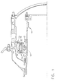
- Figure 1 depicts a portion of an enclosed chamber or "sump" of a gas turbine engine, which in this case is a turboshaft engine.
- a gas turbine engine which in this case is a turboshaft engine.
- turbomachinery such as turbojet, turboprop, and turbofan engines, as well as other types of machinery which use bearing dampers.
- a shaft 10 of the engine is supported for rotation in a rolling-element bearing 12, in this case a roller bearing.
- a static annular frame member 14 surrounds the bearing 12.
- the bearing 12 is carried by the frame member 14 through a squeeze film bearing damper 16, which is described in more detail below.
- the bearing 12 includes an annular inner race 18 mounted on the shaft 10, a plurality of rollers 20 restrained by a cage 22, and an annular outer race 24.
- the frame member 14 incorporates a radially-inwardly extending arm 26, the inboard end of which defines a housing 28.
- the housing 28 includes a recess 30 (see Figure 2 ) that receives the bearing damper 16.
- the housing forms the forward end and outer wall of the recess, and the aft end of the recess 30 is closed off by a separate annular retainer 32 which is secured to the housing 28, for example using threaded studs 34 and nuts 36, or other fasteners. This configuration facilitates removal and replacement of the damper 16 and/or bearing 12.
- FIG. 2 illustrates the damper 16 in more detail.
- the recess 30 of the housing 28 is annular with a generally rectangular cross-sectional shape having forward and aft ends 38 and 40, respectively.
- An annular sleeve 42 is received in the recess 30.
- the sleeve 42 is stationary in operation and is secured against rotation within the housing 28, for example through an interference fit. Any alloy which has a suitable life in the application may be used.
- the sleeve 42 may be made from a lightweight material such as aluminum or titanium alloy.
- a forward groove 44 having a square cross-section is formed in the inner surface 48 of the sleeve 42 adjacent the forward end 38 of the recess 30, and an aft groove 46 having a square cross-section is formed in the inner surface 48 of the sleeve 42 adjacent the aft end 40 of the recess 30.
- the outer race 24 of the bearing 12 is received in the recess 30 inboard of the sleeve 42.
- the outer race 24 (and consequently the remainder of the bearing 12) is restrained from moving in an axial direction but is free to move radially to some degree.
- a small annular gap 50 is provided between the inner surface 48 of the sleeve 42 and the outer surface of the outer race 24.
- Means are provided, in a known manner, for circulating pressurized oil through this annular gap 50.
- oil circulation may be implemented by providing supply and scavenge passages (not shown) in the housing 28 and/or sleeve 42 which are connected to an oil pump (not shown).
- any shaft rotor imbalance upon rotation of shaft 10, any shaft rotor imbalance will cause shaft 10 and bearing 12 to undergo radial motion and subject oil in the annular gap 50 to very high pressure to force viscous flow of the oil and cause a damping action on the outer race 24.
- An annular seal ring 54 is assembled into each of the forward and aft grooves 44 and 46.
- the seal ring 54 is a continuous "O"-ring element having a circular cross-section. Any material with appropriate stiffness and fatigue life may be used to construct the seal ring 54.
- the geometry of the seal ring cross section, such as the wall thickness, diameter, etc. may be selected to provide desired stiffness characteristics for the seal ring 54, for example the spring constant "K" in the radial direction.
- the functional characteristics of the seal ring 54 may be further tuned and optimized by combining a spring (not shown) in series with the seal ring 54.
- the seal rings 54 resiliently bear against the outer race 24 and seal off the forward and aft ends of the annular gap, and also provide a radial centering force on the bearing 12 that urges the outer race 24 into a position coaxial with the sleeve 42.
- Figure 3 illustrates an alternative damper configuration mounted in a recess 130 of a housing 128 which is identical to the housing 28 described above and which has forward and aft ends 138 and 140.
- a sleeve 142 having forward and aft grooves 144 and 146 is received in the recess 130.
- the outer race 124 of a bearing 112 is received in the recess 130 inboard of the sleeve 142.
- a small annular gap 150 is provided between an inner surface 148 of the sleeve 142 and the outer surface of the outer race 124.
- Identical annular seal rings 154 are assembled into each of the forward and aft grooves 144 and 146.
- the seal ring 154 has a cross-sectional shape which provides a resilient characteristic in the radial direction. Some examples include “Z”, “C”, “I”, or “T” shapes.
- the cross section is generally “Z” shaped including inner and outer flanges 56 and 58 interconnected by a web 60.
- the geometry of the seal ring cross section such as the material thickness, angle of the web 60, fillet radii, etc. may be selected to provide desired stiffness characteristics for the forward seal ring 154, for example the spring constant "K" in the radial direction.
- the seal rings 154 seal against the outer race 124 to close off the forward and aft ends of the annular gap 150, and also provide a radial centering force on the bearing 112 that urges the outer race 124 into a position coaxial with the sleeve 142.
- damper designs described above can be modified in various ways.
- the seal rings 54 or 154 and a portion of the sleeve 42 or 142 could be integrated as a single component to further reduce the assembly and part count.
- the functional characteristics of the seal ring 54 or 154 may be further tuned and optimized by combining a spring (not shown) in series with in the seal ring 54 or 154.
- the bearing damper configurations described herein provide multiple advantages over prior art film damper sealing technology. Combining the sealing function with the centering spring element eliminates the need for prior art piston rings that are used to seal the end leakage of the annular gap 50.
- the sleeve 42 which incorporates grooves for the seal rings 50 will be less expensive to manufacture, maintain, and repair compared to typical designs which require complex machining in a structural outer bearing race.
- the complete film damper system will be significantly less expensive as well. Sealing via 360° energized rings provides improved squeeze film damping action due to little or no side leakage. This completely eliminates any potential for high side leakage due to mis-assembly or misalignment of piston rings.
- the overall radial stiffness of the damper can be varied over a wide range. Outer race heat generation will be efficiently balanced by the sealed circumferential cavity that has a continuous circulating lubricant supply.
- the bearing damper will provide improved operating internal radial clearance (IRC) control for the bearing 12, and the overall reduced clearance range for the engine rotor-stator clearance provides net specific fuel consumption (SFC) improvements.
- IRC operating internal radial clearance
- SFC net specific fuel consumption
Landscapes
- Engineering & Computer Science (AREA)
- General Engineering & Computer Science (AREA)
- Mechanical Engineering (AREA)
- Support Of The Bearing (AREA)
- Rolling Contact Bearings (AREA)
Abstract
Description
- This invention relates generally to rotating bearings, and more particularly to squeeze film dampers for bearings associated with high speed turbomachinery.
- In a typical squeeze film shaft damper arrangement, a shaft with its associated rolling element bearing are permitted to have some limited radial motion in the supporting bearing housing. Ordinarily an annular outer race of a rolling element closely fits in an annular chamber in the support housing where two opposing closely adjacent circumferential surfaces of the housing and race define a thin annular squeeze film space into which an oil under pressure is introduced for damping action.
- The use of film dampers in gas turbine engines causes increased clearances for rotor blades and labyrinth seals leading to increased specific fuel consumption ("SFC") and reduced sealing margins. The effectiveness of the damper is generally improved if the clearance is increased and the damper is sealed. Prior art dampers for turbine engine applications are typically sealed with concentric piston ring type seals which circumferentially engage the bearing housing to seal off the squeeze film space between the rings.
- Some prior art dampers are mounted in a centralized spring structure, such as a squirrel cage. This is effective to limit clearances, but the spring structure increases the bearing cost and weight.
- These and other shortcomings of the prior art are addressed by various aspects and embodiments of the present invention, which provide a bearing damper with an integrated centering spring and sealing apparatus.
- According to one aspect of the invention, a bearing damper includes: (a) an annular sleeve having spaced-apart grooves formed in a radially-facing surface therein; (b) an annular bearing race received in the sleeve; and (c) a resilient seal ring disposed in each of the grooves, wherein the seal rings cooperate with the sleeve and a radially-facing surface of the bearing race to define a closed annular gap, and further wherein the seal rings are sized so as to urge the bearing race towards a coaxial position relative to the sleeve.
- According to another aspect of the invention a bearing support apparatus for a gas turbine engine includes: (a) a stationary housing which defines an annular recess; (b) an annular sleeve received in the recess, the sleeve having spaced-apart grooves formed therein; (c) a bearing having annular inner and outer races, the outer race received in the recess; (d) a shaft received in the inner race; and (e) a resilient seal ring disposed in each of the grooves, wherein the seal rings cooperate with the sleeve and the outer race to define a closed annular gap, and the seal rings are sized so as to urge the bearing towards a coaxial position relative to the sleeve.
- The invention may be best understood by reference to the following description taken in conjunction with the accompanying drawing figures in which:
-
Figure 1 is a cross-sectional view of a portion of a gas turbine engine showing a bearing sump thereof; -
Figure 2 is a perspective cross-sectional view of a portion of the bearing sump shown inFigure 1 , illustrating a spring damper seal constructed according to an aspect of the present invention; and -
Figure 3 is a perspective cross-sectional view of a portion of the bearing sump shown inFigure 1 , illustrating an alternative spring damper seal constructed according to an aspect of the present invention. - Referring to the drawings wherein identical reference numerals denote the same elements throughout the various views,
Figure 1 depicts a portion of an enclosed chamber or "sump" of a gas turbine engine, which in this case is a turboshaft engine. This is merely an example of a specific application, and the principles of the present invention are equally applicable to all kinds of turbomachinery such as turbojet, turboprop, and turbofan engines, as well as other types of machinery which use bearing dampers. - Within the sump, a
shaft 10 of the engine is supported for rotation in a rolling-element bearing 12, in this case a roller bearing. A staticannular frame member 14 surrounds thebearing 12. Thebearing 12 is carried by theframe member 14 through a squeezefilm bearing damper 16, which is described in more detail below. Thebearing 12 includes an annularinner race 18 mounted on theshaft 10, a plurality ofrollers 20 restrained by acage 22, and an annularouter race 24. - The
frame member 14 incorporates a radially-inwardly extendingarm 26, the inboard end of which defines ahousing 28. Thehousing 28 includes a recess 30 (seeFigure 2 ) that receives thebearing damper 16. In the illustrated example the housing forms the forward end and outer wall of the recess, and the aft end of therecess 30 is closed off by a separateannular retainer 32 which is secured to thehousing 28, for example using threadedstuds 34 andnuts 36, or other fasteners. This configuration facilitates removal and replacement of thedamper 16 and/or bearing 12. -
Figure 2 illustrates thedamper 16 in more detail. Therecess 30 of thehousing 28 is annular with a generally rectangular cross-sectional shape having forward andaft ends annular sleeve 42 is received in therecess 30. Thesleeve 42 is stationary in operation and is secured against rotation within thehousing 28, for example through an interference fit. Any alloy which has a suitable life in the application may be used. For weight savings, thesleeve 42 may be made from a lightweight material such as aluminum or titanium alloy. Aforward groove 44 having a square cross-section is formed in theinner surface 48 of thesleeve 42 adjacent theforward end 38 of therecess 30, and anaft groove 46 having a square cross-section is formed in theinner surface 48 of thesleeve 42 adjacent theaft end 40 of therecess 30. - The
outer race 24 of thebearing 12 is received in therecess 30 inboard of thesleeve 42. The outer race 24 (and consequently the remainder of the bearing 12) is restrained from moving in an axial direction but is free to move radially to some degree. A smallannular gap 50 is provided between theinner surface 48 of thesleeve 42 and the outer surface of theouter race 24. Means are provided, in a known manner, for circulating pressurized oil through thisannular gap 50. For example, oil circulation may be implemented by providing supply and scavenge passages (not shown) in thehousing 28 and/orsleeve 42 which are connected to an oil pump (not shown). In a known manner, upon rotation ofshaft 10, any shaft rotor imbalance will causeshaft 10 and bearing 12 to undergo radial motion and subject oil in theannular gap 50 to very high pressure to force viscous flow of the oil and cause a damping action on theouter race 24. - An
annular seal ring 54 is assembled into each of the forward andaft grooves seal ring 54 is a continuous "O"-ring element having a circular cross-section. Any material with appropriate stiffness and fatigue life may be used to construct theseal ring 54. The geometry of the seal ring cross section, such as the wall thickness, diameter, etc. may be selected to provide desired stiffness characteristics for theseal ring 54, for example the spring constant "K" in the radial direction. The functional characteristics of theseal ring 54 may be further tuned and optimized by combining a spring (not shown) in series with theseal ring 54. The seal rings 54 resiliently bear against theouter race 24 and seal off the forward and aft ends of the annular gap, and also provide a radial centering force on thebearing 12 that urges theouter race 24 into a position coaxial with thesleeve 42. -
Figure 3 illustrates an alternative damper configuration mounted in arecess 130 of ahousing 128 which is identical to thehousing 28 described above and which has forward andaft ends sleeve 142 having forward andaft grooves recess 130. Theouter race 124 of abearing 112 is received in therecess 130 inboard of thesleeve 142. A smallannular gap 150 is provided between aninner surface 148 of thesleeve 142 and the outer surface of theouter race 124. - Identical
annular seal rings 154 are assembled into each of the forward andaft grooves seal ring 154 has a cross-sectional shape which provides a resilient characteristic in the radial direction. Some examples include "Z", "C", "I", or "T" shapes. In this particular example, the cross section is generally "Z" shaped including inner andouter flanges 56 and 58 interconnected by aweb 60. The geometry of the seal ring cross section, such as the material thickness, angle of theweb 60, fillet radii, etc. may be selected to provide desired stiffness characteristics for theforward seal ring 154, for example the spring constant "K" in the radial direction. The seal rings 154 seal against theouter race 124 to close off the forward and aft ends of theannular gap 150, and also provide a radial centering force on thebearing 112 that urges theouter race 124 into a position coaxial with thesleeve 142. - The damper designs described above can be modified in various ways. For example, the
seal rings sleeve seal ring seal ring - The bearing damper configurations described herein provide multiple advantages over prior art film damper sealing technology. Combining the sealing function with the centering spring element eliminates the need for prior art piston rings that are used to seal the end leakage of the
annular gap 50. Thesleeve 42 which incorporates grooves for theseal rings 50 will be less expensive to manufacture, maintain, and repair compared to typical designs which require complex machining in a structural outer bearing race. The complete film damper system will be significantly less expensive as well. Sealing via 360° energized rings provides improved squeeze film damping action due to little or no side leakage. This completely eliminates any potential for high side leakage due to mis-assembly or misalignment of piston rings. The overall radial stiffness of the damper can be varied over a wide range. Outer race heat generation will be efficiently balanced by the sealed circumferential cavity that has a continuous circulating lubricant supply. - The bearing damper will provide improved operating internal radial clearance (IRC) control for the
bearing 12, and the overall reduced clearance range for the engine rotor-stator clearance provides net specific fuel consumption (SFC) improvements. - The foregoing has described a spring seal damper for a gas turbine engine. While specific embodiments of the present invention have been described, it will be apparent to those skilled in the art that various modifications thereto can be made without departing from the spirit and scope of the invention. Accordingly, the foregoing description of the preferred embodiment of the invention and the best mode for practicing the invention are provided for the purpose of illustration only and not for the purpose of limitation.
- Various aspects and embodiments of the present invention are defined by the following numbered clauses:
- 1. A bearing damper, comprising:
- (a) an annular sleeve having spaced-apart grooves formed in a radially-facing surface therein;
- (b) an annular bearing race received in the sleeve; and
- (c) a resilient seal ring disposed in each of the grooves, wherein the seal rings cooperate with the sleeve and a radially-facing surface of the bearing race to define a closed annular gap, and further wherein the seal rings are sized so as to urge the bearing race towards a coaxial position relative to the sleeve.
- 2. The bearing damper of clause 1 wherein each of the seal rings has a generally circular cross-sectional shape.
- 3. The bearing damper of any preceding clause wherein each of the seal rings has a Z-shaped cross-sectional shape comprising inner and outer flanges interconnected by a web.
- 4. The bearing damper of any preceding clause wherein the radially-facing surface of the sleeve faces radially inwards, and the radially-facing surface of the bearing race faces radially outwards.
- 5. The bearing damper of any preceding clause where the bearing race is an outer race of a bearing which includes a plurality of rolling elements disposed between the outer race and an inner race.
- 6. The bearing damper of any preceding clause where each of the seal rings is a continuous member.
- 7. A bearing support apparatus for a gas turbine engine, comprising:
- (a) a stationary housing which defines an annular recess;
- (b) an annular sleeve received in the recess, the sleeve having spaced-apart grooves formed therein;
- (c) a bearing having annular inner and outer races, the outer race received in the recess;
- (d) a shaft received in the inner race; and
- (e) a resilient seal ring disposed in each of the grooves, wherein the seal rings cooperate with the sleeve and the outer race to define a closed annular gap, and the seal rings are sized so as to urge the bearing towards a coaxial position relative to the sleeve.
- 8. The bearing support apparatus of any preceding clause wherein each of the seal rings has a generally circular cross-sectional shape.
- 9. The bearing support apparatus of any preceding clause wherein each of the seal rings has a Z-shaped cross-sectional shape comprising inner and outer flanges interconnected by a web.
- 10. The bearing support apparatus of any preceding clause wherein the bearing race is an outer race.
- 11. The bearing support apparatus of any preceding clause wherein the bearing race is an outer race of a bearing which includes a plurality of rolling elements disposed between the outer race and an inner race.
- 12. The bearing support apparatus of any preceding clause wherein each of the seal rings is a continuous member.
- 13. The bearing support apparatus of any preceding clause wherein the housing defines a first axial end and an outer wall of the recess, and an a second axial end of the recess is closed off by a separate annular retainer which is secured to the housing.
Claims (10)
- A bearing damper, comprising:(a) an annular sleeve (42) having spaced-apart grooves (44, 46) formed in a radially-facing surface therein;(b) an annular bearing race (24) received in the sleeve (42); and(c) a resilient seal ring (54, 154) disposed in each of the grooves (44, 46), wherein the seal rings (54, 154) cooperate with the sleeve (42) and a radially-facing surface of the bearing race (24) to define a closed annular gap, and further wherein the seal rings (54, 154) are sized so as to urge the bearing race (24) towards a coaxial position relative to the sleeve (42).
- The bearing damper of claim 1 wherein the radially-facing surface of the sleeve (42) faces radially inwards, and the radially-facing surface of the bearing race (24) faces radially outwards.
- The bearing dampler of any preceding claim wherein the bearing race (24) is an outer race.
- The bearing damper of any preceding claim where the bearing race (24) is an outer race of a bearing which includes a plurality of rolling elements (20) disposed between the outer race (24) and an inner race (18).
- A bearing support apparatus for a gas turbine engine, comprising:(a) a stationary housing (28) which defines an annular recess (30);(b) an annular sleeve (42) received in the recess (30), the sleeve (42) having spaced-apart grooves (44, 46) formed therein;(c) a bearing having annular inner and outer races, the outer race (24) received in the recess (30);(d) a shaft received in the inner race (18); and(e) a resilient seal ring (54, 154) disposed in each of the grooves (44, 46), wherein the seal rings (54, 154) cooperate with the sleeve (42) and the outer race (24) to define a closed annular gap, and the seal rings (54, 154) are sized so as to urge the bearing towards a coaxial position relative to the sleeve (42).
- The bearing support apparatus of claim 5 wherein the bearing includes a plurality of rolling elements (20) disposed between the outer race (24) and an inner race (18).
- The bearing support apparatus of claim 5 or claim 6 wherein the housing (28) defines a first axial end and an outer wall of the recess (30), and a second axial end of the recess (30) is closed off by a separate annular retainer (32) which is secured to the housing (28).
- The device of any preceding claim wherein each of the seal rings (54) has a generally circular cross-sectional shape.
- The device of any preceding claim wherein wherein each of the seal rings (154) has a Z-shaped cross-sectional shape comprising inner and outer flanges interconnected by a web.
- The device of any preceding claim wherein each of the seal rings (54, 154) is a continuous member.
Applications Claiming Priority (1)
| Application Number | Priority Date | Filing Date | Title |
|---|---|---|---|
| US12/395,074 US8182153B2 (en) | 2009-02-27 | 2009-02-27 | Bearing damper with spring seal |
Publications (3)
| Publication Number | Publication Date |
|---|---|
| EP2224103A2 true EP2224103A2 (en) | 2010-09-01 |
| EP2224103A3 EP2224103A3 (en) | 2013-01-23 |
| EP2224103B1 EP2224103B1 (en) | 2015-07-15 |
Family
ID=42142726
Family Applications (1)
| Application Number | Title | Priority Date | Filing Date |
|---|---|---|---|
| EP10153134.1A Active EP2224103B1 (en) | 2009-02-27 | 2010-02-10 | Bearing support apparatus with squeeze film damper |
Country Status (4)
| Country | Link |
|---|---|
| US (1) | US8182153B2 (en) |
| EP (1) | EP2224103B1 (en) |
| CA (1) | CA2693625A1 (en) |
| ES (1) | ES2550395T3 (en) |
Cited By (8)
| Publication number | Priority date | Publication date | Assignee | Title |
|---|---|---|---|---|
| WO2014000799A1 (en) * | 2012-06-28 | 2014-01-03 | Aktiebolaget Skf | Machine arrangement |
| CN104534018A (en) * | 2014-12-18 | 2015-04-22 | 东南大学 | Suspension type multilayer oil film damper with rolling spherical hinge connection |
| EP3159559A1 (en) * | 2015-09-01 | 2017-04-26 | Rolls-Royce North American Technologies, Inc. | Squeeze film damper system for a gas turbine engine with radial springs containing a magneto-rheological fluid |
| CN109723725A (en) * | 2019-01-18 | 2019-05-07 | 宁波市江北甬丰轴承有限公司 | A kind of bearing cap for bearing oil leakproof |
| EP3719266A1 (en) * | 2019-04-05 | 2020-10-07 | United Technologies Corporation | Assembly for a bearing compartment of a gas turbine engine |
| CN111902610A (en) * | 2018-03-23 | 2020-11-06 | 赛峰飞机发动机公司 | Bearing support for an aircraft engine made by additive manufacturing |
| EP4592545A1 (en) * | 2024-01-26 | 2025-07-30 | Pratt & Whitney Canada Corp. | Flexible support for aircraft motor bearing |
| EP4592544A1 (en) * | 2024-01-23 | 2025-07-30 | Pratt & Whitney Canada Corp. | Flexible support for aircraft motor bearing |
Families Citing this family (39)
| Publication number | Priority date | Publication date | Assignee | Title |
|---|---|---|---|---|
| US7625121B2 (en) * | 2005-09-28 | 2009-12-01 | Elliott Company | Bearing assembly and centering support structure therefor |
| US20070179688A1 (en) * | 2005-12-30 | 2007-08-02 | Canadian National Railway Company | System and method for computing rail car switching solutions in a switchyard |
| WO2010043248A1 (en) * | 2008-10-14 | 2010-04-22 | Aktiebolaget Skf | Seal for rolling bearing, in particular for rolling bearing used in a wind turbine |
| US8070435B1 (en) * | 2009-03-17 | 2011-12-06 | Florida Turbine Technologies, Inc. | Split ring wedge bearing damper |
| US8967301B2 (en) * | 2010-02-03 | 2015-03-03 | Baker Hughes Incorporated | Composite metallic elastomeric sealing components for roller cone drill bits |
| US8994237B2 (en) | 2010-12-30 | 2015-03-31 | Dresser-Rand Company | Method for on-line detection of liquid and potential for the occurrence of resistance to ground faults in active magnetic bearing systems |
| EP2659277B8 (en) | 2010-12-30 | 2018-05-23 | Dresser-Rand Company | Method for on-line detection of resistance-to-ground faults in active magnetic bearing systems |
| US9551349B2 (en) | 2011-04-08 | 2017-01-24 | Dresser-Rand Company | Circulating dielectric oil cooling system for canned bearings and canned electronics |
| US8876389B2 (en) | 2011-05-27 | 2014-11-04 | Dresser-Rand Company | Segmented coast-down bearing for magnetic bearing systems |
| US8851756B2 (en) * | 2011-06-29 | 2014-10-07 | Dresser-Rand Company | Whirl inhibiting coast-down bearing for magnetic bearing systems |
| CN104246145B (en) * | 2012-04-25 | 2016-08-17 | 通用电气公司 | For assembling the apparatus and method of damper shaft bearing assembly |
| CN104968896B (en) * | 2012-10-26 | 2016-12-14 | 博格华纳公司 | Fluid Film Hydrodynamic Flexure Pivot Tilting Pad Semi-floating Ring Journal Bearing with Compliant Damper |
| US10138757B2 (en) | 2013-08-20 | 2018-11-27 | United Technologies Corporation | Bearing system for gas turbine engine |
| US9599152B2 (en) | 2014-04-21 | 2017-03-21 | Solar Turbines Incorporated | Compact squeeze film damper bearing |
| US9933012B1 (en) | 2015-02-09 | 2018-04-03 | United Technologies Corporation | Bearing centering spring with integral outer rings |
| US9714584B2 (en) | 2015-06-18 | 2017-07-25 | United Technologies Corporation | Bearing support damping |
| US9726225B2 (en) * | 2015-10-28 | 2017-08-08 | Deere & Company | Distributed load bearing with an outer flex ring |
| US10274071B2 (en) | 2016-01-28 | 2019-04-30 | General Electric Company | Gearbox planet squeeze film damper |
| US9677659B1 (en) | 2016-01-28 | 2017-06-13 | General Electric Company | Gearbox planet attenuation spring damper |
| US10113633B2 (en) * | 2016-01-28 | 2018-10-30 | General Electric Company | Gearbox planet squeeze film damper |
| US10358942B2 (en) * | 2016-02-25 | 2019-07-23 | General Electric Company | Core differential bearing with centering spring and squeeze film damper |
| US9926975B2 (en) | 2016-03-22 | 2018-03-27 | United Technologies Corporation | Centering spring and damper assembly |
| US10161264B2 (en) | 2017-04-24 | 2018-12-25 | United Technologies Corporation | Helically actuated variable bearing damper |
| US10941849B2 (en) * | 2017-08-03 | 2021-03-09 | General Electric Company | Gear assembly damper arrangement |
| US10156159B1 (en) | 2017-08-22 | 2018-12-18 | General Electric Company | Squeeze film damper for a gas turbine engine |
| US10352194B2 (en) * | 2017-08-30 | 2019-07-16 | United Technologies Corporation | Damper with adjustable seal |
| US11041495B2 (en) * | 2017-12-19 | 2021-06-22 | Ingersoll-Rand Industrial U.S., Inc. | Positive displacement compressor and damper bearing system |
| US10480572B2 (en) | 2018-04-18 | 2019-11-19 | United Technologies Corporation | Bearing centering spring and damper |
| US10801366B2 (en) * | 2018-05-15 | 2020-10-13 | General Electric Company | Variable stiffness bearing housing |
| US10495144B1 (en) * | 2018-05-25 | 2019-12-03 | Borgwarner Inc. | Single-row ball bearing with integrated squeeze-film damper |
| US10767511B2 (en) * | 2019-01-21 | 2020-09-08 | Pratt & Whitney Canada Corp. | Anti-cavitation device for oil dampers |
| FR3091902B1 (en) * | 2019-01-23 | 2021-07-02 | Safran Aircraft Engines | Device for centering and guiding in rotation a turbomachine shaft comprising several optimized damping fluid films |
| US10844746B2 (en) | 2019-03-29 | 2020-11-24 | Pratt & Whitney Canada Corp. | Bearing housing |
| US11448081B2 (en) * | 2019-10-18 | 2022-09-20 | Raytheon Technologies Corporation | Balanced circumferential seal |
| US11795839B2 (en) * | 2020-08-25 | 2023-10-24 | Rolls-Royce Deutschland Ltd & Co Kg | Structural assembly for a gas turbine engine |
| US11674397B2 (en) | 2020-11-18 | 2023-06-13 | General Electric Company | Variable stiffness damper system |
| FR3120904B1 (en) * | 2021-03-18 | 2023-03-24 | Safran Aircraft Engines | CENTERING AND GUIDE DEVICE FOR AN AIRCRAFT TURBOMACHINE SHAFT |
| US12392372B2 (en) * | 2024-01-30 | 2025-08-19 | Miba Industrial Bearings U.S. LLC | Squeeze film damper and a rotating machinery |
| CN120007748B (en) * | 2025-04-03 | 2026-01-06 | 沈阳航空航天大学 | A multi-stage damping oil film damper for suppressing vapor cavitation |
Family Cites Families (41)
| Publication number | Priority date | Publication date | Assignee | Title |
|---|---|---|---|---|
| JPS6020603B2 (en) * | 1977-08-10 | 1985-05-23 | 日本精工株式会社 | Rolling bearing with cage |
| US4214796A (en) * | 1978-10-19 | 1980-07-29 | General Electric Company | Bearing assembly with multiple squeeze film damper apparatus |
| JPS55107114A (en) * | 1979-02-13 | 1980-08-16 | Hitachi Ltd | Vibration-damping bearing |
| US4457667A (en) * | 1980-12-11 | 1984-07-03 | United Technologies Corporation | Viscous damper with rotor centering means |
| US4669893A (en) * | 1986-02-18 | 1987-06-02 | United Technologies Corporation | Annular oil damper arrangement |
| DE3628687A1 (en) * | 1986-08-23 | 1988-02-25 | Daimler Benz Ag | STORAGE OF THE WHEELS OF THE COMPRESSOR AND TURBINE ON A SHAFT END OF A ROTOR SHAFT IN THE TURBINE HOUSING |
| US4775248A (en) * | 1987-12-16 | 1988-10-04 | United Technologies Corporation | Multiple feed oil supply system for fluid damper |
| US4981415A (en) * | 1989-08-16 | 1991-01-01 | United Technologies Corporation | Support for oil film dampers |
| US4971457A (en) * | 1989-10-04 | 1990-11-20 | United Technologies Corporation | Fluid damper |
| US4992024A (en) * | 1989-12-13 | 1991-02-12 | Allied-Signal Inc. | Multi-film fluid bearing damper |
| US5071262A (en) * | 1990-11-05 | 1991-12-10 | General Electric Company | Squeeze film damper fluid control |
| US5056935A (en) * | 1990-11-05 | 1991-10-15 | General Electric Company | Oil film damper seal ring |
| US5197807A (en) * | 1991-01-08 | 1993-03-30 | General Electric Company | Squeeze film damper seal ring |
| US5178400A (en) * | 1991-01-14 | 1993-01-12 | General Electric Company | Squeeze film damper seal |
| US5085521A (en) * | 1991-01-14 | 1992-02-04 | General Electric Company | Squeeze film damper seal |
| US5048978A (en) * | 1991-01-14 | 1991-09-17 | General Electric Company | Squeeze film damper seal |
| US5188375A (en) * | 1991-02-19 | 1993-02-23 | General Electric Company | Squeeze film damper piston ring seal |
| US5106208A (en) * | 1991-04-17 | 1992-04-21 | General Electric Company | Proportioned piston ring seals |
| US5169240A (en) * | 1991-04-17 | 1992-12-08 | General Electric Company | Proportioned piston ring seals |
| US5228784A (en) * | 1991-05-16 | 1993-07-20 | General Electric Company | Squeeze film damper composite ring seal |
| US5207511A (en) * | 1991-07-22 | 1993-05-04 | General Electric Company | Squeeze film damper oil control |
| US5251985A (en) * | 1991-09-26 | 1993-10-12 | General Electric Company | Squeeze film damper seal |
| US5169241A (en) * | 1991-10-04 | 1992-12-08 | General Electric Company | Squeeze film shaft damper oil system |
| US5201585A (en) * | 1991-12-31 | 1993-04-13 | General Electric Company | Fluid film journal bearing with squeeze film damper for turbomachinery |
| US5215384A (en) * | 1992-04-16 | 1993-06-01 | Dresser-Rand Company | Self-centering squeeze film damper bearing |
| US5344239A (en) * | 1992-11-25 | 1994-09-06 | General Electric Company | Squeeze film bearing damper with annular end plenums |
| US5374129A (en) * | 1994-03-15 | 1994-12-20 | General Electric Co. | Hydrostatic bearing support affording high static and low dynamic stiffness to a rotor in turbomachinery |
| JPH09112549A (en) * | 1995-10-17 | 1997-05-02 | Mitsubishi Heavy Ind Ltd | Squeeze film damper |
| US6071076A (en) * | 1997-12-16 | 2000-06-06 | General Electric Company | Actuation system for a gas turbine rotor blade |
| US6135639A (en) * | 1998-12-28 | 2000-10-24 | General Electric Company | Fixed arc squeeze film bearing damper |
| EP1174629A1 (en) * | 2000-06-30 | 2002-01-23 | Techspace Aero S.A. | Sealing device of a squeeze film damper incorporated in a rolling element bearing |
| EP1167788A1 (en) * | 2000-06-30 | 2002-01-02 | Techspace Aero S.A. | Sealing device of a squeeze film damper incorporated in a rolling element bearing |
| FR2845138B1 (en) * | 2002-10-01 | 2004-12-17 | Snecma Moteurs | BEARING BEARING AMORTIZED WITH OIL |
| US7182519B2 (en) * | 2004-06-24 | 2007-02-27 | General Electric Company | Methods and apparatus for assembling a bearing assembly |
| US7296398B2 (en) * | 2004-10-29 | 2007-11-20 | General Electric Company | Counter-rotating turbine engine and method of assembling same |
| US7334982B2 (en) * | 2005-05-06 | 2008-02-26 | General Electric Company | Apparatus for scavenging lubricating oil |
| US7329048B2 (en) * | 2005-07-19 | 2008-02-12 | Rolls-Royce Corporation | Self contained squeeze film damping system |
| US7625121B2 (en) * | 2005-09-28 | 2009-12-01 | Elliott Company | Bearing assembly and centering support structure therefor |
| US7665897B2 (en) * | 2006-01-17 | 2010-02-23 | Honeywell International Inc. | Squeeze film damper using low pressure oil |
| US7517152B1 (en) * | 2006-09-20 | 2009-04-14 | Florida Turbine Technologies, Inc. | Squeeze film damper with variable support stiffness |
| FR2934339B1 (en) * | 2008-07-25 | 2010-09-03 | Mecanique Magnetique Sa | INSENSITIVE EMERGENCY BEARING WITH AXIAL LOAD |
-
2009
- 2009-02-27 US US12/395,074 patent/US8182153B2/en active Active
-
2010
- 2010-02-10 ES ES10153134.1T patent/ES2550395T3/en active Active
- 2010-02-10 EP EP10153134.1A patent/EP2224103B1/en active Active
- 2010-02-18 CA CA2693625A patent/CA2693625A1/en not_active Abandoned
Non-Patent Citations (1)
| Title |
|---|
| None |
Cited By (10)
| Publication number | Priority date | Publication date | Assignee | Title |
|---|---|---|---|---|
| WO2014000799A1 (en) * | 2012-06-28 | 2014-01-03 | Aktiebolaget Skf | Machine arrangement |
| CN104534018A (en) * | 2014-12-18 | 2015-04-22 | 东南大学 | Suspension type multilayer oil film damper with rolling spherical hinge connection |
| EP3159559A1 (en) * | 2015-09-01 | 2017-04-26 | Rolls-Royce North American Technologies, Inc. | Squeeze film damper system for a gas turbine engine with radial springs containing a magneto-rheological fluid |
| US10465557B2 (en) | 2015-09-01 | 2019-11-05 | Rolls-Royce North American Technologies, Inc. | Magnetic squeeze film damper system for a gas turbine engine |
| CN111902610A (en) * | 2018-03-23 | 2020-11-06 | 赛峰飞机发动机公司 | Bearing support for an aircraft engine made by additive manufacturing |
| CN109723725A (en) * | 2019-01-18 | 2019-05-07 | 宁波市江北甬丰轴承有限公司 | A kind of bearing cap for bearing oil leakproof |
| CN109723725B (en) * | 2019-01-18 | 2020-12-15 | 新昌县恒利轴承有限公司 | A bearing cap for preventing leakage of bearing lubricating oil |
| EP3719266A1 (en) * | 2019-04-05 | 2020-10-07 | United Technologies Corporation | Assembly for a bearing compartment of a gas turbine engine |
| EP4592544A1 (en) * | 2024-01-23 | 2025-07-30 | Pratt & Whitney Canada Corp. | Flexible support for aircraft motor bearing |
| EP4592545A1 (en) * | 2024-01-26 | 2025-07-30 | Pratt & Whitney Canada Corp. | Flexible support for aircraft motor bearing |
Also Published As
| Publication number | Publication date |
|---|---|
| US20100220948A1 (en) | 2010-09-02 |
| US8182153B2 (en) | 2012-05-22 |
| CA2693625A1 (en) | 2010-08-27 |
| EP2224103A3 (en) | 2013-01-23 |
| ES2550395T3 (en) | 2015-11-06 |
| EP2224103B1 (en) | 2015-07-15 |
Similar Documents
| Publication | Publication Date | Title |
|---|---|---|
| EP2224103B1 (en) | Bearing support apparatus with squeeze film damper | |
| US9841056B2 (en) | Bearing with drained race and squeeze film damper | |
| US8727632B2 (en) | Bearing support apparatus for a gas turbine engine | |
| US8337090B2 (en) | Bearing support flexible ring | |
| US9879607B2 (en) | Sealing of turbine engine enclosures produced by brush seal and labyrinth | |
| US20130108440A1 (en) | Series bearing support apparatus for a gas turbine engine | |
| US11199103B2 (en) | Seal assembly for a turbomachine | |
| JP2017150484A (en) | Core differential bearing with centering spring and squeeze film damper | |
| US10352193B2 (en) | Bearing centering spring and damper | |
| EP3252280B1 (en) | Circumferential plenum for oil damper | |
| EP3287674A1 (en) | Floating, non-contact seal with offset building clearance for load imbalance | |
| US9933012B1 (en) | Bearing centering spring with integral outer rings | |
| US20190226585A1 (en) | Hydrodynamic Intershaft Piston Ring Seal | |
| US8070435B1 (en) | Split ring wedge bearing damper | |
| US20170030221A1 (en) | Bearing support housing for a gas turbine engine | |
| US10260563B2 (en) | Bearing cages for roller bearing assemblies | |
| US20240426222A1 (en) | Face seal robust to casing vibration | |
| EP4299933B1 (en) | Bearing-supported shaft assembly | |
| US20180335086A1 (en) | Bearing cages for roller bearing assemblies | |
| US10054163B2 (en) | Bearing cages for roller bearing assemblies |
Legal Events
| Date | Code | Title | Description |
|---|---|---|---|
| PUAI | Public reference made under article 153(3) epc to a published international application that has entered the european phase |
Free format text: ORIGINAL CODE: 0009012 |
|
| AK | Designated contracting states |
Kind code of ref document: A2 Designated state(s): AT BE BG CH CY CZ DE DK EE ES FI FR GB GR HR HU IE IS IT LI LT LU LV MC MK MT NL NO PL PT RO SE SI SK SM TR |
|
| AX | Request for extension of the european patent |
Extension state: AL BA RS |
|
| PUAL | Search report despatched |
Free format text: ORIGINAL CODE: 0009013 |
|
| AK | Designated contracting states |
Kind code of ref document: A3 Designated state(s): AT BE BG CH CY CZ DE DK EE ES FI FR GB GR HR HU IE IS IT LI LT LU LV MC MK MT NL NO PL PT RO SE SI SK SM TR |
|
| AX | Request for extension of the european patent |
Extension state: AL BA RS |
|
| RIC1 | Information provided on ipc code assigned before grant |
Ipc: F01D 25/16 20060101AFI20121220BHEP Ipc: F16C 27/04 20060101ALI20121220BHEP Ipc: F16F 15/023 20060101ALI20121220BHEP |
|
| 17P | Request for examination filed |
Effective date: 20130723 |
|
| RBV | Designated contracting states (corrected) |
Designated state(s): AT BE BG CH CY CZ DE DK EE ES FI FR GB GR HR HU IE IS IT LI LT LU LV MC MK MT NL NO PL PT RO SE SI SK SM TR |
|
| 17Q | First examination report despatched |
Effective date: 20140414 |
|
| GRAP | Despatch of communication of intention to grant a patent |
Free format text: ORIGINAL CODE: EPIDOSNIGR1 |
|
| INTG | Intention to grant announced |
Effective date: 20150216 |
|
| GRAS | Grant fee paid |
Free format text: ORIGINAL CODE: EPIDOSNIGR3 |
|
| GRAA | (expected) grant |
Free format text: ORIGINAL CODE: 0009210 |
|
| AK | Designated contracting states |
Kind code of ref document: B1 Designated state(s): AT BE BG CH CY CZ DE DK EE ES FI FR GB GR HR HU IE IS IT LI LT LU LV MC MK MT NL NO PL PT RO SE SI SK SM TR |
|
| REG | Reference to a national code |
Ref country code: CH Ref legal event code: EP Ref country code: GB Ref legal event code: FG4D |
|
| REG | Reference to a national code |
Ref country code: IE Ref legal event code: FG4D |
|
| REG | Reference to a national code |
Ref country code: AT Ref legal event code: REF Ref document number: 736919 Country of ref document: AT Kind code of ref document: T Effective date: 20150815 |
|
| REG | Reference to a national code |
Ref country code: DE Ref legal event code: R096 Ref document number: 602010025857 Country of ref document: DE |
|
| REG | Reference to a national code |
Ref country code: ES Ref legal event code: FG2A Ref document number: 2550395 Country of ref document: ES Kind code of ref document: T3 Effective date: 20151106 |
|
| REG | Reference to a national code |
Ref country code: AT Ref legal event code: MK05 Ref document number: 736919 Country of ref document: AT Kind code of ref document: T Effective date: 20150715 |
|
| REG | Reference to a national code |
Ref country code: NL Ref legal event code: MP Effective date: 20150715 |
|
| REG | Reference to a national code |
Ref country code: LT Ref legal event code: MG4D |
|
| PG25 | Lapsed in a contracting state [announced via postgrant information from national office to epo] |
Ref country code: GR Free format text: LAPSE BECAUSE OF FAILURE TO SUBMIT A TRANSLATION OF THE DESCRIPTION OR TO PAY THE FEE WITHIN THE PRESCRIBED TIME-LIMIT Effective date: 20151016 Ref country code: LT Free format text: LAPSE BECAUSE OF FAILURE TO SUBMIT A TRANSLATION OF THE DESCRIPTION OR TO PAY THE FEE WITHIN THE PRESCRIBED TIME-LIMIT Effective date: 20150715 Ref country code: LV Free format text: LAPSE BECAUSE OF FAILURE TO SUBMIT A TRANSLATION OF THE DESCRIPTION OR TO PAY THE FEE WITHIN THE PRESCRIBED TIME-LIMIT Effective date: 20150715 Ref country code: FI Free format text: LAPSE BECAUSE OF FAILURE TO SUBMIT A TRANSLATION OF THE DESCRIPTION OR TO PAY THE FEE WITHIN THE PRESCRIBED TIME-LIMIT Effective date: 20150715 Ref country code: NO Free format text: LAPSE BECAUSE OF FAILURE TO SUBMIT A TRANSLATION OF THE DESCRIPTION OR TO PAY THE FEE WITHIN THE PRESCRIBED TIME-LIMIT Effective date: 20151015 |
|
| REG | Reference to a national code |
Ref country code: FR Ref legal event code: PLFP Year of fee payment: 7 |
|
| PG25 | Lapsed in a contracting state [announced via postgrant information from national office to epo] |
Ref country code: PL Free format text: LAPSE BECAUSE OF FAILURE TO SUBMIT A TRANSLATION OF THE DESCRIPTION OR TO PAY THE FEE WITHIN THE PRESCRIBED TIME-LIMIT Effective date: 20150715 Ref country code: PT Free format text: LAPSE BECAUSE OF FAILURE TO SUBMIT A TRANSLATION OF THE DESCRIPTION OR TO PAY THE FEE WITHIN THE PRESCRIBED TIME-LIMIT Effective date: 20151116 Ref country code: SE Free format text: LAPSE BECAUSE OF FAILURE TO SUBMIT A TRANSLATION OF THE DESCRIPTION OR TO PAY THE FEE WITHIN THE PRESCRIBED TIME-LIMIT Effective date: 20150715 Ref country code: HR Free format text: LAPSE BECAUSE OF FAILURE TO SUBMIT A TRANSLATION OF THE DESCRIPTION OR TO PAY THE FEE WITHIN THE PRESCRIBED TIME-LIMIT Effective date: 20150715 Ref country code: AT Free format text: LAPSE BECAUSE OF FAILURE TO SUBMIT A TRANSLATION OF THE DESCRIPTION OR TO PAY THE FEE WITHIN THE PRESCRIBED TIME-LIMIT Effective date: 20150715 |
|
| REG | Reference to a national code |
Ref country code: DE Ref legal event code: R097 Ref document number: 602010025857 Country of ref document: DE |
|
| PG25 | Lapsed in a contracting state [announced via postgrant information from national office to epo] |
Ref country code: CZ Free format text: LAPSE BECAUSE OF FAILURE TO SUBMIT A TRANSLATION OF THE DESCRIPTION OR TO PAY THE FEE WITHIN THE PRESCRIBED TIME-LIMIT Effective date: 20150715 Ref country code: EE Free format text: LAPSE BECAUSE OF FAILURE TO SUBMIT A TRANSLATION OF THE DESCRIPTION OR TO PAY THE FEE WITHIN THE PRESCRIBED TIME-LIMIT Effective date: 20150715 Ref country code: DK Free format text: LAPSE BECAUSE OF FAILURE TO SUBMIT A TRANSLATION OF THE DESCRIPTION OR TO PAY THE FEE WITHIN THE PRESCRIBED TIME-LIMIT Effective date: 20150715 Ref country code: SK Free format text: LAPSE BECAUSE OF FAILURE TO SUBMIT A TRANSLATION OF THE DESCRIPTION OR TO PAY THE FEE WITHIN THE PRESCRIBED TIME-LIMIT Effective date: 20150715 Ref country code: IT Free format text: LAPSE BECAUSE OF FAILURE TO SUBMIT A TRANSLATION OF THE DESCRIPTION OR TO PAY THE FEE WITHIN THE PRESCRIBED TIME-LIMIT Effective date: 20150715 |
|
| PLBE | No opposition filed within time limit |
Free format text: ORIGINAL CODE: 0009261 |
|
| STAA | Information on the status of an ep patent application or granted ep patent |
Free format text: STATUS: NO OPPOSITION FILED WITHIN TIME LIMIT |
|
| PG25 | Lapsed in a contracting state [announced via postgrant information from national office to epo] |
Ref country code: RO Free format text: LAPSE BECAUSE OF FAILURE TO SUBMIT A TRANSLATION OF THE DESCRIPTION OR TO PAY THE FEE WITHIN THE PRESCRIBED TIME-LIMIT Effective date: 20150715 Ref country code: BE Free format text: LAPSE BECAUSE OF NON-PAYMENT OF DUE FEES Effective date: 20160229 |
|
| 26N | No opposition filed |
Effective date: 20160418 |
|
| PG25 | Lapsed in a contracting state [announced via postgrant information from national office to epo] |
Ref country code: IS Free format text: LAPSE BECAUSE OF FAILURE TO SUBMIT A TRANSLATION OF THE DESCRIPTION OR TO PAY THE FEE WITHIN THE PRESCRIBED TIME-LIMIT Effective date: 20150715 |
|
| PG25 | Lapsed in a contracting state [announced via postgrant information from national office to epo] |
Ref country code: SI Free format text: LAPSE BECAUSE OF FAILURE TO SUBMIT A TRANSLATION OF THE DESCRIPTION OR TO PAY THE FEE WITHIN THE PRESCRIBED TIME-LIMIT Effective date: 20150715 |
|
| PG25 | Lapsed in a contracting state [announced via postgrant information from national office to epo] |
Ref country code: LU Free format text: LAPSE BECAUSE OF FAILURE TO SUBMIT A TRANSLATION OF THE DESCRIPTION OR TO PAY THE FEE WITHIN THE PRESCRIBED TIME-LIMIT Effective date: 20160210 Ref country code: MC Free format text: LAPSE BECAUSE OF FAILURE TO SUBMIT A TRANSLATION OF THE DESCRIPTION OR TO PAY THE FEE WITHIN THE PRESCRIBED TIME-LIMIT Effective date: 20150715 |
|
| REG | Reference to a national code |
Ref country code: CH Ref legal event code: PL |
|
| PG25 | Lapsed in a contracting state [announced via postgrant information from national office to epo] |
Ref country code: CH Free format text: LAPSE BECAUSE OF NON-PAYMENT OF DUE FEES Effective date: 20160229 Ref country code: LI Free format text: LAPSE BECAUSE OF NON-PAYMENT OF DUE FEES Effective date: 20160229 |
|
| REG | Reference to a national code |
Ref country code: IE Ref legal event code: MM4A |
|
| PG25 | Lapsed in a contracting state [announced via postgrant information from national office to epo] |
Ref country code: BE Free format text: LAPSE BECAUSE OF FAILURE TO SUBMIT A TRANSLATION OF THE DESCRIPTION OR TO PAY THE FEE WITHIN THE PRESCRIBED TIME-LIMIT Effective date: 20150715 |
|
| PG25 | Lapsed in a contracting state [announced via postgrant information from national office to epo] |
Ref country code: IE Free format text: LAPSE BECAUSE OF NON-PAYMENT OF DUE FEES Effective date: 20160210 |
|
| REG | Reference to a national code |
Ref country code: FR Ref legal event code: PLFP Year of fee payment: 8 |
|
| PG25 | Lapsed in a contracting state [announced via postgrant information from national office to epo] |
Ref country code: NL Free format text: LAPSE BECAUSE OF FAILURE TO SUBMIT A TRANSLATION OF THE DESCRIPTION OR TO PAY THE FEE WITHIN THE PRESCRIBED TIME-LIMIT Effective date: 20150715 |
|
| PG25 | Lapsed in a contracting state [announced via postgrant information from national office to epo] |
Ref country code: MT Free format text: LAPSE BECAUSE OF FAILURE TO SUBMIT A TRANSLATION OF THE DESCRIPTION OR TO PAY THE FEE WITHIN THE PRESCRIBED TIME-LIMIT Effective date: 20150715 |
|
| REG | Reference to a national code |
Ref country code: FR Ref legal event code: PLFP Year of fee payment: 9 |
|
| PG25 | Lapsed in a contracting state [announced via postgrant information from national office to epo] |
Ref country code: CY Free format text: LAPSE BECAUSE OF FAILURE TO SUBMIT A TRANSLATION OF THE DESCRIPTION OR TO PAY THE FEE WITHIN THE PRESCRIBED TIME-LIMIT Effective date: 20150715 Ref country code: HU Free format text: LAPSE BECAUSE OF FAILURE TO SUBMIT A TRANSLATION OF THE DESCRIPTION OR TO PAY THE FEE WITHIN THE PRESCRIBED TIME-LIMIT; INVALID AB INITIO Effective date: 20100210 Ref country code: SM Free format text: LAPSE BECAUSE OF FAILURE TO SUBMIT A TRANSLATION OF THE DESCRIPTION OR TO PAY THE FEE WITHIN THE PRESCRIBED TIME-LIMIT Effective date: 20150715 |
|
| PG25 | Lapsed in a contracting state [announced via postgrant information from national office to epo] |
Ref country code: MT Free format text: LAPSE BECAUSE OF FAILURE TO SUBMIT A TRANSLATION OF THE DESCRIPTION OR TO PAY THE FEE WITHIN THE PRESCRIBED TIME-LIMIT Effective date: 20160229 Ref country code: TR Free format text: LAPSE BECAUSE OF FAILURE TO SUBMIT A TRANSLATION OF THE DESCRIPTION OR TO PAY THE FEE WITHIN THE PRESCRIBED TIME-LIMIT Effective date: 20150715 Ref country code: MK Free format text: LAPSE BECAUSE OF FAILURE TO SUBMIT A TRANSLATION OF THE DESCRIPTION OR TO PAY THE FEE WITHIN THE PRESCRIBED TIME-LIMIT Effective date: 20150715 |
|
| PG25 | Lapsed in a contracting state [announced via postgrant information from national office to epo] |
Ref country code: BG Free format text: LAPSE BECAUSE OF FAILURE TO SUBMIT A TRANSLATION OF THE DESCRIPTION OR TO PAY THE FEE WITHIN THE PRESCRIBED TIME-LIMIT Effective date: 20150715 |
|
| P01 | Opt-out of the competence of the unified patent court (upc) registered |
Effective date: 20230414 |
|
| PGFP | Annual fee paid to national office [announced via postgrant information from national office to epo] |
Ref country code: GB Payment date: 20260121 Year of fee payment: 17 |
|
| PGFP | Annual fee paid to national office [announced via postgrant information from national office to epo] |
Ref country code: ES Payment date: 20260302 Year of fee payment: 17 |
|
| PGFP | Annual fee paid to national office [announced via postgrant information from national office to epo] |
Ref country code: DE Payment date: 20260121 Year of fee payment: 17 |
|
| PGFP | Annual fee paid to national office [announced via postgrant information from national office to epo] |
Ref country code: FR Payment date: 20260121 Year of fee payment: 17 |