EP2222936B1 - Multi-position valves for fracturing and sand control associated completion methods - Google Patents
Multi-position valves for fracturing and sand control associated completion methods Download PDFInfo
- Publication number
- EP2222936B1 EP2222936B1 EP08857887.7A EP08857887A EP2222936B1 EP 2222936 B1 EP2222936 B1 EP 2222936B1 EP 08857887 A EP08857887 A EP 08857887A EP 2222936 B1 EP2222936 B1 EP 2222936B1
- Authority
- EP
- European Patent Office
- Prior art keywords
- sliding sleeve
- valved port
- shroud
- valved
- screen
- Prior art date
- Legal status (The legal status is an assumption and is not a legal conclusion. Google has not performed a legal analysis and makes no representation as to the accuracy of the status listed.)
- Active
Links
- 238000000034 method Methods 0.000 title claims description 18
- 239000004576 sand Substances 0.000 title description 4
- 238000004519 manufacturing process Methods 0.000 claims description 33
- 230000015572 biosynthetic process Effects 0.000 claims description 14
- 238000000151 deposition Methods 0.000 claims description 6
- 238000007789 sealing Methods 0.000 claims 3
- 238000013461 design Methods 0.000 description 11
- 239000000463 material Substances 0.000 description 7
- 239000002002 slurry Substances 0.000 description 7
- 239000012530 fluid Substances 0.000 description 6
- 238000012856 packing Methods 0.000 description 6
- 230000004888 barrier function Effects 0.000 description 5
- 230000008021 deposition Effects 0.000 description 5
- 238000002955 isolation Methods 0.000 description 5
- 230000000712 assembly Effects 0.000 description 4
- 238000000429 assembly Methods 0.000 description 4
- 230000008901 benefit Effects 0.000 description 3
- 238000003491 array Methods 0.000 description 2
- 238000004891 communication Methods 0.000 description 2
- 230000003628 erosive effect Effects 0.000 description 2
- 239000004215 Carbon black (E152) Substances 0.000 description 1
- 229930195733 hydrocarbon Natural products 0.000 description 1
- 125000001183 hydrocarbyl group Chemical group 0.000 description 1
- 230000013011 mating Effects 0.000 description 1
- 239000002184 metal Substances 0.000 description 1
- 238000012986 modification Methods 0.000 description 1
- 230000004048 modification Effects 0.000 description 1
- 230000008569 process Effects 0.000 description 1
- 238000012216 screening Methods 0.000 description 1
- 239000007787 solid Substances 0.000 description 1
Images


Classifications
-
- E—FIXED CONSTRUCTIONS
- E21—EARTH DRILLING; MINING
- E21B—EARTH DRILLING, e.g. DEEP DRILLING; OBTAINING OIL, GAS, WATER, SOLUBLE OR MELTABLE MATERIALS OR A SLURRY OF MINERALS FROM WELLS
- E21B43/00—Methods or apparatus for obtaining oil, gas, water, soluble or meltable materials or a slurry of minerals from wells
- E21B43/02—Subsoil filtering
- E21B43/04—Gravelling of wells
-
- E—FIXED CONSTRUCTIONS
- E21—EARTH DRILLING; MINING
- E21B—EARTH DRILLING, e.g. DEEP DRILLING; OBTAINING OIL, GAS, WATER, SOLUBLE OR MELTABLE MATERIALS OR A SLURRY OF MINERALS FROM WELLS
- E21B34/00—Valve arrangements for boreholes or wells
- E21B34/06—Valve arrangements for boreholes or wells in wells
-
- E—FIXED CONSTRUCTIONS
- E21—EARTH DRILLING; MINING
- E21B—EARTH DRILLING, e.g. DEEP DRILLING; OBTAINING OIL, GAS, WATER, SOLUBLE OR MELTABLE MATERIALS OR A SLURRY OF MINERALS FROM WELLS
- E21B43/00—Methods or apparatus for obtaining oil, gas, water, soluble or meltable materials or a slurry of minerals from wells
- E21B43/02—Subsoil filtering
- E21B43/08—Screens or liners
-
- E—FIXED CONSTRUCTIONS
- E21—EARTH DRILLING; MINING
- E21B—EARTH DRILLING, e.g. DEEP DRILLING; OBTAINING OIL, GAS, WATER, SOLUBLE OR MELTABLE MATERIALS OR A SLURRY OF MINERALS FROM WELLS
- E21B43/00—Methods or apparatus for obtaining oil, gas, water, soluble or meltable materials or a slurry of minerals from wells
- E21B43/14—Obtaining from a multiple-zone well
-
- E—FIXED CONSTRUCTIONS
- E21—EARTH DRILLING; MINING
- E21B—EARTH DRILLING, e.g. DEEP DRILLING; OBTAINING OIL, GAS, WATER, SOLUBLE OR MELTABLE MATERIALS OR A SLURRY OF MINERALS FROM WELLS
- E21B43/00—Methods or apparatus for obtaining oil, gas, water, soluble or meltable materials or a slurry of minerals from wells
- E21B43/25—Methods for stimulating production
- E21B43/26—Methods for stimulating production by forming crevices or fractures
- E21B43/261—Separate steps of (1) cementing, plugging or consolidating and (2) fracturing or attacking the formation
-
- E—FIXED CONSTRUCTIONS
- E21—EARTH DRILLING; MINING
- E21B—EARTH DRILLING, e.g. DEEP DRILLING; OBTAINING OIL, GAS, WATER, SOLUBLE OR MELTABLE MATERIALS OR A SLURRY OF MINERALS FROM WELLS
- E21B2200/00—Special features related to earth drilling for obtaining oil, gas or water
- E21B2200/06—Sleeve valves
Definitions
- the field of the invention relates to completion techniques involving fracturing and more particularly the ability to gravel pack and fracture discrete segments of a formation in a desired order through dedicated valved ports followed by configuring another valve for screened sand control duty to let production begin.
- a crossover tool and a separate run for sand control screens after the fracturing operation is not required.
- Typical completion sequences in the past involve running in an assembly of screens with a crossover tool and an isolation packer above the crossover tool.
- the crossover tool has a squeeze position where it eliminates a return path to allow fluid pumped down a work string and through the packer to cross over to the annulus outside the screen sections and into the formation through, for example, a cemented and perforated casing or in open hole.
- the casing could have telescoping members that are extendable into the formation and the tubular from which they extend could be cemented or not cemented.
- the fracture fluid in any event, would go into the annular space outside the screens and get squeezed into the formation that is isolated by the packer above the crossover tool and another downhole packer or the bottom of the hole.
- the crossover tool When a particular portion of a zone was fractured in this manner the crossover tool would be repositioned to allow a return path, usually through the annular space above the isolation packer and outside the work string so that a gravel packing operation could then begin. In the gravel packing operation, the gravel exits the crossover tool to the annular space outside the screens. Carrier fluid goes through the screens and back into the crossover tool to get through the packer above and into the annular space outside the work string and back to the surface.
- the system comprises a casing deployed in a well bore and a plurality of valves connected to the casing. Each valve is provided for establishing communication between the casing and a well zone.
- a zonal communication valve is provided, which is operable in three different positions, i.e., in a closed position, fully open position and in an open through a filter position.
- the valve is designed to have three layers, that is, a wall with a port, a sliding sleeve and the screening layer.
- the technique comprises introducing an isolation assembly to a well bore, wherein the isolation assembly comprises a liner, one or more sleeves and a plurality of swellable packers. Sleeves and swellable packers are disposed about the liner. A shifting tool inside the liner is deployed in order to actuate the sleeves so that an open position, a fully closed position and an open to screen position can be achieved. That is, a three-layer valve assembly is taught which is realized by the liner wall, the sleeve and the screen layer.
- a sand control screen assembly is known that is positionable within a production interval for a wellbore that traverses a subterranean hydrocarbon bearing formation.
- the screen assembly comprises a base pipe having openings in a sidewall section thereof that allow fluid flow therethrough, a filter medium fixedly positioned about the exterior of at least a portion of the base pipe, and one-way valves that allow a fluid flow through the openings of the base pipe in one direction.
- a completion tubular is placed in position adjacent the zone or zones to be fractured and produced. It features preferably sliding sleeve valves one series of which can be put in the wide open position after run in for gravel packing and fracturing zones one at a time or in any desired order. These valves are then closed and another series of valves can be opened wide but with a screen material juxtaposed in the flow passage to selectively produce from one or more fractured zones.
- An annular path behind the gravel can be provided by an offset screen to promote flow to the screened production port. The path can be a closed annulus that comes short of the production port or goes over it. For short runs an exterior screen or shroud can be eliminated for a sliding sleeve with multiple screened ports that can be opened in tandem.
- FIG. 1 is a schematic illustration of a wellbore 10 that can be cased or in open hole. There are perforations 12 into a formation 14.
- a string 16 is shown in part if FIG. 1 to the extent it spans a production interval defined between seals or packers 18 and 20. These seal locations can be polished bores in a cased hole or any type of packer.
- the two barriers 18 and 20 define a production interval 22. While only one interval is shown the string 16 can pass through multiple intervals that preferably have similar equipment so that access to them can occur in any desired order and access can be to one interval at a time or multiple intervals together.
- the string 16 for the interval 22 that is illustrated has a frac valve 24 that is preferably a sliding sleeve shown in the closed position in FIG. 1 for run in.
- Valve 24 regulates opening or openings 25 and is used in two positions. The closed position is shown in FIG. 1 and the wide open position is shown in FIG. 2 .
- gravel slurry can be squeezed into the formation 14 leaving the gravel 28 in the annular interval 22 just outside the proppant screen or shroud 29.
- Shroud 29 is sealed on opposite ends 30 and 32 and in between defines an annular flow area 34. While the shroud 29 is shown as one continuous unit, it can also be segmented with discrete or interconnected segments.
- the proppant 28 stays in the interval 22 and the carrier fluid is pumped into the formation 14 to complete the fracturing operation. At that point the valve 24 is closed and excess proppant 28 that is still in the string 16 can be circulated out to the surface using, for example, coiled tubing 36.
- the production valve 26 which is preferably a sliding sleeve with a screen material 38 in or over its ports is brought into alignment with ports 40 and production from the formation 14 begins.
- the screen material 38 can be fixed to either side of the string 16.
- the open position of production valve 26 results in the production flow being screened regardless of screen position and screen type. Flow can take a path of less resistance through the flow area 34 to reach the port 40. While such flow avoids most of the gravel pack 28 by design, the presence of passage 34 allows a greater flow to reach the ports 40 so as not to impede production.
- the presence of a screen material 38 at ports 40 serves to exclude solids that may have gotten into passage 34 through the coarse openings in shroud 29.
- the screen material 38 can be of a variety of designs such as a weave, conjoined spheres, porous sintered metal or equivalent designs that perform the function of a screen to keep gravel 28 out of the flow passage through string 16.
- valves 24 and 26 are preferably longitudinally shiftable sliding sleeves that can be operated with a shifting tool, hydraulic or pneumatic pressure or a variety of motor drivers, other styles of valves can be used.
- the valves can be a sleeve that rotates rather than shifts axially.
- a single valve assembly in an interval between barriers 18 and 20 is illustrated for valves 24 and 26 and their associated ports, multiple assemblies can be used with either discrete sleeves for a given row of associated openings or longer sleeves that can service multiple rows of associated openings that are axially displaced.
- FIGS. 4-6 correspond to FIGS. 1-3 with the only difference being the shroud 29 having an end 32 that is past the openings 40 so that the passage 34 goes directly to the ports 40.
- the valves 24 and 26 are closed for run in. When the string 16 is in position and the barriers 18 and 20 are activated, the valve 24 is opened, as shown in FIG. 5 , and proppant slurry 28 is delivered through ports 25. There is no crossover needed.
- valve 24 When the proper amount of proppant is deposited in the interval 22, the valve 24 is closed and valve 26 is opened to place the screen material 38 over openings 40 to let production begin.
- the same options are available to the alternative design of FIGS. 4-6 .
- One advantage of the design in FIGS. 4-6 is that there is less resistance to flow in passage 34 because of the avoidance of going through the shroud 29 a second time to get to the ports 40.
- one of the advantages of the design of FIGS. 1-3 is that the inside dimension of the string 16 in the region close to valve 26 can be larger because the shroud 29 terminates at end 32 well below the ports 40.
- shroud 29 can span many pipe joints and can exceed hundreds if not thousands of feet depending on the length of the interval 22.
- short jumper sections can be used to cover the connections after assembly so that the passage 34 winds up being continuous.
- FIGS. 7-9 work similarly to FIGS. 1-3 with the only design difference being that the shroud 29 is not used because the application for this design is for rather short intervals where a bypass passage such as 34 around a shroud 29 is not necessary to get the desired production flow rates.
- valve 26 has a plurality of screen sections 38 that can be aligned with axially spaced arrays of openings 40.
- the valves 24 and 26 can be located within or outside the tubular string 16.
- the operation of the embodiment of FIGS. 7-9 is the same as FIGS. 1-3 .
- FIG. 7 for run in the valves 24 and 26 are closed.
- the string 16 is placed in position and barriers 18 and 20 define the producing zone 22.
- FIG. 7 for run in the valves 24 and 26 are closed.
- the string 16 is placed in position and barriers 18 and 20 define the producing zone 22.
- FIG. 7 for run in the valves 24 and 26 are closed.
- the string 16 is placed in position and barriers 18 and 20 define the producing zone 22.
- valve 24 is opened and the gravel slurry 28 is squeezed into the formation 14 leaving the gravel in the interval 22 outside of openings 40.
- FIG. 9 the gravel packing and frac is completed and the valve 24 is closed.
- valve 26 is opened placing screen material 38 in front of openings 40 and production can begin.
- valve 26 with its screen sections 38 and openings 40 act as a screen that is blocked for run in and gravel deposition and frac and then functions as a screen for production.
- multiple assemblies of valves 24 and 26 can be used so that if one fails to operate another can be used as a backup. In the same manner if one set of screen sections 38 clog up, another section can be placed in service to continue production.
- FIG. 10 which is not part of the present invention, illustrates a valve 50 that uses a sliding sleeve 52 to selectively cover ports 54.
- the ports 54 are closed in FIG. 10 and open in FIG. 11 .
- a latch profile 56 is provided adjacent each sleeve 52.
- An array of valves 50 and associated ports 54 is envisioned.
- the configuration of the latch profile 56 is preferably unique so as to accept a specific screen assembly 58, one of which is shown in FIG. 13 .
- Each screen assembly has a latch 60 that is uniquely matched to a profile 56.
- FIG. 12 shows a screen assembly 58 that has a latch 60 engaged in its mating profile 56.
- a screen 62 has end seals 64 and 66 that straddle ports 54 with sleeve 52 disposed to uncover the ports 54.
- One or more such assemblies are envisioned in an interval 22 between isolators 18 and 20 in the manner described before.
- the ports 54 are closed for run in as shown in FIG. 10 .
- the barriers not shown in FIG. 10
- the ports 54 are exposed and gravel slurry is forced into the formation as the formation is fractured.
- the screen assembly 58 is not in string 16.
- the valves 50 to be used in production are opened.
- a screen assembly 58 with a latch 60 that matches the valve or valves 50 just opened is delivered into the string 16 and secured to its associated profile 56.
- the ports 54 that are now open each receive a screen assembly 58 and production can begin. Any order of producing multiple intervals can be established.
- the screen sections 58 can be dropped in or lowered in on wireline or other means. They are designed to release with an upward pull so if they clog during production they can be released from latch 56 and removed and replaced to allow production to resume.
- the screen assemblies can have a fishing neck 68 to be used with known fishing tools to retrieve the screen section 58 to the surface.
- One screen section can cover one array of ports 54 or multiple arrays, depending on its length and the spacing between seals 64 and 66.
Description
- The field of the invention relates to completion techniques involving fracturing and more particularly the ability to gravel pack and fracture discrete segments of a formation in a desired order through dedicated valved ports followed by configuring another valve for screened sand control duty to let production begin. A crossover tool and a separate run for sand control screens after the fracturing operation is not required.
- Typical completion sequences in the past involve running in an assembly of screens with a crossover tool and an isolation packer above the crossover tool. The crossover tool has a squeeze position where it eliminates a return path to allow fluid pumped down a work string and through the packer to cross over to the annulus outside the screen sections and into the formation through, for example, a cemented and perforated casing or in open hole. Alternatively, the casing could have telescoping members that are extendable into the formation and the tubular from which they extend could be cemented or not cemented. The fracture fluid, in any event, would go into the annular space outside the screens and get squeezed into the formation that is isolated by the packer above the crossover tool and another downhole packer or the bottom of the hole. When a particular portion of a zone was fractured in this manner the crossover tool would be repositioned to allow a return path, usually through the annular space above the isolation packer and outside the work string so that a gravel packing operation could then begin. In the gravel packing operation, the gravel exits the crossover tool to the annular space outside the screens. Carrier fluid goes through the screens and back into the crossover tool to get through the packer above and into the annular space outside the work string and back to the surface.
- This entire procedure is repeated if another zone in the well needs to be fractured and gravel packed before it can be produced. Once a given zone was gravel packed, the production string is tagged into the packer and the zone is produced.
- There are many issues with this technique and foremost among them is the rig time for running in the hole and conducting the discrete operations. Other issues relate to the erosive qualities of the gravel slurry during deposition of gravel in the gravel packing procedure. Portions of the crossover tool could wear away during the fracking operation or the subsequent gravel packing operation, if the zone was particularly long. If more than a single zone needs to be fractured and gravel packed, it means additional trips in the hole with more screens coupled to a crossover tool and an isolation packer and a repeating of the process. The order of operations using this technique was generally limited to working the hole from the bottom up. Alternatively, one trip multi-zone systems have been developed that require a large volume of proppant slurry through the crossover tool and that increases the erosion risk.
- From
US 2006/0124310 A1 a system and a method for completing a well with multiple zones of production is known. The system comprises a casing deployed in a well bore and a plurality of valves connected to the casing. Each valve is provided for establishing communication between the casing and a well zone. According to one implementation a zonal communication valve is provided, which is operable in three different positions, i.e., in a closed position, fully open position and in an open through a filter position. The valve is designed to have three layers, that is, a wall with a port, a sliding sleeve and the screening layer. - From
WO 2008/139132 A1 multi-interval fracturing completion technique is further known. The technique comprises introducing an isolation assembly to a well bore, wherein the isolation assembly comprises a liner, one or more sleeves and a plurality of swellable packers. Sleeves and swellable packers are disposed about the liner. A shifting tool inside the liner is deployed in order to actuate the sleeves so that an open position, a fully closed position and an open to screen position can be achieved. That is, a three-layer valve assembly is taught which is realized by the liner wall, the sleeve and the screen layer. - From
WO 2004/097167 A1 a sand control screen assembly is known that is positionable within a production interval for a wellbore that traverses a subterranean hydrocarbon bearing formation. The screen assembly comprises a base pipe having openings in a sidewall section thereof that allow fluid flow therethrough, a filter medium fixedly positioned about the exterior of at least a portion of the base pipe, and one-way valves that allow a fluid flow through the openings of the base pipe in one direction. - What the present invention addresses are ways to optimize the operation to reduce rig time and enhance the choices available for the sequence of locations where fracturing can occur. Furthermore, through a unique valve system, fracturing can occur in a plurality of zones in any desired order followed by operating another valve to place filter media in position of ports so that production could commence with a production string without having to run screens or a crossover tool into the well. These and other advantages of the present invention will be more readily apparent to those skilled in the art from the description of the various embodiments that are discussed below along with their associated drawings, while recognizing that the claims define the full scope of the invention.
- Disclosed is a completion assembly and a completion method as set forth in the independent claims.
- A completion tubular is placed in position adjacent the zone or zones to be fractured and produced. It features preferably sliding sleeve valves one series of which can be put in the wide open position after run in for gravel packing and fracturing zones one at a time or in any desired order. These valves are then closed and another series of valves can be opened wide but with a screen material juxtaposed in the flow passage to selectively produce from one or more fractured zones. An annular path behind the gravel can be provided by an offset screen to promote flow to the screened production port. The path can be a closed annulus that comes short of the production port or goes over it. For short runs an exterior screen or shroud can be eliminated for a sliding sleeve with multiple screened ports that can be opened in tandem.
-
-
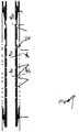
FIG. 1 is a section view of an embodiment with a proppant control shroud shown in the run in position; -
FIG. 2 is the view ofFIG. 1 with a valve open for proppant deposition and fracturing; -
FIG. 3 is the view ofFIG. 2 with the frac valve closed and the production valve open with a screen in the flow path of the production valve; -
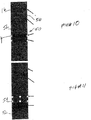
FIG. 4 is the view ofFIG. 1 but with an alternative embodiment where the proppant shroud straddles the production valve; -
FIG. 5 is the view ofFIG. 4 with the fracture and proppant deposition valve open; -
FIG. 6 is the view ofFIG. 5 with the fracture and proppant deposition valve closed and the production valve open with a screen in the flow path; -
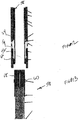
FIG. 7 is an alternative embodiment with no external proppant shroud and instead having a sleeve to open multiple production ports with screened openings and a frac valve all shown in a closed position for run in; -
FIG. 8 is the view ofFIG. 7 with the frac valve in the wide open fracturing position; -
FIG. 9 is the view ofFIG. 8 with the frac valve closed and the production sliding sleeve in the open position; -
FIG. 10 is a view of a frac valve in the closed position; -
FIG. 11 is the view ofFIG. 10 with the frac valve in the open position; -
FIG. 12 is the view ofFIG. 11 with the frac valve in the open position and an insertable screen in position for production; -
FIG. 13 is the view of the insertable screen shown inFIG. 12 ; -
FIG. 1 is a schematic illustration of awellbore 10 that can be cased or in open hole. There areperforations 12 into aformation 14. Astring 16 is shown in part ifFIG. 1 to the extent it spans a production interval defined between seals orpackers barriers production interval 22. While only one interval is shown thestring 16 can pass through multiple intervals that preferably have similar equipment so that access to them can occur in any desired order and access can be to one interval at a time or multiple intervals together. - The
string 16 for theinterval 22 that is illustrated has afrac valve 24 that is preferably a sliding sleeve shown in the closed position inFIG. 1 for run in. Valve 24 regulates opening oropenings 25 and is used in two positions. The closed position is shown inFIG. 1 and the wide open position is shown inFIG. 2 . In theFIG. 2 position, gravel slurry can be squeezed into theformation 14 leaving thegravel 28 in theannular interval 22 just outside the proppant screen orshroud 29.Shroud 29 is sealed on opposite ends 30 and 32 and in between defines anannular flow area 34. While theshroud 29 is shown as one continuous unit, it can also be segmented with discrete or interconnected segments. Theproppant 28 stays in theinterval 22 and the carrier fluid is pumped into theformation 14 to complete the fracturing operation. At that point thevalve 24 is closed andexcess proppant 28 that is still in thestring 16 can be circulated out to the surface using, for example,coiled tubing 36. - At this point the
production valve 26 which is preferably a sliding sleeve with ascreen material 38 in or over its ports is brought into alignment withports 40 and production from theformation 14 begins. Alternatively, thescreen material 38 can be fixed to either side of thestring 16. In short, the open position ofproduction valve 26 results in the production flow being screened regardless of screen position and screen type. Flow can take a path of less resistance through theflow area 34 to reach theport 40. While such flow avoids most of thegravel pack 28 by design, the presence ofpassage 34 allows a greater flow to reach theports 40 so as not to impede production. The presence of ascreen material 38 atports 40 serves to exclude solids that may have gotten intopassage 34 through the coarse openings inshroud 29. Thescreen material 38 can be of a variety of designs such as a weave, conjoined spheres, porous sintered metal or equivalent designs that perform the function of a screen to keepgravel 28 out of the flow passage throughstring 16. - It should be noted that while only a
single port valves valves barriers valves -
FIGS. 4-6 correspond toFIGS. 1-3 with the only difference being theshroud 29 having anend 32 that is past theopenings 40 so that thepassage 34 goes directly to theports 40. Here, as opposed toFIGS. 1-3 , once the flow from theformation 14 passes through theshroud 29 it doesn't have to pass through that shroud 29 a second time. In all other respects the method is the same. InFIG. 4 thevalves string 16 is in position and thebarriers valve 24 is opened, as shown inFIG. 5 , andproppant slurry 28 is delivered throughports 25. There is no crossover needed. When the proper amount of proppant is deposited in theinterval 22, thevalve 24 is closed andvalve 26 is opened to place thescreen material 38 overopenings 40 to let production begin. As before, with the design ofFIGS. 1-3 and the variations described for those FIGS., the same options are available to the alternative design ofFIGS. 4-6 . One advantage of the design inFIGS. 4-6 is that there is less resistance to flow inpassage 34 because of the avoidance of going through the shroud 29 a second time to get to theports 40. On the other hand, one of the advantages of the design ofFIGS. 1-3 is that the inside dimension of thestring 16 in the region close tovalve 26 can be larger because theshroud 29 terminates atend 32 well below theports 40. - In both designs the length of
shroud 29 can span many pipe joints and can exceed hundreds if not thousands of feet depending on the length of theinterval 22. Those skilled in the art will appreciate that short jumper sections can be used to cover the connections after assembly so that thepassage 34 winds up being continuous. -
FIGS. 7-9 work similarly toFIGS. 1-3 with the only design difference being that theshroud 29 is not used because the application for this design is for rather short intervals where a bypass passage such as 34 around ashroud 29 is not necessary to get the desired production flow rates. Insteadvalve 26 has a plurality ofscreen sections 38 that can be aligned with axially spaced arrays ofopenings 40. In this case as with the other designs, thevalves tubular string 16. In all other ways, the operation of the embodiment ofFIGS. 7-9 is the same asFIGS. 1-3 . InFIG. 7 for run in thevalves string 16 is placed in position andbarriers zone 22. InFIG. 8 , thevalve 24 is opened and thegravel slurry 28 is squeezed into theformation 14 leaving the gravel in theinterval 22 outside ofopenings 40. InFIG. 9 the gravel packing and frac is completed and thevalve 24 is closed. Thenvalve 26 is opened placingscreen material 38 in front ofopenings 40 and production can begin. In essence,valve 26 with itsscreen sections 38 andopenings 40 act as a screen that is blocked for run in and gravel deposition and frac and then functions as a screen for production. Again multiple assemblies ofvalves screen sections 38 clog up, another section can be placed in service to continue production. -
FIG. 10 , which is not part of the present invention, illustrates a valve 50 that uses a slidingsleeve 52 to selectively cover ports 54. The ports 54 are closed inFIG. 10 and open inFIG. 11 . Alatch profile 56 is provided adjacent eachsleeve 52. An array of valves 50 and associated ports 54 is envisioned. The configuration of thelatch profile 56 is preferably unique so as to accept aspecific screen assembly 58, one of which is shown inFIG. 13 . Each screen assembly has a latch 60 that is uniquely matched to aprofile 56.FIG. 12 shows ascreen assembly 58 that has a latch 60 engaged in itsmating profile 56. In that position a screen 62 has end seals 64 and 66 that straddle ports 54 withsleeve 52 disposed to uncover the ports 54. One or more such assemblies are envisioned in aninterval 22 betweenisolators FIG. 10 . After getting thestring 16 into position and setting the barriers (not shown inFIG. 10 ) to define aninterval 22, as before, the ports 54 are exposed and gravel slurry is forced into the formation as the formation is fractured. At this time thescreen assembly 58 is not instring 16. When that step is done and the excess slurry is circulated out, the valves 50 to be used in production are opened. Ascreen assembly 58 with a latch 60 that matches the valve or valves 50 just opened is delivered into thestring 16 and secured to its associatedprofile 56. In this manner, the ports 54 that are now open each receive ascreen assembly 58 and production can begin. Any order of producing multiple intervals can be established. Thescreen sections 58 can be dropped in or lowered in on wireline or other means. They are designed to release with an upward pull so if they clog during production they can be released fromlatch 56 and removed and replaced to allow production to resume. The screen assemblies can have afishing neck 68 to be used with known fishing tools to retrieve thescreen section 58 to the surface. One screen section can cover one array of ports 54 or multiple arrays, depending on its length and the spacing between seals 64 and 66. - The above description is illustrative of the preferred embodiment and many modifications may be made by those skilled in the art without departing from the invention whose scope is to be determined from the literal and equivalent scope of the claims below.
Claims (11)
- A completion assembly for a zone in a subterranean location, comprising:a tubular housing (16) defining a wall;at least one first valved port (25) in said wall, wherein the at least one first valved port (25) comprises a first sliding sleeve valve (24) with a first sliding sleeve that is selectively movable between a closed and an open position, wherein said first valved port (25) is substantially unobstructed; andat least one second valved port (40) in said wall,wherein the at least one second valved port (40) comprises a second sliding sleeve valve (26) with a second sliding sleeve that is movable between a fully closed and an open position where flow through said second valved port (40) is screened, wherein said second sliding sleeve comprises a screen (38) that is brought into alignment with the port (40) in the open position, and wherein the first sliding sleeve and the second sliding sleeve are each axially shiftable or rotatable with respect to said wall.
- The assembly of claim 1, wherein said wall comprises an outer surface and at least one porous shroud (29) mounted to it that defines an annular passage (34) about said outer surface of said wall.
- The assembly of claim 2, wherein said shroud (29) spans over at least one said second valved port (40).
- The assembly of claim 2, wherein said passage (34) is sealed at opposed ends to said outer surface.
- The assembly of claim 1, wherein said second sliding sleeve valve (26) comprises a plurality of ports on its sliding sleeve that each can be aligned in tandem to second valved ports (40) in said wall such that flow through the aligned ports is screened.
- A completion method, comprising:delivering a tubular housing (16) defining a wall and having at least one first valved port (25) and at least one second valved port (40) to a desired location downhole, wherein the at least one first valved port (25) is provided with a first sliding sleeve (24) that is selectively movable between a closed and an open position, where said first valved port (25) is substantially unobstructed, and wherein the at least one second valved port (40) is provided with a second sliding sleeve (26) having a screen (38) that is movable between a fully closed and an open position, where flow through said second valved port (40) is screened, wherein the first sliding sleeve (24) and the second sliding sleeve (26) are each axially shiftable or rotatable with respect to said wall;performing a downhole operation through said first valved port (25) when it is open;closing said first valved port (25) after said performing of downhole operation;opening said second valved port (40), after closing said first valved port (25), in a manner to allow production flow into said housing (16) to pass the screen (38) of the second sliding sleeve (26).
- The method of claim 6, comprising: performing a gravel pack (28) and formation fracture as said downhole operation.
- The method of claim 7, comprising:providing at least one porous shroud (29) around said housing (16) to define a flow passage (34) around said housing (16);depositing said gravel (28) outside said shroud (29); andtaking production flow through said passage (34) inside screen (38) and toward said screen (38) associated with said second valved port (40).
- The method of claim 8, comprising:sealing said passage (34) to said housing (16) on opposed ends (30, 32) of said shroud (29); andpositioning said shroud (29) offset from said second valved port (40).
- The method of claim 8, comprising:sealing said passage (34) to said housing (16) on opposed ends (30, 32) of said shroud (29); andpositioning said shroud (29) over at least one said second valved port (40).
- The method of claim 7, comprising: sealing said housing (16) in the wellbore to isolate at least one producing zone having at least one set of first and second valved ports (25, 40) therein.
Applications Claiming Priority (2)
| Application Number | Priority Date | Filing Date | Title |
|---|---|---|---|
| US11/949,403 US8127847B2 (en) | 2007-12-03 | 2007-12-03 | Multi-position valves for fracturing and sand control and associated completion methods |
| PCT/US2008/084271 WO2009073391A2 (en) | 2007-12-03 | 2008-11-21 | Multi-position valves for fracturing and sand control associated completion methods |
Publications (3)
| Publication Number | Publication Date |
|---|---|
| EP2222936A2 EP2222936A2 (en) | 2010-09-01 |
| EP2222936A4 EP2222936A4 (en) | 2012-06-13 |
| EP2222936B1 true EP2222936B1 (en) | 2021-04-28 |
Family
ID=40674562
Family Applications (1)
| Application Number | Title | Priority Date | Filing Date |
|---|---|---|---|
| EP08857887.7A Active EP2222936B1 (en) | 2007-12-03 | 2008-11-21 | Multi-position valves for fracturing and sand control associated completion methods |
Country Status (6)
| Country | Link |
|---|---|
| US (2) | US8127847B2 (en) |
| EP (1) | EP2222936B1 (en) |
| CN (2) | CN102817583B (en) |
| BR (1) | BRPI0819995B1 (en) |
| CA (1) | CA2707480A1 (en) |
| WO (1) | WO2009073391A2 (en) |
Families Citing this family (46)
| Publication number | Priority date | Publication date | Assignee | Title |
|---|---|---|---|---|
| US7971646B2 (en) * | 2007-08-16 | 2011-07-05 | Baker Hughes Incorporated | Multi-position valve for fracturing and sand control and associated completion methods |
| US7775271B2 (en) | 2007-10-19 | 2010-08-17 | Baker Hughes Incorporated | Device and system for well completion and control and method for completing and controlling a well |
| US7784543B2 (en) * | 2007-10-19 | 2010-08-31 | Baker Hughes Incorporated | Device and system for well completion and control and method for completing and controlling a well |
| US7913755B2 (en) | 2007-10-19 | 2011-03-29 | Baker Hughes Incorporated | Device and system for well completion and control and method for completing and controlling a well |
| US7789139B2 (en) | 2007-10-19 | 2010-09-07 | Baker Hughes Incorporated | Device and system for well completion and control and method for completing and controlling a well |
| US7775277B2 (en) * | 2007-10-19 | 2010-08-17 | Baker Hughes Incorporated | Device and system for well completion and control and method for completing and controlling a well |
| US7793714B2 (en) | 2007-10-19 | 2010-09-14 | Baker Hughes Incorporated | Device and system for well completion and control and method for completing and controlling a well |
| US7934553B2 (en) * | 2008-04-21 | 2011-05-03 | Schlumberger Technology Corporation | Method for controlling placement and flow at multiple gravel pack zones in a wellbore |
| US8171999B2 (en) * | 2008-05-13 | 2012-05-08 | Baker Huges Incorporated | Downhole flow control device and method |
| US8555958B2 (en) * | 2008-05-13 | 2013-10-15 | Baker Hughes Incorporated | Pipeless steam assisted gravity drainage system and method |
| US8113292B2 (en) | 2008-05-13 | 2012-02-14 | Baker Hughes Incorporated | Strokable liner hanger and method |
| US7814981B2 (en) * | 2008-08-26 | 2010-10-19 | Baker Hughes Incorporated | Fracture valve and equalizer system and method |
| US9194217B2 (en) * | 2009-05-27 | 2015-11-24 | Schlumberger Technology Corporation | Method and system of sand management |
| US20100300675A1 (en) * | 2009-06-02 | 2010-12-02 | Baker Hughes Incorporated | Permeability flow balancing within integral screen joints |
| US8132624B2 (en) * | 2009-06-02 | 2012-03-13 | Baker Hughes Incorporated | Permeability flow balancing within integral screen joints and method |
| US20100300674A1 (en) * | 2009-06-02 | 2010-12-02 | Baker Hughes Incorporated | Permeability flow balancing within integral screen joints |
| US8151881B2 (en) * | 2009-06-02 | 2012-04-10 | Baker Hughes Incorporated | Permeability flow balancing within integral screen joints |
| US8056627B2 (en) * | 2009-06-02 | 2011-11-15 | Baker Hughes Incorporated | Permeability flow balancing within integral screen joints and method |
| CA2785713C (en) | 2010-01-04 | 2018-02-27 | Packers Plus Energy Services Inc. | Wellbore treatment apparatus and method |
| BR112013008040A2 (en) | 2010-09-22 | 2016-06-14 | Packers Plus Energy Serv Inc | well wall hydraulic fracturing tool with inlet flow control field |
| US9797221B2 (en) | 2010-09-23 | 2017-10-24 | Packers Plus Energy Services Inc. | Apparatus and method for fluid treatment of a well |
| AU2011331867A1 (en) | 2010-11-19 | 2013-06-06 | Packers Plus Energy Services Inc. | Kobe sub, wellbore tubing string apparatus and method |
| US20140224471A1 (en) * | 2011-09-12 | 2014-08-14 | Packers Plus Energy Services Inc. | Wellbore frac tool with inflow control |
| CN103573226B (en) * | 2012-07-24 | 2016-03-02 | 思达斯易能源技术(集团)有限公司 | A kind of completion and sand control technique and sand control pipe thereof |
| CN103015952B (en) * | 2012-12-12 | 2015-07-15 | 山东瑞丰石油技术有限责任公司 | Method for packing multiple layers of gravel in one time |
| US10830028B2 (en) | 2013-02-07 | 2020-11-10 | Baker Hughes Holdings Llc | Frac optimization using ICD technology |
| US9617836B2 (en) | 2013-08-23 | 2017-04-11 | Baker Hughes Incorporated | Passive in-flow control devices and methods for using same |
| CN103821476A (en) * | 2014-03-14 | 2014-05-28 | 胡和萍 | Fixing valve |
| US9759057B2 (en) | 2014-04-11 | 2017-09-12 | Dynacorp Fabricators Inc. | Apparatus, system and method for separating sand and other solids from oil and other fluids |
| US10180046B2 (en) | 2014-12-23 | 2019-01-15 | Ncs Multistage Inc. | Downhole flow control apparatus with screen |
| US10487630B2 (en) * | 2015-03-06 | 2019-11-26 | Halliburton Energy Services, Inc. | High flow injection screen system with sleeves |
| CN104775802B (en) * | 2015-03-26 | 2017-02-22 | 中国石油化工股份有限公司 | Separate-layer fracturing sand control string for thermal production well and sand control method thereof |
| CN104929603B (en) * | 2015-06-05 | 2017-07-11 | 中国石油集团渤海钻探工程有限公司 | Sleeve pipe infinite stages staged fracturing method |
| US10184316B2 (en) | 2015-09-03 | 2019-01-22 | Baker Hughes, A Ge Company, Llc | Three position interventionless treatment and production valve assembly |
| CA2965068C (en) | 2016-04-22 | 2023-11-14 | Ncs Multistage Inc. | Apparatus, systems and methods for controlling flow communication with a subterranean formation |
| GB2595365B (en) | 2016-05-03 | 2022-03-09 | Darcy Tech Limited | Downhole apparatus |
| DK3513031T3 (en) | 2016-09-16 | 2021-08-02 | Ncs Multistage Inc | WELL DRILLING FLOW CONTROLLER WITH SOLID CONTROL |
| US10294754B2 (en) | 2017-03-16 | 2019-05-21 | Baker Hughes, A Ge Company, Llc | Re-closable coil activated frack sleeve |
| CN109958417A (en) * | 2017-12-26 | 2019-07-02 | 中国石油天然气股份有限公司 | Fracturing sand control tubing string and method |
| CN108518203B (en) * | 2018-03-16 | 2020-07-07 | 大连坤麟金属制品有限公司 | Rotary oil production facility integration |
| CA3104205C (en) | 2018-09-06 | 2023-03-21 | Halliburton Energy Services, Inc. | A multi-functional sleeve completion system with return and reverse fluid path |
| EP3935261A4 (en) * | 2019-03-08 | 2022-08-10 | NCS Multistage Inc. | Downhole flow controller |
| US11333002B2 (en) | 2020-01-29 | 2022-05-17 | Halliburton Energy Services, Inc. | Completion systems and methods to perform completion operations |
| US11261674B2 (en) | 2020-01-29 | 2022-03-01 | Halliburton Energy Services, Inc. | Completion systems and methods to perform completion operations |
| CA3191573A1 (en) * | 2020-12-18 | 2022-06-23 | Halliburton Energy Services, Inc. | Production valve having washpipe free activation |
| CN112901131B (en) * | 2021-02-20 | 2022-07-22 | 中海油能源发展股份有限公司 | Staged fracturing process pipe column for loose sandstone in-service screen pipe sand-prevention horizontal well and operation method |
Family Cites Families (26)
| Publication number | Priority date | Publication date | Assignee | Title |
|---|---|---|---|---|
| US4969524A (en) * | 1989-10-17 | 1990-11-13 | Halliburton Company | Well completion assembly |
| US5295538A (en) * | 1992-07-29 | 1994-03-22 | Halliburton Company | Sintered screen completion |
| US5333688A (en) * | 1993-01-07 | 1994-08-02 | Mobil Oil Corporation | Method and apparatus for gravel packing of wells |
| US5875852A (en) * | 1997-02-04 | 1999-03-02 | Halliburton Energy Services, Inc. | Apparatus and associated methods of producing a subterranean well |
| US5971070A (en) * | 1997-08-27 | 1999-10-26 | Halliburton Energy Services, Inc. | Apparatus for completing a subterranean well and associated methods |
| US6176307B1 (en) * | 1999-02-08 | 2001-01-23 | Union Oil Company Of California | Tubing-conveyed gravel packing tool and method |
| US6644406B1 (en) * | 2000-07-31 | 2003-11-11 | Mobil Oil Corporation | Fracturing different levels within a completion interval of a well |
| US7096945B2 (en) * | 2002-01-25 | 2006-08-29 | Halliburton Energy Services, Inc. | Sand control screen assembly and treatment method using the same |
| US6675893B2 (en) * | 2002-06-17 | 2004-01-13 | Conocophillips Company | Single placement well completion system |
| US7644773B2 (en) * | 2002-08-23 | 2010-01-12 | Baker Hughes Incorporated | Self-conforming screen |
| US6978840B2 (en) * | 2003-02-05 | 2005-12-27 | Halliburton Energy Services, Inc. | Well screen assembly and system with controllable variable flow area and method of using same for oil well fluid production |
| US7066265B2 (en) * | 2003-09-24 | 2006-06-27 | Halliburton Energy Services, Inc. | System and method of production enhancement and completion of a well |
| US7461699B2 (en) * | 2003-10-22 | 2008-12-09 | Baker Hughes Incorporated | Method for providing a temporary barrier in a flow pathway |
| US8342240B2 (en) * | 2003-10-22 | 2013-01-01 | Baker Hughes Incorporated | Method for providing a temporary barrier in a flow pathway |
| US7316274B2 (en) * | 2004-03-05 | 2008-01-08 | Baker Hughes Incorporated | One trip perforating, cementing, and sand management apparatus and method |
| WO2005056979A1 (en) * | 2003-12-08 | 2005-06-23 | Baker Hughes Incorporated | Cased hole perforating alternative |
| US7401648B2 (en) * | 2004-06-14 | 2008-07-22 | Baker Hughes Incorporated | One trip well apparatus with sand control |
| US7185703B2 (en) * | 2004-06-18 | 2007-03-06 | Halliburton Energy Services, Inc. | Downhole completion system and method for completing a well |
| US20090084553A1 (en) * | 2004-12-14 | 2009-04-02 | Schlumberger Technology Corporation | Sliding sleeve valve assembly with sand screen |
| US7387165B2 (en) * | 2004-12-14 | 2008-06-17 | Schlumberger Technology Corporation | System for completing multiple well intervals |
| US7575062B2 (en) * | 2006-06-09 | 2009-08-18 | Halliburton Energy Services, Inc. | Methods and devices for treating multiple-interval well bores |
| WO2009023611A2 (en) * | 2007-08-13 | 2009-02-19 | Baker Hughes Incorporated | Multi-position valve for fracturing and sand control and associated completion methods |
| US7971646B2 (en) * | 2007-08-16 | 2011-07-05 | Baker Hughes Incorporated | Multi-position valve for fracturing and sand control and associated completion methods |
| US7703510B2 (en) * | 2007-08-27 | 2010-04-27 | Baker Hughes Incorporated | Interventionless multi-position frac tool |
| US8096351B2 (en) * | 2007-10-19 | 2012-01-17 | Baker Hughes Incorporated | Water sensing adaptable in-flow control device and method of use |
| US7708073B2 (en) * | 2008-03-05 | 2010-05-04 | Baker Hughes Incorporated | Heat generator for screen deployment |
-
2007
- 2007-12-03 US US11/949,403 patent/US8127847B2/en active Active
-
2008
- 2008-11-21 CN CN201210344178.9A patent/CN102817583B/en active Active
- 2008-11-21 EP EP08857887.7A patent/EP2222936B1/en active Active
- 2008-11-21 CN CN200880123492.6A patent/CN101910550B/en active Active
- 2008-11-21 WO PCT/US2008/084271 patent/WO2009073391A2/en active Application Filing
- 2008-11-21 CA CA2707480A patent/CA2707480A1/en not_active Abandoned
- 2008-11-21 BR BRPI0819995A patent/BRPI0819995B1/en active IP Right Grant
-
2011
- 2011-12-13 US US13/324,450 patent/US8342245B2/en active Active
Non-Patent Citations (1)
| Title |
|---|
| None * |
Also Published As
| Publication number | Publication date |
|---|---|
| BRPI0819995A2 (en) | 2015-05-12 |
| EP2222936A4 (en) | 2012-06-13 |
| US8127847B2 (en) | 2012-03-06 |
| WO2009073391A3 (en) | 2009-08-27 |
| US8342245B2 (en) | 2013-01-01 |
| WO2009073391A2 (en) | 2009-06-11 |
| CA2707480A1 (en) | 2009-06-11 |
| BRPI0819995B1 (en) | 2018-10-23 |
| US20120080188A1 (en) | 2012-04-05 |
| CN101910550B (en) | 2014-08-13 |
| CN101910550A (en) | 2010-12-08 |
| CN102817583B (en) | 2016-04-20 |
| US20090139717A1 (en) | 2009-06-04 |
| CN102817583A (en) | 2012-12-12 |
| EP2222936A2 (en) | 2010-09-01 |
Similar Documents
| Publication | Publication Date | Title |
|---|---|---|
| EP2222936B1 (en) | Multi-position valves for fracturing and sand control associated completion methods | |
| US8245782B2 (en) | Tool and method of performing rigless sand control in multiple zones | |
| US8291982B2 (en) | Multi-position valve for fracturing and sand control and associated completion methods | |
| US6488082B2 (en) | Remotely operated multi-zone packing system | |
| US6446729B1 (en) | Sand control method and apparatus | |
| US7591312B2 (en) | Completion method for fracturing and gravel packing | |
| US7857061B2 (en) | Flow control in a well bore | |
| US7290610B2 (en) | Washpipeless frac pack system | |
| US8267173B2 (en) | Open hole completion apparatus and method for use of same | |
| US9677387B2 (en) | Screen assembly | |
| US20050039917A1 (en) | Isolation packer inflated by a fluid filtered from a gravel laden slurry | |
| AU2009214444A2 (en) | Valve apparatus for inflow control | |
| AU2008287022B2 (en) | Multi-position valve for fracturing and sand control and associated completion methods | |
| US10941640B2 (en) | Multi-functional sleeve completion system with return and reverse fluid path | |
| AU2013258831B2 (en) | Multi-position valve for fracturing and sand control |
Legal Events
| Date | Code | Title | Description |
|---|---|---|---|
| PUAI | Public reference made under article 153(3) epc to a published international application that has entered the european phase |
Free format text: ORIGINAL CODE: 0009012 |
|
| 17P | Request for examination filed |
Effective date: 20100621 |
|
| AK | Designated contracting states |
Kind code of ref document: A2 Designated state(s): AT BE BG CH CY CZ DE DK EE ES FI FR GB GR HR HU IE IS IT LI LT LU LV MC MT NL NO PL PT RO SE SI SK TR |
|
| AX | Request for extension of the european patent |
Extension state: AL BA MK RS |
|
| DAX | Request for extension of the european patent (deleted) | ||
| A4 | Supplementary search report drawn up and despatched |
Effective date: 20120515 |
|
| RIC1 | Information provided on ipc code assigned before grant |
Ipc: E21B 34/08 20060101ALI20120509BHEP Ipc: E21B 43/08 20060101ALI20120509BHEP Ipc: E21B 34/16 20060101AFI20120509BHEP Ipc: E21B 43/26 20060101ALI20120509BHEP Ipc: E21B 34/06 20060101ALI20120509BHEP |
|
| 17Q | First examination report despatched |
Effective date: 20130129 |
|
| STAA | Information on the status of an ep patent application or granted ep patent |
Free format text: STATUS: EXAMINATION IS IN PROGRESS |
|
| GRAP | Despatch of communication of intention to grant a patent |
Free format text: ORIGINAL CODE: EPIDOSNIGR1 |
|
| STAA | Information on the status of an ep patent application or granted ep patent |
Free format text: STATUS: GRANT OF PATENT IS INTENDED |
|
| INTG | Intention to grant announced |
Effective date: 20200803 |
|
| GRAS | Grant fee paid |
Free format text: ORIGINAL CODE: EPIDOSNIGR3 |
|
| STAA | Information on the status of an ep patent application or granted ep patent |
Free format text: STATUS: GRANT OF PATENT IS INTENDED |
|
| GRAA | (expected) grant |
Free format text: ORIGINAL CODE: 0009210 |
|
| STAA | Information on the status of an ep patent application or granted ep patent |
Free format text: STATUS: THE PATENT HAS BEEN GRANTED |
|
| RIN1 | Information on inventor provided before grant (corrected) |
Inventor name: RICHARD, BENNETT Inventor name: FAY, PETER J. Inventor name: JOHNSON, MICHAEL H. |
|
| RAP3 | Party data changed (applicant data changed or rights of an application transferred) |
Owner name: BAKER HUGHES HOLDINGS LLC |
|
| AK | Designated contracting states |
Kind code of ref document: B1 Designated state(s): AT BE BG CH CY CZ DE DK EE ES FI FR GB GR HR HU IE IS IT LI LT LU LV MC MT NL NO PL PT RO SE SI SK TR |
|
| REG | Reference to a national code |
Ref country code: GB Ref legal event code: FG4D |
|
| REG | Reference to a national code |
Ref country code: CH Ref legal event code: EP |
|
| REG | Reference to a national code |
Ref country code: DE Ref legal event code: R096 Ref document number: 602008063912 Country of ref document: DE |
|
| REG | Reference to a national code |
Ref country code: AT Ref legal event code: REF Ref document number: 1387237 Country of ref document: AT Kind code of ref document: T Effective date: 20210515 |
|
| REG | Reference to a national code |
Ref country code: IE Ref legal event code: FG4D |
|
| REG | Reference to a national code |
Ref country code: LT Ref legal event code: MG9D |
|
| REG | Reference to a national code |
Ref country code: NO Ref legal event code: T2 Effective date: 20210428 |
|
| REG | Reference to a national code |
Ref country code: AT Ref legal event code: MK05 Ref document number: 1387237 Country of ref document: AT Kind code of ref document: T Effective date: 20210428 |
|
| PG25 | Lapsed in a contracting state [announced via postgrant information from national office to epo] |
Ref country code: BG Free format text: LAPSE BECAUSE OF FAILURE TO SUBMIT A TRANSLATION OF THE DESCRIPTION OR TO PAY THE FEE WITHIN THE PRESCRIBED TIME-LIMIT Effective date: 20210728 Ref country code: AT Free format text: LAPSE BECAUSE OF FAILURE TO SUBMIT A TRANSLATION OF THE DESCRIPTION OR TO PAY THE FEE WITHIN THE PRESCRIBED TIME-LIMIT Effective date: 20210428 Ref country code: HR Free format text: LAPSE BECAUSE OF FAILURE TO SUBMIT A TRANSLATION OF THE DESCRIPTION OR TO PAY THE FEE WITHIN THE PRESCRIBED TIME-LIMIT Effective date: 20210428 Ref country code: NL Free format text: LAPSE BECAUSE OF FAILURE TO SUBMIT A TRANSLATION OF THE DESCRIPTION OR TO PAY THE FEE WITHIN THE PRESCRIBED TIME-LIMIT Effective date: 20210428 Ref country code: LT Free format text: LAPSE BECAUSE OF FAILURE TO SUBMIT A TRANSLATION OF THE DESCRIPTION OR TO PAY THE FEE WITHIN THE PRESCRIBED TIME-LIMIT Effective date: 20210428 Ref country code: FI Free format text: LAPSE BECAUSE OF FAILURE TO SUBMIT A TRANSLATION OF THE DESCRIPTION OR TO PAY THE FEE WITHIN THE PRESCRIBED TIME-LIMIT Effective date: 20210428 |
|
| PG25 | Lapsed in a contracting state [announced via postgrant information from national office to epo] |
Ref country code: ES Free format text: LAPSE BECAUSE OF FAILURE TO SUBMIT A TRANSLATION OF THE DESCRIPTION OR TO PAY THE FEE WITHIN THE PRESCRIBED TIME-LIMIT Effective date: 20210428 Ref country code: PT Free format text: LAPSE BECAUSE OF FAILURE TO SUBMIT A TRANSLATION OF THE DESCRIPTION OR TO PAY THE FEE WITHIN THE PRESCRIBED TIME-LIMIT Effective date: 20210830 Ref country code: PL Free format text: LAPSE BECAUSE OF FAILURE TO SUBMIT A TRANSLATION OF THE DESCRIPTION OR TO PAY THE FEE WITHIN THE PRESCRIBED TIME-LIMIT Effective date: 20210428 Ref country code: IS Free format text: LAPSE BECAUSE OF FAILURE TO SUBMIT A TRANSLATION OF THE DESCRIPTION OR TO PAY THE FEE WITHIN THE PRESCRIBED TIME-LIMIT Effective date: 20210828 Ref country code: LV Free format text: LAPSE BECAUSE OF FAILURE TO SUBMIT A TRANSLATION OF THE DESCRIPTION OR TO PAY THE FEE WITHIN THE PRESCRIBED TIME-LIMIT Effective date: 20210428 Ref country code: GR Free format text: LAPSE BECAUSE OF FAILURE TO SUBMIT A TRANSLATION OF THE DESCRIPTION OR TO PAY THE FEE WITHIN THE PRESCRIBED TIME-LIMIT Effective date: 20210729 Ref country code: SE Free format text: LAPSE BECAUSE OF FAILURE TO SUBMIT A TRANSLATION OF THE DESCRIPTION OR TO PAY THE FEE WITHIN THE PRESCRIBED TIME-LIMIT Effective date: 20210428 |
|
| REG | Reference to a national code |
Ref country code: NL Ref legal event code: MP Effective date: 20210428 |
|
| PG25 | Lapsed in a contracting state [announced via postgrant information from national office to epo] |
Ref country code: EE Free format text: LAPSE BECAUSE OF FAILURE TO SUBMIT A TRANSLATION OF THE DESCRIPTION OR TO PAY THE FEE WITHIN THE PRESCRIBED TIME-LIMIT Effective date: 20210428 Ref country code: DK Free format text: LAPSE BECAUSE OF FAILURE TO SUBMIT A TRANSLATION OF THE DESCRIPTION OR TO PAY THE FEE WITHIN THE PRESCRIBED TIME-LIMIT Effective date: 20210428 Ref country code: CZ Free format text: LAPSE BECAUSE OF FAILURE TO SUBMIT A TRANSLATION OF THE DESCRIPTION OR TO PAY THE FEE WITHIN THE PRESCRIBED TIME-LIMIT Effective date: 20210428 Ref country code: SK Free format text: LAPSE BECAUSE OF FAILURE TO SUBMIT A TRANSLATION OF THE DESCRIPTION OR TO PAY THE FEE WITHIN THE PRESCRIBED TIME-LIMIT Effective date: 20210428 Ref country code: RO Free format text: LAPSE BECAUSE OF FAILURE TO SUBMIT A TRANSLATION OF THE DESCRIPTION OR TO PAY THE FEE WITHIN THE PRESCRIBED TIME-LIMIT Effective date: 20210428 |
|
| REG | Reference to a national code |
Ref country code: DE Ref legal event code: R097 Ref document number: 602008063912 Country of ref document: DE |
|
| PLBE | No opposition filed within time limit |
Free format text: ORIGINAL CODE: 0009261 |
|
| STAA | Information on the status of an ep patent application or granted ep patent |
Free format text: STATUS: NO OPPOSITION FILED WITHIN TIME LIMIT |
|
| 26N | No opposition filed |
Effective date: 20220131 |
|
| PG25 | Lapsed in a contracting state [announced via postgrant information from national office to epo] |
Ref country code: IS Free format text: LAPSE BECAUSE OF FAILURE TO SUBMIT A TRANSLATION OF THE DESCRIPTION OR TO PAY THE FEE WITHIN THE PRESCRIBED TIME-LIMIT Effective date: 20210828 |
|
| REG | Reference to a national code |
Ref country code: DE Ref legal event code: R119 Ref document number: 602008063912 Country of ref document: DE |
|
| PG25 | Lapsed in a contracting state [announced via postgrant information from national office to epo] |
Ref country code: MC Free format text: LAPSE BECAUSE OF FAILURE TO SUBMIT A TRANSLATION OF THE DESCRIPTION OR TO PAY THE FEE WITHIN THE PRESCRIBED TIME-LIMIT Effective date: 20210428 |
|
| REG | Reference to a national code |
Ref country code: CH Ref legal event code: PL |
|
| PG25 | Lapsed in a contracting state [announced via postgrant information from national office to epo] |
Ref country code: LU Free format text: LAPSE BECAUSE OF NON-PAYMENT OF DUE FEES Effective date: 20211121 Ref country code: IT Free format text: LAPSE BECAUSE OF FAILURE TO SUBMIT A TRANSLATION OF THE DESCRIPTION OR TO PAY THE FEE WITHIN THE PRESCRIBED TIME-LIMIT Effective date: 20210428 Ref country code: BE Free format text: LAPSE BECAUSE OF NON-PAYMENT OF DUE FEES Effective date: 20211130 |
|
| REG | Reference to a national code |
Ref country code: BE Ref legal event code: MM Effective date: 20211130 |
|
| PG25 | Lapsed in a contracting state [announced via postgrant information from national office to epo] |
Ref country code: LI Free format text: LAPSE BECAUSE OF NON-PAYMENT OF DUE FEES Effective date: 20211130 Ref country code: CH Free format text: LAPSE BECAUSE OF NON-PAYMENT OF DUE FEES Effective date: 20211130 |
|
| PG25 | Lapsed in a contracting state [announced via postgrant information from national office to epo] |
Ref country code: IE Free format text: LAPSE BECAUSE OF NON-PAYMENT OF DUE FEES Effective date: 20211121 Ref country code: DE Free format text: LAPSE BECAUSE OF NON-PAYMENT OF DUE FEES Effective date: 20220601 |
|
| PG25 | Lapsed in a contracting state [announced via postgrant information from national office to epo] |
Ref country code: FR Free format text: LAPSE BECAUSE OF NON-PAYMENT OF DUE FEES Effective date: 20211130 |
|
| PG25 | Lapsed in a contracting state [announced via postgrant information from national office to epo] |
Ref country code: HU Free format text: LAPSE BECAUSE OF FAILURE TO SUBMIT A TRANSLATION OF THE DESCRIPTION OR TO PAY THE FEE WITHIN THE PRESCRIBED TIME-LIMIT; INVALID AB INITIO Effective date: 20081121 Ref country code: CY Free format text: LAPSE BECAUSE OF FAILURE TO SUBMIT A TRANSLATION OF THE DESCRIPTION OR TO PAY THE FEE WITHIN THE PRESCRIBED TIME-LIMIT Effective date: 20210428 |
|
| P01 | Opt-out of the competence of the unified patent court (upc) registered |
Effective date: 20230526 |
|
| PGFP | Annual fee paid to national office [announced via postgrant information from national office to epo] |
Ref country code: GB Payment date: 20231019 Year of fee payment: 16 |
|
| PGFP | Annual fee paid to national office [announced via postgrant information from national office to epo] |
Ref country code: NO Payment date: 20231023 Year of fee payment: 16 |