EP2222500B1 - Child restraint apparatus for vehicle - Google Patents
Child restraint apparatus for vehicle Download PDFInfo
- Publication number
- EP2222500B1 EP2222500B1 EP08859468.4A EP08859468A EP2222500B1 EP 2222500 B1 EP2222500 B1 EP 2222500B1 EP 08859468 A EP08859468 A EP 08859468A EP 2222500 B1 EP2222500 B1 EP 2222500B1
- Authority
- EP
- European Patent Office
- Prior art keywords
- energy absorbing
- absorbing member
- child
- restraint apparatus
- child restraint
- Prior art date
- Legal status (The legal status is an assumption and is not a legal conclusion. Google has not performed a legal analysis and makes no representation as to the accuracy of the status listed.)
- Active
Links
Images



Classifications
-
- B—PERFORMING OPERATIONS; TRANSPORTING
- B60—VEHICLES IN GENERAL
- B60N—SEATS SPECIALLY ADAPTED FOR VEHICLES; VEHICLE PASSENGER ACCOMMODATION NOT OTHERWISE PROVIDED FOR
- B60N2/00—Seats specially adapted for vehicles; Arrangement or mounting of seats in vehicles
- B60N2/24—Seats specially adapted for vehicles; Arrangement or mounting of seats in vehicles for particular purposes or particular vehicles
- B60N2/26—Seats specially adapted for vehicles; Arrangement or mounting of seats in vehicles for particular purposes or particular vehicles for children
- B60N2/28—Seats readily mountable on, and dismountable from, existing seats or other parts of the vehicle
- B60N2/2884—Seats readily mountable on, and dismountable from, existing seats or other parts of the vehicle with protection systems against abnormal g-forces
-
- B—PERFORMING OPERATIONS; TRANSPORTING
- B60—VEHICLES IN GENERAL
- B60N—SEATS SPECIALLY ADAPTED FOR VEHICLES; VEHICLE PASSENGER ACCOMMODATION NOT OTHERWISE PROVIDED FOR
- B60N2/00—Seats specially adapted for vehicles; Arrangement or mounting of seats in vehicles
- B60N2/24—Seats specially adapted for vehicles; Arrangement or mounting of seats in vehicles for particular purposes or particular vehicles
- B60N2/26—Seats specially adapted for vehicles; Arrangement or mounting of seats in vehicles for particular purposes or particular vehicles for children
- B60N2/28—Seats readily mountable on, and dismountable from, existing seats or other parts of the vehicle
- B60N2/2881—Upholstery, padded or cushioned members therefor
-
- B—PERFORMING OPERATIONS; TRANSPORTING
- B60—VEHICLES IN GENERAL
- B60N—SEATS SPECIALLY ADAPTED FOR VEHICLES; VEHICLE PASSENGER ACCOMMODATION NOT OTHERWISE PROVIDED FOR
- B60N2/00—Seats specially adapted for vehicles; Arrangement or mounting of seats in vehicles
- B60N2/24—Seats specially adapted for vehicles; Arrangement or mounting of seats in vehicles for particular purposes or particular vehicles
- B60N2/42—Seats specially adapted for vehicles; Arrangement or mounting of seats in vehicles for particular purposes or particular vehicles the seat constructed to protect the occupant from the effect of abnormal g-forces, e.g. crash or safety seats
- B60N2/4207—Seats specially adapted for vehicles; Arrangement or mounting of seats in vehicles for particular purposes or particular vehicles the seat constructed to protect the occupant from the effect of abnormal g-forces, e.g. crash or safety seats characterised by the direction of the g-forces
- B60N2/4235—Seats specially adapted for vehicles; Arrangement or mounting of seats in vehicles for particular purposes or particular vehicles the seat constructed to protect the occupant from the effect of abnormal g-forces, e.g. crash or safety seats characterised by the direction of the g-forces transversal
Definitions
- the present invention relates to a child restraint apparatus for example a child car seat for use in a vehicle.
- the present invention concerns such apparatus for reducing the risk of injury to passengers present in the vehicle who are seated adjacent said child car seat in the event of a vehicle accident or the like.
- the child car seat is located on the rear seat of a vehicle and is attached or restrained to the vehicle seat using a connection which makes use of a standard vehicle seat belt or dedicated connection points such as lower anchors, top tethers or those of the Isofix type. That said, child car seats may also be located on a front passenger seat of a vehicle, in which case, the child car seat is usually attached using the front passenger seat belt.
- the seat area taken up by a child car seat typically extends over the at least the width of one of the rear seat cushions. As such, additional passengers are able to occupy the remaining rear vehicle seats, including the seat immediately adjacent the seat cushion occupied by the child car seat.
- child car seats typically comprise a seat portion, a back portion and a head portion to support the child or infant occupant.
- the child car seat may also comprise raised side portions, which serve to restrict transverse movement of the child in the child car seat.
- the seat, back, head and raised side portions are commonly formed of a plastics material.
- the child car seat thereby effectively provides a rigid protective shell or body which at least partially surrounds the occupant of the child car seat.
- the seat, back, head and side portions of the child car seat may be covered in foam or other suitable cushioning materials on their inner facing surfaces to provide both a soft comfortable support for the child or infant against the underlying harder rigid plastic surfaces, and furthermore to provide cushioning against the internal surfaces of the shell should the child car seat be subjected to a sudden acceleration or deceleration.
- the fixings of the child seat with the vehicle may as a result of sufficient forces from the vehicle impact, permit the child car seat to move to some degree in a direction substantially in line with the direction of the vehicle impact.
- the amount and direction of movement of the child car seat will depend on a number of factors including the magnitude and direction of vehicle impact and the fixing method employed.
- a passenger occupying a seat adjacent to the child car seat, for example the middle rear seat of the vehicle, may as a result be impacted by the child car seat as the child car seat moves. Consequently, a passenger sitting adjacent the child seat may themselves suffer injury to the side of their body, including the torso, arms and/or upper leg areas, depending on the shape of the child car seat and where precisely the child car seat impacts the passenger.
- the impact of the child car seat on the adjacent passenger may also cause a sudden deceleration to the child car seat.
- the side impact of the vehicle should however occur on the opposite side of the vehicle, i.e. when the child car seat is positioned furthest from the point of impact on the rear seat of a vehicle, then there is a risk that the adjacent passenger to the child car seat will in this instance move towards the child car seat. Again there is a risk that the adjacent passenger will be injured as a result of impact with the child car seat, for example injury to the pelvis.
- the impact of the adjacent passenger with the child car seat may also in turn result in the child car seat impacting with the interior side of the vehicle and causing further injuries to the occupant of the child car seat.
- Document US-B-7125073 discloses a child restraint apparatus having an energy absorbing member and a vent.
- the present invention seeks to overcome the aforementioned problems and seeks to reduce the likelihood of injury to a passenger sitting adjacent a child restraint such as a child car seat.
- the invention in one aspect provides a child restraint apparatus for restraining a child within a vehicle interior.
- the apparatus has a body comprising an internal area for receiving a child, and an energy absorbing member which, in use, extends over at least part of an external surface of the body and which faces away from the internal area.
- the energy absorbing member seeks to cushion an impact that may occur with a passenger adjacent the child restraint apparatus in the event of a crash and thereby reduce the likelihood of injury to the passenger.
- the energy absorbing member comprises a deformable chamber.
- a deformable chamber allows the energy absorbing member to be deflated allowing the child restraint apparatus to be more readily stored. The chamber then need only be deployed when the child restraint apparatus is installed in a vehicle.
- the deformable chamber has a vent, the vent being configured to allow controlled expulsion of air from the chamber on deformation thereof.
- the vent seeks to allow the dissipation of energy during impact with an adjacent passenger to be controlled.
- the chamber is provided with open cell foam.
- Open cell foam is a readily available material which may be easily formed to the required configuration and which provides resilient, controlled air release characteristics.
- the energy absorbing member comprises one or more resilient layers.
- layers may be provided each with different energy absorbing characteristics and thereby the properties of the energy absorbing member may be tailored to the particular application.
- the energy absorbing member comprises an air tight membrane around its periphery.
- the air tight membrane seeks to ensure that in the event of an impact, air is only permitted to escape through the vent provided in the chamber in a controlled manner.
- the energy absorbing member is attached to the child restraint apparatus using fastening means.
- Suitable fixings means may include plastic rivets, hook and loop type fastenings, adhesive or snap fittings.
- the energy absorbing member is attached to the outer side edge of the child restraint apparatus along one edge of the said energy absorbing member.
- the energy absorbing member can be folded away from the outer side edge of the child restraint apparatus to assist with inflation or deflation of the energy absorbing member or to conceal an orifice or vent.
- a method of operating a child restraint apparatus within a vehicle comprising the steps of providing the child restraint apparatus in a vehicle interior with the chamber collapsed and the vent closed, then with the child restraint apparatus in position in vehicle, opening the vent such that air enters the chamber, the vent thereafter being left open so as to provide controlled venting in the event of a deformation of the chamber as a result of an accident.
- the energy absorbing member need only be deployed when the child restraint apparatus is installed in a vehicle, thereby allowing the child restraint apparatus to be more easily stored and handled.
- Figure 1 shows a child restraint apparatus in the form of a child car seat shown generally as 1.
- the child car seat 1 comprises a seat portion 2, a back portion 3, a head portion 4 and side portions 5,6 to form a substantially rigid shell or body portion which partially surrounds the occupant 7 of the child car seat.
- the body comprises an internal area for receiving a child and the car seat 1 is further provided with an adjustable safety harness 8 and a buckle 9 which serves to restrain the child 7 in the seat 1.
- the child car seat 1 is located on the right side of a rear seat bench 10 of a vehicle with respect to the direction of travel. In the embodiment shown, the occupant of the child car seat is facing forwardly, i.e. away from the rear vehicle seat back 11.
- the child car seat is attached by means of an Isofix type connection (not shown). When in position, the child seat 1 takes up the area of one rear vehicle cushion, thereby leaving the seats or cushions adjacent to the installed child car seat free for other passengers to use.
- a passenger 12 seated in the middle or central rear vehicle seat is restrained by a lap belt 13, although some vehicles may be provided with 3-point safety belts.
- an energy absorbing member 14 is provided, which extends over at least part of an external surface of the body.
- the energy absorbing member 14 faces away from the internal area of the seat, where a child may be restrained.
- FIG. 2 shows a section through the child car seat 1 and the energy absorbing member 14.
- the energy absorbing member 14 comprises three layers 15 of open cell foam aligned with the left side edge 16 of the child car seat or shell portion. In their inner edge 17 the foam layers 15 are formed to the outer surface of the left side 16 of the child car seat 1.
- the foam layers 15 are resilient and provide a certain degree of elastic deformability.
- the layers of foam 15 are covered with an air tight membrane 18, formed of canvas or other suitable material, around the outer periphery of the device 14 to produce a deformable chamber. In a lower surface of the membrane, a vent in the form of an orifice 19 is provided.
- the location of the orifice 19 is chosen such that the orifice 19 is not blocked as a result of contact between the side 17 of the energy absorbing member 14 and the side of the shell portion 16 or an adjacent passenger 12.
- the orifice 19 may be provided with a sealing cap 20.
- the foam layers 15 may be compressed and the device deflated and sealed using the cap 20 in order to assist in installation and storage of the child restraint apparatus.
- the energy absorbing member 14 is attached to the child car seat using plastic rivets 21.
- Alternative forms of attachment include for example adhesive, hook and loop type fasteners or snap fittings.
- the sealing cap 20 When the child car seat 1 is installed in a vehicle, the sealing cap 20 is removed and air is allowed to flow through the orifice 19 into the air tight membrane 18, and thereby allow the open cell foam 15 to expand to its normal uncompressed state. Once installed, the orifice 19 is left open.
- the child car seat 1 When the child car seat 1 is provided with the energy absorbing member 14 on its outer side 16 between the child car seat 1 and an adjacent passenger 12, the risk of injury to both adjacent passenger 12 and the occupant 7 of the child car seat 1 can be reduced.
- the impact of an adjacent passenger 12 on the energy absorbing member 14 causes the open cell foam 15 to be compressed, causing air to be exhausted through the vent or orifice 19. Because the open cell foam 15 compresses and deflates on impact with the adjacent passenger 12, it thereby decelerates the passenger 12 and/or child car seat 1 depending on the direction of impact and protects the passenger 12 from the rigid plastic shell 16 of the child car seat. Further, as air is allowed to exhaust from the energy absorbing member 14, there is less likelihood that the adjacent passenger 12 will rebound after impact with the child car seat 1.
- the size of the vent or orifice 19 affects the rate at which air may be exhausted and thereby influences the ability of the energy absorbing member 14 to reduce the impact forces of the child car seat on an adjacent passenger. If the energy absorbing member is allowed to deflate too rapidly, then bottoming out occurs and little or no protection is afforded. However, if the foam layers 15 are too resilient and/or air is not allowed to escape from the orifice 19 at a fast enough rate, there is a risk that the child car seat 1 will rebound off an adjacent passenger 12.
- the energy absorbing member may be provided with a number of vents to allow air to escape in the event of an impact.
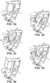
- Figures 3a to 3e show the steps involved in inflating an energy absorbing member 14 attached to a child restraint apparatus 1.
- the energy absorbing member 14 is lying in a deflated state against the outer side edge 16 of the child seat 1.
- the energy absorbing member 14 is attached along one substantially vertical edge to the outer side edge 16 of the child car seat 1 such that the energy absorbing member may be folded outwardly and forwardly toward the front of the child seat 1 as shown in Figure 3b in order to access the orifice or vent 19.
- the other substantially vertical edge of the energy absorbing member is provided with a strip 22a of hook and loop type material corresponding with a similar strip 22b provided on the outer side edge 16 of the child seat 1.
- These strips 22a, 22b seek to ensure that the energy absorbing member remains against the side edge 16 and prevent interference with the vent 19.
- the child seat 1 is provided with a locating member 24, which protrudes from the outer side edge 16 of the seat 1 to maintain the bottom edge of the energy absorbing member 14 in a predetermined location.
- the cap 20 is removed such that the vent 19 is open to allow air to enter the energy absorbing member 14 as shown in Figure 3c . Due to the resilient open cell foam structure of the energy absorbing member 14, the energy absorbing member 14 inflates to its inflated state as shown in Figure 3d . The energy absorbing member may then be folded back to lye against the outer side edge of the child seat 1 as shown in Figure 3e with the cap 20 removed such that the orifice 19 is left open.
- Figures 4a to 4h show the steps to deflate the energy absorbing member 14 attached to an outer side edge 16 of a child restraint apparatus 1.
- Figure 4a shown the energy absorbing member 14 in an inflated state lying against the outer side edge 16 of the child restraint apparatus in the form of a child seat 1. In this position, the orifice 19 is concealed by the energy absorbing member 14 and thereby protected from interference.
- the energy absorbing member 14 is folded forward to reveal the orifice or vent 19 and cap 20 as shown in Figure 4b .
- the cap 20 is placed on the vent 19 as shown in Figure 4c .
- the energy absorbing member 14 is then folded back against the out side edge 16 of the child seat 1 as shown in Figure 4d .
- the energy absorbing member 14 is deflated by compressing the energy absorbing member 14 against the outer side edge 16 of the child seat 1.
- compression which may be performed by hand, starts initially at the top of the energy absorbing member 14 and then proceeding towards the middle and bottom of the energy absorbing member 14 as shown in Figures 4e, 4f and 4g respectively.
- Figure 4h shows the energy absorbing member 14 in its uninflated state.
- an energy absorbing member 14a is provided between the child car seat 1 and the interior wall of the vehicle as shown in Figure 5 to reduce the impact between the interior wall and child car seat 1 in the event of a crash.
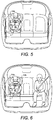
- the child car seat is provided with an energy absorbing member 14a, 14b on both sides of the child seat 1 as shown in Figure 6 to reduce the impact between the interior wall and child car seat 1 in the event of a crash and also an adjacent passenger.
- an energy absorbing member 14a, 14b on both sides of the child seat 1 as shown in Figure 6 to reduce the impact between the interior wall and child car seat 1 in the event of a crash and also an adjacent passenger.
- Such an arrangement would also be useful in the case that the child car seat is positioned in the centre or middle rear seat of a vehicle to protect adjacent passengers on either side of the vehicle.
- the energy absorbing member has been shown comprised of open cell foam layers, alternative embodiments include hollow airbags and combinations of open cell foam layers and EPS [Expanded Polystyrene].
- the size of the air vent and type and combination of layers is chosen to provide optimum deceleration characteristics.
- the energy absorbing member may be formed in different shapes and be located at various positions on the side of the child card seat to provide optimum protection against impact with an adjacent passenger.
- the thickness of the energy absorbing member may be limited by the ability of a passenger to sit adjacent to the child car seat and the projection. Typically the thickness of the energy absorbing member is 100 mm.
- An additional energy absorbing member may be provided at a lower level of the child seat in order to seek to reduce the impact with the pelvis of an adjacent passenger in the event of a crash.
- the energy absorbing member may be extended over the full side surface of the child seat.
- the energy absorbing member When the energy absorbing member is deflated, it may be stored by being rolled inside or underneath a cover of the child seat, folded, or placed in a separate pocket.
- a bellows may also be provided, comprising a hard surface for compressing the member.
- an energy absorbing member may be formed as a separate stand alone unit, into which the child seat may be located.
- the energy absorbing member may be applied to child booster seats, infant carriers,, cots, both forward and rearward facing systems, and other child restraint systems (CRS) and the like.
- CRS child restraint systems
Landscapes
- Engineering & Computer Science (AREA)
- Aviation & Aerospace Engineering (AREA)
- Transportation (AREA)
- Mechanical Engineering (AREA)
- Health & Medical Sciences (AREA)
- Child & Adolescent Psychology (AREA)
- General Health & Medical Sciences (AREA)
- Seats For Vehicles (AREA)
Description
- The present invention relates to a child restraint apparatus for example a child car seat for use in a vehicle. In particular, the present invention concerns such apparatus for reducing the risk of injury to passengers present in the vehicle who are seated adjacent said child car seat in the event of a vehicle accident or the like.
- In this connection, it is well known to provide child car seats to carry children and infants safely in vehicles. Most commonly, the child car seat is located on the rear seat of a vehicle and is attached or restrained to the vehicle seat using a connection which makes use of a standard vehicle seat belt or dedicated connection points such as lower anchors, top tethers or those of the Isofix type. That said, child car seats may also be located on a front passenger seat of a vehicle, in which case, the child car seat is usually attached using the front passenger seat belt.
- When located on the rear seat of a vehicle, the seat area taken up by a child car seat typically extends over the at least the width of one of the rear seat cushions. As such, additional passengers are able to occupy the remaining rear vehicle seats, including the seat immediately adjacent the seat cushion occupied by the child car seat.
- In terms of their structure, child car seats typically comprise a seat portion, a back portion and a head portion to support the child or infant occupant. The child car seat may also comprise raised side portions, which serve to restrict transverse movement of the child in the child car seat. The seat, back, head and raised side portions are commonly formed of a plastics material. The child car seat thereby effectively provides a rigid protective shell or body which at least partially surrounds the occupant of the child car seat. The seat, back, head and side portions of the child car seat may be covered in foam or other suitable cushioning materials on their inner facing surfaces to provide both a soft comfortable support for the child or infant against the underlying harder rigid plastic surfaces, and furthermore to provide cushioning against the internal surfaces of the shell should the child car seat be subjected to a sudden acceleration or deceleration.
- In the event of a collision with another vehicle or object, such child car seats serve to properly restrain an occupant of the seat and to improve their immediately subsequent kinematics, thereby reducing the severity of injury to the child or infant. Further impact protection is afforded by the rigid shell which partially surrounds the occupant of the child car seat.
- In a side impact to the vehicle, the fixings of the child seat with the vehicle, e.g. lower anchors, top tethers, Isofix connection points or the seat belt, may as a result of sufficient forces from the vehicle impact, permit the child car seat to move to some degree in a direction substantially in line with the direction of the vehicle impact. The amount and direction of movement of the child car seat will depend on a number of factors including the magnitude and direction of vehicle impact and the fixing method employed. A passenger occupying a seat adjacent to the child car seat, for example the middle rear seat of the vehicle, may as a result be impacted by the child car seat as the child car seat moves. Consequently, a passenger sitting adjacent the child seat may themselves suffer injury to the side of their body, including the torso, arms and/or upper leg areas, depending on the shape of the child car seat and where precisely the child car seat impacts the passenger.
- In addition to injury that may be caused to an adjacent passenger, the impact of the child car seat on the adjacent passenger may also cause a sudden deceleration to the child car seat. This sudden deceleration may in turn cause injury to the occupant of the car child seat, as a result of the potentially high forces exerted in particular on the child seat occupant=s head and neck.
- If the side impact of the vehicle should however occur on the opposite side of the vehicle, i.e. when the child car seat is positioned furthest from the point of impact on the rear seat of a vehicle, then there is a risk that the adjacent passenger to the child car seat will in this instance move towards the child car seat. Again there is a risk that the adjacent passenger will be injured as a result of impact with the child car seat, for example injury to the pelvis. Similarly, the occupant of the child car seat, due to the sudden impact, may be subjected to unduly high forces in particular to the occupant=s head and neck. Furthermore, the impact of the adjacent passenger with the child car seat may also in turn result in the child car seat impacting with the interior side of the vehicle and causing further injuries to the occupant of the child car seat.
- Document
US-B-7125073 discloses a child restraint apparatus having an energy absorbing member and a vent. The present invention seeks to overcome the aforementioned problems and seeks to reduce the likelihood of injury to a passenger sitting adjacent a child restraint such as a child car seat. - The above mentioned needs and others that will be readily apparent to those skilled in the art are met by the invention, which in one aspect provides a child restraint apparatus for restraining a child within a vehicle interior. The apparatus has a body comprising an internal area for receiving a child, and an energy absorbing member which, in use, extends over at least part of an external surface of the body and which faces away from the internal area. The energy absorbing member seeks to cushion an impact that may occur with a passenger adjacent the child restraint apparatus in the event of a crash and thereby reduce the likelihood of injury to the passenger.
- Optionally, the energy absorbing member comprises a deformable chamber. A deformable chamber allows the energy absorbing member to be deflated allowing the child restraint apparatus to be more readily stored. The chamber then need only be deployed when the child restraint apparatus is installed in a vehicle.
- Optionally, the deformable chamber has a vent, the vent being configured to allow controlled expulsion of air from the chamber on deformation thereof. The vent seeks to allow the dissipation of energy during impact with an adjacent passenger to be controlled.
- Optionally, the chamber is provided with open cell foam. Open cell foam is a readily available material which may be easily formed to the required configuration and which provides resilient, controlled air release characteristics.
- Optionally, the energy absorbing member comprises one or more resilient layers. In this way, layers may be provided each with different energy absorbing characteristics and thereby the properties of the energy absorbing member may be tailored to the particular application.
- Optionally, the energy absorbing member comprises an air tight membrane around its periphery. The air tight membrane seeks to ensure that in the event of an impact, air is only permitted to escape through the vent provided in the chamber in a controlled manner.
- Optionally, the energy absorbing member is attached to the child restraint apparatus using fastening means. Suitable fixings means may include plastic rivets, hook and loop type fastenings, adhesive or snap fittings.
- Optionally, the energy absorbing member is attached to the outer side edge of the child restraint apparatus along one edge of the said energy absorbing member. In this way, the energy absorbing member can be folded away from the outer side edge of the child restraint apparatus to assist with inflation or deflation of the energy absorbing member or to conceal an orifice or vent.
- According to a further aspect of the present invention there is provided a method of operating a child restraint apparatus within a vehicle, the apparatus having an externally positioned energy absorbing member in the form of a vented deformable chamber, the method comprising the steps of providing the child restraint apparatus in a vehicle interior with the chamber collapsed and the vent closed, then with the child restraint apparatus in position in vehicle, opening the vent such that air enters the chamber, the vent thereafter being left open so as to provide controlled venting in the event of a deformation of the chamber as a result of an accident. The energy absorbing member need only be deployed when the child restraint apparatus is installed in a vehicle, thereby allowing the child restraint apparatus to be more easily stored and handled.
- Several aspects of the invention have been set forth above. Other aspects will be readily apparent to one skilled in the art when the following detailed description of the invention is considered in conjunction with the accompanying drawings.
-
Figure 1 is a front view of a child restraint apparatus installed in a vehicle comprising an energy absorbing member in a preferred embodiment of the present invention; -
Figure 2 is a section through the child restraint apparatus and energy absorbing member as shown inFigure 1 ; -
Figures 3a to 3e show a side and rear view of a child restraint apparatus and the steps involved in inflating an energy absorbing member extending over a part of the external surface thereof; -
Figures 4a to 4h show a side and rear view of a child restraint apparatus and the steps involved in deflating an energy absorbing member extending over a part of the external surface thereof; -
Figure 5 is a front view of a child restraint apparatus installed in a vehicle comprising an energy absorbing member in a further preferred embodiment of the present invention; and -
Figure 6 is a front view of a child restraint apparatus installed in vehicle comprising an energy absorbing member in a further preferred embodiment of the present invention. -
Figure 1 shows a child restraint apparatus in the form of a child car seat shown generally as 1. Thechild car seat 1 comprises a seat portion 2, aback portion 3, a head portion 4 and side portions 5,6 to form a substantially rigid shell or body portion which partially surrounds theoccupant 7 of the child car seat. The body comprises an internal area for receiving a child and thecar seat 1 is further provided with an adjustable safety harness 8 and abuckle 9 which serves to restrain thechild 7 in theseat 1. - In the embodiment shown in
Figure 1 , thechild car seat 1 is located on the right side of arear seat bench 10 of a vehicle with respect to the direction of travel. In the embodiment shown, the occupant of the child car seat is facing forwardly, i.e. away from the rear vehicle seat back 11. The child car seat is attached by means of an Isofix type connection (not shown). When in position, thechild seat 1 takes up the area of one rear vehicle cushion, thereby leaving the seats or cushions adjacent to the installed child car seat free for other passengers to use. - A
passenger 12 seated in the middle or central rear vehicle seat is restrained by alap belt 13, although some vehicles may be provided with 3-point safety belts. - On an external surface of the body of the chid car seat, an
energy absorbing member 14 is provided, which extends over at least part of an external surface of the body. Theenergy absorbing member 14 faces away from the internal area of the seat, where a child may be restrained. -
Figure 2 shows a section through thechild car seat 1 and theenergy absorbing member 14. Theenergy absorbing member 14 comprises threelayers 15 of open cell foam aligned with theleft side edge 16 of the child car seat or shell portion. In theirinner edge 17 the foam layers 15 are formed to the outer surface of theleft side 16 of thechild car seat 1. The foam layers 15 are resilient and provide a certain degree of elastic deformability. The layers offoam 15 are covered with an airtight membrane 18, formed of canvas or other suitable material, around the outer periphery of thedevice 14 to produce a deformable chamber. In a lower surface of the membrane, a vent in the form of anorifice 19 is provided. In this embodiment, the location of theorifice 19 is chosen such that theorifice 19 is not blocked as a result of contact between theside 17 of theenergy absorbing member 14 and the side of theshell portion 16 or anadjacent passenger 12. Theorifice 19 may be provided with a sealingcap 20. The foam layers 15 may be compressed and the device deflated and sealed using thecap 20 in order to assist in installation and storage of the child restraint apparatus. - The
energy absorbing member 14 is attached to the child car seat using plastic rivets 21. Alternative forms of attachment include for example adhesive, hook and loop type fasteners or snap fittings. - When the
child car seat 1 is installed in a vehicle, the sealingcap 20 is removed and air is allowed to flow through theorifice 19 into the airtight membrane 18, and thereby allow theopen cell foam 15 to expand to its normal uncompressed state. Once installed, theorifice 19 is left open. - In the event of a crash, in particular from a side impact with another vehicle or object, even with the
child seat 1 being fixed to thevehicle seat 10, there will be a tendency for thechild car seat 1, or the passenger adjacent thechild seat 1, to move as a result of the high impact forces. In the case of a passenger sitting adjacent to the child seat to which no energy absorbing member is attached, the child car seat will impact with the adjacent passenger with a risk that the force of impact will cause injury to both the passenger and the occupant of the child car seat. - When the
child car seat 1 is provided with theenergy absorbing member 14 on itsouter side 16 between thechild car seat 1 and anadjacent passenger 12, the risk of injury to bothadjacent passenger 12 and theoccupant 7 of thechild car seat 1 can be reduced. In the event of a crash, the impact of anadjacent passenger 12 on theenergy absorbing member 14, causes theopen cell foam 15 to be compressed, causing air to be exhausted through the vent ororifice 19. Because theopen cell foam 15 compresses and deflates on impact with theadjacent passenger 12, it thereby decelerates thepassenger 12 and/orchild car seat 1 depending on the direction of impact and protects thepassenger 12 from the rigidplastic shell 16 of the child car seat. Further, as air is allowed to exhaust from theenergy absorbing member 14, there is less likelihood that theadjacent passenger 12 will rebound after impact with thechild car seat 1. - The size of the vent or
orifice 19 affects the rate at which air may be exhausted and thereby influences the ability of theenergy absorbing member 14 to reduce the impact forces of the child car seat on an adjacent passenger. If the energy absorbing member is allowed to deflate too rapidly, then bottoming out occurs and little or no protection is afforded. However, if the foam layers 15 are too resilient and/or air is not allowed to escape from theorifice 19 at a fast enough rate, there is a risk that thechild car seat 1 will rebound off anadjacent passenger 12. The energy absorbing member may be provided with a number of vents to allow air to escape in the event of an impact. -
Figures 3a to 3e show the steps involved in inflating anenergy absorbing member 14 attached to achild restraint apparatus 1. - In
Figure 3a , theenergy absorbing member 14 is lying in a deflated state against theouter side edge 16 of thechild seat 1. In the embodiment shown, theenergy absorbing member 14, is attached along one substantially vertical edge to theouter side edge 16 of thechild car seat 1 such that the energy absorbing member may be folded outwardly and forwardly toward the front of thechild seat 1 as shown inFigure 3b in order to access the orifice or vent 19. The other substantially vertical edge of the energy absorbing member is provided with astrip 22a of hook and loop type material corresponding with asimilar strip 22b provided on theouter side edge 16 of thechild seat 1. Thesestrips side edge 16 and prevent interference with thevent 19. Thechild seat 1 is provided with a locatingmember 24, which protrudes from theouter side edge 16 of theseat 1 to maintain the bottom edge of theenergy absorbing member 14 in a predetermined location. - Once the
energy absorbing member 14 has been folded forward and thevent 19 has been exposed, thecap 20, is removed such that thevent 19 is open to allow air to enter theenergy absorbing member 14 as shown inFigure 3c . Due to the resilient open cell foam structure of theenergy absorbing member 14, theenergy absorbing member 14 inflates to its inflated state as shown inFigure 3d . The energy absorbing member may then be folded back to lye against the outer side edge of thechild seat 1 as shown inFigure 3e with thecap 20 removed such that theorifice 19 is left open. -
Figures 4a to 4h show the steps to deflate theenergy absorbing member 14 attached to anouter side edge 16 of achild restraint apparatus 1. -
Figure 4a shown theenergy absorbing member 14 in an inflated state lying against theouter side edge 16 of the child restraint apparatus in the form of achild seat 1. In this position, theorifice 19 is concealed by theenergy absorbing member 14 and thereby protected from interference. When deflation is required, theenergy absorbing member 14 is folded forward to reveal the orifice or vent 19 andcap 20 as shown inFigure 4b . Thecap 20 is placed on thevent 19 as shown inFigure 4c . Theenergy absorbing member 14 is then folded back against theout side edge 16 of thechild seat 1 as shown inFigure 4d . - The
energy absorbing member 14 is deflated by compressing theenergy absorbing member 14 against theouter side edge 16 of thechild seat 1. To deflate theenergy absorbing member 14 fully, compression, which may be performed by hand, starts initially at the top of theenergy absorbing member 14 and then proceeding towards the middle and bottom of theenergy absorbing member 14 as shown inFigures 4e, 4f and 4g respectively. With thecap 20 in place, air may be expelled from the energy absorbing member but cannot enter; the cap thereby effects a one-way valve.Figure 4h shows theenergy absorbing member 14 in its uninflated state. - In a further embodiment, an
energy absorbing member 14a is provided between thechild car seat 1 and the interior wall of the vehicle as shown inFigure 5 to reduce the impact between the interior wall andchild car seat 1 in the event of a crash. - In a further embodiment the child car seat is provided with an
energy absorbing member child seat 1 as shown inFigure 6 to reduce the impact between the interior wall andchild car seat 1 in the event of a crash and also an adjacent passenger. Such an arrangement would also be useful in the case that the child car seat is positioned in the centre or middle rear seat of a vehicle to protect adjacent passengers on either side of the vehicle. - Although the energy absorbing member has been shown comprised of open cell foam layers, alternative embodiments include hollow airbags and combinations of open cell foam layers and EPS [Expanded Polystyrene]. The size of the air vent and type and combination of layers is chosen to provide optimum deceleration characteristics.
- The energy absorbing member may be formed in different shapes and be located at various positions on the side of the child card seat to provide optimum protection against impact with an adjacent passenger. The thickness of the energy absorbing member may be limited by the ability of a passenger to sit adjacent to the child car seat and the projection. Typically the thickness of the energy absorbing member is 100 mm.
- An additional energy absorbing member may be provided at a lower level of the child seat in order to seek to reduce the impact with the pelvis of an adjacent passenger in the event of a crash. Alternatively the energy absorbing member may be extended over the full side surface of the child seat.
- When the energy absorbing member is deflated, it may be stored by being rolled inside or underneath a cover of the child seat, folded, or placed in a separate pocket. To assist in the deflation of the energy absorbing member, a bellows may also be provided, comprising a hard surface for compressing the member.
- In an alternative embodiment, an energy absorbing member may be formed as a separate stand alone unit, into which the child seat may be located.
- Although, described with reference to child car seats, the energy absorbing member may be applied to child booster seats, infant carriers,, cots, both forward and rearward facing systems, and other child restraint systems (CRS) and the like.
Claims (11)
- Child restraint apparatus (1) for restraining a child (7) within a vehicle interior, the apparatus (1) having a body comprising an internal area for receiving a child (1), and an energy absorbing member (14) which, in use, extends over at least part of an external surface of the body and which faces away from the internal area,
wherein the energy absorbing member (14) comprises a deformable chamber being provided with one or more resilient foam layers (15),
wherein the deformable chamber further comprisesa vent (19) configured to allow air to flow therethrough into the deformable chamber thereby allowing the one or more resilient foam layers (15) to expand to an uncompressed state, andthe vent (19) further being configured to allow expulsion of air from the deformable chamber upon an impact on the energy absorbing member (14). - Child restraint apparatus (1) according to claim 1, wherein the vent (19) is configured to allow controlled expulsion of air from the chamber on deformation thereof.
- Child restraint apparatus (1) according to claim 1, wherein the chamber is provided with open cell foam.
- Child restraint apparatus (1) according to claim 1, wherein the energy absorbing member (14) comprises an air tight membrane (18) around its periphery.
- Child restraint apparatus (1) according to claim 1, wherein the energy absorbing member (14) is attached to the child restraint apparatus (1) using fixing means.
- Child restraint apparatus (1) according to claim 5, wherein the fixing means comprises plastic rivets (21).
- Child restraint apparatus (1) according to claim 5, wherein the fixing means comprises hook and look type fastenings.
- Child restraint apparatus (1) according to claim 1, wherein the energy absorbing member (14) is attached to the outer side edge (16) of the child restraint apparatus (1) along one edge of the said energy absorbing member (14).
- Child restraint apparatus (1) according to claim 1, wherein the energy absorbing member (14) extends over two external surfaces of the body, which surfaces face away from the internal area.
- Child restraint apparatus (1) according to claim 1, wherein a further energy absorbing member (14) is provided at a lower level of the child restraint apparatus (1).
- A method of operating a child restraint apparatus (1) within a vehicle, the apparatus (1) having an externally positioned energy absorbing member (14) in the form of a vented deformable chamber being provided with one or more resilient foam layers (15),
the method comprising the steps of:- providing the child restraint apparatus (1) in a vehicle interior with the chamber collapsed and the vent (19) closed,- then with the child restraint apparatus (1) in position in vehicle, opening the vent (19) such that air enters the chamber thereby allowing the one or more resilient foam layers (15) to expand to an uncompressed state, the vent (19) thereafter being left open so as to provide controlled venting in the event of a deformation of the chamber as a result of an accident.
Applications Claiming Priority (2)
| Application Number | Priority Date | Filing Date | Title |
|---|---|---|---|
| US11/954,979 US7717506B2 (en) | 2007-12-12 | 2007-12-12 | Child restraint apparatus for vehicle |
| PCT/US2008/086392 WO2009076514A2 (en) | 2007-12-12 | 2008-12-11 | Child restraint apparatus for vehicle |
Publications (3)
| Publication Number | Publication Date |
|---|---|
| EP2222500A2 EP2222500A2 (en) | 2010-09-01 |
| EP2222500A4 EP2222500A4 (en) | 2015-05-20 |
| EP2222500B1 true EP2222500B1 (en) | 2018-06-06 |
Family
ID=40752220
Family Applications (1)
| Application Number | Title | Priority Date | Filing Date |
|---|---|---|---|
| EP08859468.4A Active EP2222500B1 (en) | 2007-12-12 | 2008-12-11 | Child restraint apparatus for vehicle |
Country Status (8)
| Country | Link |
|---|---|
| US (1) | US7717506B2 (en) |
| EP (1) | EP2222500B1 (en) |
| KR (1) | KR101318548B1 (en) |
| CN (1) | CN101939190A (en) |
| AU (1) | AU2008335137B2 (en) |
| ES (1) | ES2686116T3 (en) |
| NZ (1) | NZ586480A (en) |
| WO (1) | WO2009076514A2 (en) |
Families Citing this family (56)
| Publication number | Priority date | Publication date | Assignee | Title |
|---|---|---|---|---|
| US9669739B1 (en) | 1999-11-08 | 2017-06-06 | Arjuna Indraeswaran Rajasingham | Vehicle occupant support |
| US10780857B1 (en) * | 2006-12-14 | 2020-09-22 | Arjuna Indraeswaran Rajasingham | Vehicle occupant support |
| US7654613B2 (en) * | 2008-01-14 | 2010-02-02 | Eric Bass | Head and body protection system for a child safety seat |
| US7748781B2 (en) * | 2008-01-14 | 2010-07-06 | Eric Bass | Head and body protection child safety seat |
| US8104829B2 (en) * | 2008-03-05 | 2012-01-31 | Cosco Management, Inc. | Juvenile motion-inhibitor system |
| US7726734B2 (en) * | 2008-07-22 | 2010-06-01 | Britax Child Safety, Inc. | Juvenile seating with resilient side impact protection |
| US7744154B2 (en) * | 2008-07-30 | 2010-06-29 | Cosco Management, Inc. | Energy-dissipation system |
| US8061768B2 (en) * | 2008-07-30 | 2011-11-22 | Cosco Management, Inc. | Energy-dissipation system |
| US8029054B2 (en) * | 2009-05-20 | 2011-10-04 | Cosco Management, Inc. | Energy-dissipation system |
| US8038209B2 (en) * | 2009-05-20 | 2011-10-18 | Cosco Management, Inc. | Energy-dissipation system |
| US8056972B2 (en) * | 2009-05-20 | 2011-11-15 | Cosco Management, Inc. | Energy-dissipation system |
| US8052210B2 (en) * | 2009-05-20 | 2011-11-08 | Cosco Management, Inc. | Energy-dissipation system |
| US8128165B2 (en) * | 2009-05-20 | 2012-03-06 | Cosco Management, Inc. | Energy-dissipation system |
| US20100295270A1 (en) * | 2009-05-20 | 2010-11-25 | Cosco Management, Inc. | Energy-dissipation system |
| US8056971B2 (en) * | 2009-05-20 | 2011-11-15 | Cosco Management, Inc. | Energy-dissipation system |
| US7959223B2 (en) * | 2009-05-20 | 2011-06-14 | Cosco Management, Inc. | Energy-dissipation system |
| ES2426225T5 (en) * | 2009-07-14 | 2024-03-05 | Britax Roemer Kindersicherheit Gmbh | Child seat with side impact protection |
| AU2011200689A1 (en) * | 2010-02-18 | 2011-09-01 | Britax Childcare Pty Ltd | Improvements relating to vehicle child restraints |
| HU3823U (en) * | 2010-03-11 | 2010-08-30 | Gubas Gabi | Safety airplane seat |
| US8905478B2 (en) * | 2010-03-17 | 2014-12-09 | Britax Child Safety, Inc. | Child safety seat with structural support |
| USD660605S1 (en) | 2010-03-17 | 2012-05-29 | Britax Child Safety, Inc. | Child safety seat |
| USD651418S1 (en) | 2010-03-17 | 2012-01-03 | Britax Child Safety, Inc. | Child safety seat |
| US8348337B2 (en) * | 2010-03-17 | 2013-01-08 | Britax Child Safety, Inc. | Child safety seat with energy absorbing apparatus |
| USD651417S1 (en) | 2010-03-17 | 2012-01-03 | Britax Child Safety, Inc. | Child safety seat |
| DE102011076702A1 (en) | 2011-05-30 | 2012-12-06 | TAKATA Aktiengesellschaft | Child seat for a motor vehicle |
| USRE47971E1 (en) * | 2012-06-01 | 2020-05-05 | Dorel Juvenile Group, Inc. | Energy-dissipation system |
| US8690237B2 (en) | 2012-06-07 | 2014-04-08 | Graco Children's Products Inc. | Child car seat and headrest with side impact energy absorption |
| DE202012102471U1 (en) * | 2012-06-18 | 2012-09-07 | Cybex Gmbh | Child seat for attachment to a motor vehicle seat |
| US9211820B2 (en) | 2012-11-01 | 2015-12-15 | Graco Children's Products Inc. | Child safety seat with side impact energy redirection |
| EP2746097B1 (en) * | 2012-12-21 | 2015-10-28 | Britax Childcare Pty Ltd. | Mechanical side impact protection for a child restraint |
| US10220734B2 (en) | 2013-03-05 | 2019-03-05 | Pidyon Controls Inc. | Car seat |
| US8911015B2 (en) | 2013-03-05 | 2014-12-16 | Yochanan Cohen | Car seat |
| US9487110B2 (en) | 2014-03-05 | 2016-11-08 | Pidyon Controls Inc. | Car seat |
| EP2826662B1 (en) | 2013-07-16 | 2018-09-19 | BRITAX RÖMER Kindersicherheit GmbH | Child safety seat |
| FR3010010B1 (en) * | 2013-08-30 | 2015-09-18 | Dorel France Sa | CAR SEAT FOR CHILDREN WITH OPTIMIZED REINFORCEMENT GROOVES |
| GB2522253B (en) * | 2014-01-20 | 2017-11-08 | Jankel Armouring Ltd | An improved seat |
| CN105329121B (en) | 2014-08-06 | 2018-06-12 | 宝钜儿童用品香港股份有限公司 | Side impact protection mechanism and child safety seat |
| US9616782B2 (en) | 2014-08-29 | 2017-04-11 | Pidyon Controls Inc. | Car seat vehicle connection system, apparatus, and method |
| MX2017013976A (en) | 2015-05-12 | 2018-03-14 | Pidyon Controls Inc | Car seat and connection system. |
| DE102016111608B4 (en) * | 2016-06-24 | 2018-10-25 | Curt Würstl Vermögensverwaltungs-Gmbh & Co. Kg | Child seat with side impact protection |
| US10011198B2 (en) | 2016-09-22 | 2018-07-03 | Joshua Hans Theander | Vehicular seating assembly, system and method |
| NO344017B1 (en) * | 2016-12-16 | 2019-08-19 | Torgersen Hans & Soenn | Child safety seat for a vehicle |
| AU2017279736B2 (en) | 2016-12-23 | 2023-12-14 | Britax Childcare Pty Ltd | Impact energy absorbing device |
| DE102017120516A1 (en) | 2017-09-06 | 2019-03-07 | Bbp Kunststoffwerk Marbach Baier Gmbh | Vehicle seat, seat component and impact protection |
| CN108790970B (en) * | 2018-05-04 | 2024-07-26 | 好孩子儿童用品有限公司 | Child safety seat capable of preventing side collision |
| CN110962709B (en) * | 2018-10-01 | 2022-10-11 | 明门瑞士股份有限公司 | Automobile safety seat and side impact protection mechanism thereof |
| AU2020201572B2 (en) * | 2019-03-13 | 2021-11-25 | Britax Child Safety, Inc. | Child safety seat |
| WO2021090316A1 (en) | 2019-11-04 | 2021-05-14 | Babyark Ltd | Methods and systems for generating training and executing a model for detecting safety seat events |
| CN114981124B (en) * | 2019-11-04 | 2025-02-25 | 婴儿方舟有限公司 | Side impact safety seat |
| WO2021090313A1 (en) | 2019-11-04 | 2021-05-14 | Mobius Protection Systems Ltd. | Car seat base with installation guidance and locking anti-rebounding mechanism |
| US20230016423A1 (en) | 2019-12-10 | 2023-01-19 | Inneva Limited | Side Impact Protection Device |
| EP3858662A1 (en) * | 2020-02-03 | 2021-08-04 | Osann GmbH | Child seat |
| AU2021201210B1 (en) * | 2021-02-24 | 2021-07-29 | BRITAX RÖMER Kindersicherheit GmbH | Child safety seat |
| US12472854B2 (en) | 2022-09-26 | 2025-11-18 | Dorel Juvenile Group, Inc. | Child restraint |
| US12515568B2 (en) | 2022-09-26 | 2026-01-06 | Dorel Juvenile Group, Inc. | Child restraint |
| US20250262995A1 (en) | 2024-02-20 | 2025-08-21 | Britax Child Safety, Inc. | Car seat with adjustable side impact protection and adjustable self-deploying inner arm rests |
Family Cites Families (21)
| Publication number | Priority date | Publication date | Assignee | Title |
|---|---|---|---|---|
| US1468072A (en) * | 1921-04-14 | 1923-09-18 | Ogle Hubert Millas | Comfort cushion |
| US3770315A (en) | 1972-12-18 | 1973-11-06 | Hardman Aerospace | Selectively adjustable lumbar support for aircraft seats and the like |
| US4611851A (en) | 1981-10-19 | 1986-09-16 | Tecseat Ltd. | Pneumatic bicycle saddle |
| US4555140A (en) | 1984-02-23 | 1985-11-26 | Japan | Vehicle seat |
| US5033133A (en) * | 1990-09-13 | 1991-07-23 | Nissen Sports Academy, Inc. | Seat cushion |
| US5100169A (en) * | 1990-11-27 | 1992-03-31 | Goor Associates, Inc. | Integral inflatable occupant restraint system |
| US5292176A (en) * | 1992-09-04 | 1994-03-08 | Babystar | Inflatable child vehicle seat |
| US5558398A (en) | 1993-11-08 | 1996-09-24 | Santos; James P. | Self-adjusting seating system |
| US5829829A (en) | 1996-10-25 | 1998-11-03 | Graco Children's Products Inc. | Removable/adjustable head support |
| JPH10157553A (en) * | 1996-12-02 | 1998-06-16 | Tokai Rika Co Ltd | Children's seat |
| JPH11196970A (en) * | 1998-01-13 | 1999-07-27 | Aprica Kassai Inc | Cushion structure of childcare implement |
| EP1285810B1 (en) * | 2001-08-21 | 2007-11-07 | Britax Excelsior Limited | Child safety seat |
| US7125073B2 (en) | 2003-02-25 | 2006-10-24 | Takata Corporation | Child seat |
| JP2004314798A (en) * | 2003-04-16 | 2004-11-11 | Takata Corp | Child seat |
| JP2004314799A (en) * | 2003-04-16 | 2004-11-11 | Takata Corp | Child seat |
| US7232182B2 (en) | 2003-02-25 | 2007-06-19 | Takata Corporation | Child seat |
| US7234771B2 (en) * | 2003-10-23 | 2007-06-26 | Britax Child Safety, Inc. | Child safety seat with adjustable head restraint |
| US7070238B1 (en) | 2005-07-26 | 2006-07-04 | Britax Child Safety, Inc. | Custom-moldable seating product and method for using same |
| DE202005014100U1 (en) * | 2005-09-08 | 2005-12-08 | Hauck Gmbh & Co. Kg | Safety seat, in particular, for babies and young children comprises a plastic shell with raised side walls and a lining incorporating protective cushion elements of soft foamed polyurethane |
| DE202006010876U1 (en) | 2006-07-10 | 2006-09-28 | Takata-Petri Ag | Energy absorber for motor vehicle seat or child seat, has covering of flexible material wrapped around foam core |
| ES1065298Y (en) | 2007-04-23 | 2007-10-16 | Jane Sa | SECURITY DEVICE BEFORE COLLISIONS, APPLICABLE TO CHILD SEATS |
-
2007
- 2007-12-12 US US11/954,979 patent/US7717506B2/en active Active
-
2008
- 2008-12-11 EP EP08859468.4A patent/EP2222500B1/en active Active
- 2008-12-11 CN CN200880126432XA patent/CN101939190A/en active Pending
- 2008-12-11 KR KR1020107015370A patent/KR101318548B1/en active Active
- 2008-12-11 WO PCT/US2008/086392 patent/WO2009076514A2/en not_active Ceased
- 2008-12-11 NZ NZ586480A patent/NZ586480A/en unknown
- 2008-12-11 AU AU2008335137A patent/AU2008335137B2/en active Active
- 2008-12-11 ES ES08859468.4T patent/ES2686116T3/en active Active
Non-Patent Citations (1)
| Title |
|---|
| None * |
Also Published As
| Publication number | Publication date |
|---|---|
| WO2009076514A3 (en) | 2010-05-06 |
| NZ586480A (en) | 2012-03-30 |
| EP2222500A2 (en) | 2010-09-01 |
| KR101318548B1 (en) | 2013-10-16 |
| US7717506B2 (en) | 2010-05-18 |
| US20090152913A1 (en) | 2009-06-18 |
| WO2009076514A2 (en) | 2009-06-18 |
| CN101939190A (en) | 2011-01-05 |
| KR20100115737A (en) | 2010-10-28 |
| AU2008335137B2 (en) | 2013-03-14 |
| ES2686116T3 (en) | 2018-10-16 |
| AU2008335137A1 (en) | 2009-06-18 |
| EP2222500A4 (en) | 2015-05-20 |
Similar Documents
| Publication | Publication Date | Title |
|---|---|---|
| US7717506B2 (en) | Child restraint apparatus for vehicle | |
| US7748781B2 (en) | Head and body protection child safety seat | |
| US7654613B2 (en) | Head and body protection system for a child safety seat | |
| JP2818642B2 (en) | Active knee pillow operated with built-in airbag | |
| EP1486384B1 (en) | Child seat with airbag | |
| US8702120B2 (en) | Active bolster deployed from vehicle seat | |
| EP1369314B1 (en) | Occupant protection apparatus | |
| US7758069B2 (en) | Knee airbag and restraint system for suppressing deployment of head/torso airbag | |
| KR101765353B1 (en) | Child seat with impact protection | |
| CN100431868C (en) | Children's seat | |
| US5782529A (en) | Inflatable seat back | |
| US20040169406A1 (en) | Child seat | |
| US11958428B2 (en) | Airbag device and vehicle seat | |
| JP2001239872A (en) | Occupant crash protection device | |
| US8485580B2 (en) | Apparatus for protecting a child's head | |
| EP1452406B1 (en) | Child seat | |
| JP2001524907A (en) | Side impact protection for passengers in vehicles | |
| JP2008062714A (en) | Crew protection device for vehicle | |
| CN121039001A (en) | Vehicles with restraints | |
| JP4148007B2 (en) | child seat | |
| JP2004314800A (en) | Child seat | |
| CN218805687U (en) | Vehicle seat and vehicle | |
| JP2004314799A (en) | Child seat | |
| KR20110100062A (en) | Passenger seat airbag device | |
| JP2004314798A (en) | Child seat |
Legal Events
| Date | Code | Title | Description |
|---|---|---|---|
| PUAI | Public reference made under article 153(3) epc to a published international application that has entered the european phase |
Free format text: ORIGINAL CODE: 0009012 |
|
| AK | Designated contracting states |
Kind code of ref document: A2 Designated state(s): AT BE BG CH CY CZ DE DK EE ES FI FR GB GR HR HU IE IS IT LI LT LU LV MC MT NL NO PL PT RO SE SI SK TR |
|
| AX | Request for extension of the european patent |
Extension state: AL BA MK RS |
|
| RIC1 | Information provided on ipc code assigned before grant |
Ipc: B60N 2/26 20060101AFI20101005BHEP |
|
| 17P | Request for examination filed |
Effective date: 20101108 |
|
| RBV | Designated contracting states (corrected) |
Designated state(s): AT BE BG CH CY CZ DE DK EE ES FI FR GB GR HR HU IE IS IT LI LT LU LV MC MT NL NO PL PT RO SE SI SK TR |
|
| DAX | Request for extension of the european patent (deleted) | ||
| A4 | Supplementary search report drawn up and despatched |
Effective date: 20150420 |
|
| RIC1 | Information provided on ipc code assigned before grant |
Ipc: B60N 2/28 20060101ALI20150414BHEP Ipc: B60N 2/26 20060101AFI20150414BHEP |
|
| GRAP | Despatch of communication of intention to grant a patent |
Free format text: ORIGINAL CODE: EPIDOSNIGR1 |
|
| RIC1 | Information provided on ipc code assigned before grant |
Ipc: B60N 2/28 20060101ALI20171206BHEP Ipc: B60N 2/42 20060101AFI20171206BHEP |
|
| INTG | Intention to grant announced |
Effective date: 20180111 |
|
| GRAS | Grant fee paid |
Free format text: ORIGINAL CODE: EPIDOSNIGR3 |
|
| GRAA | (expected) grant |
Free format text: ORIGINAL CODE: 0009210 |
|
| AK | Designated contracting states |
Kind code of ref document: B1 Designated state(s): AT BE BG CH CY CZ DE DK EE ES FI FR GB GR HR HU IE IS IT LI LT LU LV MC MT NL NO PL PT RO SE SI SK TR |
|
| REG | Reference to a national code |
Ref country code: GB Ref legal event code: FG4D |
|
| REG | Reference to a national code |
Ref country code: CH Ref legal event code: EP Ref country code: AT Ref legal event code: REF Ref document number: 1005707 Country of ref document: AT Kind code of ref document: T Effective date: 20180615 |
|
| REG | Reference to a national code |
Ref country code: IE Ref legal event code: FG4D |
|
| REG | Reference to a national code |
Ref country code: DE Ref legal event code: R096 Ref document number: 602008055561 Country of ref document: DE |
|
| REG | Reference to a national code |
Ref country code: SE Ref legal event code: TRGR |
|
| REG | Reference to a national code |
Ref country code: NL Ref legal event code: MP Effective date: 20180606 |
|
| REG | Reference to a national code |
Ref country code: ES Ref legal event code: FG2A Ref document number: 2686116 Country of ref document: ES Kind code of ref document: T3 Effective date: 20181016 |
|
| REG | Reference to a national code |
Ref country code: LT Ref legal event code: MG4D |
|
| REG | Reference to a national code |
Ref country code: NO Ref legal event code: T2 Effective date: 20180606 |
|
| PG25 | Lapsed in a contracting state [announced via postgrant information from national office to epo] |
Ref country code: BG Free format text: LAPSE BECAUSE OF FAILURE TO SUBMIT A TRANSLATION OF THE DESCRIPTION OR TO PAY THE FEE WITHIN THE PRESCRIBED TIME-LIMIT Effective date: 20180906 Ref country code: LT Free format text: LAPSE BECAUSE OF FAILURE TO SUBMIT A TRANSLATION OF THE DESCRIPTION OR TO PAY THE FEE WITHIN THE PRESCRIBED TIME-LIMIT Effective date: 20180606 Ref country code: FI Free format text: LAPSE BECAUSE OF FAILURE TO SUBMIT A TRANSLATION OF THE DESCRIPTION OR TO PAY THE FEE WITHIN THE PRESCRIBED TIME-LIMIT Effective date: 20180606 Ref country code: CY Free format text: LAPSE BECAUSE OF FAILURE TO SUBMIT A TRANSLATION OF THE DESCRIPTION OR TO PAY THE FEE WITHIN THE PRESCRIBED TIME-LIMIT Effective date: 20180606 |
|
| PG25 | Lapsed in a contracting state [announced via postgrant information from national office to epo] |
Ref country code: LV Free format text: LAPSE BECAUSE OF FAILURE TO SUBMIT A TRANSLATION OF THE DESCRIPTION OR TO PAY THE FEE WITHIN THE PRESCRIBED TIME-LIMIT Effective date: 20180606 Ref country code: HR Free format text: LAPSE BECAUSE OF FAILURE TO SUBMIT A TRANSLATION OF THE DESCRIPTION OR TO PAY THE FEE WITHIN THE PRESCRIBED TIME-LIMIT Effective date: 20180606 Ref country code: GR Free format text: LAPSE BECAUSE OF FAILURE TO SUBMIT A TRANSLATION OF THE DESCRIPTION OR TO PAY THE FEE WITHIN THE PRESCRIBED TIME-LIMIT Effective date: 20180907 |
|
| REG | Reference to a national code |
Ref country code: AT Ref legal event code: MK05 Ref document number: 1005707 Country of ref document: AT Kind code of ref document: T Effective date: 20180606 |
|
| PG25 | Lapsed in a contracting state [announced via postgrant information from national office to epo] |
Ref country code: NL Free format text: LAPSE BECAUSE OF FAILURE TO SUBMIT A TRANSLATION OF THE DESCRIPTION OR TO PAY THE FEE WITHIN THE PRESCRIBED TIME-LIMIT Effective date: 20180606 |
|
| PG25 | Lapsed in a contracting state [announced via postgrant information from national office to epo] |
Ref country code: EE Free format text: LAPSE BECAUSE OF FAILURE TO SUBMIT A TRANSLATION OF THE DESCRIPTION OR TO PAY THE FEE WITHIN THE PRESCRIBED TIME-LIMIT Effective date: 20180606 Ref country code: PL Free format text: LAPSE BECAUSE OF FAILURE TO SUBMIT A TRANSLATION OF THE DESCRIPTION OR TO PAY THE FEE WITHIN THE PRESCRIBED TIME-LIMIT Effective date: 20180606 Ref country code: IS Free format text: LAPSE BECAUSE OF FAILURE TO SUBMIT A TRANSLATION OF THE DESCRIPTION OR TO PAY THE FEE WITHIN THE PRESCRIBED TIME-LIMIT Effective date: 20181006 Ref country code: AT Free format text: LAPSE BECAUSE OF FAILURE TO SUBMIT A TRANSLATION OF THE DESCRIPTION OR TO PAY THE FEE WITHIN THE PRESCRIBED TIME-LIMIT Effective date: 20180606 Ref country code: CZ Free format text: LAPSE BECAUSE OF FAILURE TO SUBMIT A TRANSLATION OF THE DESCRIPTION OR TO PAY THE FEE WITHIN THE PRESCRIBED TIME-LIMIT Effective date: 20180606 Ref country code: RO Free format text: LAPSE BECAUSE OF FAILURE TO SUBMIT A TRANSLATION OF THE DESCRIPTION OR TO PAY THE FEE WITHIN THE PRESCRIBED TIME-LIMIT Effective date: 20180606 Ref country code: SK Free format text: LAPSE BECAUSE OF FAILURE TO SUBMIT A TRANSLATION OF THE DESCRIPTION OR TO PAY THE FEE WITHIN THE PRESCRIBED TIME-LIMIT Effective date: 20180606 |
|
| PG25 | Lapsed in a contracting state [announced via postgrant information from national office to epo] |
Ref country code: IT Free format text: LAPSE BECAUSE OF FAILURE TO SUBMIT A TRANSLATION OF THE DESCRIPTION OR TO PAY THE FEE WITHIN THE PRESCRIBED TIME-LIMIT Effective date: 20180606 |
|
| REG | Reference to a national code |
Ref country code: DE Ref legal event code: R097 Ref document number: 602008055561 Country of ref document: DE |
|
| PLBE | No opposition filed within time limit |
Free format text: ORIGINAL CODE: 0009261 |
|
| STAA | Information on the status of an ep patent application or granted ep patent |
Free format text: STATUS: NO OPPOSITION FILED WITHIN TIME LIMIT |
|
| 26N | No opposition filed |
Effective date: 20190307 |
|
| PG25 | Lapsed in a contracting state [announced via postgrant information from national office to epo] |
Ref country code: DK Free format text: LAPSE BECAUSE OF FAILURE TO SUBMIT A TRANSLATION OF THE DESCRIPTION OR TO PAY THE FEE WITHIN THE PRESCRIBED TIME-LIMIT Effective date: 20180606 Ref country code: SI Free format text: LAPSE BECAUSE OF FAILURE TO SUBMIT A TRANSLATION OF THE DESCRIPTION OR TO PAY THE FEE WITHIN THE PRESCRIBED TIME-LIMIT Effective date: 20180606 |
|
| REG | Reference to a national code |
Ref country code: CH Ref legal event code: PL |
|
| PG25 | Lapsed in a contracting state [announced via postgrant information from national office to epo] |
Ref country code: LU Free format text: LAPSE BECAUSE OF NON-PAYMENT OF DUE FEES Effective date: 20181211 Ref country code: MC Free format text: LAPSE BECAUSE OF FAILURE TO SUBMIT A TRANSLATION OF THE DESCRIPTION OR TO PAY THE FEE WITHIN THE PRESCRIBED TIME-LIMIT Effective date: 20180606 |
|
| REG | Reference to a national code |
Ref country code: IE Ref legal event code: MM4A |
|
| REG | Reference to a national code |
Ref country code: BE Ref legal event code: MM Effective date: 20181231 |
|
| PG25 | Lapsed in a contracting state [announced via postgrant information from national office to epo] |
Ref country code: IE Free format text: LAPSE BECAUSE OF NON-PAYMENT OF DUE FEES Effective date: 20181211 |
|
| PG25 | Lapsed in a contracting state [announced via postgrant information from national office to epo] |
Ref country code: BE Free format text: LAPSE BECAUSE OF NON-PAYMENT OF DUE FEES Effective date: 20181231 |
|
| PG25 | Lapsed in a contracting state [announced via postgrant information from national office to epo] |
Ref country code: LI Free format text: LAPSE BECAUSE OF NON-PAYMENT OF DUE FEES Effective date: 20181231 Ref country code: CH Free format text: LAPSE BECAUSE OF NON-PAYMENT OF DUE FEES Effective date: 20181231 |
|
| PG25 | Lapsed in a contracting state [announced via postgrant information from national office to epo] |
Ref country code: MT Free format text: LAPSE BECAUSE OF NON-PAYMENT OF DUE FEES Effective date: 20181211 |
|
| PG25 | Lapsed in a contracting state [announced via postgrant information from national office to epo] |
Ref country code: PT Free format text: LAPSE BECAUSE OF FAILURE TO SUBMIT A TRANSLATION OF THE DESCRIPTION OR TO PAY THE FEE WITHIN THE PRESCRIBED TIME-LIMIT Effective date: 20180606 |
|
| PG25 | Lapsed in a contracting state [announced via postgrant information from national office to epo] |
Ref country code: HU Free format text: LAPSE BECAUSE OF FAILURE TO SUBMIT A TRANSLATION OF THE DESCRIPTION OR TO PAY THE FEE WITHIN THE PRESCRIBED TIME-LIMIT; INVALID AB INITIO Effective date: 20081211 |
|
| PGFP | Annual fee paid to national office [announced via postgrant information from national office to epo] |
Ref country code: NO Payment date: 20241216 Year of fee payment: 17 |
|
| PGFP | Annual fee paid to national office [announced via postgrant information from national office to epo] |
Ref country code: TR Payment date: 20241203 Year of fee payment: 17 |
|
| PGFP | Annual fee paid to national office [announced via postgrant information from national office to epo] |
Ref country code: GB Payment date: 20251218 Year of fee payment: 18 |
|
| PGFP | Annual fee paid to national office [announced via postgrant information from national office to epo] |
Ref country code: FR Payment date: 20251217 Year of fee payment: 18 |
|
| PGFP | Annual fee paid to national office [announced via postgrant information from national office to epo] |
Ref country code: SE Payment date: 20251217 Year of fee payment: 18 |
|
| PGFP | Annual fee paid to national office [announced via postgrant information from national office to epo] |
Ref country code: ES Payment date: 20260119 Year of fee payment: 18 |
|
| PGFP | Annual fee paid to national office [announced via postgrant information from national office to epo] |
Ref country code: DE Payment date: 20251222 Year of fee payment: 18 |